

Page 1

Beacon Monitor
Operator’s Manual
for model:
FBM200A
Version 2.00
Page 2

ii
Information contained in this manual is subject to change without
notice. Please consult the website at www.wst.ca for new
Operator’s Manual updates. Complying with all applicable
copyright laws is the responsibility of the user. Without limiting the
rights under copyright, no part of this document may be
reproduced, stored in a retrieval system, or transmitted in any form
or by any means including but not limited to, electronic,
mechanical, photocopying, recording, or otherwise, or for any
purpose, without the written permission of WS Technologies Inc.
(WST). WST may have patents, patent applications, trademarks,
copyrights, or other intellectual property rights covering subject
matter in this document. Except as expressly provided in any
written license agreement from WST, the furnishing of this
document does not give you any license to these patents,
trademarks, copyrights, or other intellectual property.
The purchaser shall not in any event be entitled to, and WST shall
not be liable for indirect, special, incidental or consequential
damages of any nature including, without limitation, business
interruption costs, loss of profit or revenue, loss of data,
promotional or manufacturing expenses, overhead, injury to
reputation or loss of customers, even if WST has been advised of
the possibility of such damages. In any event, purchaser's
recovery from WST for any claim shall not exceed purchaser's
purchase price for the product giving rise to such claim irrespective
of the nature of the claim, whether in contract, tort, warranty, or
otherwise. WST shall not be liable for and purchaser shall
indemnify, defend and hold WST its agents, distributors, dealers,
successors and assigns harmless from any and all claims,
damages or losses, including injury or death, arising from or
relating to the use or failure of the products.
Copyright © WS Technologies Inc.
All rights reserved.
Printed in Canada
March 2013
Page 3

iii
CONTENTS
INTRODUCTION .............................................................................1
UNPACKING ...................................................................................1
BEACON MONITOR........................................................................2
Antenna Connection:....................................................................3
Optional Outdoor Antenna Installation: ........................................3
Installing the Application: .............................................................3
SETTING UP THE APPLICATION ..................................................5
Monitor Mode: ..............................................................................6
Monitor button........................................................................... 6
Map Button ............................................................................... 6
Setup button ............................................................................. 6
Status section ........................................................................... 6
Beacon Burst log area .............................................................. 7
Beacon Decode area ................................................................ 7
Full Screen button .................................................................... 7
Deleting records ....................................................................... 7
QR Code ................................................................................... 7
Map Mode: ...................................................................................8
Map Selections ......................................................................... 8
Selected Log Items Only .......................................................8
Location Beacons .................................................................8
Non-Location Beacons .........................................................9
Normal Mode, Self Test, Test Protocol .................................9
High Resolution Overlay .......................................................9
QR Code ...............................................................................9
Map Area .................................................................................. 9
Icons .....................................................................................9
Zoom .................................................................................. 10
Pan ..................................................................................... 10
Rotate or Tilt ...................................................................... 10
Bird’s Eye View....................................................................... 10
Monitor Bar ............................................................................. 10
Compass ................................................................................ 10
Setup Mode: .............................................................................. 11
Setup Menu ............................................................................ 11
Setup Panel ............................................................................ 11
Admin - Connections .............................................................. 12
Admin – Passwords ................................................................ 13
Passwords – Setup ............................................................ 13
Passwords – Login ............................................................ 13
Logout ................................................................................ 13
Password Reset ................................................................. 14
Page 4

iv
Alarms .................................................................................... 14
Receiver Setup – Receiver Alarms ........................................ 15
Audio/LED/Relay Alarm ..................................................... 15
Audio Disable ..................................................................... 15
Receiver Setup – Receiver Sensitivity ................................... 16
Computer Setup – Computer Alarms ..................................... 17
Visual Alarm ....................................................................... 18
Audio Alarm ....................................................................... 18
Resetting Alarms ............................................................... 18
Email Alerts ............................................................................ 19
Email – Conditions ............................................................. 19
Email - Configuration ......................................................... 19
SMS Alerts .............................................................................. 20
SMS – Conditions .............................................................. 20
SMS - Configuration .......................................................... 20
Customized Notifications ........................................................ 21
Help – About Beacon Monitor ................................................ 22
Help Contents - Updates ........................................................ 23
Help Contents - Frequently Asked Questions ........................ 23
Help Contents – Feedback ..................................................... 24
RECEIVING BURSTS .................................................................. 25
Data Files and Log Files: .......................................................... 26
XML Files ................................................................................ 26
Log File ................................................................................... 26
FREQUENTLY ASKED QUESTIONS .......................................... 27
SPECIFICATIONS ........................................................................ 29
Minimum Requirements ............................................................ 29
REGULATORY INFORMATION ................................................... 30
DECLARATION OF CONFORMITY ............................................. 31
WARRANTY INFORMATION ....................................................... 32
CALIBRATION .............................................................................. 32
RETURNS .................................................................................... 32
MISSION CONTROL CENTER CONTACT INFORMATION ....... 33
NOTES ......................................................................................... 34
Page 5

1
INTRODUCTION
Thank you for choosing the FBM200 Beacon Monitor. This
Operator’s Manual describes the installation and operation of the
Beacon Monitor.
UNPACKING
Lift up on the inner fold on the right side of the Beacon Monitor box
and remove the Beacon Monitor from the underside. The
accessories are in the box on the right. Be sure to keep the
accessories box for handy storage of the Beacon Monitor
Operator’s Manual and accessories when not in use.
Please verify the contents of your package. It should contain:
Beacon Monitor
Operator’s Manual
Antenna
USB Cable 10’ (3m)
Optional items include:
Outdoor Antenna
Antenna Extension cable
25’ (7.6m)
50’ (15m)
75’ (23m)
100’ (30m)
Antenna mounting hardware
Certificate of Calibration (optional)
NOTICE!
Install the Beacon Monitor software before
connecting the device to the USB port.
Page 6
2
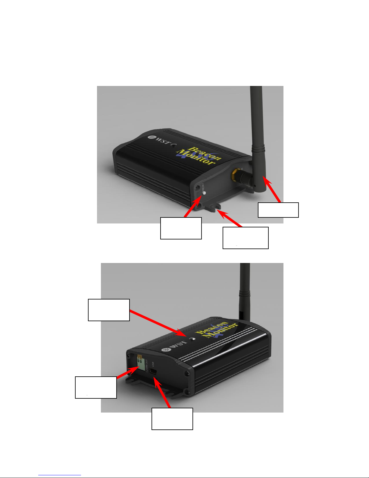
BEACON MONITOR
Please read this Operator’s Manual to become familiar with the
operation of the Beacon Monitor.
Relay
contacts
Reset
button
LED
Indicator
Antenna
USB
Interface
Mounting
Flange (4)
Page 7
3
Antenna Connection:
Connect the 406 MHz antenna to the front panel RF IN connector.
Optional Outdoor Antenna Installation:
Alternatively, if you have purchased the optional outdoor antenna,
install the outdoor antenna following the mounting instructions
included with the antenna. The U-bolts will fit a mast from
approximately 1.25” to 2.50” in diameter. Connect the Antenna
Extension cable between the antenna and the RF IN connector on
the Beacon Monitor.
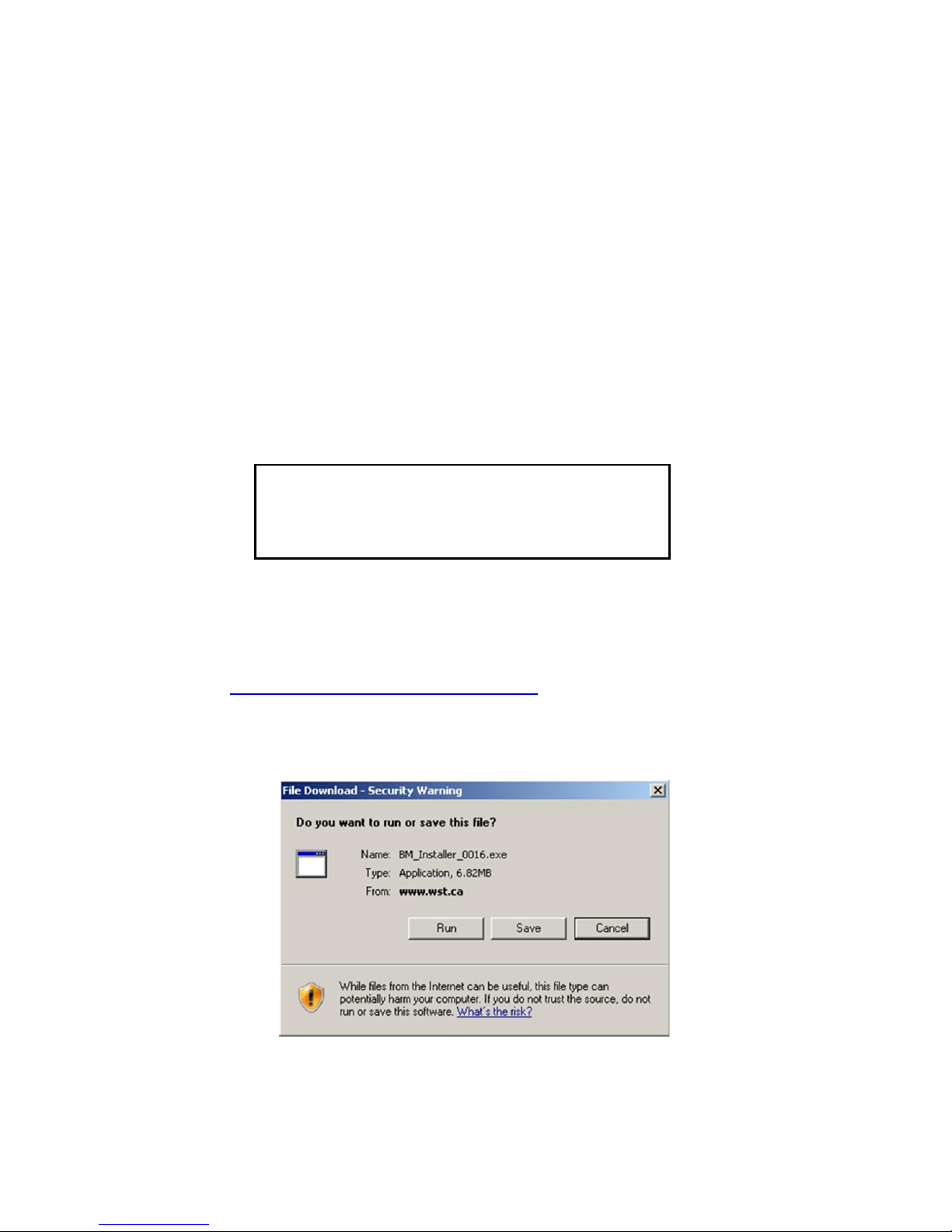
Installing the Application:
The Beacon Monitor application must be installed on your computer
prior to connecting the device.
Go to www.wst.ca/beacon_monitor.html and install the latest
version of the Beacon Monitor software. The following message will
appear.
Click Run to install the application on the computer.
NOTICE!
Install the Beacon Monitor software before
connecting the device to the USB port.
Page 8

4
The Beacon Monitor Setup screen will appear.
Click Next.
If JavaTM is not installed on your computer, you will be prompted to
install it. Follow all on-screen instructions.
Once completed click Finish.
The Beacon Monitor icon will appear
on your computer desktop.
Page 9
5
SETTING UP THE APPLICATION
Click on the Beacon Monitor icon. The Beacon Monitor application
will start and the following screen will be displayed:
Connect the FBM200 receiver to a USB port on the computer using
the supplied USB cable. This connection is both the power supply
and the communication link to the receiver. When the FBM200
receiver is located, the Connection Status in the Status section will
show Connected.
The LED Indicator on the top of the unit will glow red when first
plugged in, then will flash green when operating normally.
There are three main viewing modes:
1. Monitor Mode
2. Map Mode
3. Setup Mode
The following sections will discuss the setup and operation of the
software and hardware.
Page 10
6
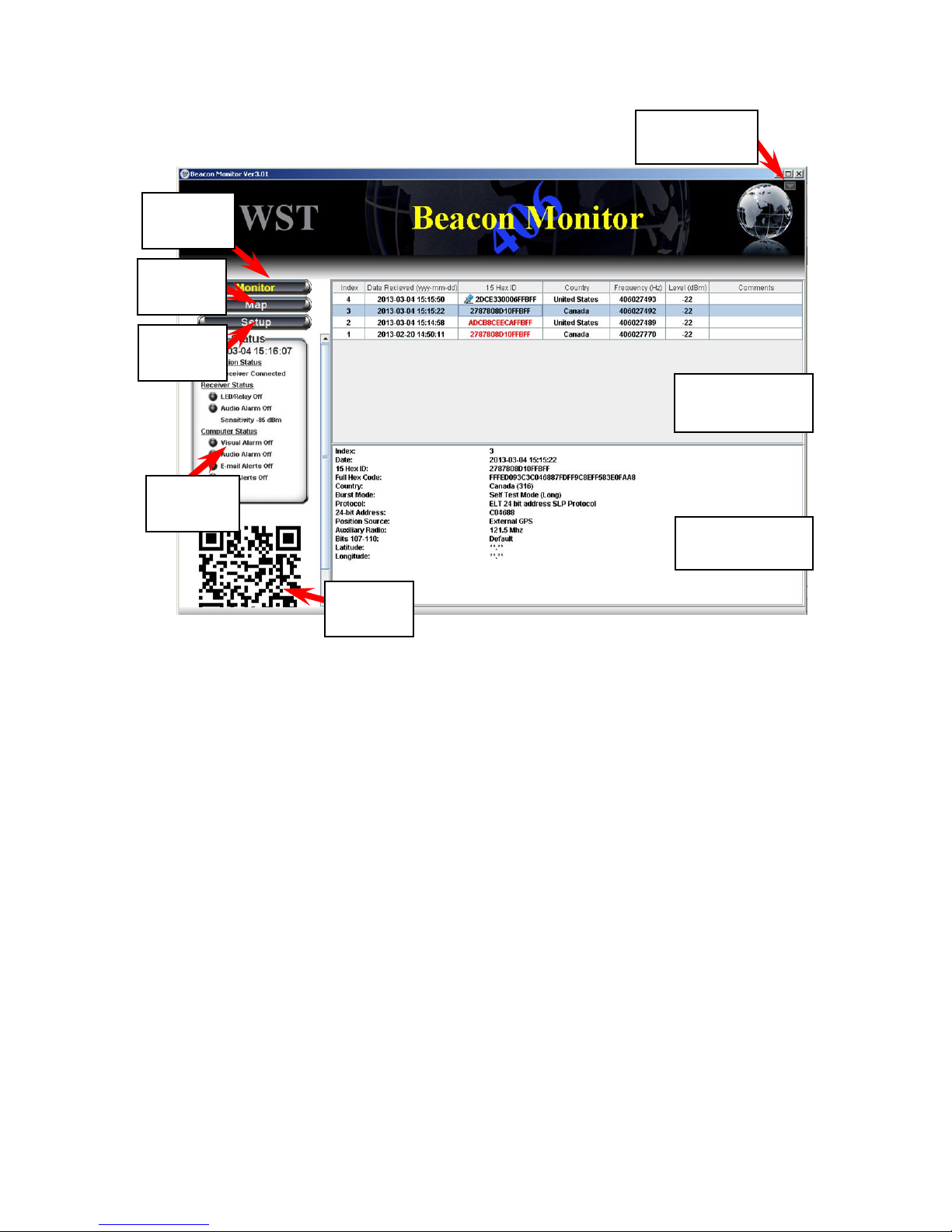
Monitor Mode:
The Monitor button will switch the screen to the Monitor mode. This
is the normal mode for monitoring beacon burst activity.
The Map button will switch the screen to the Map mode. This mode
allows the user to view actual locations of beacons and the receiver.
The Setup button will switch the screen to the Setup mode. This
mode allows the user to setup the application and receiver as
needed.
The Status section displays the status of the Receiver Connection,
the Receiver Status, and the Computer Status.
Monitor button
Map Button
Setup button
Status section
Monitor
button
Setup
button
Status
section
Beacon burst
log area
Beacon burst
decode area
Full Screen
button
Map
button
QR
code
Page 11

7
The Beacon Burst log area will automatically record and log all
received 406 MHz beacon bursts. The information in this section
includes date and time of beacon burst, beacon 15 Hex ID, country
code, beacon transmit frequency, receive level of beacon signal,
and a comments field.
All of the information can be sorted by clicking on the header of the
column that you wish to sort. When a new beacon burst is received,
all of the information will be automatically un-sorted.
Click in the comments field to add or modify a comment.
The Beacon Decode area shows the decoded message details for
any selected burst.
To maximize the Beacon Monitor screen click the Full Screen
button. To un-maximize the screen press it again.
To delete records, select a record and right click the mouse, then
click Delete record.
To delete multiple records, select individual records while holding
down the control button on your keyboard, right click and delete.
To delete a range of records select the first record, hold down the
shift key and select the last record. Right click and delete.
The selected beacon burst will have a QR Code
displayed below the Map Selections area. This QR Code contains
information about the burst including location data if present. It can
easily be read by a smart phone to make these details portable and
for use in other mapping applications.
Beacon Burst log area
Beacon Decode area
Full Screen button
Deleting records
QR Code
Page 12
8
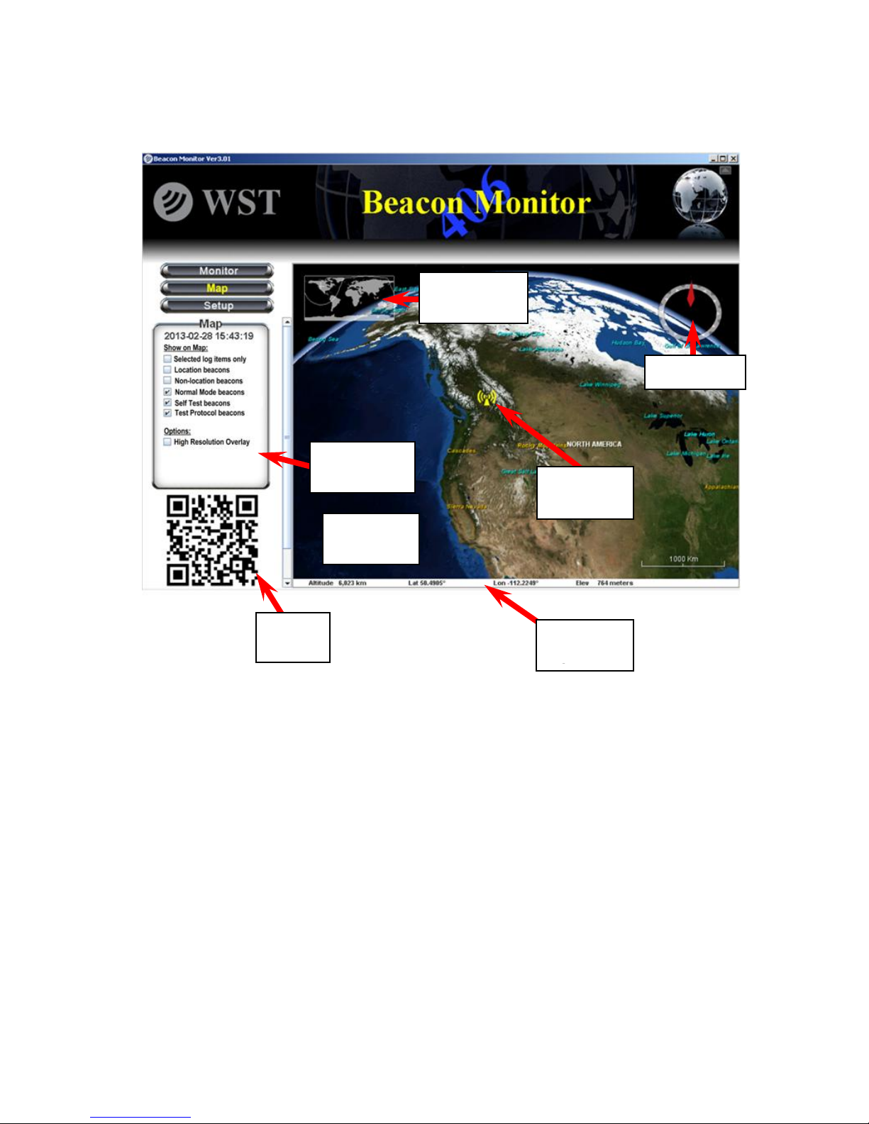
Map Mode:
Clicking on the Map button will take you to the Map mode.
This section lets the user control what beacons are shown on the
map.
Selected Log Items Only
Check the box when you want only the items selected in the Log
Area (Monitor Mode) to be viewed on the map.
Location Beacons
The user can check this box to show all location protocol beacons
on the map.
Map Selections
Map
selections
Monitor
bar
Bird’s Eye
window
Receiver
icon
Compass
Map
area
QR
Code
Page 13

9
Non-Location Beacons
The user can check this box to show all non-location protocol
beacons on the map. All non-location beacon icons will be placed in
a vertical column below the Receiver icon.
Normal Mode, Self Test, Test Protocol
The user can further filter which beacons will be displayed on the
map. Check or uncheck as needed.
High Resolution Overlay
The user can check this box if a high resolution image of the area is
desired.
QR Code
The selected beacon burst will have a QR Code displayed below
the Map Selections area. This QR Code contains information about
the burst including location data if present. It can easily be read by a
smart phone to make these details portable and for use in other
mapping applications.
The Map Area will show the Receiver icon and all of the received
beacon bursts as selected by the user.
Icons
If the decoded beacon includes location data, the beacon icon will
be at that location. If the decoded beacon burst does not show
location data or if the beacon is a non-location protocol, the beacon
icon will be shown below the Receiver icon.
Each beacon burst is represented on the map. ELTs are
represented by an Airplane, EPIRBs are represented by a ship,
PLBs are represented by a person.
A red icon represents a Normal Mode (Live Burst) and a green icon
represents Self-Test burst. A Test Protocol burst is represented by
a green question mark icon.
Mouse over any beacon icon will show the Index number so the
user can reference the same beacon on the Monitor page. Note that
the index number will change when items are deleted from the Log
Area on the Monitor page.
Map Area
Page 14

10
Clicking on a beacon icon will display the beacon’s decode details.
This balloon can be resized as appropriate by grabbing a corner
and dragging.
The map display can be controlled by the user.
Zoom
Use the mouse wheel to zoom in or out as desired.
Double click on the Receiver icon to zoom in automatically.
Pan
Left click and drag left, right, up, or down; or use the keyboard
arrow keys.
Rotate or Tilt
Right click and drag left or right to rotate.
Right click and drag up or down to tilt.
This shows a bird’s eye view of the current map display.
The monitor bar shows the altitude, the mouse position latitude,
longitude (in decimal degrees), and elevation.
The compass points to true North.
Bird’s Eye View
Monitor Bar
Compass
Page 15

11
Setup Mode:
Clicking on the Setup button will take you to the Setup mode.
The setup menu has a selection of items. See details of each
section in the Setup Items section below.
The Setup panel is the information or setup area for each item in
the Setup menu.
Setup Menu
Setup Panel
Setup
menu
Setup
button
Setup
panel
Page 16

12
Select a name for the connected receiver (maximum 8 characters).
The latitude and longitude of the receiver must be entered for the
receiver to show on the map. Use decimal degrees format.
Click Apply to save any changes.
Admin - Connections
Page 17

13
Passwords – Setup
If you wish to prevent an unauthorized person from making changes
to the Beacon Monitor setup, then the password protection must be
enabled. Click the Enable password protection box and enter the
desired password (4 to 12 characters).Then re-type the password
and click Apply.
Passwords – Login
Enter your password and click OK to login.
Logout
If the Beacon Monitor program is password protected, a
Login/Logout button will appear in the top right area of the screen.
For security, be sure to click Logout once you are finished
changing items in the Setup mode, otherwise you will automatically
be logged out after 10 minutes.
Admin – Passwords
Page 18

14
Password Reset
If you forget your password, the password protection can be reset.
Disconnect the unit from the Computer. Press and hold the reset
button on the FBM200 while connecting the USB cable to the unit. If
you wish to reinstate password protection then enter a new
password.
All 406 MHz beacon bursts are encoded as either:
1. Normal Mode (Live Burst)
2. Self Test mode
3. Test Protocol
The user has the option to set each alarm notification method based
on the mode of the received beacon burst. It is advised to always be
alerted when a Normal Mode (Live Burst) is detected so that the
user can take action and notify the authorities of a potential false
alert.
Check or un-check the boxes on the Receiver Alarms and
Computer Alarms setup pages to suit your requirements.
Click Apply to save the changes.
Note that all beacon bursts, regardless of burst mode, will be
recorded and logged. The user can delete unwanted records.
Alarms
NOTICE!
All Normal Mode bursts have the potential of being received by the
satellites causing a false alert. If you are confident that a Normal Mode
burst is definitely a false alert and has sufficient power to be received
by the satellites, then contact your local Mission Control Center (MCC).
Refer to the MCC list on page 32 of this Manual.
Page 19

15
Audio/LED/Relay Alarm
The receiver audio alert will sound, the LED Indicator will flash red,
and the relay contacts will close when a burst is received. The user
has the option to set each receiver alarm notification method based
on the mode of the received beacon burst. Check or un-check the
boxes on the Receiver Alarms setup page to suit your requirements.
These alarms are reset by clicking the Alarm Reset button on the
application or pressing the Reset button on the receiver.
Audio Disable
To deactivate the receiver audio alarm, check the Disable Audio
box.
Click Apply to save any changes.
Receiver Setup – Receiver Alarms
Page 20

16
The receiver sensitivity can be adjusted for each application. To
receive beacon bursts from far away, set the sensitivity to the
highest level of -125 dBm. This setting will receive bursts from near
also.
To receive only the beacons that are near, set the sensitivity to the
lowest level of -55 dBm.
The default sensitivity level is -115 dBm.
The Beacon Monitor has sophisticated algorithms for preventing
false triggering. However, burst reception may be hindered when
operating the Beacon Monitor in an electrically noisy environment.
You may need to remove the source of interference or reduce the
sensitivity of the Beacon Monitor.
Click Apply to save any changes.
Receiver Setup – Receiver Sensitivity
Apply
button
Slider
bars
Page 21

17
All 406 MHz beacon bursts are encoded as either:
1. Normal Mode (Live Burst)
2. Self Test Mode
3. Test Protocol
The user has the option to set each alarm notification method based
on the mode of the received beacon burst. It is advised to always be
alerted when a Normal Mode (Live Burst) is detected so that the
user can take action or notify the authorities of a potential false
alert.
There are two alarm notification methods on the computer; Visual
Alarm and Audio Alarm. When an alarm notification is triggered by a
received burst, an Alarm Reset button appears below the Map
button.
Computer Setup – Computer Alarms
Page 22

18
Check or un-check the boxes on the Computer Alarms setup page
to suit your requirements. Click Apply to save the changes.
Visual Alarm
For the Visual Alarm a red “ALERT” will flash at the top of the
screen.
Audio Alarm
For the Audio Alarm an audio alarm will sound through the
computer audio system.
Resetting Alarms
To clear the alarms, click on the Alarm Reset button.
Alarm Reset
button
NOTICE!
All Normal Mode bursts have the potential of being received by the
satellites causing a false alert. If you are confident that a Normal Mode
burst is definitely a false alert and has sufficient power to be received
by the satellites, then contact your local Mission Control Center (MCC).
Refer to the MCC list on page 32 of this Manual.
Page 23

19
Email alerts can be automatically sent to many email addresses.
Email – Conditions
Check or un-check the boxes to suit your requirements so that the
email notifications are sent for the corresponding beacon mode.
Email - Configuration
Enter the SMTP Mail server information for your outgoing mail
server. Contact your network administrator for this information.
Enter your email address. This will be the senders email.
If your outgoing mail server requires authentication select SMTP.
Enter the account username and account password.
Enter the email address for each recipient.
If you wish to have a message accompany each email then enter
this in the Add Message box.
Email Alerts
Page 24

20
Click Apply to save the changes.
Click Test to send a test email.
The email sent for each burst will contain a complete report.
SMS Text Messaging alerts can be automatically sent to many SMS
recipients.
SMS – Conditions
Check or un-check the boxes to suit your requirements so that the
SMS notifications are sent for the corresponding beacon mode.
SMS - Configuration
Enter the SMTP Mail server information for your outgoing mail
server. Contact your network administrator for this information.
Enter your email address. This will be the senders email.
If your outgoing mail server requires authentication select SMTP.
Enter the account username and account password.
SMS Alerts
Page 25

21
Enter the phone number and the gateway server information. Refer
to the website: http://en.wikipedia.org/wiki/List_of_SMS_gateways
for the format information for the number and your specific carrier
gateway address.
If you wish to have a message accompany each message then
enter this in the Add Message box.
Click Apply to save the changes.
Click Test to send a SMS message.
NOTE: You are responsible for any charges incurred relating to
SMS messages.
Customizing the email and SMS notifications to include additional
data is possible. For instance, perhaps your company database has
a name and contact number associated with a particular Beacon ID
that you want to include with the email or SMS message.
Please contact support@wst.ca for details.
Customized Notifications
Page 26

22
The About Beacon Monitor screen shows the Beacon Monitor
Software Revision and Receiver Information including Receiver
Model, Receiver Serial Number, Receiver Firmware Version, and
internal Receiver Temperature.
Help – About Beacon Monitor
Page 27

23
The application will automatically check for Software updates and, if
available prompt you to complete the update.
You can also manually check for software updates by clicking on
the Check for Updates buttons. If an update is available a pop-up
notice will advise you.
This page will show a list of FAQs.
Help Contents - Updates
Help Contents - Frequently Asked Questions
Check for Updates
buttons
Page 28

24
In order to help us to continually improve our product, please send
us your feedback. If you wish to receive a response please include
your name and email address. All information received is kept
confidential.
Help Contents – Feedback
Page 29

25
RECEIVING BURSTS
Once your system is setup you should always verify reception by
transmitting a self test burst from a 406 MHz beacon.
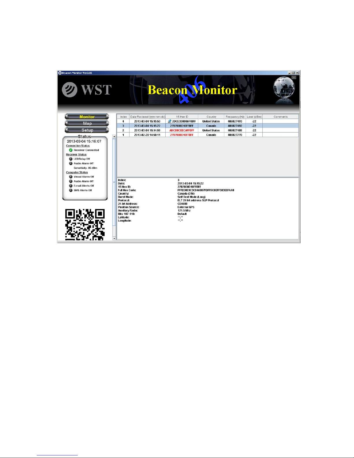
All bursts that are received are logged and recorded. When a burst
is a Normal Mode (Live Burst) the 15 Hex ID will be shown in red
(see Index item #2 below).
Visual Alarm
Normal Mode
(Live Burst)
reception
NOTICE!
All Normal Mode bursts have the potential of being received by the
satellites causing a false alert. If you are confident that a Normal Mode
burst is definitely a false alert and has sufficient power to be received
by the satellites, then contact your local Mission Control Center (MCC).
Refer to the MCC list on page 32 of this Manual.
Page 30

26
Data Files and Log Files:
Each burst will produce an XML file located in Program Files>WS
Technologies Inc>Beacon Monitor>Bursts. When the user deletes
records from the log area on the Monitor page, the corresponding
xml file will automatically be deleted.
Each burst will be added to a log file named Burstlog1.csv, located
in Program Files>WS Technologies Inc>Beacon Monitor>Log. This
file is semi-colon delimited and contains the following information for
each burst: Date; Self Test Flag; Default Hex ID; 30 Hex; Power
(dBm); Frequency; Country; Identifier; Position Flag; Latitude;
Longitude; Beacon Type; Test Protocol Flag; Decode Full details;
Receiver Name; Serial Number; User Latitude; User Longitude;
Temperature; Firmware revision; Software revision.
This file will not be altered when deleting files from the log area on
the Monitor page.
Note: The file must not be kept in use by another application. If the
file is in use by another application (i.e. Excel), when a beacon
burst is received a new file will be generated named Burstlog2.csv.
This ensures data will never be lost.
XML Files
Log File
Page 31

27
FREQUENTLY ASKED QUESTIONS
Q: How do I manually check for software updates?
A: Go to Setup>Help Contents>Updates. Click on the Check for
Updates button.
Q: The computer connected to the Beacon Monitor does not
have internet access. How do I update the software?
A: You can use a different computer to save the software updates to
an external memory device (USB drive, memory card, disk, etc.), so
that you can facilitate the software updates on the target computer.
Go to the Beacon Monitor product page at
www.wst.ca/beacon_monitor.html and click on the FBM200
Software button.
Q: Do I need internet access to run Beacon Monitor?
A: No, however, internet access is required to download and install
the Beacon Monitor application and to send Email or SMS
messaging notifications.
Q: Why does Java need to be installed on my machine?
A: The Beacon Monitor application is written in Java programming
language. The application will not function unless Java is installed.
Q: Why does the temperature of the FBM200 read higher than
the temperature in the room?
A: The temperature reading shows the temperature of the receiver
module inside the Beacon Monitor. It is normal for this temperature
to be about 10ºC above room temperature.
Q: Can I mount the FBM200 outdoors?
A: No. The FBM200 is designed for indoor installation. An optional
outdoor antenna is available.
Q: Why do I not receive any emails (or SMS messages) when I
click Test?
A: If your mail server requires authentication, then you must enter
the account username and password. This applies to both emails
and SMS messaging.
Q: Why doesn’t my receiver show on the map?
A: Go to Setup>Connections and enter the latitude and longitude of
the receiver.
Page 32

28
Q: Can I send emails or SMS messages to more than one
recipient?
A: Yes, the number of email and SMS recipients is unlimited.
Q: I maintain my own database. Can I retrieve the burst
information so I can select the data I want?
A: Yes, there is a log file of all bursts received. This is the
BurstLog1.csv file located in Program Files/WS Technologies
Inc/Beacon Monitor/Log.
Q: Where is the best location to place my receiver?
A: You should place the receiver as far away as possible from away
from sources of electrical noise such as computers, electrical
equipment, etc.
Q: I don’t want other users to be able to change settings. Can I
prevent this?
A: Yes. Go to Setup>Admin-Password>Setup and enable password
protection. Other users will see all of the settings but will not be able
to alter the settings.
Page 33

29
SPECIFICATIONS
O = optional
Minimum Requirements
Windows XP SP3, USB 1.1, Java 7.
FBM200A
SPECIFICATIONS
406 MHz Receiver Sensitivity
-125 dBm
Out of Band Rejection (<400 MHz, >413 MHz)
>145 dB
Harmonic Image Rejection
>95 dB
406 MHz Input Frequency
406.0 – 406.1 MHz
406 MHz RF Input VSWR
1.20:1
406 Input Impedance
50Ω
406 Input Connector
SMA-female RP
Receiver power requirements (from USB port)
+5V @ <500 mA
Operating Temperature Range
-40°C to +85°C
Storage Temperature Range
-55°C to +85°C
Dimensions:
108 x 63 x 26 mm
4.3 x 2.5 x 1.0 inches
Weight:
0.230 kg
0.5 lbs
INCLUDED
USB Cable – (3 m length)
AC to USB Adapter
Ethernet cable (3 m length)
Molded 406 MHz Monopole Antenna
Outdoor 406 MHz Antenna
O
GPS Active Antenna (5 m cable length)
Certificate of Calibration
O
Operator’s Manual
User Interface Software
FEATURES
Receive all Cospas-Sarsat Frequency channels
Decode all Cospas-Sarsat Protocols
Measure 406 MHz Frequency
Measure 406 MHz Receive Power
Adjustable Receiver Sensitivity
USB Interface
Ethernet Interface
GPS Receiver
GPS Antenna
GIS Mapping
Audio and LED Alarms
Alarm Output – relay contacts
BEACON MONITOR
SPECIFICATIONS
Page 34

30
REGULATORY INFORMATION
CANADA
This Class B digital apparatus complies with Canadian ICES-003.
USA
Note: This equipment has been tested and found to comply with the
limits for a Class B digital device, pursuant to part 15 of the FCC
Rules. These limits are designed to provide reasonable protection
against harmful interference in a residential installation. This
equipment generates, uses and can radiate radio frequency energy and, if
not installed and used in accordance with the instructions, may cause
harmful interference to radio communications. However, there is no
guarantee that interference will not occur in a particular installation.
If this equipment does cause harmful interference to radio or television
reception, which can be determined by turning the equipment off and on,
the user is encouraged to try to correct the interference by one or more
of the following measures:
Reorient or relocate the receiving antenna.
Increase the separation between the equipment and receiver.
Connect the equipment into an outlet on a circuit different from that
to which the receiver is connected.
Consult the dealer or an experienced radio/TV technician for help.
This equipment complies with Part 15 of the FCC Rules. Operation is
subject to the following two conditions:
1. This equipment may not cause harmful interference.
2. This equipment must accept any interference that may cause undesired
operation.
Page 35

31
EUROPEAN UNION
Supplier Name: WS Technologies Inc.
Supplier Address: #2 – 215 Neave Road
Kelowna, B.C.
Canada V1V 2L9
Declares under our sole responsibility that the following product
Product Name: 406 Beacon Monitor
Model FBM200
Conforms to the following normative European and International
Standards
Normative: EN 301 489-1 V1.9.2 (2011-09)
Standards: EN 55022:2006
EN 61000-4-2:2008
EN 61000-4-3:2008
EN 61000-4-4:2004
EN 61000-4-5:2005
EN 61000-4-6:2008
EN 61000-4-11:2004
Following the provisions of the normative European Council
Directive 2004/108/EC EMC Directive.
Product conformance to cited product specifications is based on sample (type)
testing, evaluation or assessment at Celltech Labs, Inc. located in Kelowna, British
Columbia, Canada.
Supplementary Information: This product was tested and
complies with all the requirements for the CE Mark.
W.A. Street
President
WS Technologies Inc.
#2 – 215 Neave Road
Kelowna, BC
Canada V1V 2L9
Phone: (250) 765-7583
FAX: (250) 765-1652
DECLARATION OF CONFORMITY
Page 36

32
WARRANTY INFORMATION
WS Technologies Inc. (WST) warrants the products manufactured
by WST to be free from defects in material and workmanship for
one year from the date of shipment. Liability of WST under the
foregoing warranty is limited to the replacement or repair, at the
option of WST, of any products which show defective workmanship
or materials within one year from the date of shipment, which
replacement shall be made FOB WST's facility in Kelowna, BC,
CANADA, upon proof satisfactory to WST of the defect claimed.
Except for the foregoing warranty, WST makes no other warranty,
express or implied, as to the merchantability or fitness for a
particular purpose of products shipped or the performance thereof,
and does not make any warranty to the purchaser's customers or
agents.
CALIBRATION
The Calibration of the FBM200 Beacon Monitor is optional. If
required, the calibration date appears on the Calibration Certificate
supplied with the Beacon Monitor and the Cal Due date appears on
the side of the Beacon Monitor housing.
Before returning a unit for calibration, email returns@wst.ca to
obtain an RMA (Return Materials Authorization) number and
shipping instructions. Once calibrated a new Cal Due date label will
be placed on the unit and a new Calibration Certificate will be
issued.
RETURNS
An RMA (Return Materials Authorization) number must be obtained
by emailing returns@wst.ca . If the unit being returned is not
covered under warranty, a minimum repair charge will apply. If
damage is severe or the products have been tampered with, there
may be additional charges.
Page 37

33
MISSION CONTROL CENTER (MCC) CONTACT INFORMATION
In the event that you believe a Normal Mode (Live Burst) has been
transmitted with sufficient power to cause a false alert, the nearest
Mission Control Centre (MCC) should be contacted. Please refer to
the following list for the MCC in your country.
Country/Region
E-mail
Phone
Fax
Algeria
mcc_alger@mdn.dz
(213.2) 1491647
(213.2) 1491648
Argentina
armcc@sass.gov.ar
(54.11) 44802486
(54.11) 44802486
Australia
rccaus@amsa.gov.au
(61.2) 62306820
(61.2) 62306868
Brazil
brmcc@cindacta1.aer.mil.br
(55.61) 33652964
(55.61) 33652964
Canada
cmcc2@sarnet.dnd.ca
(1.613) 9657265
(1.613) 9657494
Chile
chmcc@fach.cl
(56.2) 9764042
(56.2) 9764043
China
cnmcc@mail.eastnet.com.cn
(86.10) 65293298
(86.10) 65293296
Chinese Taipei
tamcc@ms23.hinet.net
(886.2) 87703661
(886.2) 25450234
France
fmcc@cnes.fr
(33.5) 61254382
(33.5) 61274878
Greece
grmcc@hcg.gr
(30.210) 4191395
(30.210) 4082870
Hong Kong, China
hkmrcc@mardep.gov.hk
(852) 22337999
(852) 25417714
India
inmcc@istrac.org
(91.80) 28094546
(91.80) 28371857
Indonesia
indonesia_mcc@yahoo.com
(62.21) 5501449
(62.21) 5501513
Italy
itmcc247@cospas-sarsatitaly.it
(39.080) 5341571
(39.080) 5342145
Japan
jamcc@kaiho.mlit.go.jp
(81.3) 35916106
(81.3) 35916107
Korea (Republic of)
komcc2@kornet.net
(82.32) 8352594
(82.32) 8352895
Nigeria
mcc@nema.gov.ng
(234) 94134341
(234) 94131749
Norway
mailto@jrcc-bodoe.no
(47) 75559000
(47) 75524200
Pakistan
sckhi@suparco.gov.pk
(92.21) 34690793
(92.21) 34690797
Peru
pemcc@dicapi.mil.pe
(51.1) 4202020
(51.1) 4291547
Russian Federation
cmc@marsat.ru
(7.495) 6261215
(7.495) 6269375
Saudi Arabia
sar-samcc@gaca.gov.sa
(966.2) 6150170
(966.2) 6150171
Singapore
CAAS_RCC@caas.gov.sg
(65) 65425024
(65) 65422548
South Africa
maritimeradio@ixmail.co.za
(27.21) 5529752
(27.21) 5513760
Spain
spmcc@inta.es
(34.928) 727104
(34.928) 727107
Thailand
bkkrcc@aviation.go.th
(66.2) 2860506
(66.2) 2873186
Turkey
trmcc@denizcilik.gov.tr
(90.312) 2313374
(90.312) 2312902
United Arab Emirates
aemcc@uae-jrcc.ae
(971.2) 4056144
(971.2) 4496844
United Kingdom
ukmcc@atlas.co.uk
(44.1309) 616204
(44.1309) 678309
United Kingdom (alt)
-
(44.1309) 678304
(44.1309) 678309
United States
usmcc@noaa.gov
(1.301) 8174576
(1.301) 8174568
Vietnam
vnmcc@vishipel.com.vn
(84.31) 3822181
(84.31) 3842979
Page 38

34
NOTES
Enter important data here for future reference.
Product data
FBM200A serial number: _________________
Date Purchased: _________________
Email data
Outgoing Mail Server: _________________
Outgoing Mail Server Port: _________________
SMTP Username: _________________
SMTP Password: _________________
SMS data
SMS Mail Server: _________________
SMS Mail Sever Port: _________________
SMTP Username: _________________
SMTP Password: _________________
Contacts
Supervisor Contact: _________________
Phone Number: _________________
MCC Contact Name: _________________
Phone Number: _________________
Email Address: _________________
Page 39

35
Notes:
Page 40

36
Notes:
 Loading...