

Page 1

WSMP Solar Water Heater
INSTALLATION MANUAL
WSMP Solar Water Heater made of all-glass evacuated tube collector with heat pipe (Hereinafter
ESWH).
Please take time to read this manual and familiarize yourself with the function of this product.
Content
Introduction ………………………………………….………………………. 2
Specifications of SWH……………………………….………………………. 2
Principle of Operation ……………………………...………………………. 3
Assembly Instructions …………………………………………………….… 3
Reflector Assembly ………………………………………….…………….... 3
Frame Assembly …………………………………………………….………. 3
Connecting frame and reflector …………………………………………. 4
Storage tank assembly ……………………………………………. ……….4
Unit Mounting Instructions …………………………………………………. 4
Mounting on roof ridge ………………………………………... …………..4
Mounting on roof slope ………………………………………... …………..5
Glass Tube Assembly ……………………………………………………….. 6
Evacuated Tubes assembly ……………………………………….. ………6
Precautions …………………………………………………………… ……...8
Plumbing Instructions ……………………………………………………… ..8
User Instructions ……………………………………………………. ………...8
Precautions …………………………………………………………… ………8
Usage and installation ……………………………………………………….9
Trouble Shooting ……………………………………………………………. 10
Introduction of solar water heater
The ESWH are close-coupled solar water systems made of all-glass evacuated
1
Page 2
tube collectors with heat pipes, which are ideal for use in small buildings, houses and other
applications. The ESWH can be used together with an electric booster
element, thus providing hot water even on low-irradiance days. The ESWH is available in several
sizes, depending on your hot water requirements.
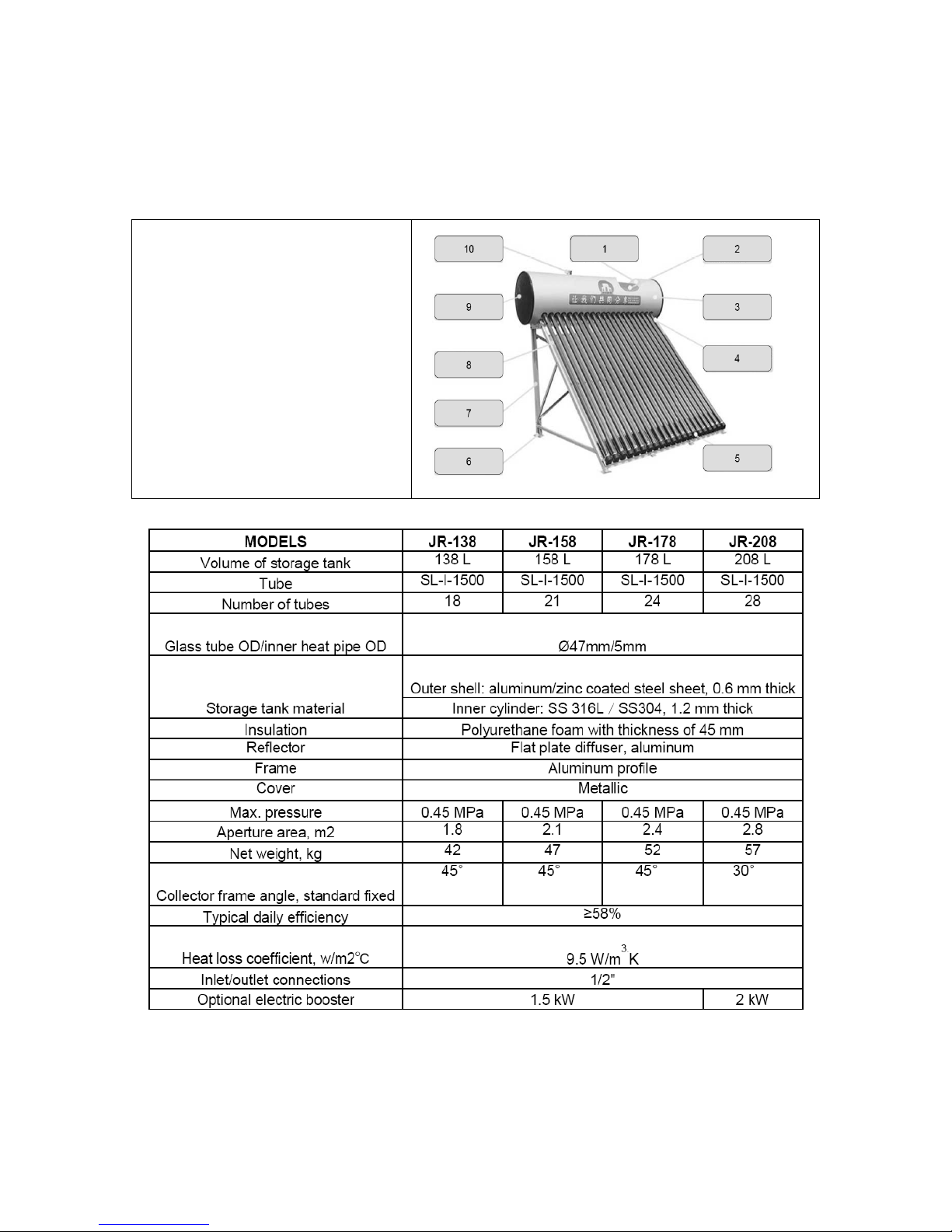
Fig. 1 Structure of ESWH
1 Insulation: polyurethane foam
2 Inner cylinder: AISI 316L
3 Outer shell: galvanized steel
4 Heat pipe in contact with aluminium
fin
5 End protector: nylon 6
6 Foot: stainless steel
7 Frame: profile aluminium
8 Reflector: flat plate diffuser
9 Side ends: metallic
10 Relief valve
Specification of ESWH
2
Page 3
Operational Principle
The ESWH are all-glass evacuated solar domestic water systems
combined with heat pipes. The selective coating in the inner cover of the evacuated tubes ensures
high energy absorption and low heat radiance losses, which converts solar energy into heat energy
and transfers this energy to the heat pipe by an aluminium fin. The liquid in the heat pipe changes
into vapour and rises to the condenser. The heat conducts away to the water inside the tank and
the vapour in the heat pipe again becomes liquid, returning to the base of the heat pipe. This
continuous circulation transfers heat from the heat pipe to the cold water in the tank. This process
will continue as long as the sun is heating the collectors.
Assembly Instruction
The reflector angle of ESWH heater can be chosen between 30°or 45°.
Reflector Assembly
1. Place the module-type reflectors side by side.
2. Position the base bracket with larger parallel slots at the bottom. Overlap the holes with those in
the triangular end of reflector frame. Fasten with the nuts and bolts provided.
3. Position the narrow sides of the top reflector bar upwards and overlap the holes with those in the
square end of the reflector frame. Fasten with the nuts and bolts provided.
Frame Assembly
Cross-connect the diagonal bars with the right and left upright supports.
In the JR-200 model, connect the two sets of crossed diagonal bars to the middle upright support.
Then connect to right and left upright supports.
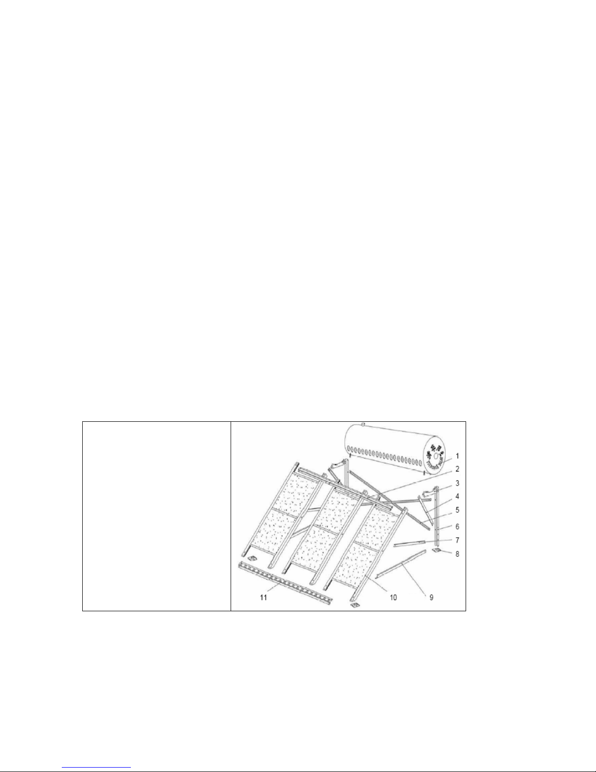
1 tank
2 top reflector bar
3 tank bracket
4 upward diagonal bar
5 diagonal bar of upright support
6 upright support
7 mid-diagonal sidebar
8 foot
9 bottom sidebar
10 reflector
11 base bracket
Fig. 2 Assembly of the unit (the collector tilt angle is 30°and 45°respectively)
3
Page 4
Assembly Frame and Reflector
1. Face the flat surface of tank bracket outwards.
2. Insert tank bracket between top reflector bar and reflector frame, at the same time overlapping
holes. Fasten with the nuts and bolts provided.
3. Fasten other end of tank bracket to right and left upright supports.
4. 45º collector angle: fasten diagonal sidebars and bottom sidebars.
30º collector angle: fasten 4 diagonal sidebars and bottom sidebars.
5. Attach the 4 feet.
Storage tank assembly
1. Place tank onto tank bracket cradle, inserting protruding bolts into holes. Fasten with nuts.
2. Screw the air vent into place.
NOTE: Leave the nuts loose as some alignment/adjustment may be necessary after fitting tubes.
Unit Mounting Instructions
Mounting on the roof ridge
The assembled unit should be placed on the roof ridge, move the unit from south to north to adjust
the collector tilt angle, and ensures that the overflow pipe and inlet/outlet is vertical to the Horizon.
This is recommended only on roofs with slopes of between 21°and 40°.
Note: Remove diagonal sidebars if ridge cap impedes them. Ensure other attachments can
compensate for lack of diagonal sidebars.
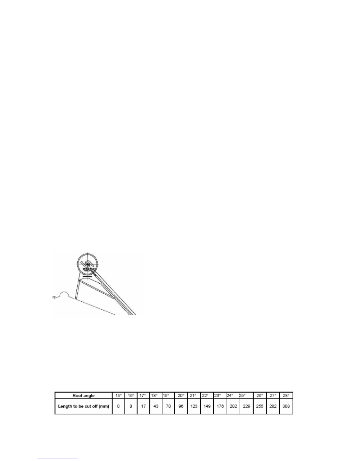
Mounting on the roof slope
Determine roof angle.
Cut the right and left upright supports as specified in tab. 2.
Check tank is parallel with the ground, inlet/outlet pipes vertical.
Tab. 2 cutting upright supports instructions
4
Page 5
NOTE:
1. Place the assembled unit on the North-facing slope of the roof for use in the Southern
Hemisphere.
2. Ensure tank is parallel with the ground, and inlet/outlet pipes vertical. (refer to table below for
details)
3. Attach system securely to the roof either by 6 mm steel wires or if ground mounted, the frame
fastened to metal attachment points (not supplied) encased in cement blocks. (dimensions of each
block 100×100×h (h≥50) mm). Both methods should be used in areas of high wind.
4. Connect inlet/outlet pipes to internal plumbing.
5. Insulate all external pipes and wrap in insulating foil.
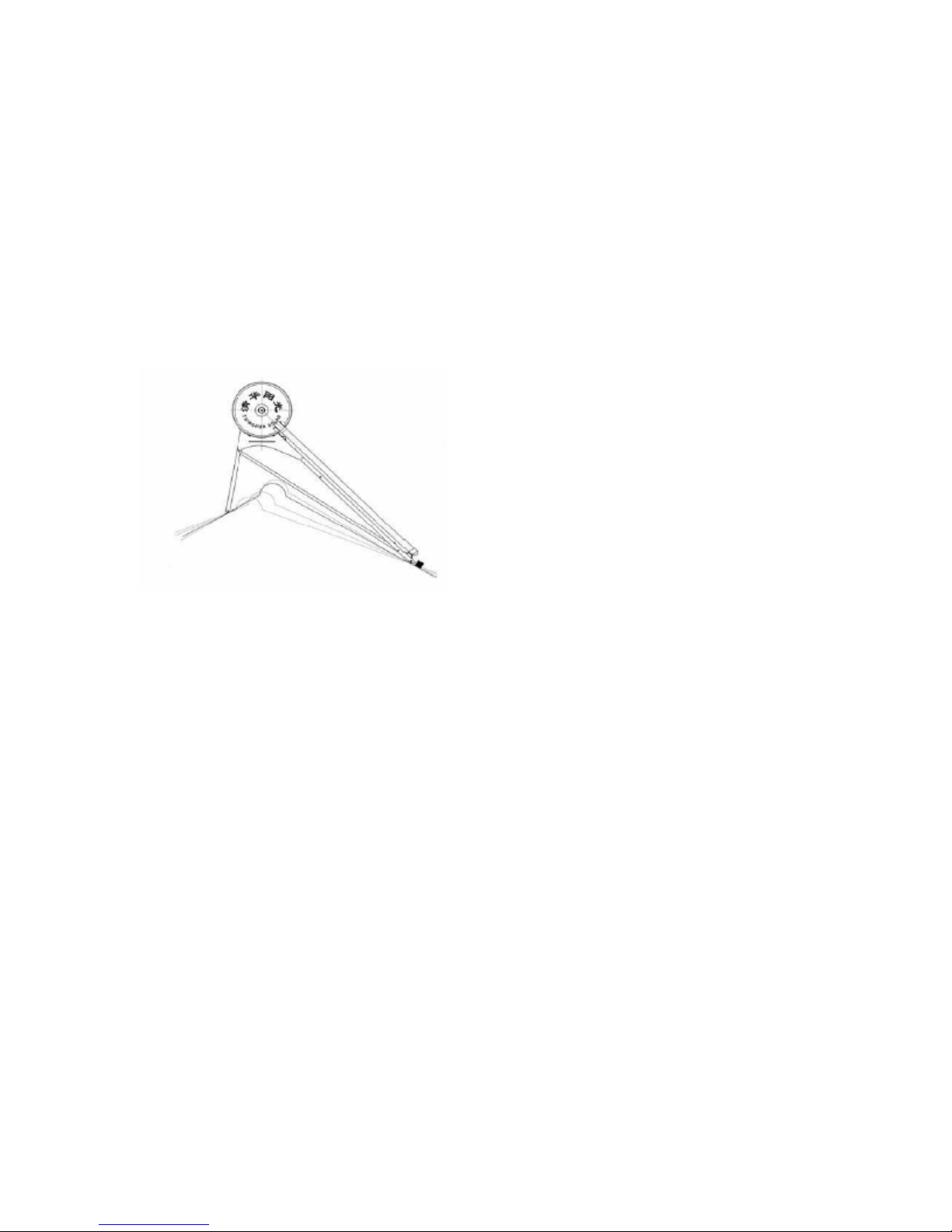
Fig. 3 Unit mounted on the roof ridge
5
Page 6
Glass Tube Assembly
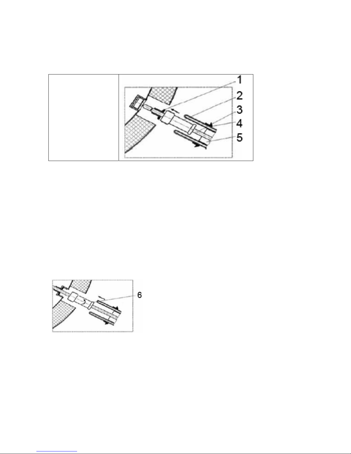
Evacuated Tubes Assembly
1 Seal
2 Connections
3 Heat pipe
4 Black rubber seal
5 Aluminium fin
1. Place the o rings into the recess on the copper heat pipes at the end with the large bulb.
2. Fit a black rubber wind-blocking seal to the open end of the glass tubes and take note of which
end should slide into the recess in the tank. It will be easier to do this if the tube is moistened for
lubrication. Slide the seal 10 cm down the tube.
3. Slide the threaded brass securing bush over the bottom of the heat pipe, insert the long thin end
of the heat pipe into the aluminium fin already in the evacuated tube, leaving enough of the heat
pipe exposed to allow insertion of the heat pipe into the tank and for fastening of the threaded
brass securing bush.
4. Insert the heat pipe into the locating hole in the tank, and tighten up the brass locating bush of
the heat pipe into the recess in the tank with enough pressure to effect a seal, but do not over
tighten.
5. Push the glass tube into the locating hole in the tank; do not twist the tube to avoid damaging the
inner cover of the tube.
6. Insert the tubes end into the end protector, and then clip the protector first into the shorter holes
in the tube carriage, and then the left/right flexible fasteners into the longer holes in the tube
carriage.
6
Page 7
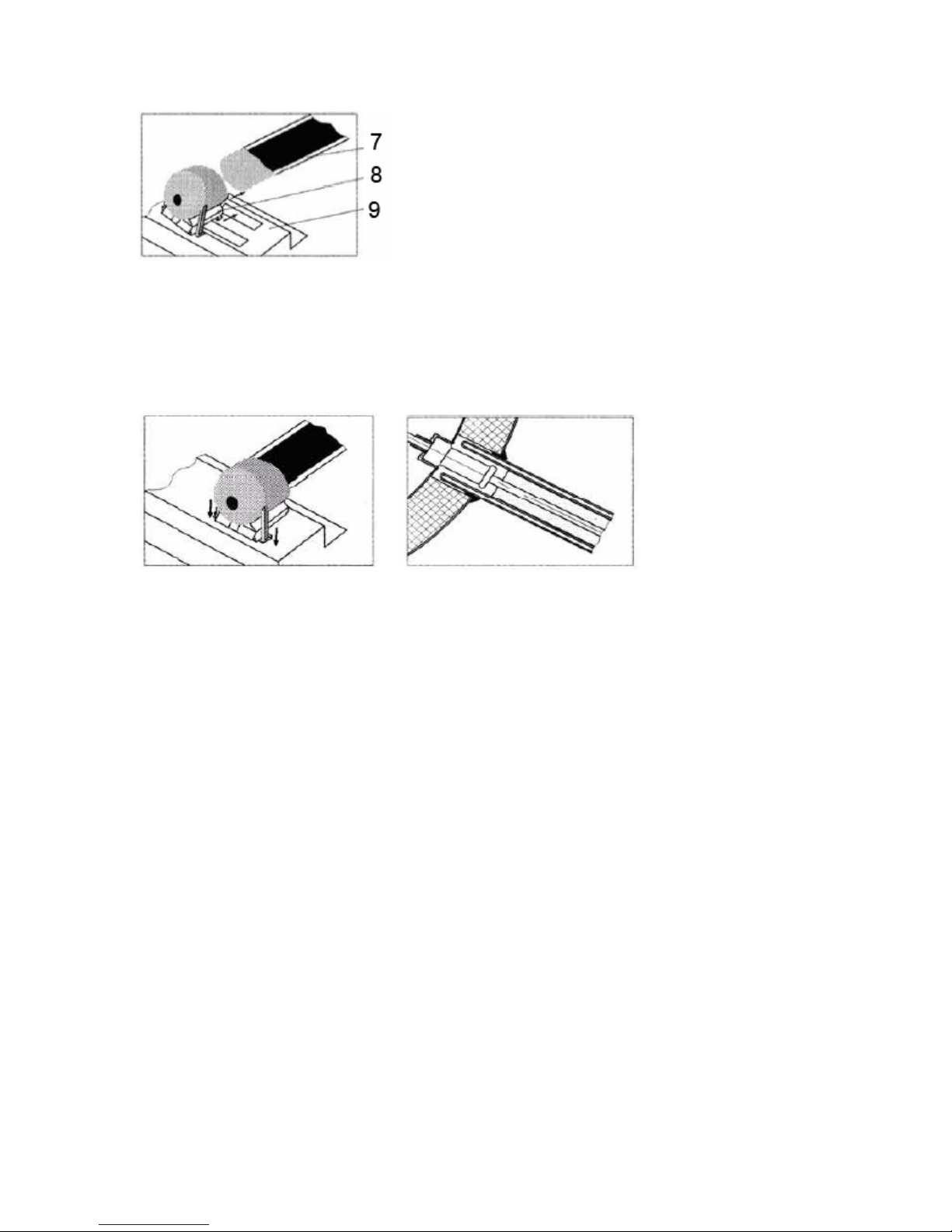
7. Slide the black rubber wind- blocking seals up the tube until the lip on the seal is flush with the
tank.
8. Insert all tubes to achieve alignment of the tank and the frame before fastening the frame nuts
and bolts.
9. Once fully assembled tighten all nuts and bolts.
Precautions:
1. Do not assemble in the sun unless the glass tubes are covered, the heat pipes can get hot
enough to cause a burn injury, and damage to the heat pipes will occur if the hot end of the pipe
contacts cold water. Only uncover the glass tubes once the tank is filled with water.
2. Do not bend, distort or crush the copper heat pipe.
3. Do not allow the copper joint of heat pipe to impact on the evacuated tubes during installation
4. Do not untwist the copper joint of the heat pipe; it was sealed in the factory, and allowing the
liquid inside to escape will render the heat pipe useless.
7
Page 8
Plumbing Instructions
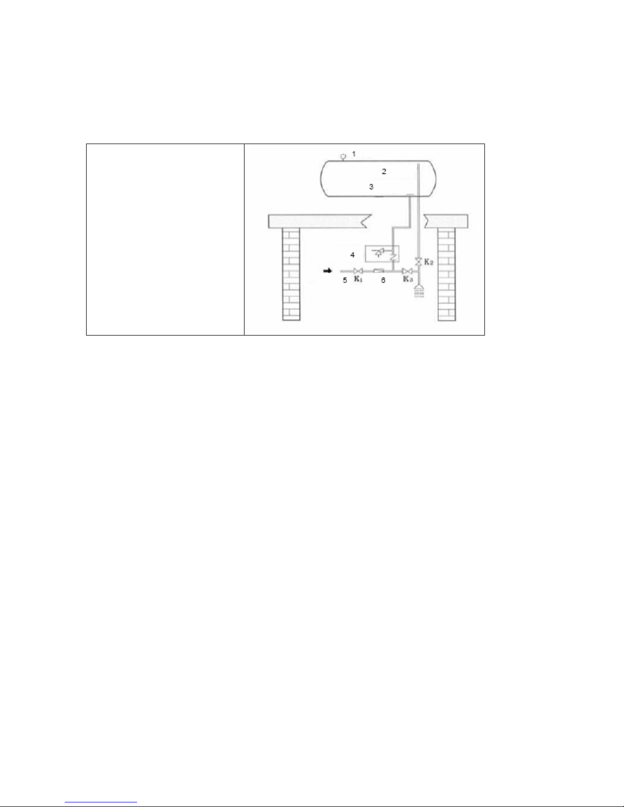
For ESWH, the optional auxiliary electric controller functions as a pump control,
Electric heating element control and a timer. The optional auxiliary electric controller is not
displayed in Fig. 8.
1 air vent
2 hot water outlet pipe
3 water-blocking board (drip tray)
4 pressure relief valve
5 cold water inlet
6 pressure reducing valve
Instructions:
Valve k1remains open, valve k2,k3 remain closed when hot water is not used.
Open valve k2when hot water is to be used, open valve k3 to adjust the water temperature if it is
too hot.
Close valve k2, k3when you want to stop using the hot water.
Precautions:
1. When the hot water is to be used, beware of scalding as the water temperature can be very
high. Mix with cold water to achieve comfortable temperature before showering or bathing.
2. JB series solar water heater withstands pressure ≤0.5 kgf/cm
3. The evacuated tubes resist temperatures as low as -70 when the tank is empty. Under these
conditions, for the unit without auxiliary electric controller, the tank should remain filled during
continuously cloudy or snowing days in winter; in addition, every two days the cold water in the
tank should be changed to prevent the water in the tank from freezing which might damage the
tubes.
4. Make sure the evacuated tubes are clean, hose off the dust and dirt on the tubes and the
reflector before the winter.
5. Do not fill with cold water more than once in a low solar irradiance day.
6. The overflow pipe must be connected outdoors; the overflow pipe should be placed near a floor
drain or drainage channel, the overflow pipe should never be blocked.
7. Do not connect a valve in the overflow pipe line.
8. Avoid using hot water from the unit washing machines.
8
Page 9

Usage and installation FAQ
- What are the most obvious advantages of a ESWH?
• Can be installed individually or combined with a traditional system;
• Withstand pressure;
• Can operate with occasional tube breakages and these can be replaced easily;
• Works well in low-irradiance day with an electric booster
- How to avoid cold water and hot water mixing?
• If the outflow rate is limited within 8L/min, this mixing can be avoided.
- How to clean lime off heat pipes if they have been used for a long time?
• Carefully remove collector tubes, screw loose the heat pipe, clean the top end with
chemical decontaminant.
- Why does hot water flow intermittently some times?
• When the outflow rate is greater than the inflow, the relief valve on the top of tank will open
and suck air in; the water level inside the tank will then be temporarily lower than the outlet
connection, so hot water flow will stop.
• It is recommended that more than two showers or hot taps shall not be used at the same
time.
- Where to install pressure-reducing valve and safety valve?
• The pressure-reducing valve can be installed outside near the cold water connection on
the bottom of the storage tank. But the safety valve shall be installed indoors.
- What are the requirements for the piping and connections?
• Choose good aluminium and plastic compounds with heat-resistance over 90°C.
And ask your local professionals to install your solar water heater.
9
Page 10
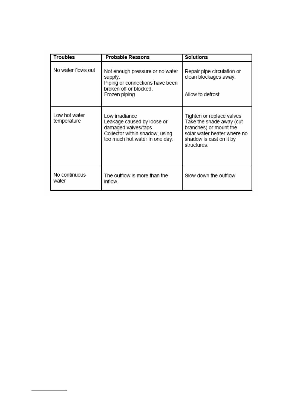
Trouble Shooting
10
 Loading...