

Page 1
WORKSHOP MANUAL
KiSC issued 01, 2009 A
DIESEL ENGINE
V3307-DI-T-E2B
Page 2

TO THE READER
KiSC issued 01, 2009 A
This Workshop Manual has been prepared to provide servicing personnel with
information on the mechanism, service and maintenance of V3307-DI-T-E2B. It is
divided into three parts, “General”, “Mechanism” and “Servicing”.
Q General
Information on the engine identification, the general precautions, maintenance check
list, check and maintenance and special tools are described.
Q Mechanism
Information on the construction and function are included. This part should be
understood before proceeding with troubleshooting, disassembling and servicing.
Refer to Diesel Engine Mechanism Workshop Manual (Code No. 9Y021-01876) for
the one which has not been described to this workshop manual.
Q Servicing
Information on the troubleshooting, servicing specification lists, tightening torque,
checking and adjusting, disassembling and assembling, and servicing which cover
procedures, precautions, factory specifications and allowable limits.
All information illustrations and specifications contained in this manual are based on
the latest product information available at the time of publication.
The right is reserved to make changes in all information at any time without notice.
Due to covering many models of this manual, information or picture being used, have
not been specified as one model.
© KUBOTA Corporation 2008
December 2008
Page 3
V3307-DI-T-E2B, WSM
KiSC issued 01, 2009 A
SAFETY INSTRUCTIONS
SAFETY INSTRUCTIONS
SAFETY FIRST
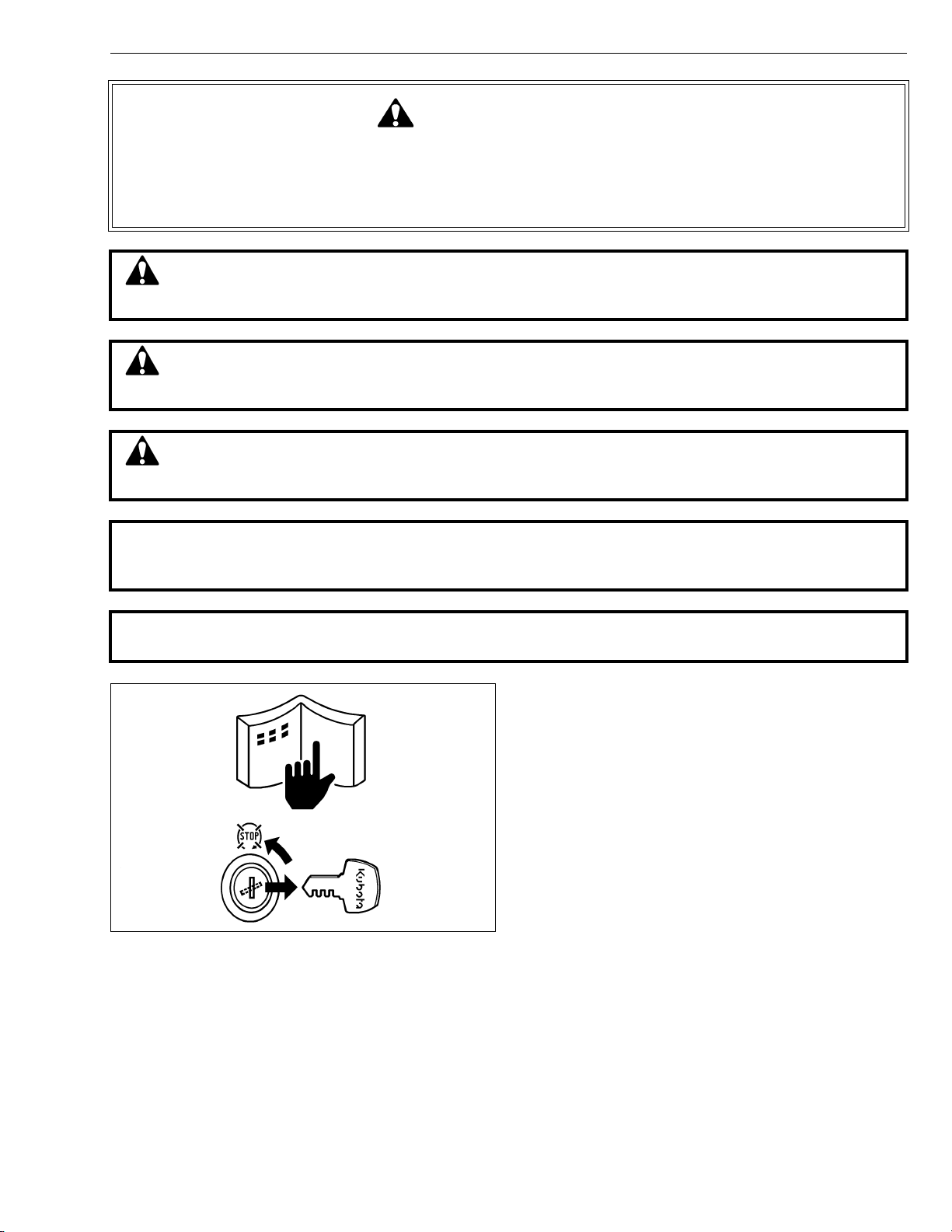
This symbol, the industry’s “Safety Alert Symbol”, is used throughout this manual and on labels on
the machine itself to warn of the possibility of personal injury. Read these instructions carefully.
It is essential that you read the instructions and safety regulations before you attempt to repair or use
this unit.
DANGER : Indicates an imminently hazardous situation which, if not avoided, will result in
death or serious injury.
WARNING : Indicates a potentially hazardous situation which, if not avoided, could result in
death or serious injury.
CAUTION : Indicates a potentially hazardous situation which, if not avoided, may result in
minor or moderate injury.
Q IMPORTANT : Indicates that equipment or property damage could result if instructions are not
followed.
Q NOTE : Gives helpful information.
BEFORE SERVICING AND REPAIRING
• Read all instructions and safety instructions in this
manual and on your engine safety decals.
• Clean the work area and engine.
• Park the machine on a firm and level ground.
• Allow the engine to cool before proceeding.
• Stop the engine, and remove the key.
• Disconnect the battery negative cable.
• Hang a “DO NOT OPERATE” tag in operator
station.
1
Page 4
V3307-DI-T-E2B, WSM
KiSC issued 01, 2009 A
SAFETY INSTRUCTIONS
SAFETY STARTING
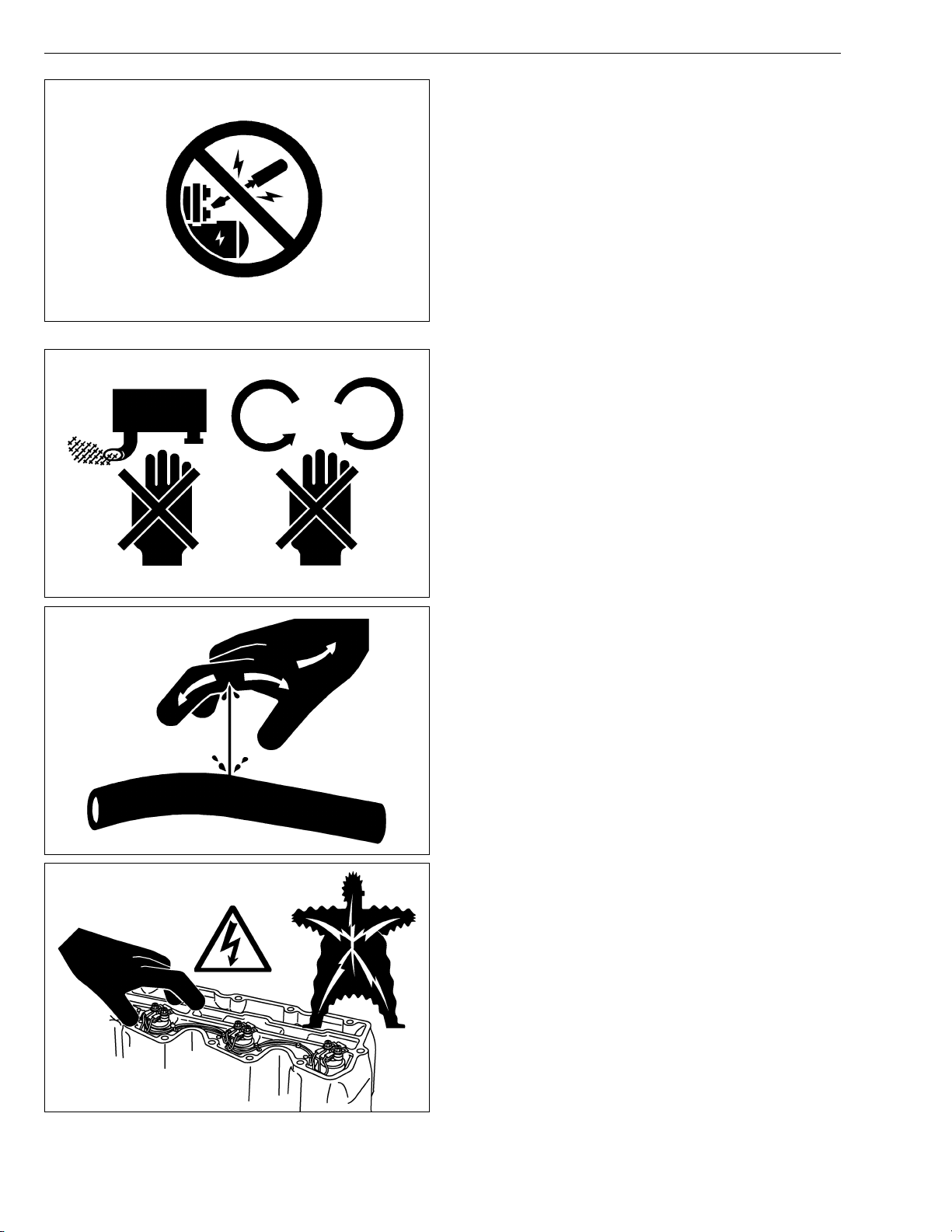
• Do not start the engine by shorting across starter
terminals or bypassing the safety start switch.
• Unauthorized modifications to the engine may impair
the function and / or safety and affect engine life.
SAFETY WORKING
• Do not work on the machine while under the influence
of alcohol, medication, or other substances or while
fatigued.
• Wear close fitting clothing and safety equipment
appropriate to the job.
• Use tools appropriate to the work. Makeshift tools,
parts, and procedures are not recommended.
• When servicing is performed together by two or more
persons, take care to perform all work safely.
• Do not touch the rotating or hot parts while the engine
is running.
• Never remove the radiator cap while the engine is
running, or immediately after stopping. Otherwise, hot
water will spout out from radiator. Only remove
radiator cap when cool enough to touch with bare
hands. Slowly loosen the cap to first stop to relieve
pressure before removing completely.
• Escaping fluid (fuel or hydraulic oil) under pressure
can penetrate the skin causing serious injury. Relieve
pressure before disconnecting hydraulic or fuel lines.
Tighten all connections before applying pressure.
• Wear a suitable hearing protective device such as
earmuffs or earplugs to protect against objectionable
or uncomfortable loud noises.
• Do not open high-pressure fuel system.
High-pressure fluid remaining in fuel lines can cause
serious injury. Do not disconnect or attempt to repair
fuel lines, sensors, or any other components between
the high-pressure fuel pump and injectors on engines
with high pressure common rail fuel system.
• High voltage exceeding 100 V is generated in the
ECU, and is applied to the injector.
Pay sufficient caution to electric shock when
performing work activities.
2
Page 5
V3307-DI-T-E2B, WSM
KiSC issued 01, 2009 A
SAFETY INSTRUCTIONS
AVOID FIRES
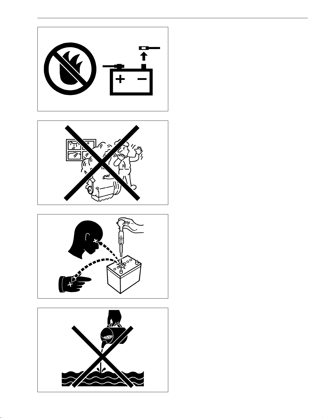
• Fuel is extremely flammable and explosive under
certain conditions. Do not smoke or allow flames or
sparks in your working area.
• To avoid sparks from an accidental short circuit,
always disconnect the battery negative cable first and
connect it last.
• Battery gas can explode. Keep sparks and open
flame away from the top of battery, especially when
charging the battery.
• Make sure that no fuel has been spilled on the engine.
VENTILATE WORK AREA
• If the engine must be running to do some work, make
sure the area is well ventilated. Never run the engine
in a closed area. The exhaust gas contains poisonous
carbon monoxide.
PREVENT ACID BURNS
• Sulfuric acid in battery electrolyte is poisonous. It is
strong enough to burn skin, clothing and cause
blindness if splashed into eyes. Keep electrolyte
away from eyes, hands and clothing. If you spill
electrolyte on yourself, flush with water, and get
medical attention immediately.
DISPOSE OF FLUIDS PROPERLY
• Do not pour fluids into the ground, down a drain, or
into a stream, pond, or lake. Observe relevant
environmental protection regulations when disposing
of oil, fuel, coolant, electrolyte and other harmful
waste.
3
Page 6
V3307-DI-T-E2B, WSM
KiSC issued 01, 2009 A
SAFETY INSTRUCTIONS
PREPARE FOR EMERGENCIES
• Keep a first aid kit and fire extinguisher handy at all
times.
• Keep emergency numbers for doctors, ambulance
service, hospital and fire department near your
telephone.
4
Page 7
V3307-DI-T-E2B, WSM
KiSC issued 01, 2009 A
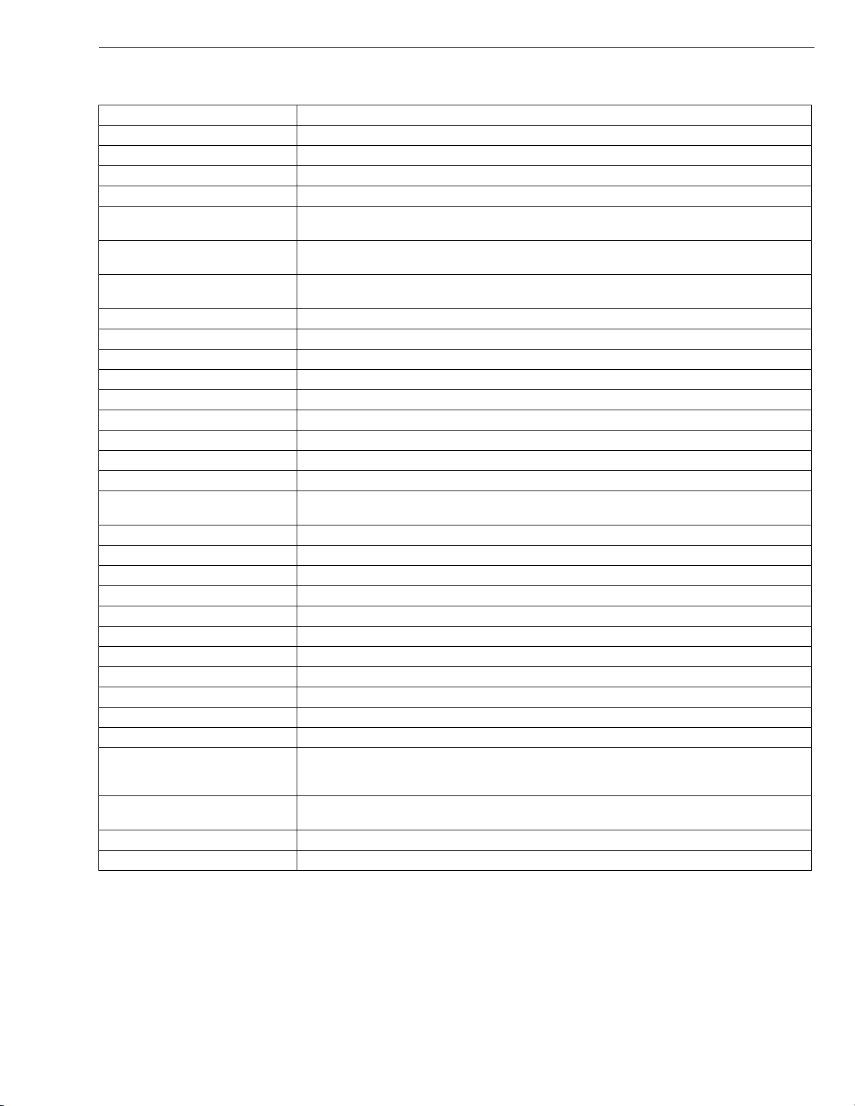
SPECIFICATIONS
Model V3307-DI-T-E2B
Number of Cylinder 4
Type Vertical, water-cooled, 4-cycle DI diesel engine
Bore × Stroke 94.0 × 120 mm (3.70 × 4.72 in.)
Total Displacement 3331 cm
ISO Net Continuous
ISO / SAE Net Intermittent
SAE Gross Intermittent
47.1 kW / 2600 min
(63.2 HP / 2600 min
53.7 kW / 2600 min
(72.0 HP / 2600 min
55.4 kW / 2600 min
(74.3 HP / 2600 min
Maximum Bare Speed 2820 min
Minimum Bare Idling Speed 775 to 825 min
Combustion Chamber Reentrant Type, Center Direct Injection Type (E-CDIS)
Fuel Injection Pump Bosch PFR4KZ Type Mini Pump
Governor All speed mechanical governor
Direction of Rotation Counter-clockwise (Viewed from flywheel side)
Injection Nozzle Bosch P Type
Injection Timing 0.0087 rad (0.50 °) after T.D.C.
Firing Order 1-3-4-2
Injection Pressure
1st stage 18.63 MPa (190.0 kgf/cm
2nd stage 22.56 MPa (230.0 kgf/cm
Compression Ratio 20.0
Lubricating System Forced lubrication by trochoid pump
Oil Pressure Indicating Electrical Type Switch
Lubricating Filter Full Flow Paper Filter (Cartridge Type)
Cooling System Pressurized radiator, forced circulation with water pump
Starting System Electric Starting with Starter
Starting Motor 12 V, 3.0 kW
Starting Support Device By Glow Plug in Combustion Chamber
EGR None
Battery 12 V, 120 AH equivalent
Charging Alternator 12 V, 540 W
Recommended fuels vary depending on the contents of the emission control regulations, the ambient
Fuel
Lubricating Oil
temperature, and the fuel specifications. Therefore, please refer to the detailed description on page
Class CF lubricating oil as per API classification is recommended.
For details on recommended lubricating oils, see page G-6 and page G-9.
Lubricating Oil Capacity 11.2 L (2.96 U.S.gals)
Weight (Dry) 271 kg (597 lbs)
* The specification described above is of the standard engine of each model.
* Conversion Formula : HP = 0.746 kW, PS = 0.7355 kW
3
(203.3 cu.in.)
-1
-1
-1
-1
-1
-1
-1
(rpm)
-1
(rpm)
G-6.
(rpm)
(rpm))
(rpm)
(rpm))
(rpm)
(rpm))
2
2
, 2702 psi),
, 3271 psi),
SPECIFICATIONS
W1028103
5
Page 8
V3307-DI-T-E2B, WSM
KiSC issued 01, 2009 A
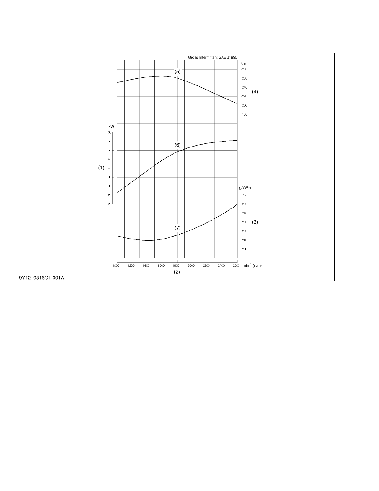
PERFORMANCE CURVES
Q V3307-DI-T-E2B
PERFORMANCE CURVES
(1) Brake Horsepower
(2) Engine Speed
(3) B.S.F.C.
(4) Torque
(5) Gross Intermittent Torque
(6) Gross Intermittent B.H.P.
(7) Gross Intermittent B.S.F.C.
6
Page 9
V3307-DI-T-E2B, WSM
KiSC issued 01, 2009 A
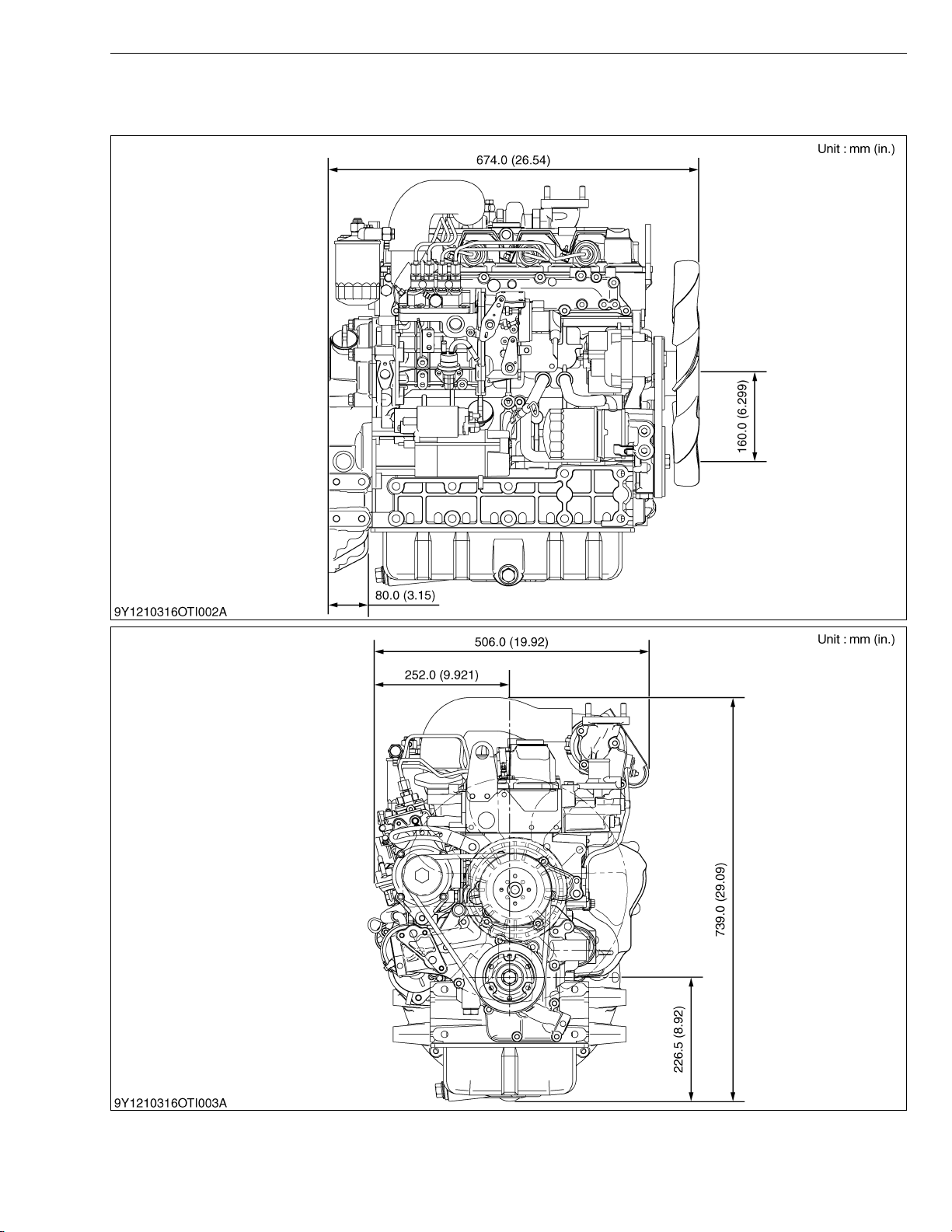
DIMENSIONS
Q V3307-DI-T-E2B
DIMENSIONS
7
Page 10

GENERAL
KiSC issued 01, 2009 A
CONTENTS
1. ENGINE IDENTIFICATION ............................................................................. G-1
[1] MODEL NAME AND ENGINE SERIAL NUMBER ................................ G-1
[2] E2B ENGINE............................................................................................. G-3
[3] CYLINDER NUMBER ............................................................................... G-3
2. GENERAL PRECAUTIONS ............................................................................ G-4
3. MAINTENANCE CHECK LIST ....................................................................... G-5
4. CHECK AND MAINTENANCE ....................................................................... G-7
[1] DAILY CHECK POINTS........................................................................... G-7
[2] CHECK POINTS OF INITIAL 50 HOURS ............................................. G-9
[3] CHECK POINT OF EVERY 50 HOURS ............................................. G-11
[4] CHECK POINTS OF EVERY 250 HOURS......................................... G-12
[5] CHECK POINTS OF EVERY 500 HOURS......................................... G-14
[6] CHECK POINT OF EVERY 1000 HOURS ......................................... G-17
[7] CHECK POINTS OF EVERY 1 OR 2 MONTHS ............................... G-18
[8] CHECK POINTS OF EVERY 1500 HOURS....................................... G-20
[9] CHECK POINTS OF EVERY 3000 HOURS....................................... G-21
[10]CHECK POINTS OF EVERY 1 YEAR ................................................ G-24
[11]CHECK POINTS OF EVERY 2 YEARS.............................................. G-25
5. SPECIAL TOOLS.......................................................................................... G-28
Page 11
V3307-DI-T-E2B, WSM
KiSC issued 01, 2009 A
1. ENGINE IDENTIFICATION
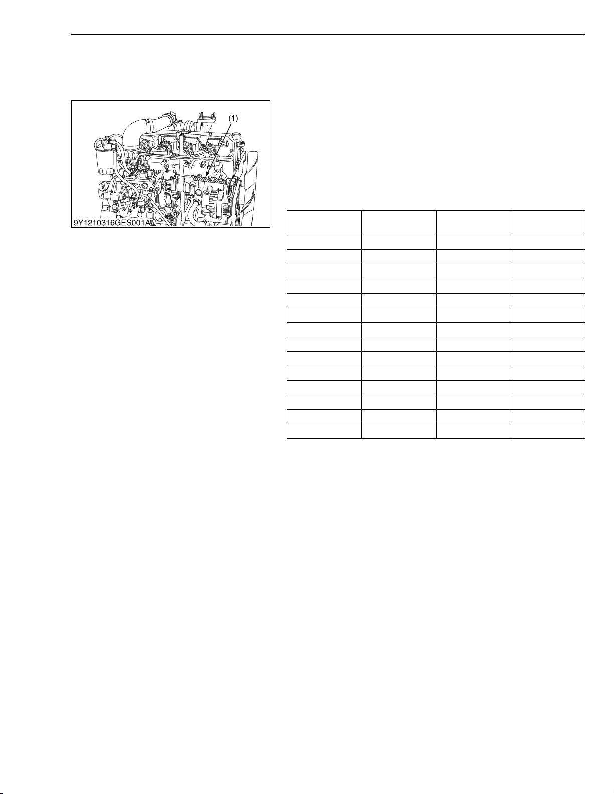
[1] MODEL NAME AND ENGINE SERIAL NUMBER
When contacting the manufacture, always specify your engine
model name and serial number.
The engine model and its serial number need to be identified
before the engine can be serviced or parts replaced.
Q Engine Serial Number
The engine serial number is an identified number for the engine.
It is marked after the engine model number.
It indicates month and year of manufacture as follows.
• Year of manufacture
Alphabet or
Number
1 2001 F 2015
2 2002 G 2016
3 2003 H 2017
4 2004 J 2018
5 2005 K 2019
6 2006 L 2020
7 2007 M 2021
8 2008 N 2022
9 2009 P 2023
A 2010 R 2024
B 2011 S 2025
C 2012 T 2026
D 2013 V 2027
E 2014
Year
Alphabet or
Number
G GENERAL
Yea r
(1) Engine Model Name and Serial
Number
W1010477
G-1
Page 12
V3307-DI-T-E2B, WSM
KiSC issued 01, 2009 A
G GENERAL
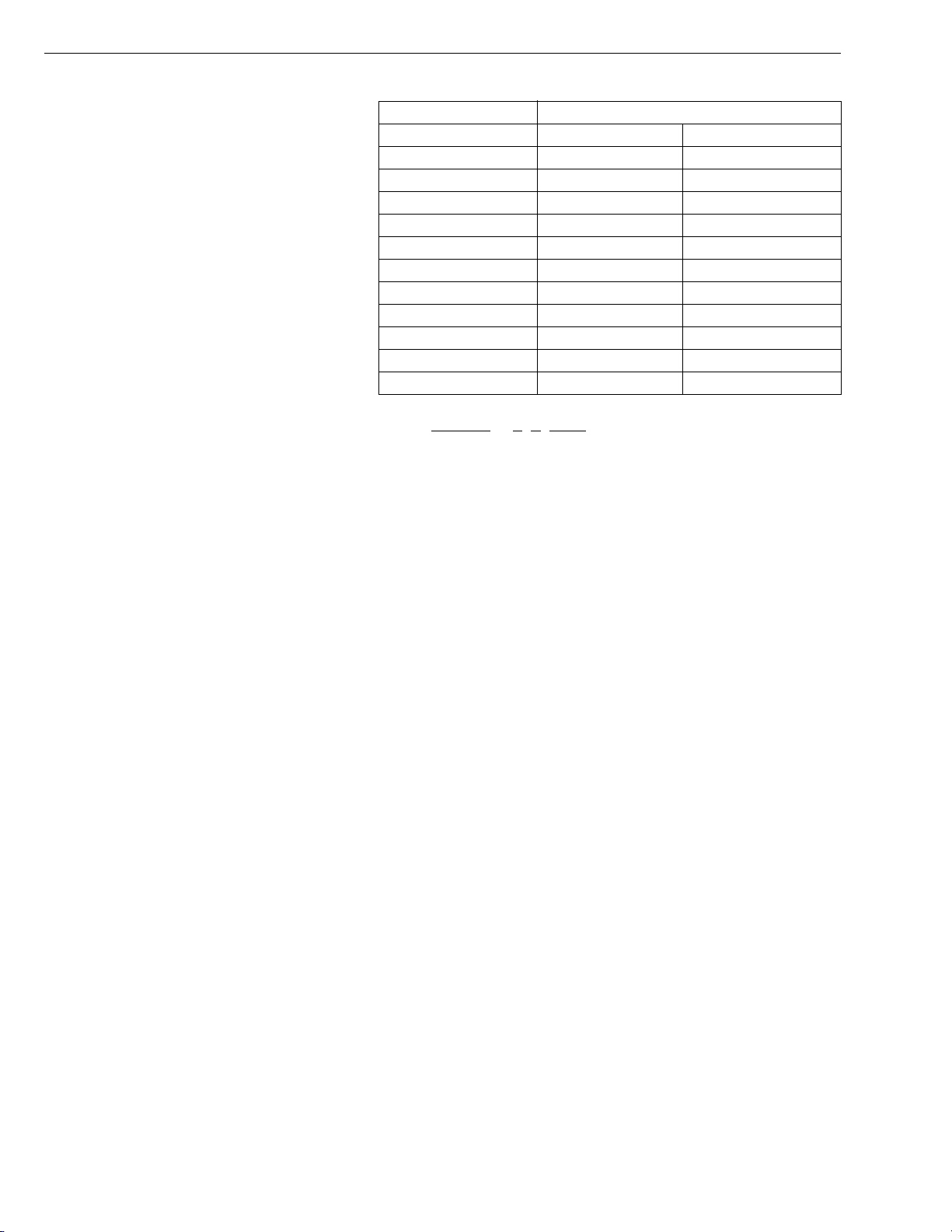
• Month of manufacture
Month Engine Lot Number
January A0001 ~ A9999 B0001 ~ BZ999
February C0001 ~ C9999 D0001 ~ DZ999
March E0001 ~ E9999 F0001 ~ FZ999
April G0001 ~ G9999 H0001 ~ HZ999
May J0001 ~ J9999 K0001 ~ KZ999
June L0001 ~ L9999 M0001 ~ MZ999
July N0001 ~ N9999 P0001 ~ PZ999
August Q0001 ~ Q9999 R0001 ~ RZ999
September S0001 ~ S9999 T0001 ~ TZ999
October U0001 ~ U9999 V0001 ~ VZ999
November W0001 ~ W9999 X0001 ~ XZ999
December Y0001 ~ Y9999 Z0001 ~ ZZ999
* Alphabetical letters “I” and “O” are not used.
e.g. V3307-T
- 7 V A001
(a) (b)(c) (d)
(a) Engine Model Name : V3307-DI-T
(b) Year : 7 indicates 2007
(c) Month : U or V indicates October
(d) Lot number : (0001 ~ 9999 or A001 ~ Z999)
W1024938
G-2
Page 13
V3307-DI-T-E2B, WSM
KiSC issued 01, 2009 A
G GENERAL
[2] E2B ENGINE
[Example : Engine Model Name V3307-DI-T-E2B-XXXX]
The emission controls that have been put into effect in various countries to prevent air pollution will be stepped up.
The time to enforce the regulations differs depending on the engine output classifications.
Kubota has been supplying the diesel engines conforming to the emission regulations in respective countries.
Exhaust emissions regulations shift to the second stage. Kubota executed the improvement of the engine according
to this regulation.
In order to discriminate the engines conforming to Tier 1 / Phase 1 requirements and those conforming to Tier 2 /
Phase 2 requirements, we have adopted E2B as a new model name for the engines conforming Tier 2 / Phase 2
regulations.
In the after-sale services for 07-E2B series engines, only use the dedicated parts for E2B models and carry out the
maintenance services accordingly.
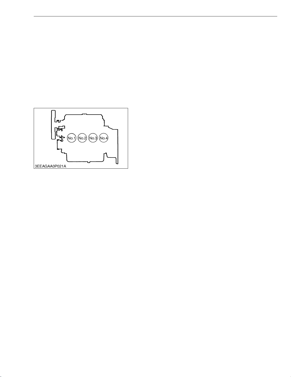
[3] CYLINDER NUMBER
The cylinder numbers of kubota diesel engine are designated as
shown in the figure.
The sequence of cylinder numbers is given as No. 1, No. 2,
No. 3 and No. 4 starting from the front cover side.
W1011077
G-3
Page 14
V3307-DI-T-E2B, WSM
KiSC issued 01, 2009 A
2. GENERAL PRECAUTIONS
• During disassembly, carefully arrange removed parts in a clean
area to prevent confusion later. Screws, bolts and nuts should be
replaced in their original position to prevent reassembly errors.
• When special tools are required, use KUBOTA genuine special
tools. Special tools which are not frequently used should be
made according to the drawings provided.
• Before disassembling or servicing live wires, make sure to
always disconnect the grounding cable from the battery first.
• Remove oil and dirt from parts before measuring.
• Use only KUBOTA genuine parts for parts replacement to
maintain engine performance and to ensure safety.
• Gaskets and O-rings must be replaced during reassembly.
Apply grease to new O-rings or oil seals before assembling.
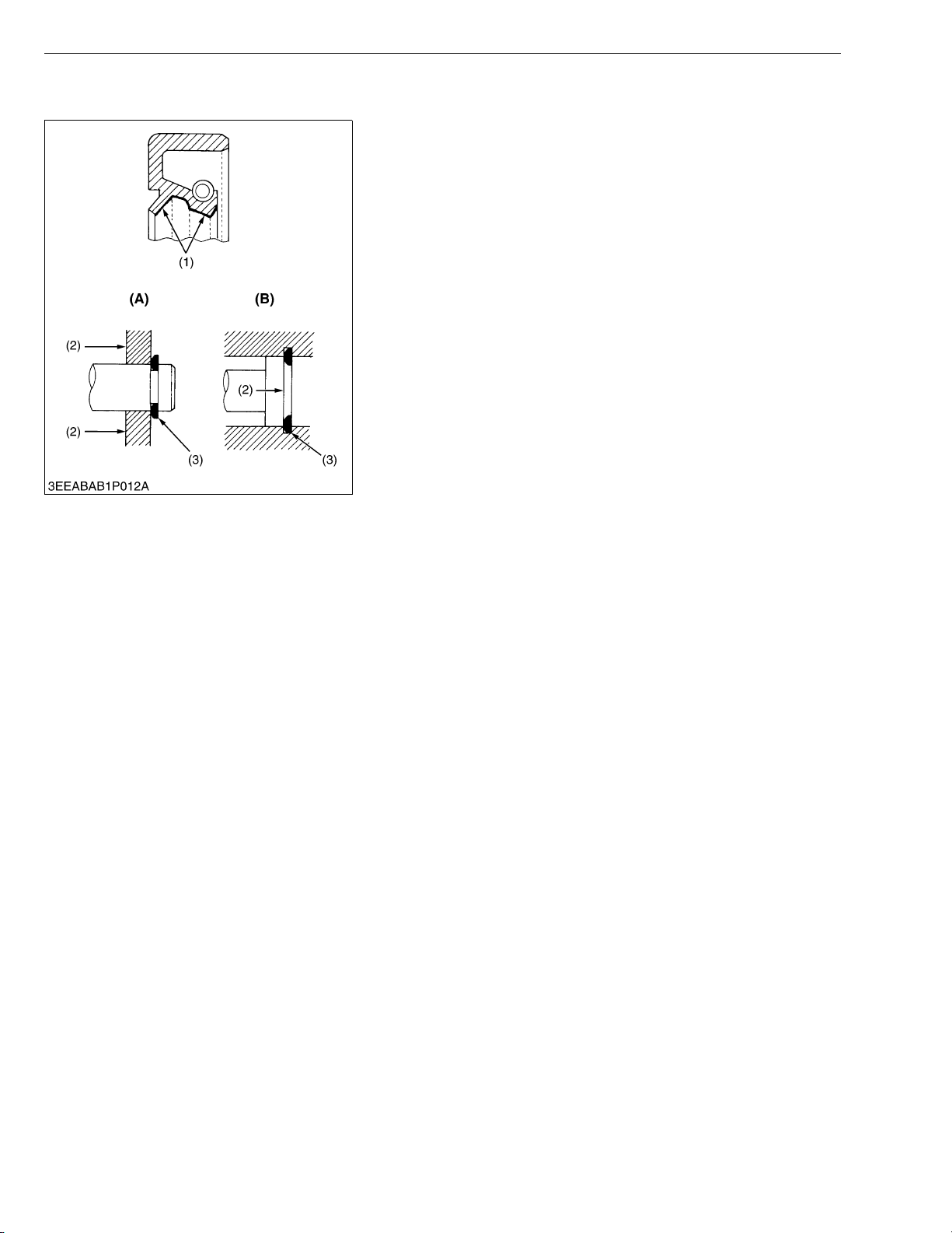
• When reassembling external or internal snap rings, position them
so that the sharp edge faces against the direction from which
force is applied.
• Be sure to perform run-in the serviced or reassembled engine.
Do not attempt to give heavy load at once, or serious damage
may result to the engine.
(1) Grease
(2) Force
(3) Place the Sharp Edge against the
Direction of Force
G GENERAL
(A) External Snap Ring
(B) Internal Snap Ring
W1011734
G-4
Page 15
V3307-DI-T-E2B, WSM
KiSC issued 01, 2009 A
G GENERAL
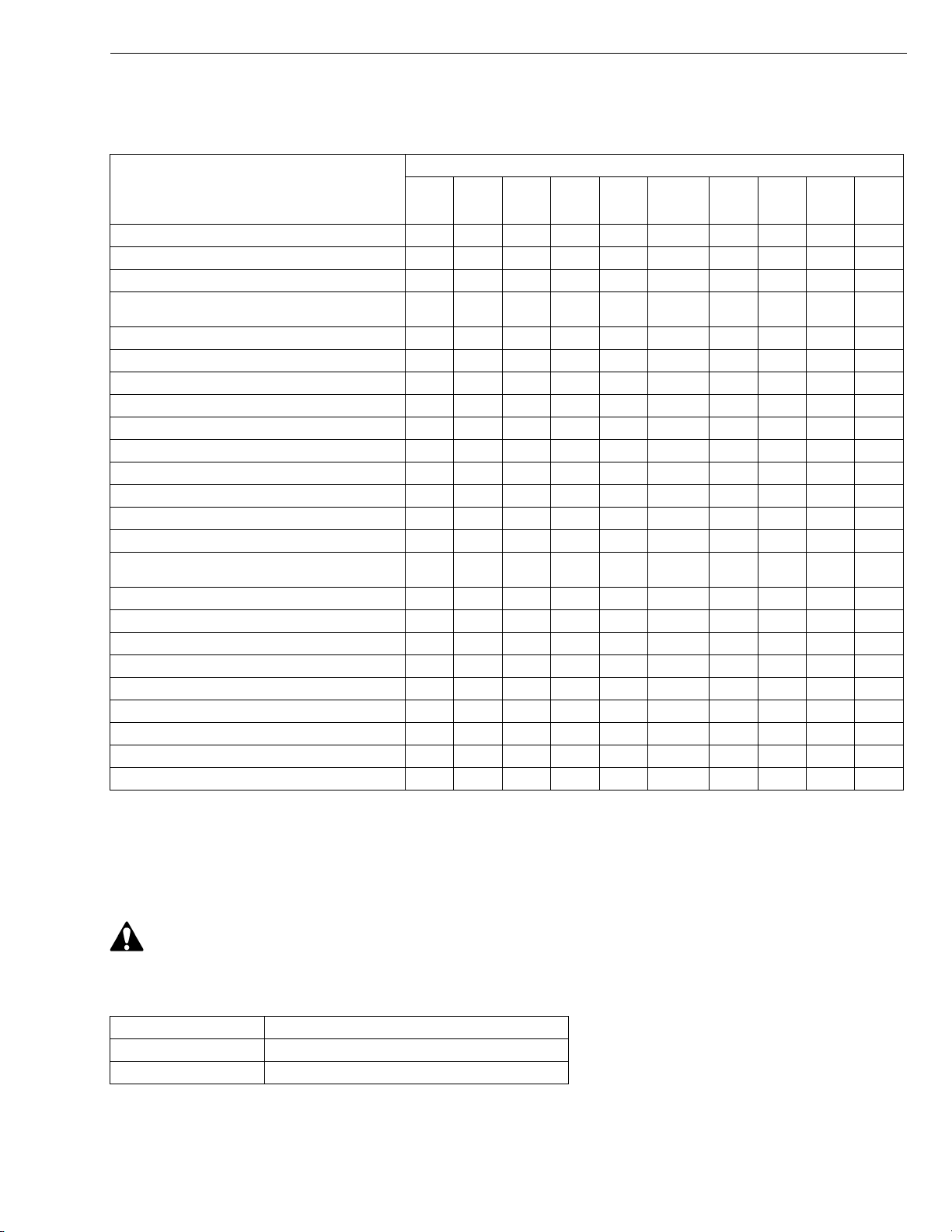
3. MAINTENANCE CHECK LIST
To maintain long-lasting and safe engine performance, make it a rule to carry out regular inspections by following
the table below.
Service Interval
1500
hrs
,
Every
3000
hrs
Every
1 year
Every
250
hrs
,
Every
Item
Changing engine oil ,, ,
Replacing oil filter cartridge ,,
*Checking fuel hoses and clamp bands ,
*Cleaning air cleaner element
(Replace the element after 6 times cleanings)
Cleaning fuel filter (Element type) ,
Checking battery electrolyte level ,
Checking radiator hoses and clamp bands ,
*Checking intake air line ,
Checking fan belt tension and damage ,,
*Replacing fuel filter cartridge ,
Replacing fan belt ,
Cleaning radiator interior ,
Checking valve clearance ,
Recharging battery ,
*Checking injection nozzle condition
(spraying, pressure and valve seat tightness)
*Checking turbocharger ,
*Checking fuel injection pump ,
*Checking injection timing (spill timing) ,
*Replacing air cleaner element ,
Changing radiator coolant (L.L.C.) ,
Replacing radiator hoses and clamp bands ,
*Replacing fuel hoses and clamp bands ,
*Replacing intake air line ,
Replacing battery ,
Initial
50 hrs
Every
50 hrs
Every
500
hrs
Every
1000
hrs
Every 1
or 2
months
• When the battery is used for less than 100 hours in a year, check its electrolyte yearly. (for refillable battery’s only)
• The items listed above (* marked) are registered as emission related critical parts by KUBOTA in the U.S.EPA
nonroad emission regulation.
As the engine owner, you are responsible for the performance of the required maintenance on the engine
according to the above instruction.
Every
2
years
W1029462
• When changing or inspecting, be sure to level and stop the engine.
Q NOTE
Changing interval of engine oil :
API service classification : above CD grade
Ambient temperature : below 35 °C (95 °F)
CAUTION
Model Interval
V3307-DI-T-E2B 500 Hrs or 1 year whichever comes first
Initial 50 Hrs
G-5
Page 16
V3307-DI-T-E2B, WSM
KiSC issued 01, 2009 A
G GENERAL
Q NOTE
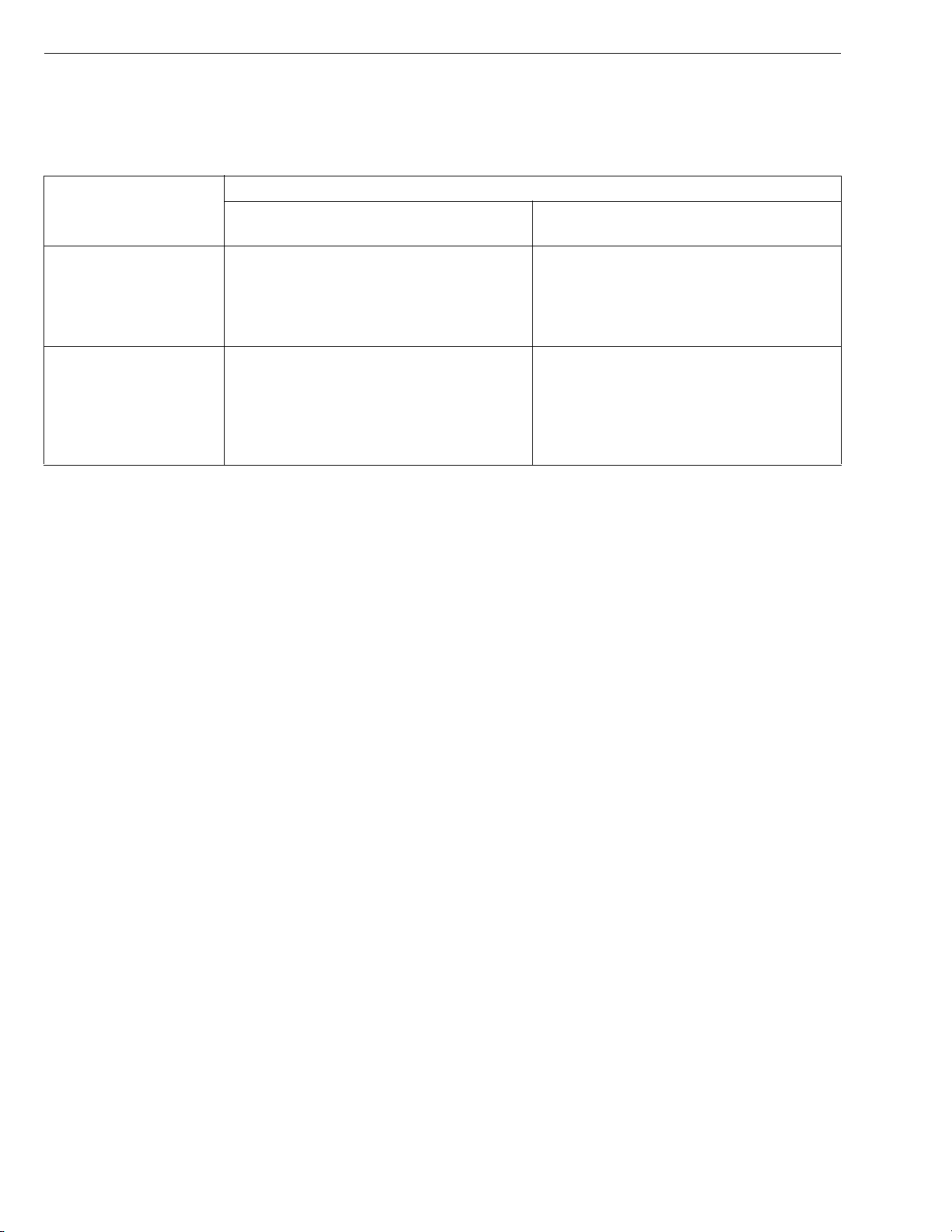
Engine Oil :
• Refer to the following table for the suitable American Petroleum Institute (API) classification of engine oil
according to the engine type (with internal EGR, external EGR or non-EGR) and the Fuel Type Used :
(Low Sulfur, Ultra Low Sulfur or High Sulfur Fuels).
Engine oil classification (API classification)
Fuel Type
High Sulfur Fuel
[0.05 % (500 ppm) ≤
Sulfur Content <
0.50 % (5000 ppm)]
Engines with non-EGR
Engines with internal EGR
CF
(If the "CF-4, CG-4, CH-4, or CI-4" engine
oil is used with a high-sulfur fuel, change
the engine oil at shorter intervals.
(approximately half))
Engines with external EGR
–
Low Sulfur Fuel
[Sulfur Content <
0.05 % (500 ppm)] or
Ultra Low Sulfur Fuel
[Sulfur Content <
CF, CF-4, CG-4, CH-4 or CI-4
CF or CI-4
(Class CF-4, CG-4 and CH-4 engine oils
cannot be used on EGR type engines.)
0.0015 % (15 ppm)]
EGR : Exhaust Gas Re-circulation
W1024941
• CJ-4 classification oil is intended for use in engines equipped with DPF (Diesel Particulate Filter) and is
Not Recommended for use in Kubota E2 specification engines.
• Oil used in the engine should have API classification and Proper SAE Engine Oil Viscosity according to
the ambient temperatures where the engine is operated.
• With strict emission control regulations now in effect, the CF-4 and CG-4 engine oils have been developed
for use with low sulfur fuels, for On-Highway vehicle engines. When a Non-Road engine runs on high
sulfur fuel, it is advisable to use a "CF or better" classification engine oil with a high Total Base Number
(a minimum TBN of 10 is recommended).
Fuel :
• Cetane Rating : The minimum recommended Fuel Cetane Rating is 45. A cetane rating greater than 50 is
preferred, especially for ambient temperatures below −20 °C (−4 °F) or elevations above 1500 m (5000 ft).
• Diesel Fuel Specification Type and Sulfur Content % (ppm) used, must be compliant with all applicable
emission regulations for the area in which the engine is operated.
• Use of diesel fuel with sulfur content less than 0.10 % (1000 ppm) is strongly recommended.
• If high-sulfur fuel (sulfur content 0.50 % (5000 ppm) to 1.0 % (10000 ppm)) is used as a diesel fuel, change
the engine oil and oil filter at shorter intervals. (approximately half)
• DO NOT USE Fuels that have sulfur content greater than 1.0 % (10000 ppm).
• Diesel fuels specified to EN 590 or ASTM D975 are recommended.
• No.2-D is a distillate fuel of lower volatility for engines in industrial and heavy mobile service. (SAE J313
JUN87)
• Since KUBOTA diesel engines of less than 56 kW (75 hp) utilize EPA Tier 4 and Interim Tier 4 standards,
the use of low sulfur fuel or ultra low sulfur fuel is mandatory for these engines, when operated in US EPA
regulated areas. Therefore, please use No.2-D S500 or S15 diesel fuel as an alternative to No.2-D, and use
No.1-D S500 or S15 diesel fuel as an alternative to No.1-D for ambient temperatures below −10 °C (14 °F).
1) SAE : Society of Automotive Engineers
2) EN : European Norm
3) ASTM : American Society of Testing and Materials
4) US EPA : United States Environmental Protection Agency
5) No.1-D or No.2-D, S500 : Low Sulfur Diesel (LSD) less than 500 ppm or 0.05 wt.%
No.1-D or No.2-D, S15 : Ultra Low Sulfur Diesel (ULSD) 15 ppm or 0.0015 wt.%
G-6
Page 17
V3307-DI-T-E2B, WSM
KiSC issued 01, 2009 A
4. CHECK AND MAINTENANCE
[1] DAILY CHECK POINTS
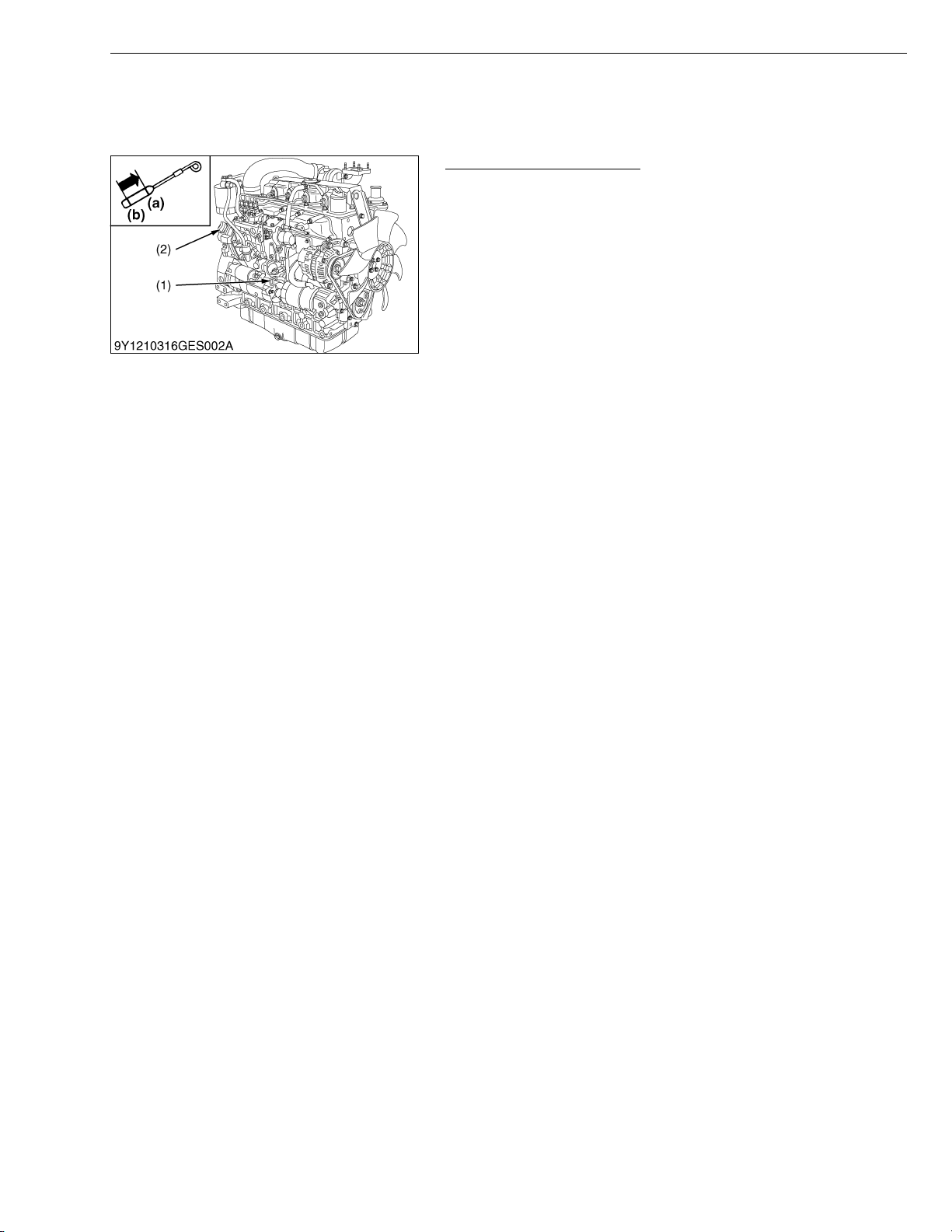
Checking Engine Oil Level
1. Level the engine.
2. To check the oil level, draw out the dipstick (1), wipe it clean,
reinsert it, and draw it out again.
Check to see that the oil level lies between the two notches.
3. If the level is too low, add new oil to the specified level.
IMPORTANTQ
• When using an oil of different maker or viscosity from the
previous one, drain old oil. Never mix two different types of
oil.
NOTEQ
• Be sure to inspect the engine, locating it on a horizontal
place. If placed on gradients, accurately, oil quantity may
not be measured.
• Be sure to keep the oil level between upper and lower lines
of the dipstick (1). Too much oil may cause a drop in output
or excessive blow-by gas. On the closed breather type
engine in which mist is sucked through port, too much oil
may caused oil hammer. While too little oil, may seize the
engine’s rotating and sliding parts.
(1) Dipstick
(2) Oil Filler Plug
G GENERAL
(a) Upper Line
(b) Lower Line
W1035676
G-7
Page 18
V3307-DI-T-E2B, WSM
KiSC issued 01, 2009 A
G GENERAL
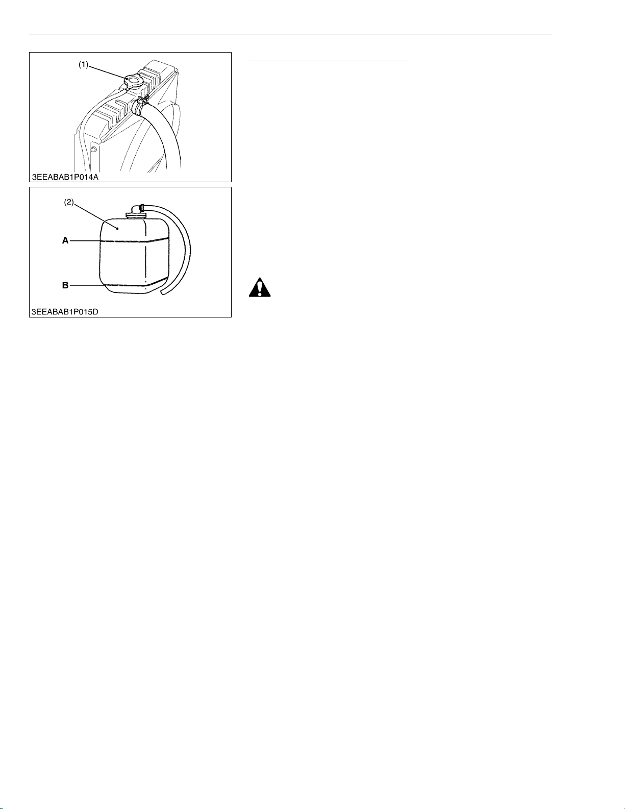
Checking and Replenish Coolant
1. Without recovery tank (2) :
Remove the radiator cap (1) and check to see that the coolant
level is just below the port.
With recovery tank (2) :
Check to see that the coolant level lies between FULL (A) and
LOW (B).
2. If coolant level is too low, check the reason for decreasing
coolant.
(Case 1)
If coolant is decreasing by evaporation, replenish only fresh, soft
water.
(Case 2)
If coolant is decreasing by leak, replenish coolant of the same
manufacture and type in the specified mixture ratio (fresh, soft
water and L.L.C.). If the coolant brand cannot be identified, drain
out all of the remaining coolant and refill with a totally new brand
of coolant mix.
CAUTION
• Do not remove the radiator cap (1) until coolant temperature
is below its boiling point. Then loosen the cap slightly to
relieve any excess pressure before removing the cap
completely.
IMPORTANTQ
• During filling the coolant, air must be vented from the engine
coolant passages. The air vents by jiggling the radiator
upper and lower hoses.
• Be sure to close the radiator cap (1) securely. If the cap is
loose or improperly closed, coolant may leak out and the
engine could overheat.
• Do not use an antifreeze and scale inhibitor at the same time.
• Never mix the different type or brand of L.L.C..
(1) Radiator Cap
(2) Recovery Tank
A : FULL
B : LOW
W1035779
G-8
Page 19
V3307-DI-T-E2B, WSM
KiSC issued 01, 2009 A
[2] CHECK POINTS OF INITIAL 50 HOURS
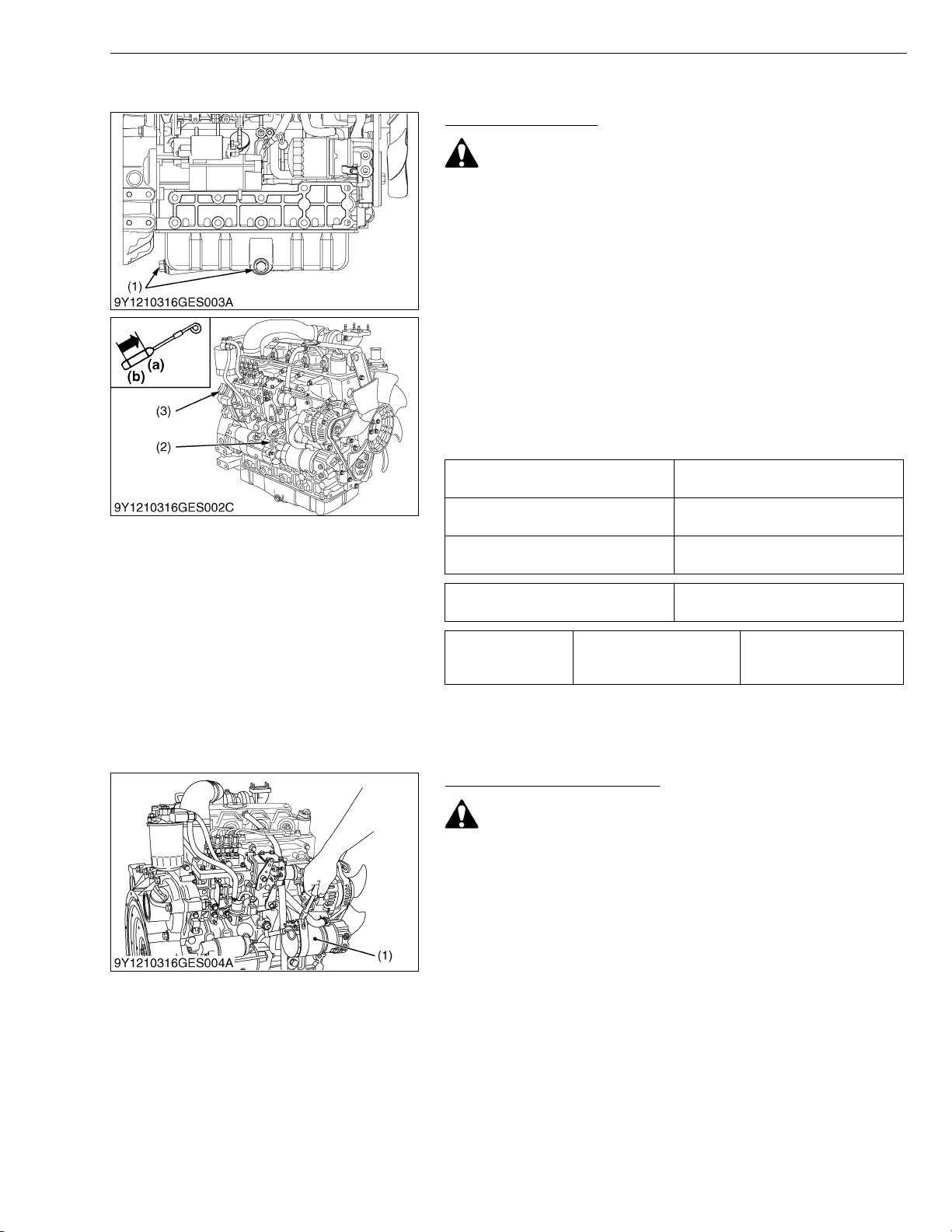
Changing Engine Oil
CAUTION
• Be sure to stop engine before changing engine oil.
1. Start and warm up the engine for approx. 5 minutes.
2. Place an oil pan underneath the engine.
3. To drain the used oil, remove the drain plug (1) at the bottom of
the engine and drain the oil completely.
4. Screw the drain plug (1).
5. Fill new oil up to upper line on the dipstick (2).
IMPORTANTQ
• When using an oil of different maker or viscosity from the
previous one, remove all of the old oil.
• Never mix two different types of oil.
• Engine oil should have properties of API classification CD/
CE/CF (See page G-6).
• Use the proper SAE Engine Oil according to ambient
temperature.
Above 25 °C (77 °F)
0 °C to 25 °C (32 °F to 77 °F)
Below 0 °C (32 °F)
G GENERAL
SAE 30 or SAE 10W-30
SAE 15W-40
SAE 20 or SAE 10W-30
SAE 15W-40
SAE 10W or SAE 10W-30
SAE 15W-40
Engine oil capacity
Tightening torque Drain plug
(1) Drain Plug
(2) Dipstick
(3) Oil Filler Plug
11.2 L
2.96 U.S.gals
45 to 53 N·m
4.5 to 5.5 kgf·m
33 to 39 lbf·ft
(a) Upper Line
(b) Lower Line
W1016604
Replacing Oil Filter Cartridge
CAUTION
• Be sure to stop the engine before changing filter cartridge.
1. Remove the oil filter cartridge (1) with the filter wrench.
2. Apply a slight coat of oil onto the new cartridge gasket.
3. To install the new cartridge, screw it in by hand. Over tightening
may cause deformation of rubber gasket.
4. After the new cartridge has been replaced, the engine oil
normally decrease a little. Thus see that the engine oil does not
leak through the seal and be sure to read the oil level on the
dipstick. Then, replenish the engine oil up to the specified level.
IMPORTANTQ
• To prevent serious damage to the engine, replacement
element must be highly efficient. Use only a KUBOTA
genuine filter or its equivalent.
(1) Engine Oil Filter Cartridge
W1017137
G-9
Page 20
V3307-DI-T-E2B, WSM
KiSC issued 01, 2009 A
G GENERAL
Checking Fan Belt Tension
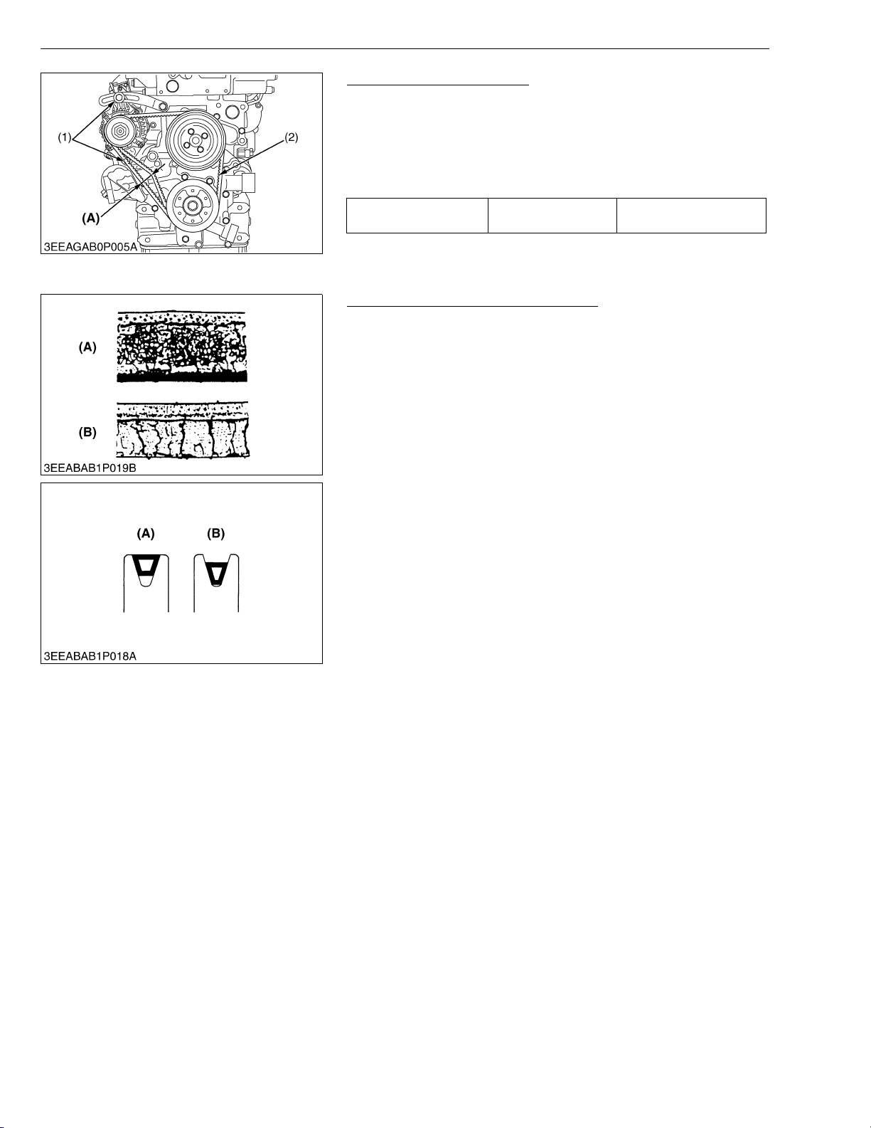
1. Measure the deflection (A), depressing the fan belt (2) halfway
between the fan drive pulley and alternator pulley at specified
force 98 N (10 kgf, 22 lbf).
2. If the measurement is not within the factory specifications, loosen
the alternator mounting screws (1) and relocate the alternator to
adjust.
Deflection (A) Factory spec.
10.0 to 12.0 mm
0.394 to 0.472 in.
(1) Alternator Mounting Screw
(2) Fan Belt
(A) Deflection
W1208957
Checking Fan Belt Damage and Wear
1. Check the fan belt for damage.
2. If the fan belt is damaged, replace it.
3. Check if the fan belt is worn and sunk in the pulley groove.
4. If the fan belt is nearly worn out and deeply sunk in the pulley
groove, replace it.
(A) Good (B) Bad
W1033474
G-10
Page 21
V3307-DI-T-E2B, WSM
KiSC issued 01, 2009 A
[3] CHECK POINT OF EVERY 50 HOURS
Checking Fuel Hoses and Clamp Bands
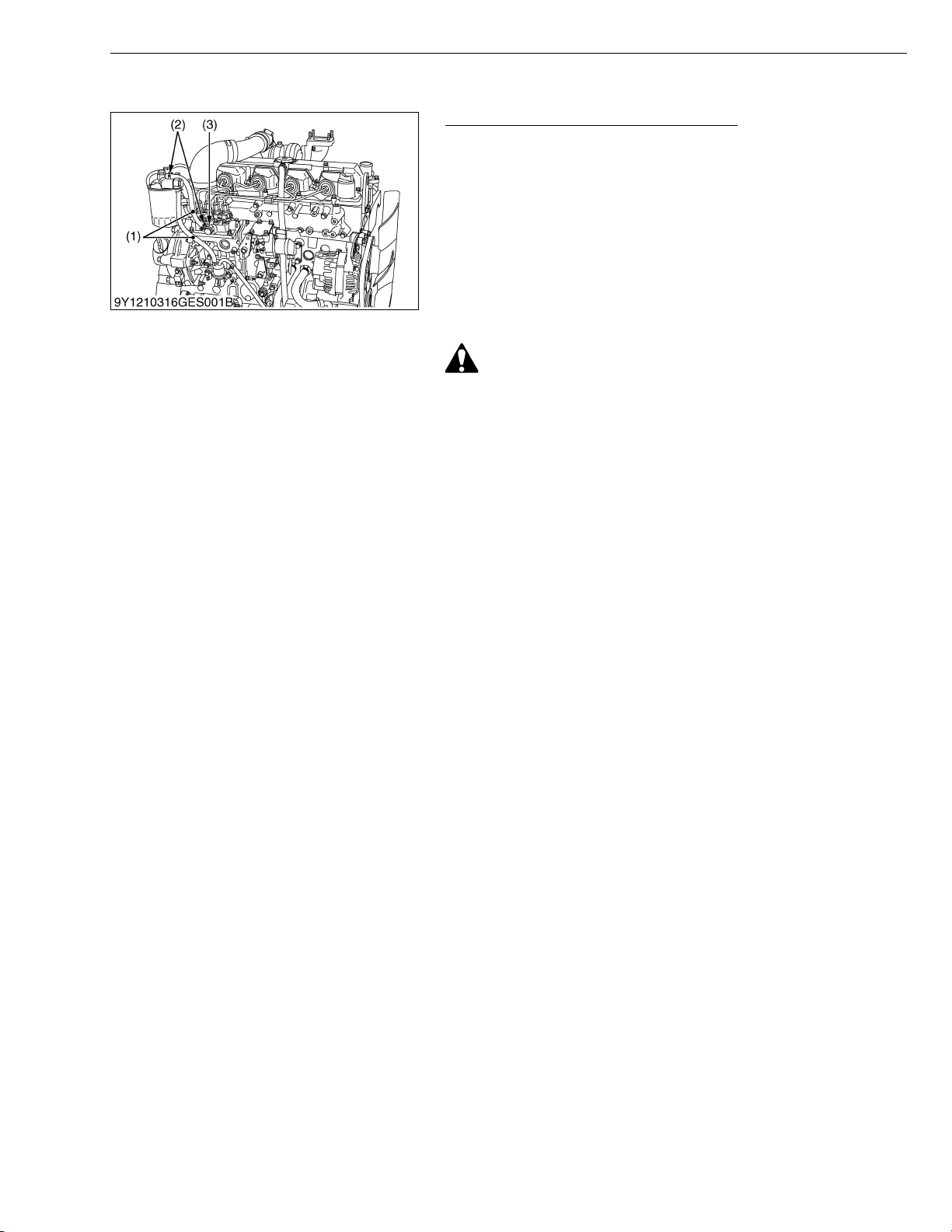
1. If the clamp band (2) is loose, apply oil to the threads and
securely retighten it.
2. The fuel hose (1) is made of rubber and ages regardless of the
period service.
Change the fuel pipe together with the clamp band (2) every two
years.
3. However, if the fuel hose (1) and clamp bands (2) are found to be
damaged or deteriorate earlier than two years, then change or
remedy.
4. After the fuel hose (1) and the clamp bands (2) have been
changed, bleed the fuel system.
CAUTION
• Stop the engine when attempting the check and change
prescribed above.
(When bleeding fuel system)
1. Fill the tank with fuel and open the cock.
2. Loosen the air vent coupling bolt of fuel filter a few turns.
3. When there is no more air bubbles in the fuel coming out of this
coupling bolt, tighten the coupling bolt.
4. Open the air vent cock (3) on the top of fuel injection pump.
5. If equipped electrical fuel feed pump, turn the key on AC position
and pump the fuel up for 10 to 15 seconds.
If equipped mechanical fuel feed pump, set the stop lever on stop
position and crank the engine for 10 to 15 seconds.
6. Close securely the air vent cock (3) after air bleeding.
IMPORTANTQ
• Except when venting the air, be sure to keep closed the air
vent coupling bolt of the fuel injection pump. Otherwise, the
engine may stall.
(1) Fuel Hose
(2) Clamp Band
G GENERAL
(3) Air Vent Cock
W1035921
G-11
Page 22
V3307-DI-T-E2B, WSM
KiSC issued 01, 2009 A
[4] CHECK POINTS OF EVERY 250 HOURS
Checking Fan Belt Tension
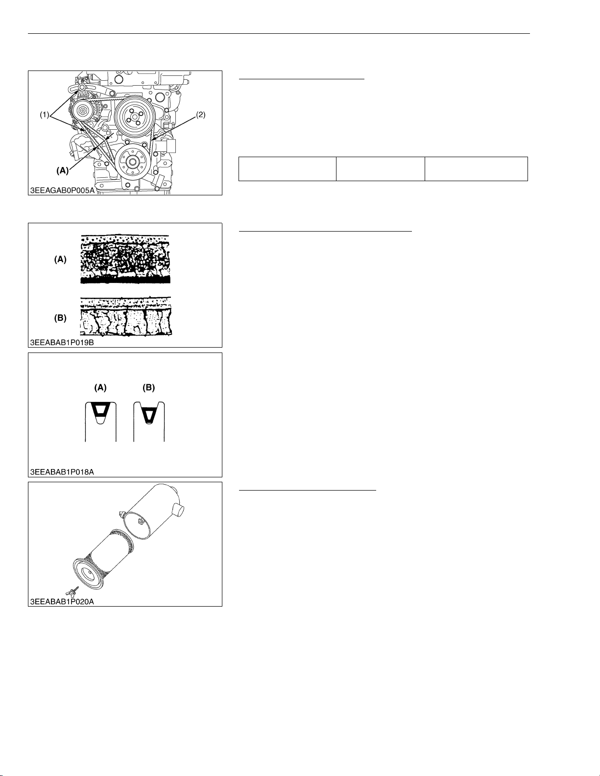
1. Measure the deflection (A), depressing the fan belt (2) halfway
between the fan drive pulley and alternator pulley at specified
force 98 N (10 kgf, 22 lbf).
2. If the measurement is not within the factory specifications, loosen
the alternator mounting screws (1) and relocate the alternator to
adjust.
Deflection (A) Factory spec.
G GENERAL
10.0 to 12.0 mm
0.394 to 0.472 in.
(1) Alternator Mounting Screw
(2) Fan Belt
(A) Deflection
W1014131
Checking Fan Belt Damage and Wear
1. Check the fan belt for damage.
2. If the fan belt is damaged, replace it.
3. Check if the fan belt is worn and sunk in the pulley groove.
4. If the fan belt is nearly worn out and deeply sunk in the pulley
groove, replace it.
(A) Good (B) Bad
W1209480
Cleaning Air Cleaner Element
1. Remove the air cleaner element.
2. Use clean dry compressed air on the inside of the element.
Pressure of compressed air must be under 205 kPa (2.1 kgf/cm
30 psi).
Maintain reasonable distance between the nozzle and the filter.
NOTEQ
• The air cleaner uses a dry element. Never apply oil to it.
• Do not run the engine with filter element removed.
• Change the element once a year or every 6th cleaning.
W1045746
G-12
2
,
Page 23
V3307-DI-T-E2B, WSM
KiSC issued 01, 2009 A
G GENERAL
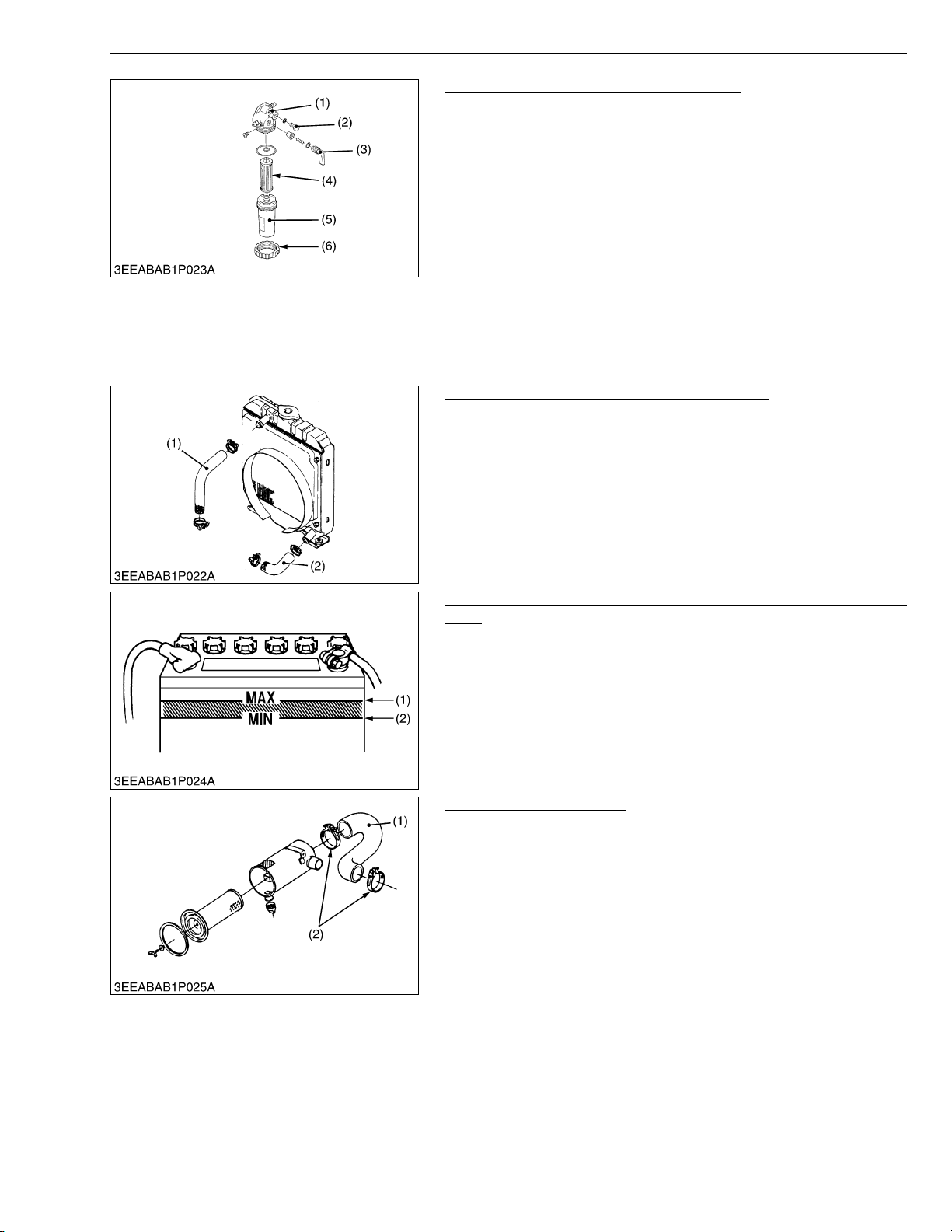
Cleaning Fuel Filter (Element Type only)
1. Close the fuel cock (3).
2. Unscrew the retaining ring (6) and remove the filter cup (5), and
rinse the inside with kerosene.
3. Take out the element (4) and dip it in the kerosene to rinse.
4. After cleaning, reassemble the fuel filter, keeping out dust and
dirt.
5. Bleed the fuel system.
IMPORTANTQ
• If dust and dirt enter the fuel, the fuel injection pump and
injection nozzle will wear quickly. To prevent this, be sure
to clean the filter cup (5) periodically.
(1) Cock Body
(2) Air Vent Plug
(3) Fuel Cock
(4) Filter Element
(5) Filter Cup
(6) Retaining Ring
W1046058
Checking Radiator Hoses and Clamp Bands
1. Check to see if the radiator hoses are properly fixed every 250
hours of operation or every six months, whichever comes first.
2. If the clamp band is loose, apply oil to the threads and retighten
it securely.
3. The water hose is made of rubber and tends to age. It must be
replaced every two years. Also replace the clamp band and
tighten it securely.
(1) Upper Hose (2) Lower Hose
W1029518
Checking Battery Electrolyte Level (for Refillable Battery’s
only)
1. Check the battery electrolyte level.
2. If the level is below than lower level line (2), and the distilled water
to pour level of each cell.
(1) Upper Level Line (2) Lower Level Line
W1047154
Checking Intake Air Line
1. Check to see if the intake air hose (1) is properly fixed every 250
hours of operation.
2. If the clamp bands (2) are loose, apply oil to the threads and
retighten them securely.
3. The intake air hose (1) is made of rubber and tends to age. It
must be change every two years. Also change the clamp bands
(2) and tighten them securely.
IMPORTANTQ
• To prevent serious damage to the engine, keep out any dust
inside the intake air line.
(1) Intake Air Hose (2) Clamp Band
W1029631
G-13
Page 24
V3307-DI-T-E2B, WSM
KiSC issued 01, 2009 A
[5] CHECK POINTS OF EVERY 500 HOURS
Changing Engine Oil
CAUTION
• Be sure to stop engine before changing engine oil.
1. Start and warm up the engine for approx. 5 minutes.
2. Place an oil pan underneath the engine.
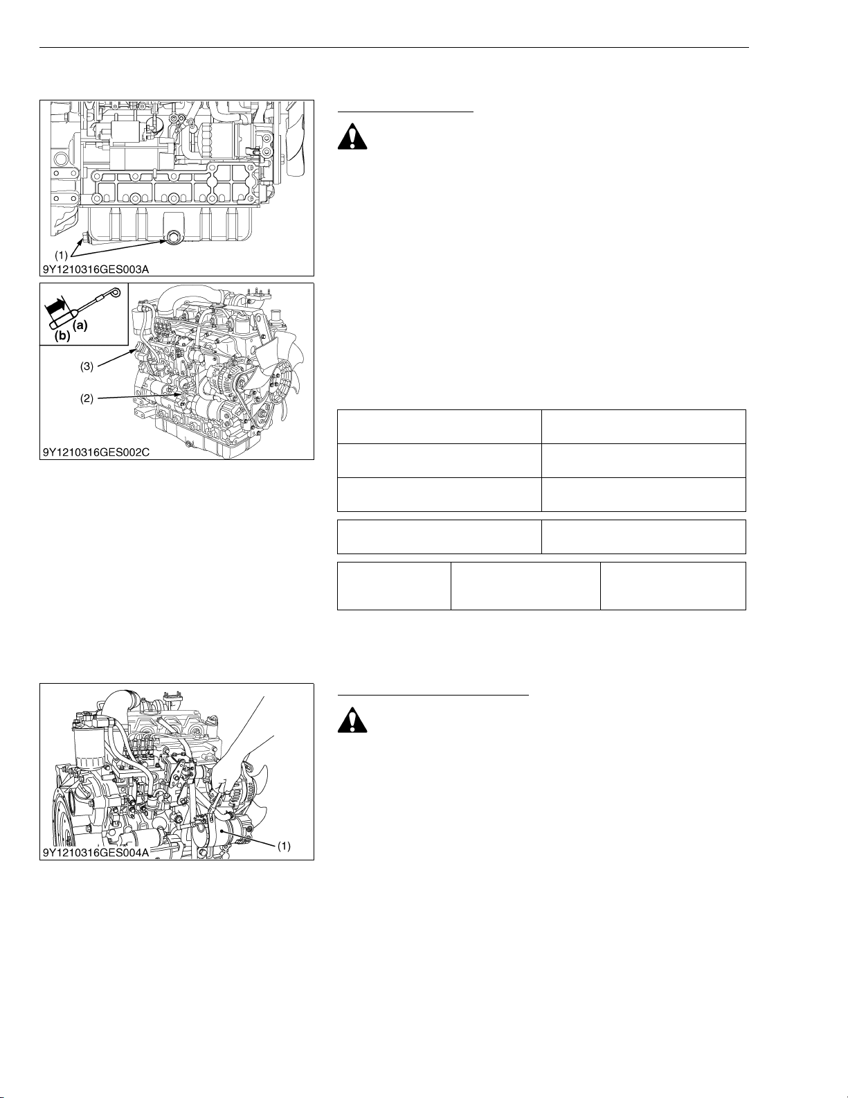
3. To drain the used oil, remove the drain plug (1) at the bottom of
the engine and drain the oil completely.
4. Screw the drain plug (1).
5. Fill new oil up to upper line on the dipstick (2).
IMPORTANTQ
• When using an oil of different maker or viscosity from the
previous one, remove all of the old oil.
• Never mix two different types of oil.
• Engine oil should have properties of API classification CD/
CE/CF (See page G-6).
• Use the proper SAE Engine Oil according to ambient
temperature.
Above 25 °C (77 °F)
0 °C to 25 °C (32 °F to 77 °F)
Below 0 °C (32 °F)
G GENERAL
SAE 30 or SAE 10W-30
SAE 15W-40
SAE 20 or SAE 10W-30
SAE 15W-40
SAE 10W or SAE 10W-30
SAE 15W-40
Engine oil capacity
Tightening torque Drain plug
(1) Drain Plug
(2) Dipstick
(3) Oil Filler Plug
11.2 L
2.96 U.S.gals
45 to 53 N·m
4.5 to 5.5 kgf·m
33 to 39 lbf·ft
(a) Upper Line
(b) Lower Line
W1014590
Replacing Oil Filter Cartridge
CAUTION
• Be sure to stop the engine before changing filter cartridge.
1. Remove the oil filter cartridge (1) with the filter wrench.
2. Apply a slight coat of oil onto the new cartridge gasket.
3. To install the new cartridge, screw it in by hand. Over tightening
may cause deformation of rubber gasket.
4. After the new cartridge has been replaced, the engine oil
normally decrease a little. Thus see that the engine oil does not
leak through the seal and be sure to read the oil level on the
dipstick. Then, replenish the engine oil up to the specified level.
IMPORTANTQ
• To prevent serious damage to the engine, replacement
element must be highly efficient. Use only a KUBOTA
genuine filter or its equivalent.
(1) Engine Oil Filter Cartridge
W1015117
G-14
Page 25
V3307-DI-T-E2B, WSM
KiSC issued 01, 2009 A
G GENERAL
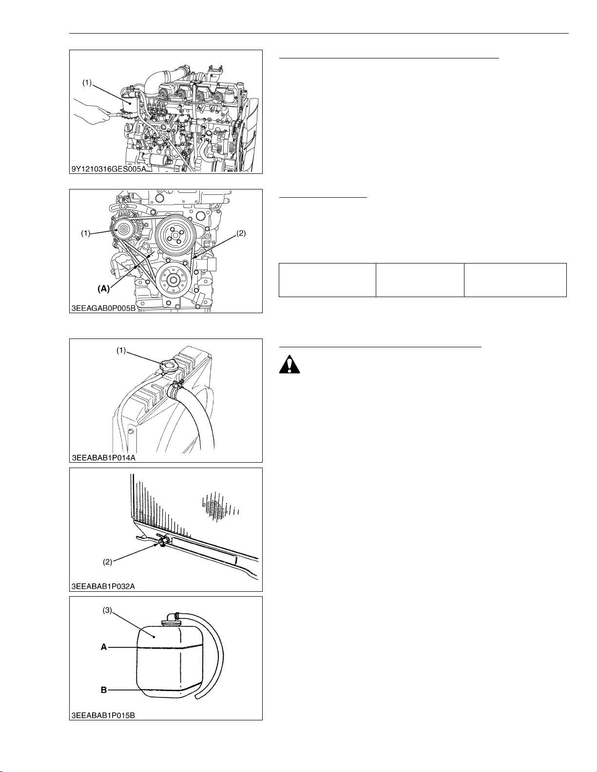
Replacing Fuel Filter Cartridge (Cartridge Type)
Water and dust in fuel are collected in the filter cartridge. So,
change the filter cartridge every 500 hours service.
1. Remove the used filter cartridge with filter wrench.
2. Apply a thin film of fuel to the surface of new filter cartridge gasket
before screwing on.
3. Then tighten enough by hand.
4. Loosen the air vent plug to let the air out.
5. Start engine and check for fuel leakage.
(1) Fuel Filter Cartridge
W1037062
Replacing Fan Belt
1. Remove the alternator (1).
2. Remove the fan belt (2).
3. Replace new fan belt.
4. Install the alternator.
5. Check the fan belt tension.
10.0 to 12.0 mm / 98 N
Deflection (A) Factory spec.
0.394 to 0.472 in. / 98 N
(10 kgf, 22 lbf)
(1) Alternator
(2) Fan Belt
(A) Deflection
W1052220
Cleaning Water Jacket and Radiator Interior
CAUTION
• Do not remove the radiator cap (1) when the engine is hot.
Then loosen cap slightly to the stop to relieve any excess
pressure before removing cap completely.
1. Stop the engine and let cool down.
2. To drain the coolant, open the radiator drain plug (2) and remove
the radiator cap (1). Then radiator cap (1) must be removed to
completely drain the coolant. And open the drain cock of engine
body.
3. After all coolant is drained, close the drain plug (2).
4. Fill with clean water and cooling system cleaner.
5. Follow directions of the cleaner instruction.
6. After flushing, fill with clean water and anti-freeze until the coolant
level is just below the port. Install the radiator cap (1) securely.
7. Fill with coolant up to “FULL” (A) mark on the recovery tank (3).
8. Start and operate the engine for few minutes.
9. Stop the engine and let cool. Check coolant level of radiator and
recovery tank (3) and add coolant if necessary.
IMPORTANTQ
• Do not start engine without coolant.
• Use clean, fresh, soft water and anti-freeze to fill the radiator
and recovery tank (3).
• When the anti-freeze is mixed with fresh, soft water, the antifreeze mixing ratio must be less than 50 %.
• Securely tighten radiator cap (1). If the cap is loose or
improperly fitted, water may leak out and the engine could
overheat.
(1) Radiator Cap
(2) Drain Plug
(3) Recovery Tank
A : Full
B : Low
W1038102
G-15
Page 26
V3307-DI-T-E2B, WSM
KiSC issued 01, 2009 A
G GENERAL
Anti-Freeze
• There are two types of anti-freeze available: use the permanent
type (PT) for this engine.
• Before adding anti-freeze for the first time, clean the radiator
interior by pouring fresh, soft water and draining it a few times.
• The procedure for mixing water and anti-freeze differs according
to the make of the anti-freeze and the ambient temperature.
Basically, it should be referred to SAE J1034 standard, more
specifically also to SAE J814c.
• Mix the anti-freeze with fresh, soft water, and then fill into the
radiator.
IMPORTANTQ
• When the anti-freeze is mixed with fresh, soft water, the antifreeze mixing ratio must be less than 50 %.
Vol %
anti-freeze
40 –24 –11 106 223
50 –37 –35 108 226
Freezing point Boiling point*
°C °F °C °F
* At 1.013 × 100000 Pa (760 mmHg) pressure (atmospheric). A
higher boiling point is obtained by using a radiator pressure cap
which permits the development of pressure within the cooling
system.
NOTEQ
• The above data represents industrial standards that
necessitate a minimum glycol content in the concentrated
anti-freeze.
• When the coolant level drops due to evaporation, add fresh,
soft water only to keep the anti-freeze mixing ratio less than
50 %. In case of leakage, add anti-freeze and fresh, soft
water in the specified mixing ratio.
• Anti-freeze absorbs moisture. Keep unused anti-freeze in a
tightly sealed container.
• Do not use radiator cleaning agents when anti-freeze has
been added to the coolant.
(Anti-freeze contains an anti-corrosive agent, which will
react with the radiator cleaning agent forming sludge which
will affect the engine parts.)
W1039218
G-16
Page 27
V3307-DI-T-E2B, WSM
KiSC issued 01, 2009 A
[6] CHECK POINT OF EVERY 1000 HOURS
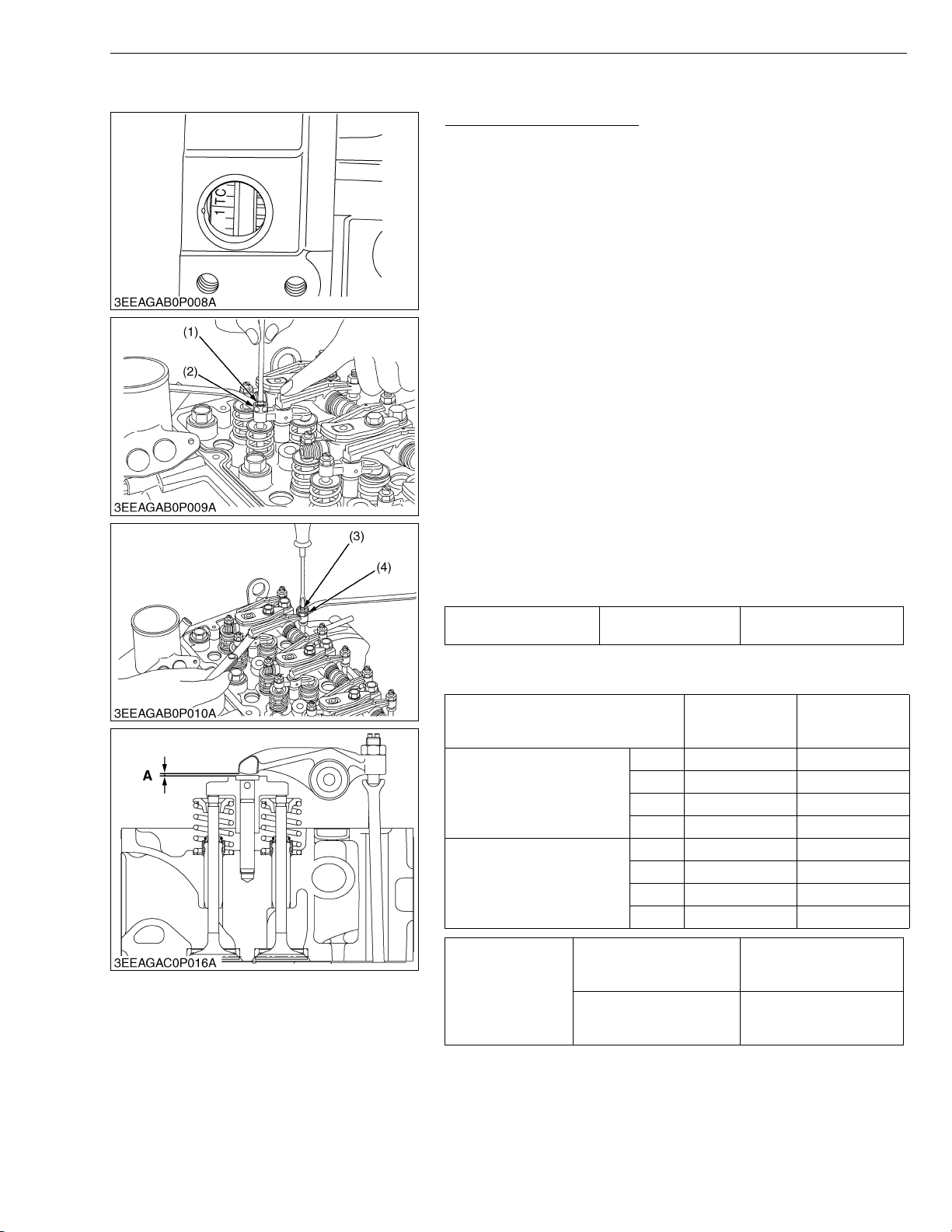
Checking Valve Clearance
IMPORTANTQ
• Valve clearance must be checked and adjusted when engine
is cold.
1. Remove the high pressure pipes, glow lead, glow plugs and the
cylinder head cover.
2. Align the 1TC mark of flywheel and the convex of flywheel
housing timing windows so that the first piston (front cover side)
comes to the compression top dead center.
[Adjustable type of valve bridge arm]
3. Before adjusting the valve clearance, adjust the valve bridge arm
evenly to the valve stem.
4. Loosen the lock nut (2) of adjusting screw (1) and adjust with
screw.
5. Slightly push the rocker arm with your fingers and screw in the
adjusting screw (1) slowly until you feel the screw touch the top
of valve stem, then tighten the lock nut (2).
6. Loosen the lock nut (4) of adjusting screw (3) (push rod side) and
insert the feeler gauge between the rocker arm and the head of
valve bridge arm. Set the adjusting screw (3) to the specified
value, then tighten the lock nut.
[Adjustment unnecessary type of valve bridge arm]
3. Loosen the lock nut (4) of adjusting screw (3) (push rod side) and
insert the feeler gauge between the rocker arm and the head of
valve bridge arm. Set the adjusting screw (3) to the specified
value, then tighten the lock nut.
Valve clearance (A) Factory spec.
G GENERAL
0.13 to 0.17 mm
0.0052 to 0.0066 in.
NOTEQ
• After adjusting, tighten the lock nut (4) securely.
Valve arrangement
Adjustment cylinder
Location of piston
When No.1 piston is at
compression top dead center
When No.1 piston is at
overlap position
Cylinder head cover screw
Tightening torque
Injection pipe retaining nut
(1) Adjusting Screw
(2) Lock Nut
(3) Adjusting Screw
(4) Lock Nut
1st ,,
2nd ,
3rd ,
4th
1st
2nd ,
3rd ,
4th ,,
A : Valve Clearance
IN. EX.
9.81 to 11.2 N·m
1.00 to 1.15 kgf·m
7.24 to 8.31 lbf·ft
23 to 36 N·m
2.3 to 3.7 kgf·m
17 to 26 lbf·ft
W1047000
G-17
Page 28
V3307-DI-T-E2B, WSM
KiSC issued 01, 2009 A
[7] CHECK POINTS OF EVERY 1 OR 2 MONTHS
Recharging
CAUTION
• When the battery is being activated, hydrogen and oxygen
gases in the battery are extremely explosive. Keep open
sparks and flames away from the battery at all times,
especially when charging the battery.
• When charging battery, remove battery vent plugs.
• When disconnecting the cable from the battery, start with
the negative terminal first. When connecting the cable to the
battery, start with the positive terminal first.
• Never check battery charge by placing a metal object across
the posts.
Use a voltmeter or hydrometer.
1) Slow Charging
1. Add distilled water if the electrolyte level is low. When charging,
the amount of electrolyte should be slightly lower than the
specified level to prevent overflow.
2. Connect the battery to the charging unit, following the
manufacture’s instructions.
3. As the electrolyte generates gas while charging, remove all port
caps.
4. The electrolyte temperature must not exceed 40 °C (104 °F)
during charging.
If it exceed 40 °C (104 °F), decrease the charging amperage or
stop charging for a while.
5. When charging several batteries in series, charge at the rate of
the smallest battery in the line.
2) Quick Charging
1. Determine the proper charging current and charging time with the
tester attached to the quick charger.
2. Determine the proper charging current as 1/1 of the battery
capacity. If the battery capacity exceeds 50 Ah, consider 50 A as
the maximum.
Q Precaution for Operating a Quick Charger
• Operate with a quick charger differs according to the type.
Consult the instruction manual and use accordingly.
G GENERAL
W1052658
G-18
Page 29
V3307-DI-T-E2B, WSM
KiSC issued 01, 2009 A
G GENERAL
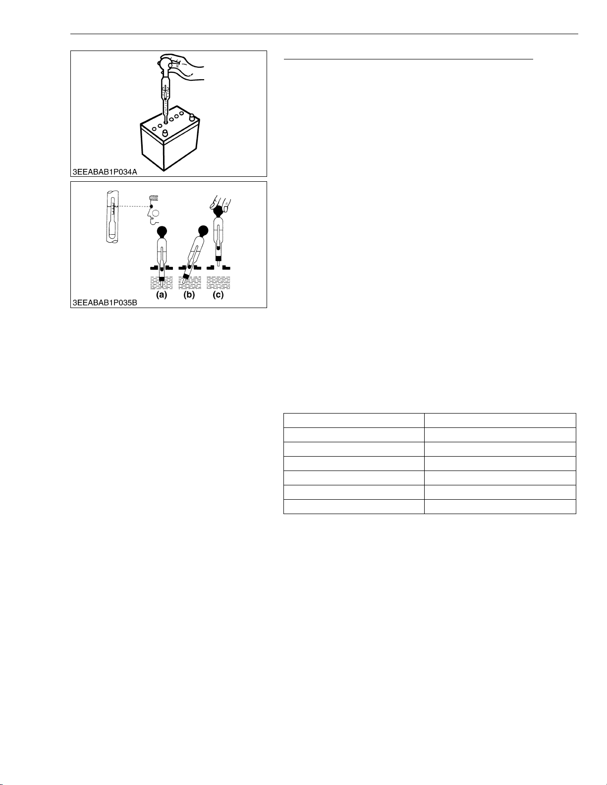
Battery Specific Gravity (for Refillable Battery’s only)
1. Check the specific gravity of the electrolyte in each cell with a
hydrometer.
2. When the electrolyte temperature differs from that at which the
hydrometer was calibrated, correct the specific gravity reading
following the formula mentioned in (Reference).
3. If the specific gravity is less than 1.215 (after it is corrected for
temperature), charge or replace the battery.
4. If the specific gravity differs between any two cells by more than
0.05, replace the battery.
NOTEQ
• Hold the hydrometer tube vertical without removing it from
the electrolyte.
• Do not suck too much electrolyte into the tube.
• Allow the float to move freely and hold the hydrometer at eye
level.
• The hydrometer reading must be taken at the highest
electrolyte level.
(Reference)
• Specific gravity slightly varies with temperature. To be exact, the
specific gravity decreases by 0.0007 with an increase of 1 °C
(0.0004 with an increase of 1 °F) in temperature, and increases
by 0.0007 with a decreases of 1 °C (0.0004 with a decrease of 1
°F).
Therefore, using 20 °C (68 °F) as a reference, the specific gravity
reading must be corrected by the following formula :
- Specific gravity at 20 °C = Measured value + 0.0007 ×
(electrolyte temperature : 20 °C)
- Specific gravity at 68 °F = Measured value + 0.0004 ×
(electrolyte temperature : 68 °F)
Specific Gravity State of Charge
1.260 Sp. Gr. 100 % Charged
1.230 Sp. Gr. 75 % Charged
1.200 Sp. Gr. 50 % Charged
1.170 Sp. Gr. 25 % Charged
1.140 Sp. Gr. Very Little Useful Capacity
1.110 Sp. Gr. Discharged
At an electrolyte temperature of 20 °C (68 °F)
(a) Good
(b) Bad
(c) Bad
W1012763
G-19
Page 30
V3307-DI-T-E2B, WSM
KiSC issued 01, 2009 A
G GENERAL
[8] CHECK POINTS OF EVERY 1500 HOURS
CAUTION
• Check the nozzle injection pressure and condition after confirming that there is nobody standing in the
direction the spray goes.
• If the spray from the nozzle directly contacts the human body, cells may be destroyed and blood poisoning
may be caused.
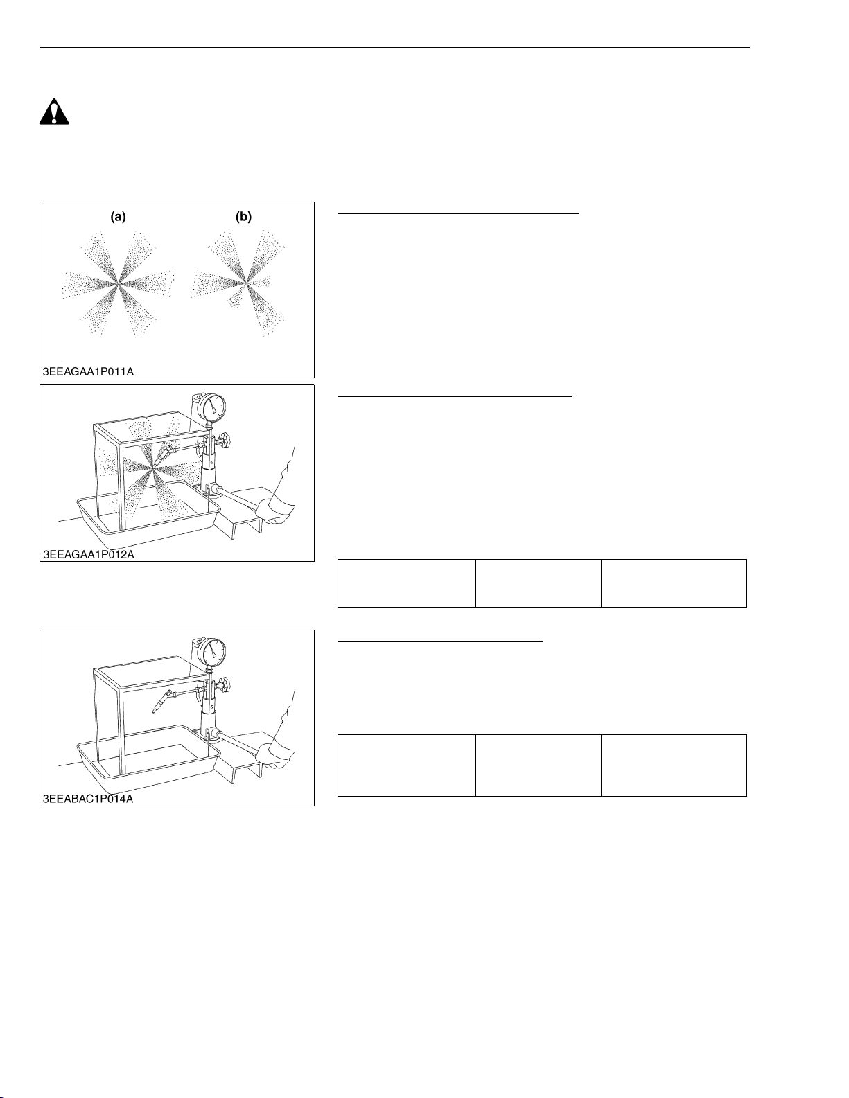
Checking Nozzle Spraying Condition
1. Attach the injection nozzle to the nozzle tester, and check the
nozzle spraying condition.
2. If the spraying condition is defective, replace the injection nozzle
assembly or repair at Kubota-authorized nozzle service shop.
(a) Good (b) Bad
W10371670
Checking Nozzle Injection Pressure
1. Attach the injection nozzle to the nozzle tester.
2. Slowly move the tester handle to measure the pressure at which
fuel begins jetting out from the nozzle.
3. If the measurement is not within the factory specifications,
replace the injection nozzle assembly or repair at Kubotaauthorized nozzle service shop.
NOTEQ
• Injection nozzle gasket must be replaced when the injection
nozzle is removed for checking.
Injection pressure
(1st stage)
Factory spec.
Checking Valve Seat Tightness
1. Attach the injection nozzle to the nozzle tester.
2. Raise the fuel pressure, and keep at 16.67 MPa (170.0 kgf/cm
2418 psi) for 10 seconds.
3. If any fuel leak is found, replace the injection nozzle assembly or
repair at Kubota-authorized nozzle service shop.
Valve seat tightness Factory spec.
18.64 to 19.61 MPa
190.0 to 200.0 kgf/cm
2703 to 2844 psi
W1037280
No fuel leak at
16.67 MPa
170.0 kgf/cm
2418 psi
2
W10374150
2
2
,
G-20
Page 31
V3307-DI-T-E2B, WSM
KiSC issued 01, 2009 A
[9] CHECK POINTS OF EVERY 3000 HOURS
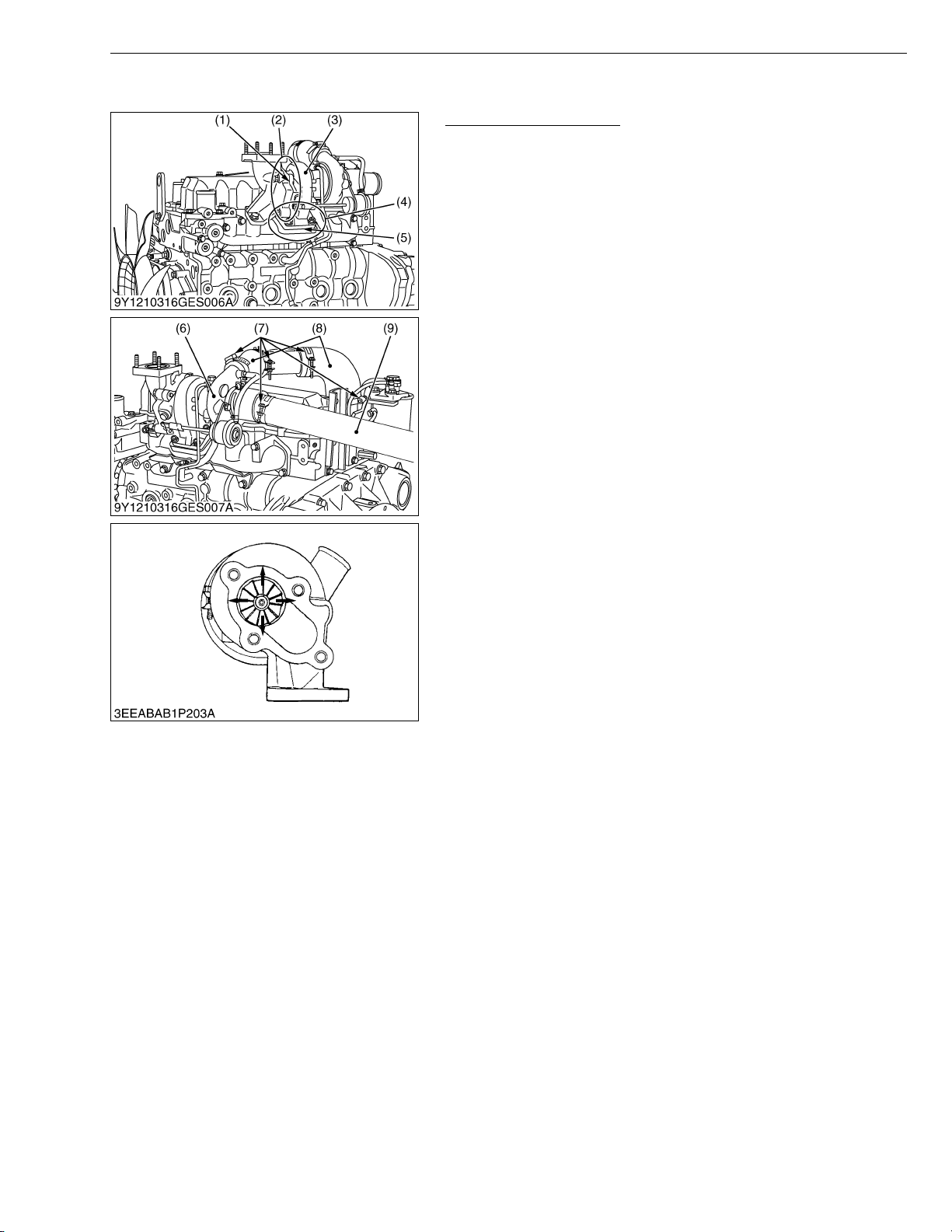
Checking Turbocharger
(Turbine Side)
1. Check the exhaust port (2) and inlet port (4) side of turbine
housing (3) to see if there is no exhaust gas leak.
2. If any gas leak is found, retighten the bolts and nuts or replace
the gasket ((1) or (5)) with new one.
(Compressor Side)
1. Check the inlet hose (9) of the compressor cover (6) to see if
there is no air leak.
2. If any air leak is found, change the clamp band (7) and / or inlet
hoses (9).
3. Check the intake hose (8) and the clamp band (7) to see if there
is not loose or crack.
4. If any loose or crack is found, tighten the clamp band (7) or
change the hose ((8) or (9)) to prevent dust from entry.
(Radial Clearance)
1. If the wheel contact to the housing, replace the turbocharger
assembly with new one.
(1) Gasket
(2) Exhaust Port
(3) Turbine Housing
(4) Inlet Port
(5) Gasket
G GENERAL
(6) Compressor Cover
(7) Clamp Band
(8) Intake Hose
(9) Inlet Hose
W1022082
G-21
Page 32
V3307-DI-T-E2B, WSM
KiSC issued 01, 2009 A
G GENERAL
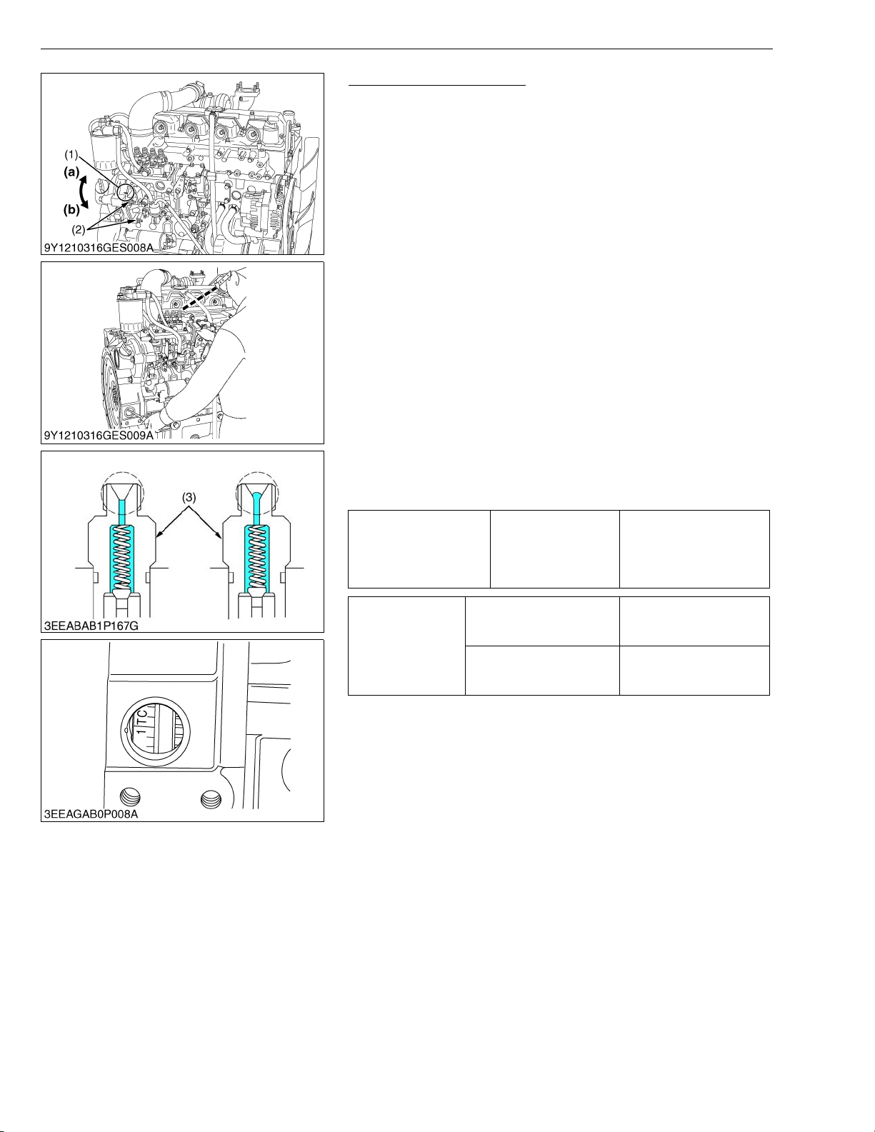
Checking Injection Timing
1. Make sure of matching the injection timing align mark (1) of the
injection pump unit and the flywheel housing, as shown in the
illustration.
2. Remove the injection pipes.
3. Remove the stop solenoid.
4. Turn the flywheel counterclockwise (viewed from flywheel side)
until the fuel fills up to the hole of the delivery valve holder (3) for
No.1 cylinder.
5. After the fuel fills up to the hole of the delivery valve holder (3) for
No.1 cylinder, turn back (clockwise) the flywheel around 1.6 rad
(90 °).
6. Turn the flywheel counterclockwise to set at around 0.17 rad
(10 °) before T.D.C..
7. Slowly turn the flywheel counterclockwise and stop turning when
the fuel begins to come up, to get the present injection timing.
8. Check to see the degree on flywheel.
The flywheel has mark “1TC” for the crank angle before the top
dead center of No.1 piston.
9. If the injection timing is not within the specification, rotate the
injection pump unit to adjust the injection timing.
IMPORTANTQ
• When installing the injection pump unit to the engine body,
follow the correct procedure.
See the “Injection Pump Unit”.
0.00436 rad before T.D.C.
to 0.0218 rad
Injection timing Factory spec.
after T.D.C.
(0.250 ° before T.D.C. to
1.25 ° after T.D.C.)
Injection pipe retaining nut
Tightening torque
Injection pump unit
mounting nut
(1) Injection Timing Align Mark
(2) Injection Pump Unit Mounting Nut
(3) Delivery Valve Holder
23 to 36 N·m
2.3 to 3.7 kgf·m
17 to 26 lbf·ft
18 to 20 N·m
1.8 to 2.1 kgf·m
13 to 15 lbf·ft
(a) Injection Timing Advanced
(b) Injection Timing Retarded
W1036105
G-22
Page 33
V3307-DI-T-E2B, WSM
KiSC issued 01, 2009 A
G GENERAL
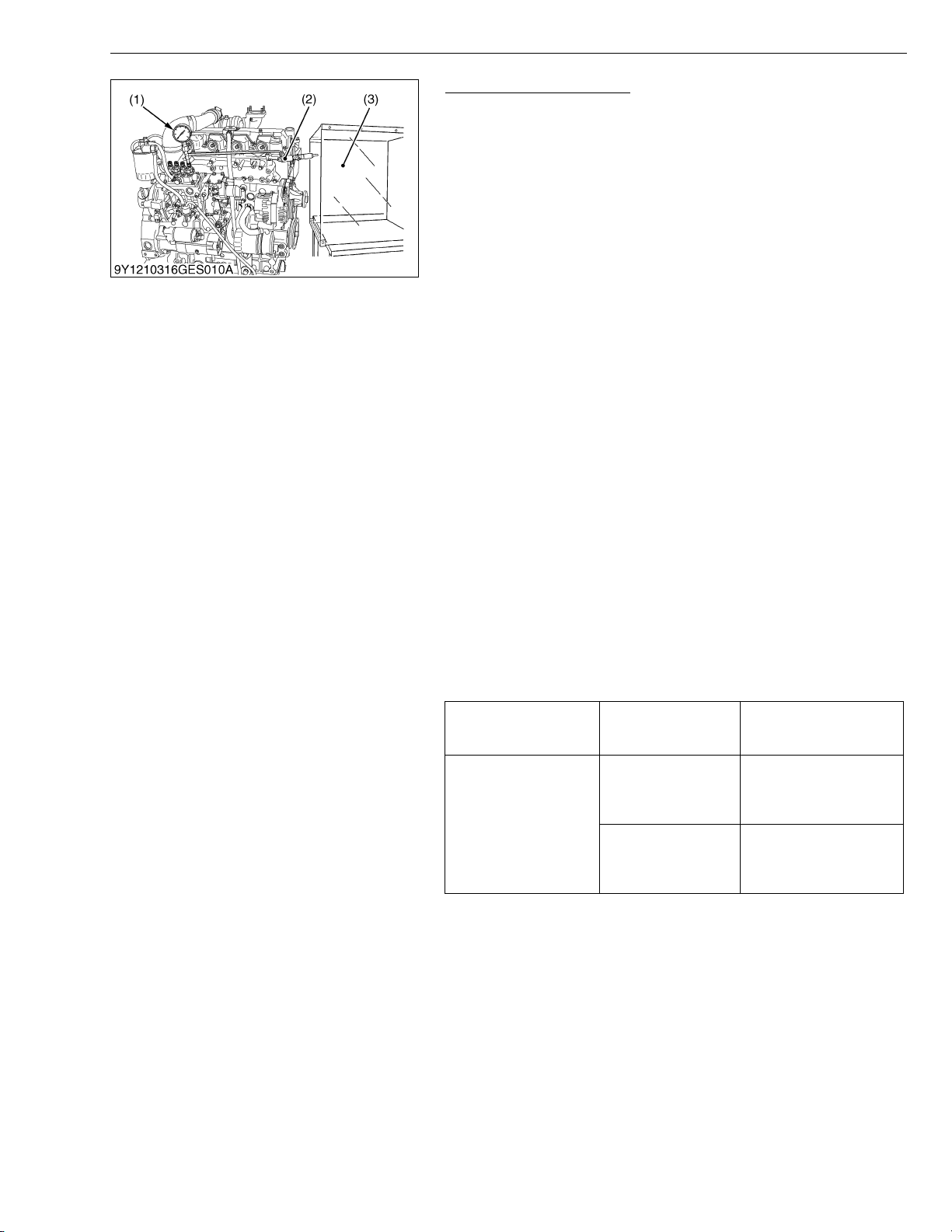
Checking Injection Pump
(Fuel Tightness of Pump Element)
1. Remove the engine stop solenoid.
2. Remove the injection pipes.
3. Install the injection pump pressure tester (1) to the injection
pump.
4. Install the injection nozzle (2) jetted with the proper injection
pressure to the injection pump pressure tester (1). (Refer to the
figure.)
5. Set the speed control lever to the maximum speed position.
6. Run the starter to increase the pressure.
7. If the pressure can not reach the allowable limit, replace the
pump with new one or repair with a Kubota-authorized pump
service shop.
(Fuel Tightness of Delivery Valve)
1. Remove the engine stop solenoid.
2. Remove the injection pipes.
3. Install a pressure tester to the fuel injection pump.
4. Install the injection nozzle (2) jetted with the proper injection
pressure to the injection pump pressure tester (1).
5. Run the starter to increase the pressure.
6. Stop the starter when the fuel jets from the injection nozzle (2).
After that, turn the flywheel by the hand and raise the pressure to
approx. 18.63 MPa (190.0 kgf/cm
2
, 2702 psi).
7. Now turn the flywheel back about half a turn (to keep the plunger
free). Maintain the flywheel at this position and clock the time
taken for the pressure to drop from 18.63 to 17.65 MPa (from
190.0 to 180.0 kgf/cm
8. Measure the time needed to decrease the pressure from 18.63 to
17.65 MPa (from 190.0 to 180.0 kgf/cm
2
, from 2702 to 2560 psi).
2
, from 2702 to 2560 psi).
9. If the measurement is less than allowable limit, replace the pump
with new one or repair with a Kubota-authorized pump service
shop.
Fuel tightness of pump
element
Fuel tightness of
delivery valve
Allowable limit
Factory spec.
Allowable limit
18.63 MPa
190.0 kgf/cm
2702 psi
10 seconds
18.63 → 17.65 MPa
190.0 → 180.0 kgf/cm
2702 → 2560 psi
5 seconds
18.63 → 17.65 MPa
190.0 → 180.0 kgf/cm
2702 → 2560 psi
2
2
2
NOTEQ
• Never try to disassemble the injection pump assembly. For
repairs, you are strongly requested to contact a Kubotaauthorized pump service shop.
(1) Injection Pump Pressure Tester
(2) Injection Nozzle
(3) Protection Cover for Jetted Fuel
W1022357
G-23
Page 34
V3307-DI-T-E2B, WSM
KiSC issued 01, 2009 A
[10] CHECK POINTS OF EVERY 1 YEAR
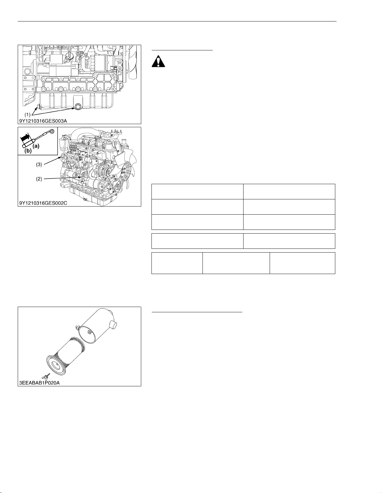
Changing Engine Oil
CAUTION
• Be sure to stop engine before changing engine oil.
1. Start and warm up the engine for approx. 5 minutes.
2. Place an oil pan underneath the engine.
3. To drain the used oil, remove the drain plug (1) at the bottom of
the engine and drain the oil completely.
4. Screw the drain plug (1).
5. Fill new oil up to upper line on the dipstick (2).
IMPORTANTQ
• When using an oil of different maker or viscosity from the
previous one, remove all of the old oil.
• Never mix two different types of oil.
• Engine oil should have properties of API classification CD/
CE/CF (See page G-6).
• Use the proper SAE Engine Oil according to ambient
temperature.
Above 25 °C (77 °F)
0 °C to 25 °C (32 °F to 77 °F)
Below 0 °C (32 °F)
G GENERAL
SAE 30 or SAE 10W-30
SAE 15W-40
SAE 20 or SAE 10W-30
SAE 15W-40
SAE 10W or SAE 10W-30
SAE 15W-40
Engine oil capacity
Tightening torque Drain plug
(1) Drain Plug
(2) Dipstick
(3) Oil Filler Plug
11.2 L
2.96 U.S.gals
45 to 53 N·m
4.5 to 5.5 kgf·m
33 to 39 lbf·ft
(a) Upper Line
(b) Lower Line
W1036031
Replacing Air Cleaner Element
1. Remove used air cleaner element.
2. Replace new air cleaner element.
NOTEQ
• The air cleaner uses a dry element. Never apply oil to it.
• Do not run the engine with filter element removed.
W1020554
G-24
Page 35
V3307-DI-T-E2B, WSM
KiSC issued 01, 2009 A
[11] CHECK POINTS OF EVERY 2 YEARS
Changing Radiator Coolant (L.L.C.)
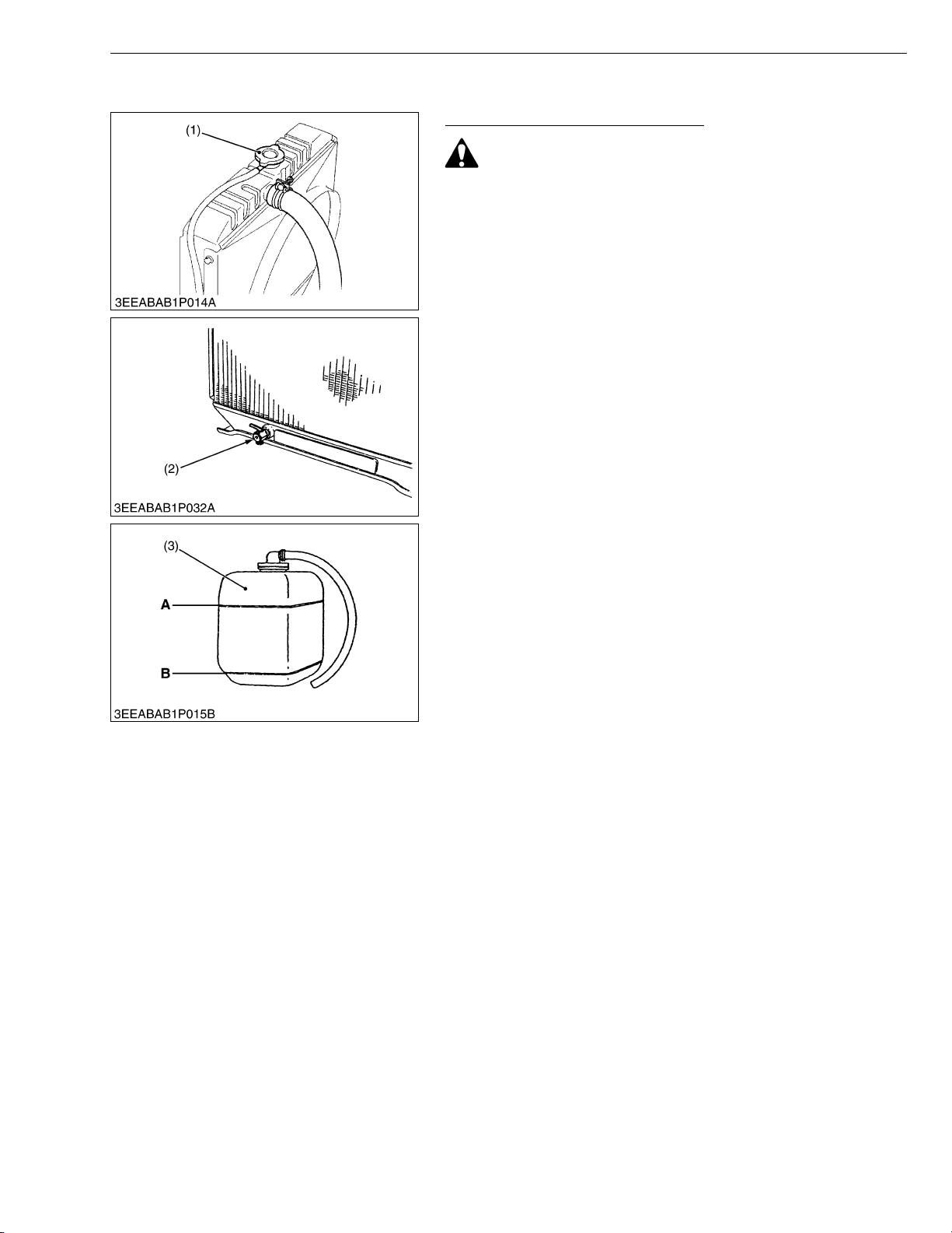
CAUTION
• Do not remove the radiator cap (1) when the engine is hot.
Then loosen cap slightly to the stop to relieve any excess
pressure before removing cap completely.
1. Stop the engine and let cool down.
2. To drain the coolant, open the radiator drain plug (2) and remove
the radiator cap (1). Then radiator cap (1) must be removed to
completely drain the coolant. And open the drain cock of engine
body.
3. After all coolant is drained, close the drain plug (2).
4. Fill with clean water and cooling system cleaner.
5. Follow directions of the cleaner instruction.
6. After flushing, fill with clean water and anti-freeze until the coolant
level is just below the port. Install the radiator cap (1) securely.
7. Fill with coolant up to “FULL” (A) mark on the recovery tank (3).
8. Start and operate the engine for few minutes.
9. Stop the engine and let cool. Check coolant level of radiator and
recovery tank (3) and add coolant if necessary.
IMPORTANTQ
• Do not start engine without coolant.
• Use clean, fresh, soft water and anti-freeze to fill the radiator
and recovery tank (3).
• When the anti-freeze is mixed with fresh, soft water, the antifreeze mixing ratio must be less than 50 %.
• Securely tighten radiator cap (1). If the cap is loose or
improperly fitted, water may leak out and the engine could
overheat.
(1) Radiator Cap
(2) Drain Plug
(3) Recovery Tank
G GENERAL
A : Full
B : Low
(To be continued)
W1024599
G-25
Page 36
V3307-DI-T-E2B, WSM
KiSC issued 01, 2009 A
G GENERAL
(Continued)
(Anti-freeze)
• There are two types of anti-freeze available: use the permanent
type (PT) for this engine.
• Before adding anti-freeze for the first time, clean the radiator
interior by pouring fresh, soft water and draining it a few times.
• The procedure for mixing water and anti-freeze differs according
to the make of the anti-freeze and the ambient temperature.
Basically, it should be referred to SAE J1034 standard, more
specifically also to SAE J814c.
• Mix the anti-freeze with fresh, soft water, and then fill into the
radiator.
IMPORTANTQ
• When the anti-freeze is mixed with fresh, soft water, the antifreeze mixing ratio must be less than 50 %.
Vol %
anti-freeze
40 –24 –11 106 223
50 –37 –35 108 226
Freezing point Boiling point*
°C °F °C °F
* At 1.013 × 100000 Pa (760 mmHg) pressure (atmospheric). A
higher boiling point is obtained by using a radiator pressure cap
which permits the development of pressure within the cooling
system.
NOTEQ
• The above data represents industrial standards that
necessitate a minimum glycol content in the concentrated
anti-freeze.
• When the coolant level drops due to evaporation, add fresh,
soft water only to keep the anti-freeze mixing ratio less than
50 %. In case of leakage, add anti-freeze and fresh, soft
water in the specified mixing ratio.
• Anti-freeze absorbs moisture. Keep unused anti-freeze in a
tightly sealed container.
• Do not use radiator cleaning agents when anti-freeze has
been added to the coolant.
(Anti-freeze contains an anti-corrosive agent, which will
react with the radiator cleaning agent forming sludge which
will affect the engine parts.)
W1024852
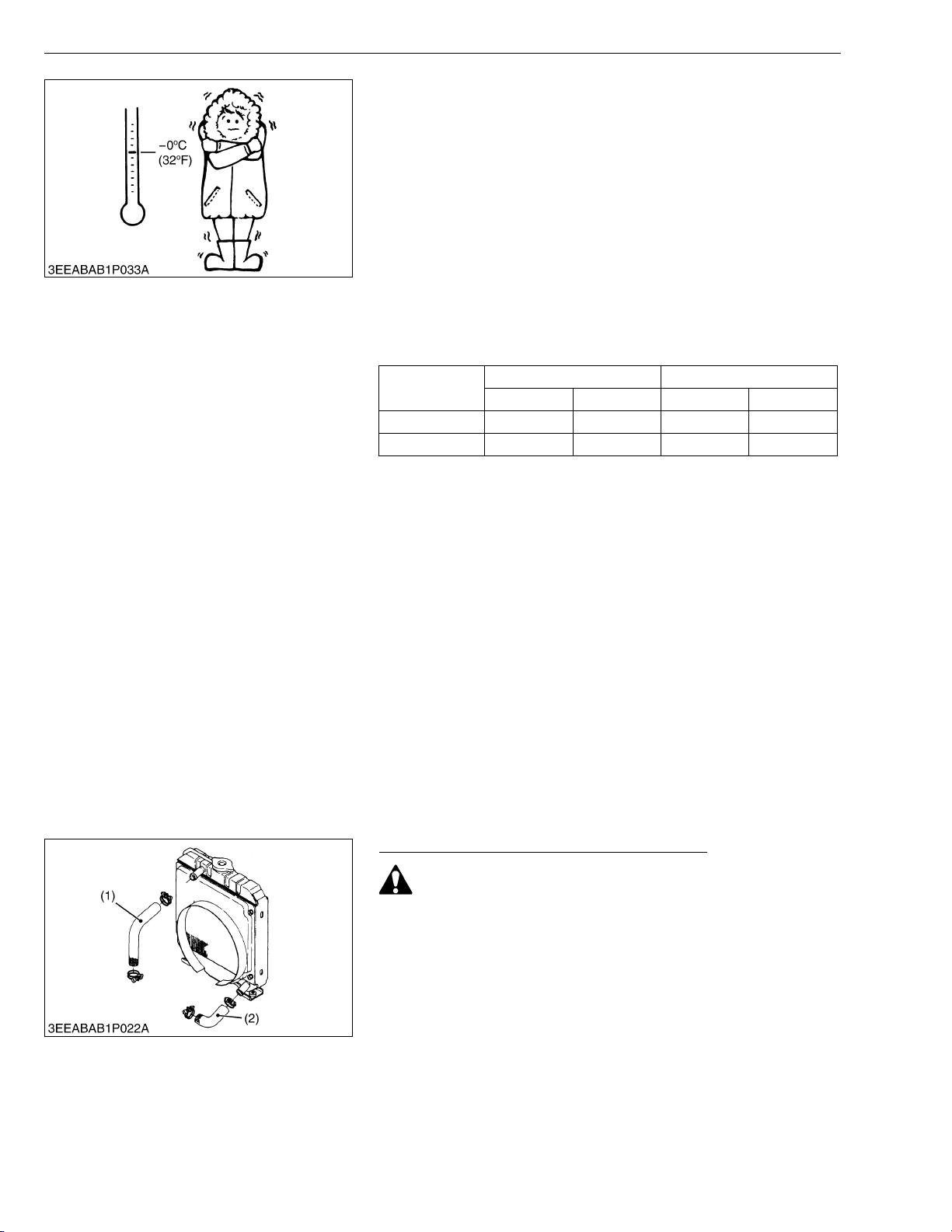
Replacing Radiator Hoses and Clamp Bands
CAUTION
• Do not remove the radiator cap when the engine is hot. Then
loosen cap slightly to the stop to relieve any excess
pressure before removing cap completely.
1. Drain the coolant.
2. Loosen the clamp bands.
3. Remove the upper hose (1) and lower hose (2).
4. Replace new upper / lower hose (1), (2) and clamp bands.
5. Tighten the clamp bands.
6. Fill with clean water and anti-freeze until the coolant level is just
below the port. Install the radiator cap securely.
(1) Upper Hose (2) Lower Hose
W1024178
G-26
Page 37
V3307-DI-T-E2B, WSM
KiSC issued 01, 2009 A
G GENERAL
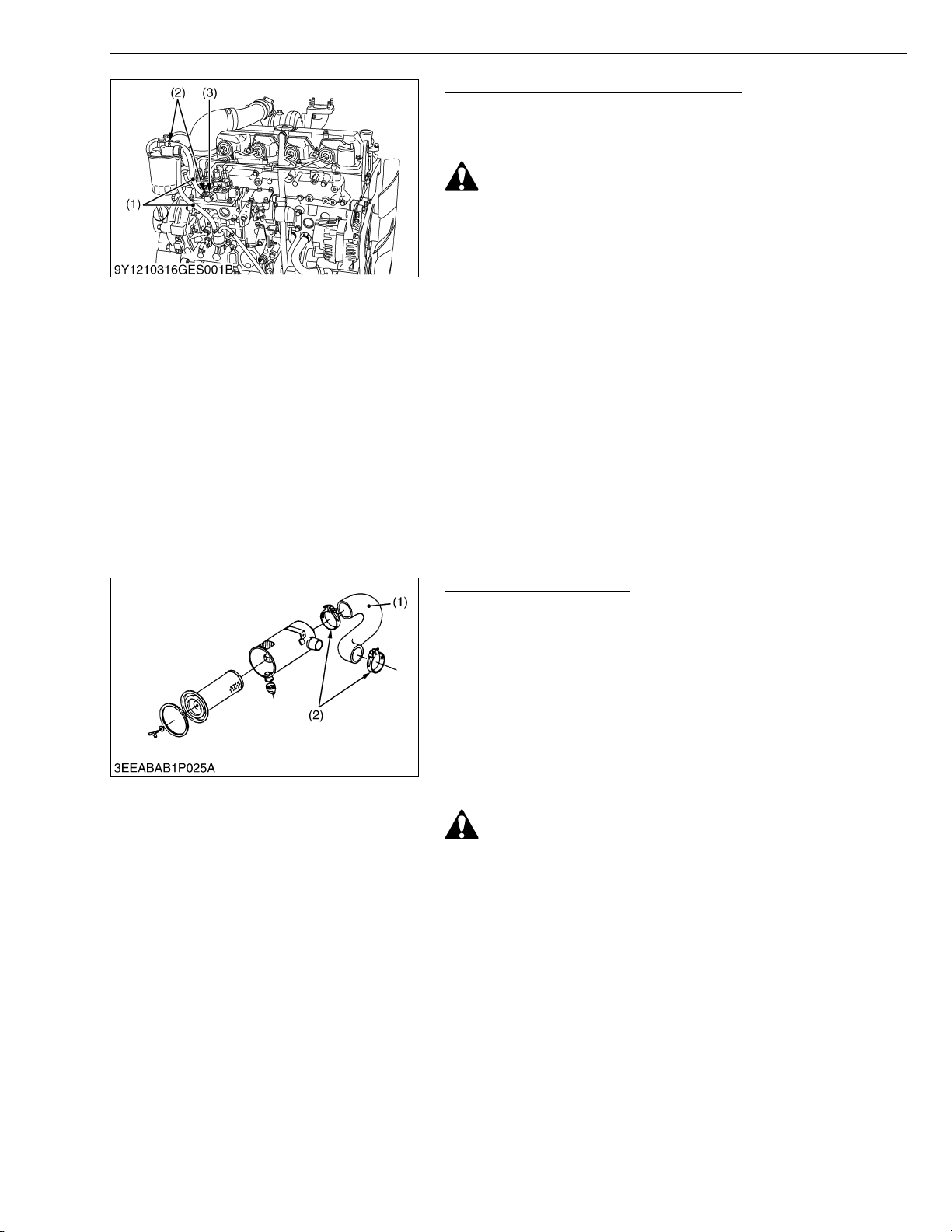
Replacing Fuel Hoses and Clamp Bands
1. Loosen the clamp band (2) and remove the fuel hose (1).
2. Replace new fuel hose (1) and new clamp band (2).
3. Tighten the clamp band (2).
CAUTION
• Stop the engine when attempting the check and change
prescribed above.
(When bleeding fuel system)
1. Fill the tank with fuel and open the cock.
2. Loosen the air vent coupling bolt of fuel filter a few turns.
3. When there is no more air bubbles in the fuel coming out of this
coupling bolt, tighten the coupling bolt.
4. Open the air vent cock (3) on the top of fuel injection pump.
5. If equipped electrical fuel feed pump, turn the key on AC position
and pump the fuel up for 10 to 15 seconds.
If equipped mechanical fuel feed pump, set the stop lever on stop
position and crank the engine for 10 to 15 seconds.
6. Close securely the air vent cock (3) after air bleeding.
IMPORTANTQ
• Except when venting the air, be sure to keep closed the air
vent coupling bolt of the fuel injection pump. Otherwise, the
engine may stall.
(1) Fuel Hose
(2) Clamp Band
(3) Air Vent Cock
W1020090
Replacing Intake Air Line
1. Loosen the clamp bands (2).
2. Remove the intake air hose (1) and clamp bands (2).
3. Replace new intake air hose (1) and new clamp bands (2).
4. Tighten the clamp bands (2).
NOTEQ
• To prevent serious damage to the engine, keep out any dust
inside the intake air line.
(1) Intake Air Hose (2) Clamp Band
W1023867
Replacing Battery
CAUTION
• When the battery is being activated, hydrogen and oxygen
gases in the battery are extremely explosive. Keep open
sparks and flames away from the battery at all times,
especially when charging the battery.
• When charging battery, remove battery vent plugs.
• When disconnecting the cable from the battery, start with
the negative terminal first. When connecting the cable to the
battery, start with the positive terminal first.
• Never check battery charge by placing a metal object across
the posts.
1. Disconnect the negative terminal and positive terminal.
2. Remove the battery holder.
3. Remove the used battery.
4. Replace the new battery.
5. Tighten the battery holder.
6. Connect the positive terminal.
7. Connect the negative terminal.
W1023996
G-27
Page 38
V3307-DI-T-E2B, WSM
KiSC issued 01, 2009 A
5. SPECIAL TOOLS
G GENERAL
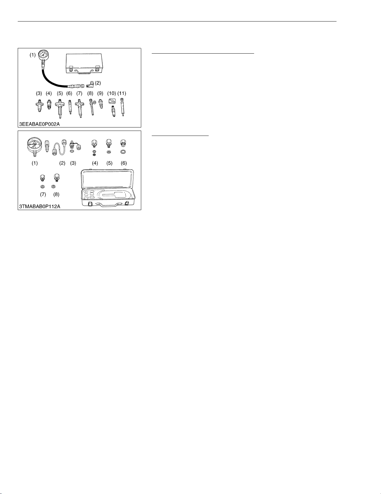
Diesel Engine Compression Tester
Code No : 07909-30208 (Assembly)
Application : Use to measure diesel engine compression and
diagnostics of need for major overhaul.
(1) Gauge
(2) L Joint
(3) Adaptor A
(4) Adaptor B
(5) Adaptor C
(6) Adaptor E
(7) Adaptor F
(8) Adaptor G
(9) Adaptor H
(10) Adaptor I
(11) Adaptor J
W1024200
Oil Pressure Tester
Code No : 07916-32032
Application : Use to measure lubricating oil pressure.
(1) Gauge
(2) Cable
(3) Threaded Joint
(4) Adaptor 1
(5) Adaptor 2
(6) Adaptor 3
(7) Adaptor 4
(8) Adaptor 5
W1024318
G-28
Page 39
V3307-DI-T-E2B, WSM
KiSC issued 01, 2009 A
NOTEQ
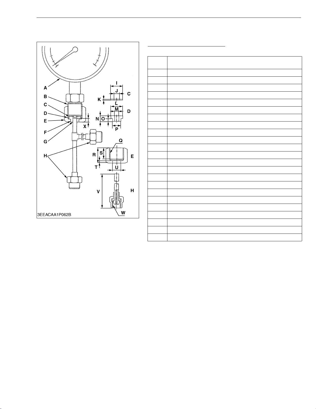
• The following special tools are not provided, make them referring to the figure.
Injection Pump Pressure Tester
Application : Use to check fuel tightness of injection pumps.
Pressure gauge full scale : More than 29.4 MPa
A
(300 kgf/cm
B PF 1/2
C Copper gasket
D Flange (Material Steel)
E Hex. nut 27 mm (1.1 in.) across the plat
F Adhesive application
G Fillet welding on the enter circumference
H Retaining nut
I 17 mm dia. (0.67 in. dia.)
J 8.0 mm dia. (0.31 in. dia.)
K 1.0 mm (0.039 in.)
L 17 mm dia. (0.67 in. dia.)
M 6.10 to 6.20 mm dia. (0.241 to 0.244 in. dia.)
N 8.0 mm (0.31 in.)
O 4.0 mm (0.16 in.)
P 11.97 to 11.99 mm dia. (0.4713 to 0.4720 in. dia.)
Q PF 1/2
R 23 mm (0.91 in.)
S 17 mm (0.67 in.)
T 4.0 mm (0.16 in.)
U 12.00 to 12.02 mm dia. (0.4725 to 0.4732 in. dia.)
V 100 mm (3.94 in.)
W M12 × P1.5
X 5.0 mm (0.20 in.)
2
, 4270 psi)
G GENERAL
W10252400
G-29
Page 40
V3307-DI-T-E2B, WSM
KiSC issued 01, 2009 A
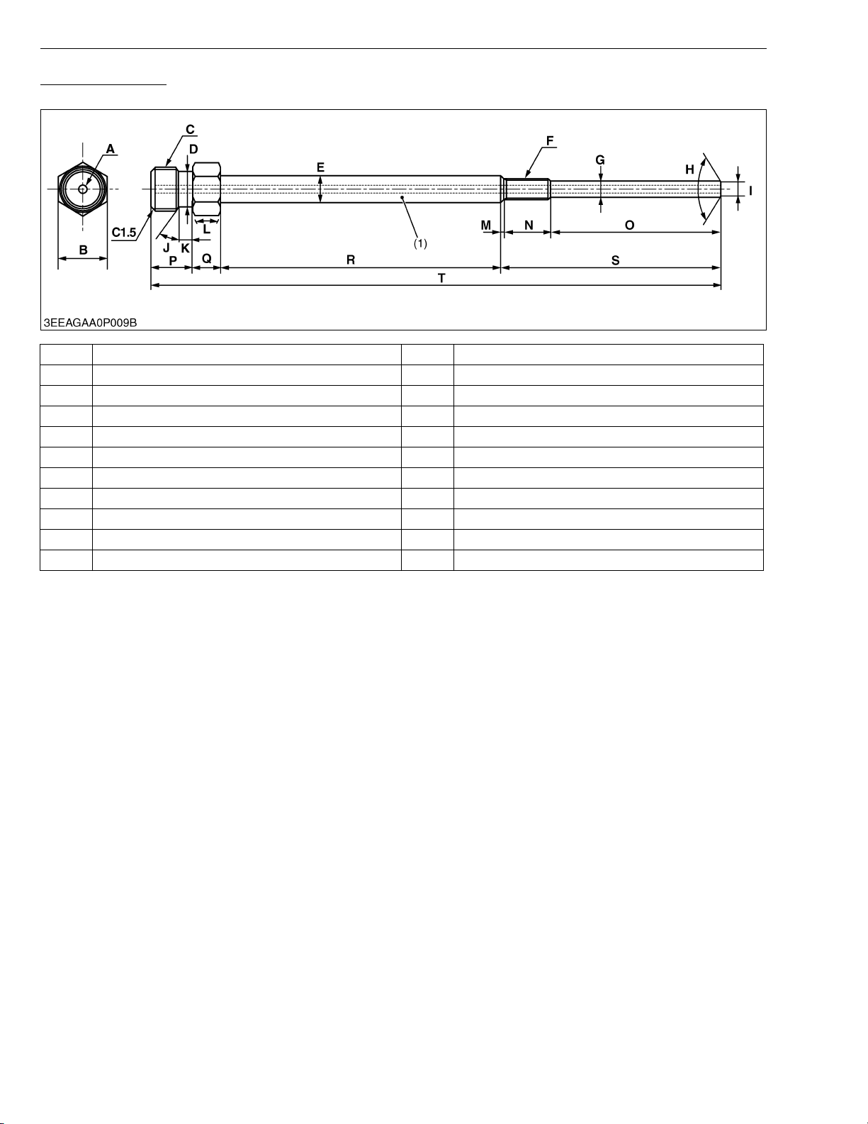
Glow Plug Adapter
Application : Use to check compression pressure through glow plug hole.
A 3.0 mm dia. (0.12 in. dia.) through hole L 1.0 rad (60 °)
B 17.0 mm (0.669 in.) M 1.0 mm (0.039 in.)
C 16.0 mm dia. (0.630 in. dia.) P0.5 N 17.0 mm (0.669 in.)
D 13.0 mm dia. (0.512 in. dia.) O 61.5 mm (2.42 in.)
E 9.5 mm dia. (0.37 in. dia.) P 15.0 mm (0.591 in.)
F M8 x 1.0 Q 10.0 mm (0.394 in.)
G 6.50 to 6.70 mm dia. (0.256 to 0.263 in. dia.) R 100 mm (3.94 in.)
H 2.145 to 2.148 rad (122.9 to 123.1 °) S 79.5 mm (3.13 in.)
I 4.90 to 5.50 mm dia. (0.193 to 0.216 in. dia.) T 204.5 mm (8.051 in.)
J 0.52 rad (30 °) C1.5 Chamfer 1.5 mm (0.059 in.)
K 5.0 mm (0.20 in.)
G GENERAL
(1) Material : SS400
G-30
Page 41
V3307-DI-T-E2B, WSM
KiSC issued 01, 2009 A
G GENERAL
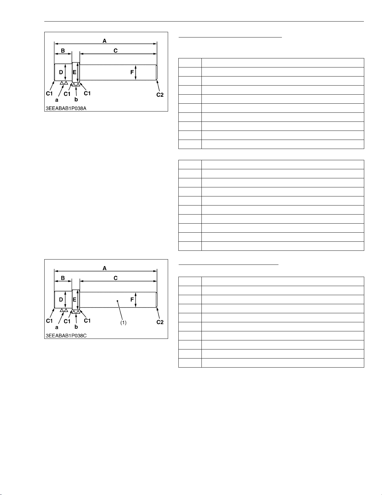
Small End Bushing Replacing Tool
Application : Use to press out and to press fit the small end bushing.
[Press out]
A 157 mm (6.181 in.)
B 14.0 mm (0.5512 in.)
C 120 mm (4.7244 in.)
D 27.4 mm dia. (1.0787 in. dia.)
E 30.95 mm dia. (1.2185 in. dia.)
F 20 mm dia. (0.7874 in. dia.)
a 6.3 μm (250 μin.)
b 6.3 μm (250 μin.)
C1 Chamfer 1.0 mm (0.039 in.)
C2 Chamfer 2.0 mm (0.079 in.)
[Press fit]
A 157 mm (6.181 in.)
B 14.0 mm (0.5512 in.)
C 120 mm (4.7244 in.)
D 27.4 mm dia. (1.0787 in. dia.)
E 42.000 mm dia. (1.6535 in. dia.)
F 20 mm dia. (0.7874 in. dia.)
a 6.3 μm (250 μin.)
b 6.3 μm (250 μin.)
C1 Chamfer 1.0 mm (0.039 in.)
C2 Chamfer 2.0 mm (0.079 in.)
W1040702
Idle Gear Bushing Replacing Tool
Application : Use to press out and to press fit the bushing.
A 196 mm (7.72 in.)
B 25.0 mm (0.984 in.)
C 150 mm (5.91 in.)
D 34.5 mm dia. (1.36 in. dia.)
E 38.075 to 38.100 mm dia. (1.4991 to 1.5000 in. dia.)
F 20 mm dia. (0.79 in. dia.)
a 6.3 μm (250 μin.)
b 6.3 μm (250 μin.)
C1 Chamfer 1.0 mm (0.039 in.)
C2 Chamfer 2.0 mm (0.079 in.)
(1) Material : SS400
W1039429
G-31
Page 42
V3307-DI-T-E2B, WSM
KiSC issued 01, 2009 A
G GENERAL
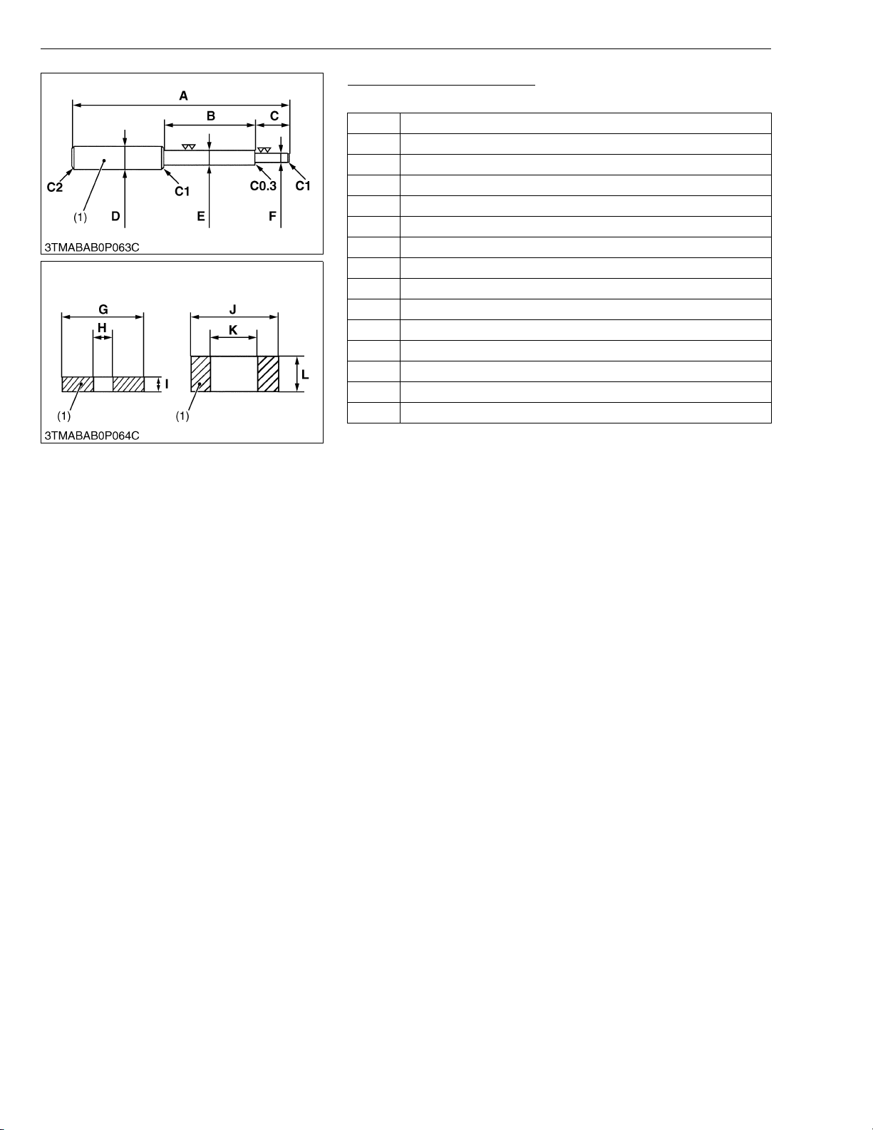
Valve Guide Replacing Tool
Application : Use to press out and press fit the valve guide.
A 225 mm (8.86 in.)
B 70 mm (2.8 in.)
C 45 mm (1.8 in.)
D 20 mm dia. (0.79 in dia.)
E 11.7 to 11.9 mm dia. (0.461 to 0.468 in. dia.)
F 6.50 to 6.60 mm dia. (0.256 to 0.259 in. dia.)
G 25 mm dia. (0.98 in. dia.)
H 6.70 to 7.00 mm dia. (0.264 to 0.275 in. dia.)
I 5.0 mm (0.20 in.)
J 20 mm dia. (0.79 in. dia.)
K 12.5 to 12.8 mm dia. (0.493 to 0.503 in. dia.)
L 8.50 to 8.90 mm (0.335 to 0.350 in.)
C1 Chamfer 1.0 mm (0.039 in.)
C2 Chamfer 2.0 mm (0.079 in.)
C0.3 Chamfer 0.30 mm (0.012 in.)
(1) Material : SS400
W10250170
G-32
Page 43
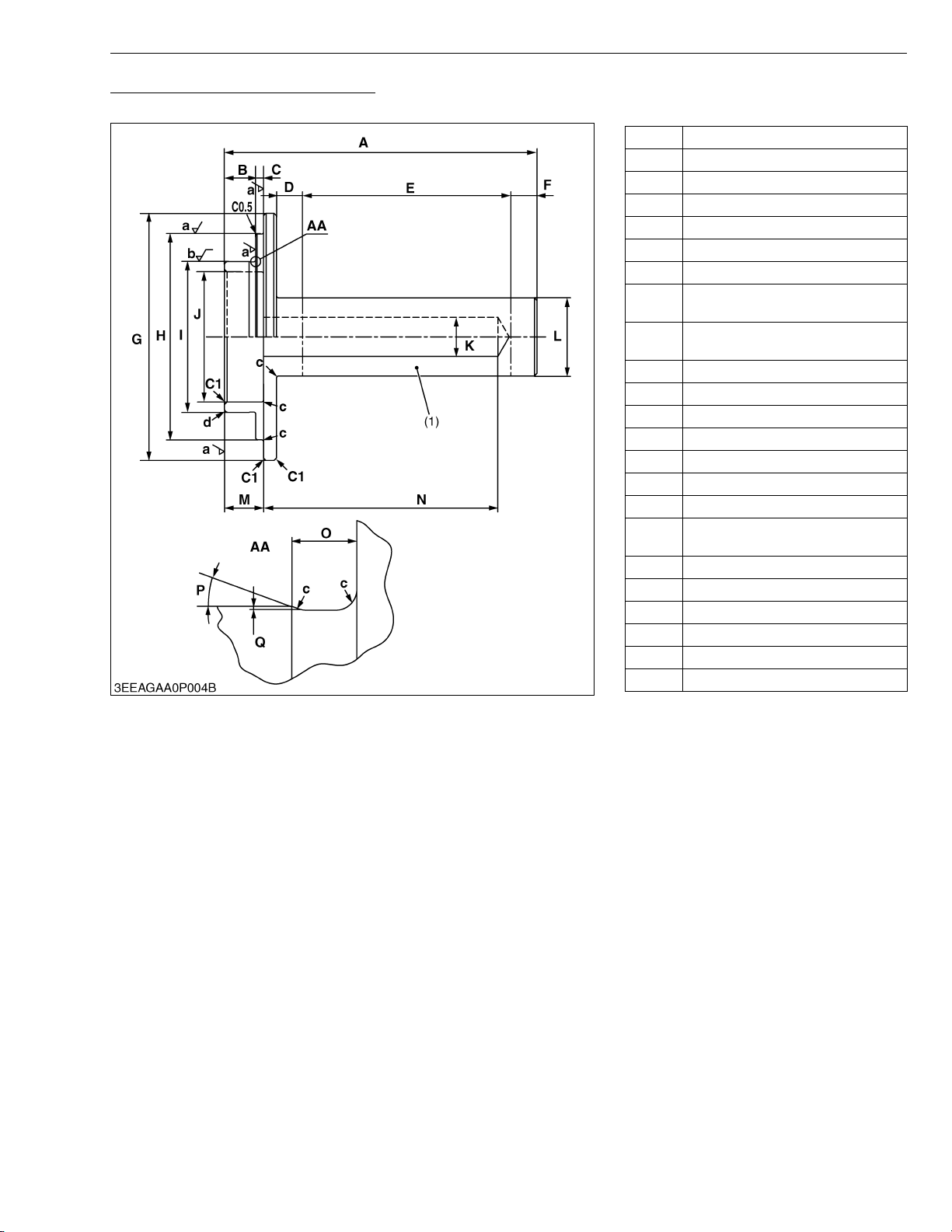
V3307-DI-T-E2B, WSM
KiSC issued 01, 2009 A
Front Cover Oil Seal Replacing Tool
Application : Use to press fit the front cover oil seal.
G GENERAL
A 120 mm (4.72 in.)
B 12.0 mm (0.472 in.)
C 2.90 to 3.00 mm (0.115 to 0.118 in.)
D 10.0 mm (0.394 in.)
E 80.0 mm (3.15 in.)
F 10.0 mm (0.394 in.)
G 95.0 mm dia. (3.74 in. dia.)
78.900 to 79.100 mm dia.
H
(3.1063 to 3.1141 in. dia.)
57.971 to 57.990 mm dia.
I
(2.2824 to 2.2830 in. dia.)
J 50.0 mm dia. (1.97 in. dia.)
K 15.0 mm dia. (0.591 in. dia.)
L 30.0 mm dia. (1.18 in. dia.)
M 15.0 mm (0.591 in.)
N 90.0 mm (3.54 in.)
O 2.50 mm (0.0984 in.)
P 0.35 rad (20 °)
0.15 to 0.25 mm
Q
(0.0059 to 0.0098 in.)
a Ra = 3.2 a
b Ra = 1.6 a
c 0.80 mm radius (0.031 in. radius)
d 1.5 mm radius (0.059 in. radius)
C0.5 Chamfer 0.50 mm (0.020 in.)
C1 Chamfer 1.0 mm (0.039 in.)
(1) Material : S43C-D
W1014589
G-33
Page 44
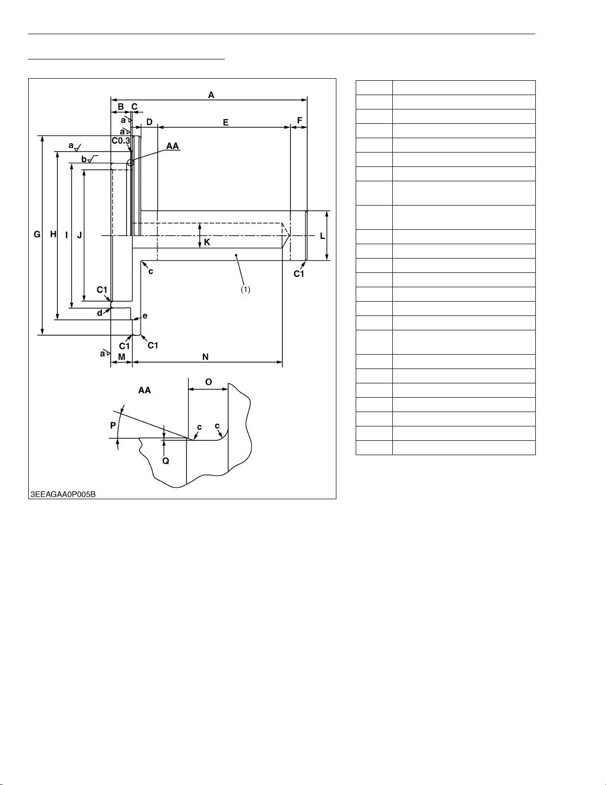
V3307-DI-T-E2B, WSM
KiSC issued 01, 2009 A
Flywheel Housing Oil Seal Replacing Tool
Application : Use to press fit the flywheel housing oil seal.
G GENERAL
A 118 mm (4.65 in.)
B 12.0 mm (0.472 in.)
C 0.90 to 1.0 mm (0.036 to 0.039 in.)
D 10.0 mm (0.394 in.)
E 80.0 mm (3.15 in.)
F 10.0 mm (0.394 in.)
G 120 mm dia. (4.72 in. dia.)
100.90 to 101.10 mm dia.
H
(3.9725 to 3.9803 in. dia.)
86.966 to 86.988 mm dia.
I
(3.4239 to 3.4247 in. dia.)
J 79.0 mm dia. (3.11 in. dia.)
K 15.0 mm dia. (0.591 in. dia.)
L 30.0 mm dia. (1.18 in. dia.)
M 13.0 mm (0.512 in.)
N 90.0 mm (3.54 in.)
O 2.50 mm (0.0984 in.)
P 0.35 rad (20 °)
0.15 to 0.25 mm
Q
(0.0059 to 0.0098 in.)
a Ra = 3.2 a
b Ra = 1.6 a
c 0.80 mm radius (0.031 in. radius)
d 1.5 mm radius (0.059 in. radius)
e 0.20 mm radius (0.0079 in. radius)
C0.3 Chamfer 0.30 mm (0.012 in.)
C1 Chamfer 1.0 mm (0.039 in.)
(1) Material : S43C-D
W1015151
G-34
Page 45
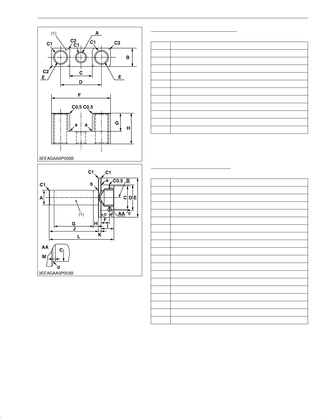
V3307-DI-T-E2B, WSM
KiSC issued 01, 2009 A
G GENERAL
Valve Bridge Shaft Replacing Tool
Application : Use to press fit the valve bridge shaft.
A 9.50 mm dia. (0.374 in. dia.) through hole
B 19.0 mm (0.748 in.)
C 23.2 mm (0.913 in.)
D 42.00 to 42.40 mm (1.654 to 1.669 in.)
E 12.5 mm dia. (0.492 in. dia.) through hole
F 61.0 mm (2.40 in.)
G 18.7 mm (0.736 in.)
H 30.90 to 31.70 mm (1.217 to 1.248 in.)
a 0.30 mm radius (0.012 in. radius)
C0.5 Chamfer 0.50 mm (0.020 in.)
C1 Chamfer 1.0 mm (0.039 in.)
C2 Chamfer 2.0 mm (0.079 in.)
(1) Material : SS400
W1015898
Camshaft Cover Replacing Tool
Application : Use to press fit the camshaft cover.
A 30.0 mm (1.18 in.)
B 30.0 mm dia., 20.0 mm depth (1.18 in. dia., 0.79 in. depth)
C 47.975 to 48.000 mm (1.8888 to 1.8897 in.)
D 52.0 mm (2.05 in.)
E 80.0 mm (3.15 in.)
F 16.5 to 16.6 mm (0.650 to 0.653 in.)
G 80.0 mm (3.15 in.)
H 10.0 mm (0.394 in.)
I 26.0 mm (1.02 in.)
J 100 mm (3.94 in.)
K 6.0 mm (0.24 in.)
L 132 mm (5.20 in.)
M 1.0 mm (0.039 in.)
a 1.0 mm radius (0.039 in. radius)
b 2.0 mm radius (0.079 in. radius)
c Ra = 3.2a
d 0.40 mm radius (0.016 in. radius)
C0.5 Chamfer 0.50 mm (0.020 in.)
C1z Chamfer 1.0 mm (0.039 in.)
(1) Material : S43C
W1014056
G-35
Page 46
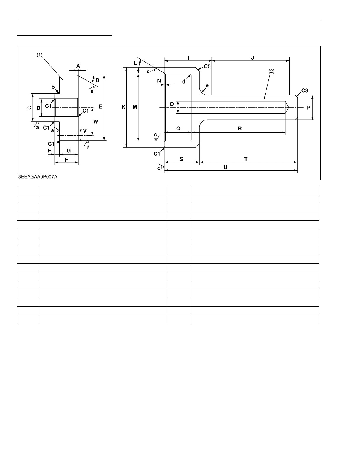
V3307-DI-T-E2B, WSM
KiSC issued 01, 2009 A
Crankshaft Sleeve Replacing Tool
Application : Use to fix the crankshaft sleeve of the diesel engine.
G GENERAL
A 1.50 mm (0.0591 in.) Q 33.0 mm (1.30 in.)
B 0.52 rad (30 °) R 115 mm depth (4.53 in. depth)
C 34.925 to 34.950 mm dia. (1.3750 to 1.3759 in. dia.) S 43.0 mm (1.69 in.)
D 22 mm dia. (0.8661 in. dia.) T 120 mm (4.72 in.)
E 81.980 to 81.985 mm dia. (3.2276 to 3.2277 in. dia.) U 163 mm (6.42 in.)
F 6.0 mm (0.24 in.) V 8.0 mm dia. (0.31 in. dia.)
G 23.5 mm (0.925 in.) W 33.475 to 33.525 mm (1.3180 to 1.3198 in.)
H 29.5 mm (1.16 in.) a Ra = 1.6 a
I 58.0 mm (2.28 in.) b 0.50 mm radius (0.020 in. radius)
J 95.0 mm (3.74 in.) c Ra = 3.2 a
K 98.0 mm dia. (3.86 in. dia.) d 1.50 mm radius (0.0591 in. radius)
L 0.52 rad (30 °) e 10.0 mm radius (0.394 in. radius)
M 82.100 to 82.200 mm dia. (3.2323 to 3.2362 in. dia.) C1 Chamfer 1.0 mm (0.039 in.)
N 1.50 mm (0.0591 in.) C3 Chamfer 3.0 mm (0.12 in.)
O 15.0 mm dia. (0.591 in. dia.) C5 Chamfer 5.0 mm (0.20 in.)
P 30.0 mm dia. (1.18 in. dia.)
(1) Sleeve Guide Material : S43C (2) Shaft Material : S43C
G-36
Page 47
V3307-DI-T-E2B, WSM
KiSC issued 01, 2009 A
G GENERAL
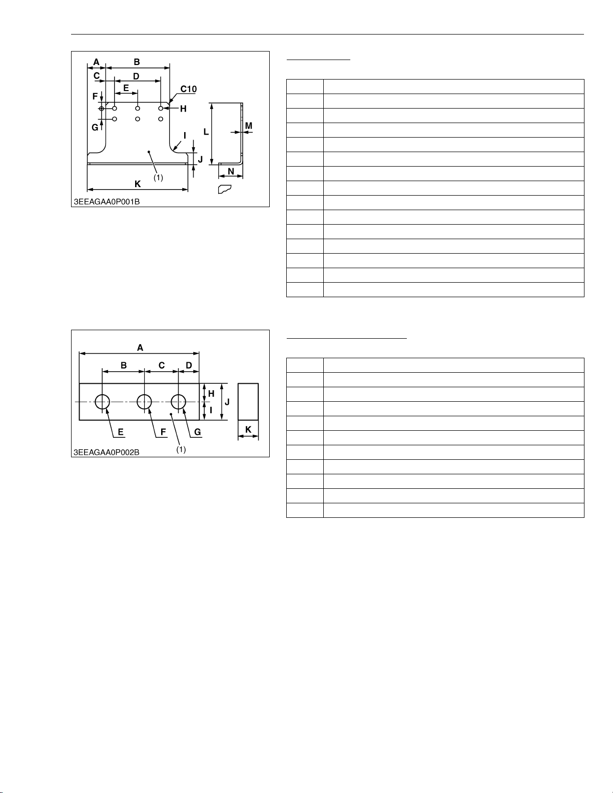
Engine Stand
Application : Use to support engine.
A 107 mm (4.21 in.)
B 246 mm (9.68 in.)
C 21 mm (0.83 in.)
D 204 mm (8.03 in.)
E 102 mm (4.02 in.)
F 15 mm (0.59 in.)
G 59 mm (2.3 in.)
H 14 mm dia. (0.55 in. dia.)
I 80 mm radius (3.1 in. radius)
J 70 mm (2.8 in.)
K 460 mm (18.1 in.)
L 270 mm (10.6 in.)
M 6.0 mm (0.24 in.)
N 70 mm (2.8 in.)
C10 Chamfer 10 mm (0.39 in.)
(1) Material : S43C
W1033645
Crankcase Aligning Plate
Application : Use for aligning the crankcase 1 and 2.
A 126.6 mm (4.984 in.)
B 49.1 mm (1.93 in.)
C 37.5 mm (1.48 in.)
D 20 mm (0.79 in.)
E 14 mm dia. (0.55 in. dia.)
F 14 mm dia. (0.55 in. dia.)
G 14 mm dia. (0.55 in. dia.)
H 17.5 mm (0.689 in.)
I 17.5 mm (0.689 in.)
J 35 mm (1.4 in.)
K 19 mm (0.75 in.)
(1) Material : S43C
W1047882
G-37
Page 48
V3307-DI-T-E2B, WSM
KiSC issued 01, 2009 A
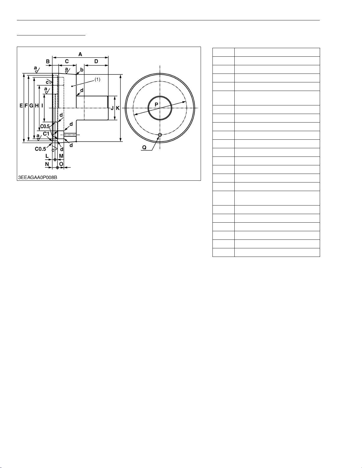
Flywheel Housing Guide
Application : Use to install the flywheel housing to the crankcase.
G GENERAL
A 70.0 mm (2.76 in.)
B 8.0 mm (0.31 in.)
C 22.0 mm (0.866 in.)
D 30.0 mm (1.18 in.)
E 87.0 mm dia. (3.43 in. dia.)
82.036 to 82.071 mm dia.
F
(3.2298 to 3.2311 in. dia.)
G 77.0 mm dia. (3.03 in. dia.)
H 57.0 mm dia. (2.24 in. dia.)
I 35.0 mm dia. (1.38 in. dia.)
J 30.0 mm dia. (1.18 in. dia.)
K 84.0 mm dia. (3.31 in. dia.)
L 3.5 mm (0.14 in.)
M 3.0 mm (0.12 in.)
N 6.60 to 6.80 mm (0.260 to 0.267 in.)
O 8.0 mm (0.31 in.)
P 67.0 mm dia. (2.64 in. dia.)
4.0 mm dia. (0.16 in. dia.)
Q
through hole
a Ra = 1.6 a
b 1.5 mm radius (0.059 in. radius)
c Ra = 3.2 a
d 0.80 mm radius (0.031 in. radius)
C0.5 Chamfer 0.50 mm (0.020 in.)
C1 Chamfer 1.0 mm (0.039 in.)
(1) Material : SS400
W1017819
G-38
Page 49
V3307-DI-T-E2B, WSM
KiSC issued 01, 2009 A
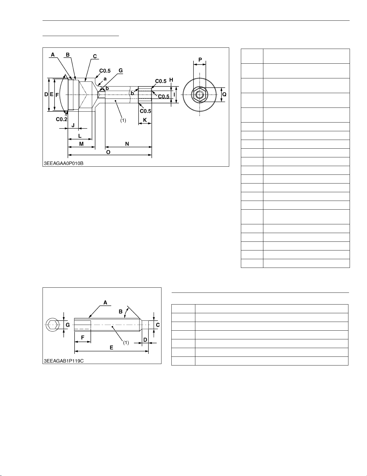
Injection Pump Gear Puller
Application : Use for remove the injection pump gear from governor shaft.
G GENERAL
M35 x P1.5, 6.0 mm depth
A
(0.24 in. depth)
35.0 mm dia., 12.0 mm depth
B
(1.38 in. dia., 0.472 in. depth)
30.0 mm dia., 27.5 mm depth
C
(1.18 in. dia., 1.08 in. depth)
40.00 to 40.20 mm dia.
D
(1.575 to 1.582 in. dia.)
35.90 to 36.10 mm dia.
E
(1.414 to 1.421 in. dia.)
F 2.09 rad (120 °)
G M8 x P1.25
H 9.0 mm dia. (0.35 in. dia.)
I 19.0 mm dia. (0.748 in. dia.)
J 12.0 mm (0.472 in.)
K 15.0 mm (0.591 in.)
L 27.5 mm (1.08 in.)
M 31.0 mm (1.22 in.)
N 57.5 mm (2.26 in.)
O 100 mm (3.94 in.)
13.75 to 14.00 mm
P
(0.5414 to 0.5511 in.)
Q 16.17 mm (0.6366 in.)
a 5.0 mm radius (0.20 in. radius)
b 0.40 mm radius (0.016 in. radius)
C0.2 Chamfer 0.20 mm (0.0079 in.)
C0.5 Chamfer 0.50 mm (0.020 in.)
(1) Material : SS400
W1018612
Fuel Camshaft Lock Screw (Socket Set Screw Dog Point Type)
Application : Use to fix the fuel camshaft.
A M8 × Pitch 1.25
B 0.79 rad (45 °)
C 5.0 mm dia. (0.20 in. dia.)
D 4.0 mm (0.16 in.)
E 45 mm (1.8 in.)
F 10 mm (0.39 in.) : Conspicuously Painted
G 5.0 mm (0.20 in.)
(1) Material : SS400
W10461560
G-39
Page 50
V3307-DI-T-E2B, WSM
KiSC issued 01, 2009 A
G GENERAL
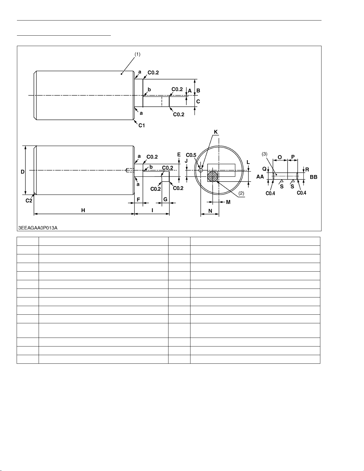
Jig for Governor Connecting Rod
Application : Use for connecting the governor connecting rod to the rack pin of the fuel injection pump assembly.
A 0.50 mm (0.020 in.) O 5.0 mm (0.20 in.)
B 12.7 to 13.0 mm (0.500 to 0.511 in.) P 4.0 mm (0.16 in.)
C 8.70 to 9.00 mm (0.343 to 0.354 in.) Q 2.955 to 2.965 mm dia. (0.1164 to 0.1167 in. dia.)
D 39.0 mm (1.54 in.) R 3.020 to 3.030 mm dia. (0.1189 to 0.1192 in. dia.)
E 10.0 mm (0.394 in.) S Ra = 1.6 a
F 7.0 mm (0.28 in.) AA Governor housing side
G 6.0 mm (0.24 in.) BB Press in side
H 80.0 mm (3.15 in.) a 0.60 mm radius (0.024 in. radius)
I 27.95 to 28.05 mm (1.101 to 1.104 in.) b 1.0 mm radius (0.039 in. radius)
J 5.0 mm (0.20 in.) C0.2 Chamfer 0.20 mm (0.0079 in.)
3.000 to 3.010 mm dia., 6.0 mm depth
K
(0.1182 to 0.1185 in. dia., 0.24 in. depth)
L 9.0 mm (0.35 in.) C0.5 Chamfer 0.50 mm (0.020 in.)
M 5.0 mm (0.20 in.) C1 Chamfer 1.0 mm (0.039 in.)
N 14.45 to 14.55 mm (0.5689 to 0.5728 in.) C2 Chamfer 2.0 mm (0.079 in.)
(1) Material : S43C-D (2) Permanent Magnet :
8.0 mm dia. (0.31 in. dia.)
Thickness : 3.0 mm (0.12 in.)
C0.4 Chamfer 0.40 mm (0.016 in.)
(3) Pin Material : SUM22
G-40
Page 51

MECHANISM
KiSC issued 01, 2009 A
CONTENTS
1. FEATURE ........................................................................................................ M-1
2. ENGINE BODY ............................................................................................... M-2
[1] CYLINDER BLOCK................................................................................... M-2
[2] COOLING JACKET................................................................................... M-3
[3] HALF-FLOATING HEAD COVER ............................................................ M-3
[4] CYLINDER HEAD ..................................................................................... M-4
[5] 4 SCREWS PER EACH CYLINDER ASSEMBLING STRUCTURE .... M-5
[6] CENTER DIRECT INJECTION SYSTEM (E-CDIS)............................... M-6
[7] GEAR TRAIN CONFIGURATION ............................................................ M-7
[8] PISTON...................................................................................................... M-7
[9] BUILT-IN DYNAMIC BALANCER (BALANCER MODEL ONLY) .......... M-7
3. LUBRICATING SYSTEM ................................................................................ M-8
[1] OIL COOLER ............................................................................................ M-8
4. COOLING SYSTEM........................................................................................ M-9
[1] THERMOSTAT .......................................................................................... M-9
[2] BOTTOM BYPASS SYSTEM................................................................. M-10
5. FUEL SYSTEM ............................................................................................. M-11
[1] GOVERNOR ............................................................................................ M-11
[2] 2 STAGE DI NOZZLE ........................................................................... M-14
[3] INJECTION PUMP WITH F.S.P............................................................ M-15
[4] CPV EQUIPPED DELIVERY VALVE.................................................... M-16
6. INTAKE AND EXHAUST SYSTEM ............................................................. M-17
[1] TURBOCHARGER................................................................................... M-17
Page 52
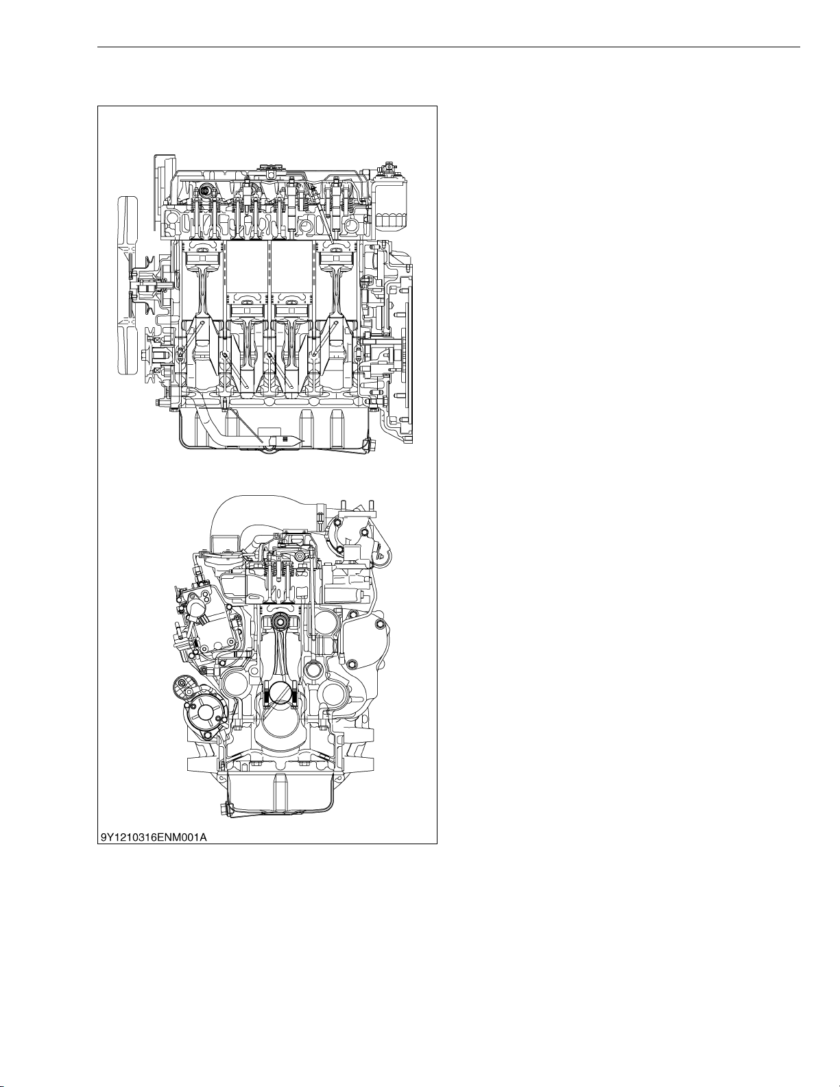
V3307-DI-T-E2B, WSM
KiSC issued 01, 2009 A
1. FEATURE
ENGINE
The 07 series DI engine are the vertical type 4-cycle
diesel engine featuring the advanced performances
shown below.
This is a small sized, high power and environment
conscious engine, which employs the four valve system,
two inlet valves with double ports, and two exhaust
valves with the new E-CDIS. The 07 series DI engine
newly adopted ladder frame crankshaft support
structure, gear train located at flywheel side and coolant
evenness distribution type cooling jacket. Thus, this
engine achieves high combustion efficiency and
complies with various regulations of exhaust gas.
Based upon the conventional model, Kubota
developed a unique governor system and various new
mechanisms which reduces exhaust emission, noise and
vibration and realize durability and high torque.
W1012645
M-1
Page 53
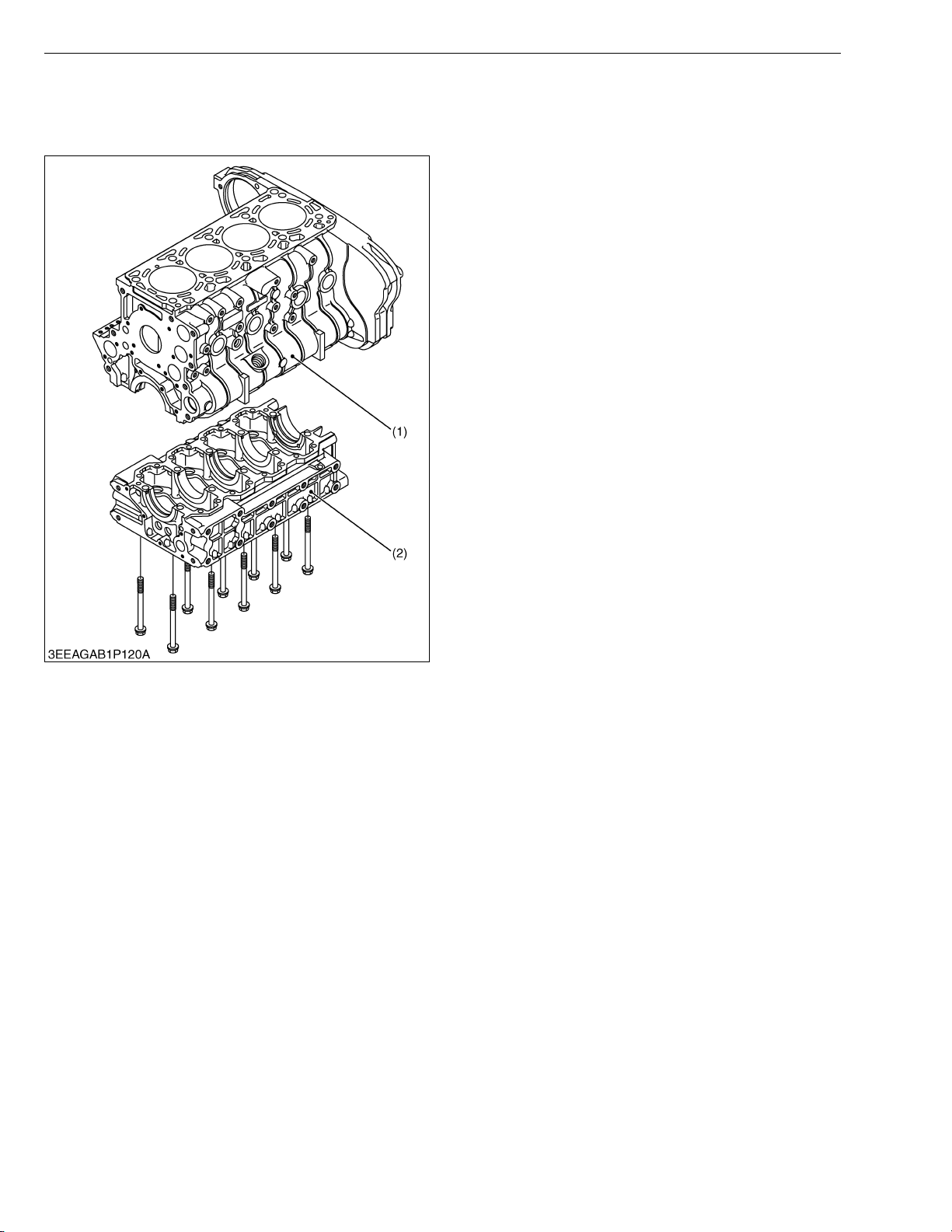
V3307-DI-T-E2B, WSM
KiSC issued 01, 2009 A
2. ENGINE BODY
[1] CYLINDER BLOCK
ENGINE
The 07 series DI engine employs ladder frame
structure type crankcases - the crankcase 1 (1) with
combustion part and the crankcase 2 (2) which supports
the crankcase 1 (1).
The following benefits are in the ladder frame
structure.
1. Minimizing parts.
2. Noise reduction.
3. Reduction of loss and dispersion on friction thanks to
accuracy of axial concentricity.
The cylinder is a linerless type which enables good
cooling operation, less strain and good abrasion
resistance.
(1) Crankcase 1 (2) Crankcase 2
W1012790
M-2
Page 54
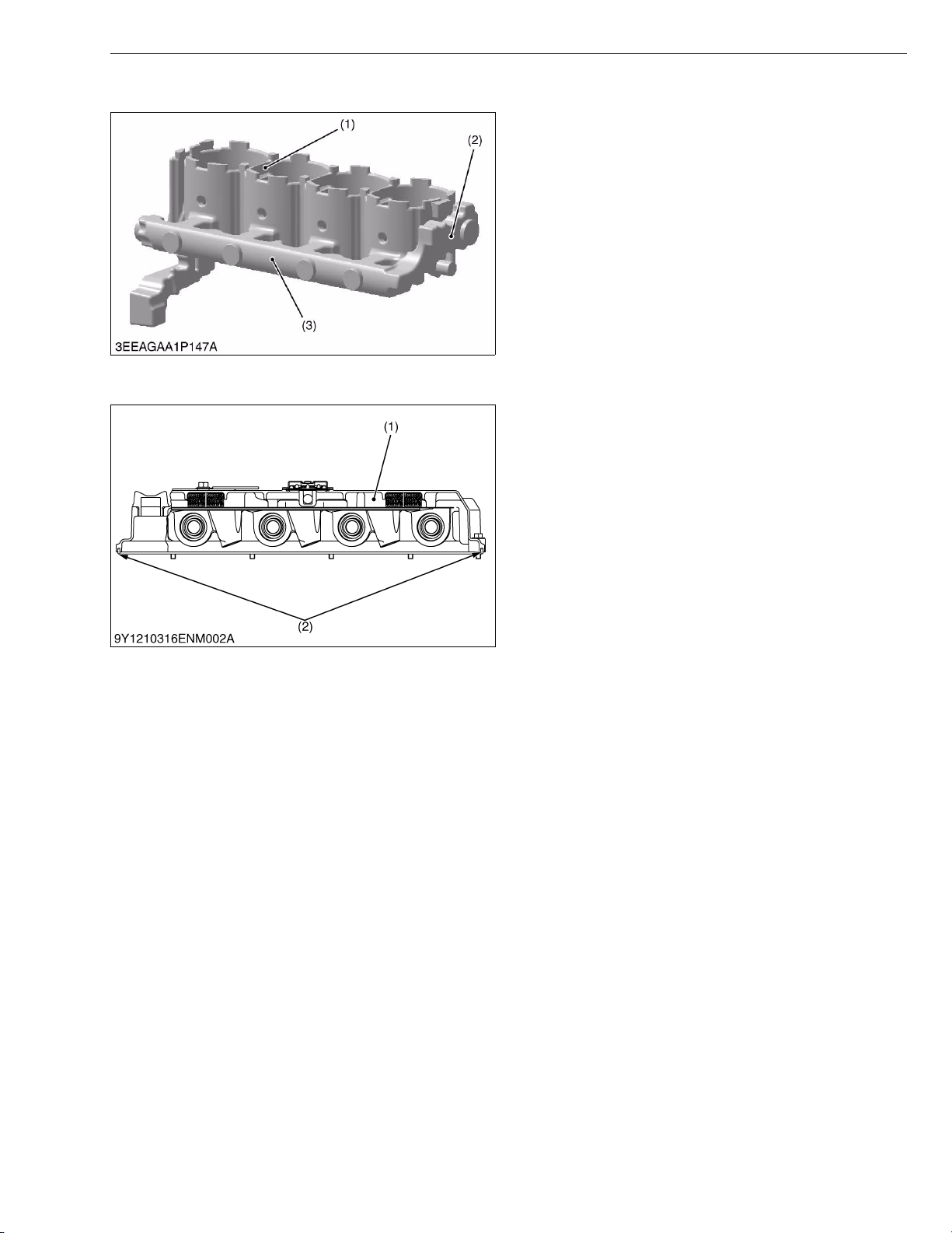
V3307-DI-T-E2B, WSM
KiSC issued 01, 2009 A
[2] COOLING JACKET
[3] HALF-FLOATING HEAD COVER
ENGINE
The 07 series DI engine employs coolant evenness
distribution type cooling jacket inside crankcase 1. The
coolant is evenly supplied to each cylinder through the
main gallery (3) in the jacket mold core (2).
(1) Coolant Passage between
Cylinder
(2) Jacket Mold Core
(3) Main Gallery
W1013000
The rubber packing (2) is fitted in to maintain the head
cover 0.5 mm (0.02 in.) or so off the cylinder head. This
arrangement helps reduce noise coming from the
cylinder head.
(1) Cylinder Head Cover (2) Rubber Packing
W1013327
M-3
Page 55
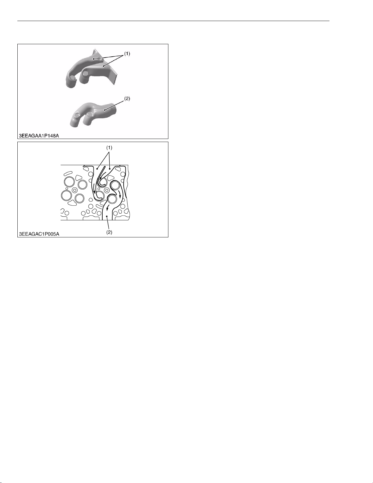
V3307-DI-T-E2B, WSM
KiSC issued 01, 2009 A
[4] CYLINDER HEAD
ENGINE
This engine employs four valve system, the cylinder
head is provided with double intake passage in order to
ensure appropriate air suction and give an optimum swirl.
(1) Intake (2) Exhaust
W1013336
M-4
Page 56
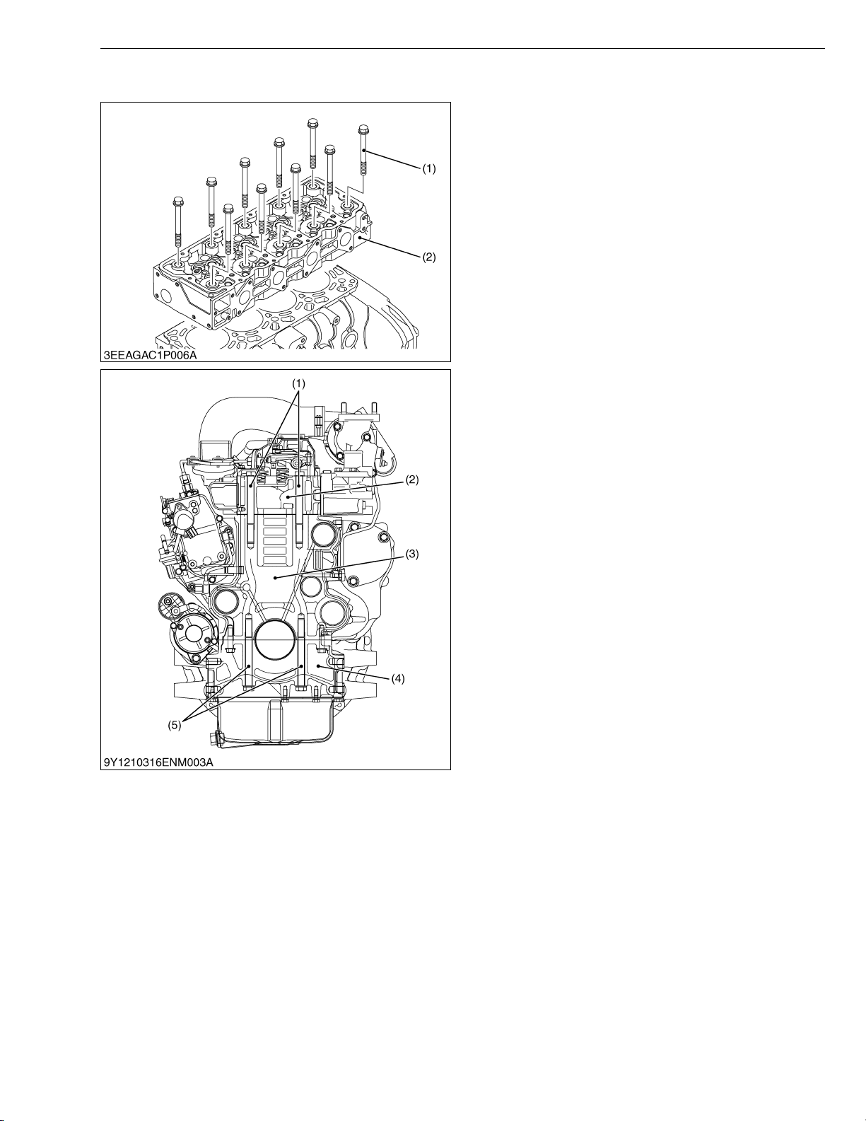
V3307-DI-T-E2B, WSM
KiSC issued 01, 2009 A
[5] 4 SCREWS PER EACH CYLINDER ASSEMBLING STRUCTURE
The 07 series DI engine employs 4 screws per each
cylinder assembling structure.
The cylinder head (2) and the crankcase 2 (4) are
assembled from the top and bottom to the crankcase 1
(3) with each of 10 screws.
The following objectives are in the 4 screws per each
cylinder assembling structure.
1. Reduce the load share rate of combustion pressure
on outer block surface wall.
2. Flexibility of cylinder head design.
(1) Cylinder Head Mounting
Screw
(2) Cylinder Head
(3) Crankcase 1
(4) Crankcase 2
(5) Crankcase 2 Mounting Screw
ENGINE
W1013265
M-5
Page 57
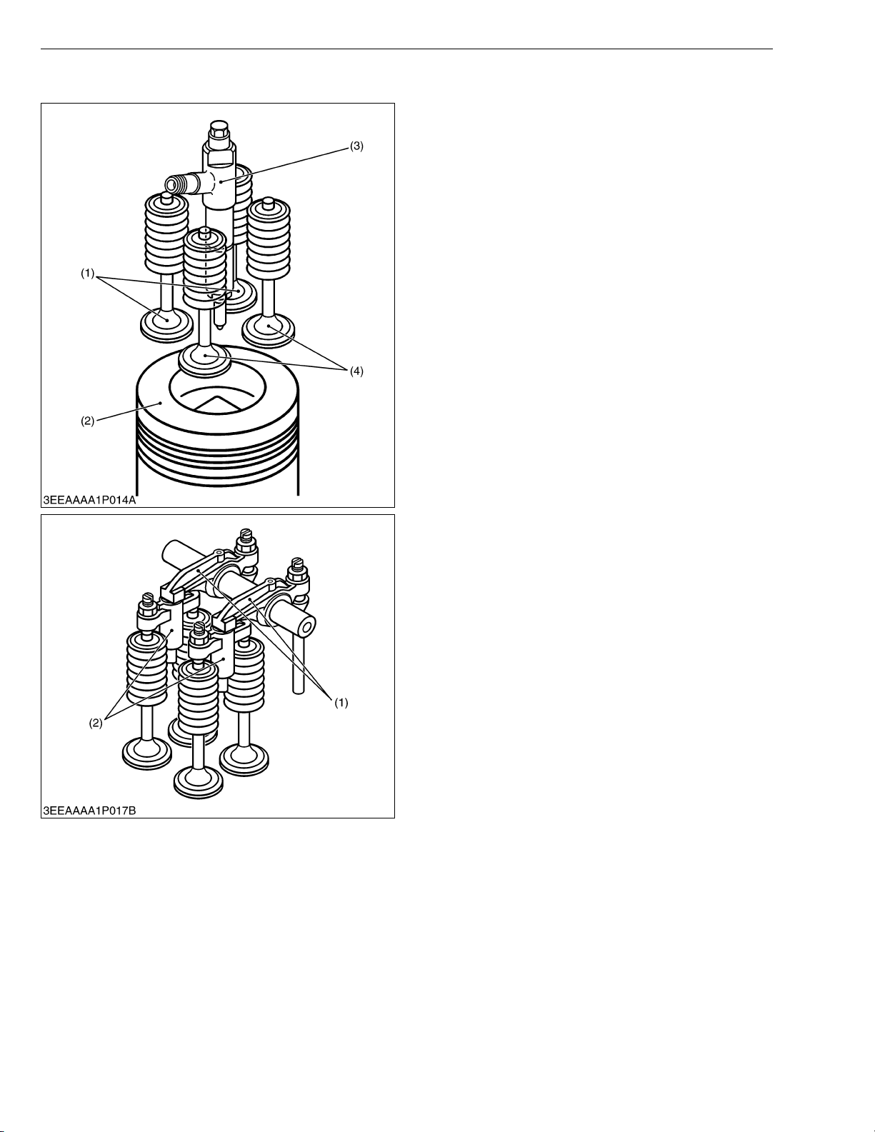
V3307-DI-T-E2B, WSM
KiSC issued 01, 2009 A
[6] CENTER DIRECT INJECTION SYSTEM (E-CDIS)
The 07 series DI engine adopts the Center Direct
Injection System (E-CDIS), in which the injection nozzle
(3) is positioned upright at the center of the cylinder.
This system serves to inject fuel directly at the center
of the cylinder. By so doing, injected fuel and suction air
can be mixed more uniformly, leading to more stable,
higher combustion performance. In other words, cleaner
emission, higher power output, lower fuel consumption,
lower operating noise and higher start-up performance
have been achieved.
(1) Exhaust Valves
(2) Piston
ENGINE
(3) Injection Nozzle
(4) Intake Valves
W11094950
The 07 series DI engine has two intake valves and
two exhaust valves per each cylinder.
The rocker arm (1) contacts a valve bridge arm (2)
instead of the valves stem tip.
The valve bridge arm (2) then contacts both intake
valves or both exhaust valves and causes two valves to
open simultaneously.
(1) Rocker Arm (2) Valve Bridge Arm
W1014724
M-6
Page 58
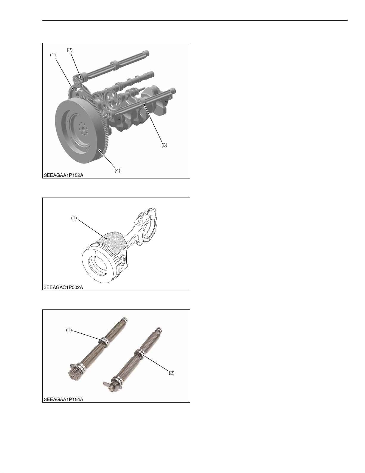
V3307-DI-T-E2B, WSM
KiSC issued 01, 2009 A
[7] GEAR TRAIN CONFIGURATION
[8] PISTON
ENGINE
The 07 series DI engine employs gear train located at
flywheel side. The following benefits are in the rear gear
train configuration.
1. Flexibility of auxiliary parts arrangement.
2. Reduction of gear chattering noise from crankshaft of
torsional and bending vibration.
(1) Rear Gear Train
(2) Balancer Shaft 1 (Option)
(3) Balancer Shaft 2 (Option)
(4) Flywheel
W1013611
Piston’s skirt is coated with molybdenum
disulfide+, which reduces the piston slap noise and
thus the entire operating noise.
+Molybdenum disulfide (MoS
2)
The molybdenum disulfide (1) serves as a solid
lubricant, like a Graphite or Teflon. This material helps
resist metal wears even with little lube oil.
(1) Molybdenum Disulfide
[9] BUILT-IN DYNAMIC BALANCER (BALANCER MODEL ONLY)
Engines are sure to vibrate by piston’s reciprocation.
Theoretically, three-cylinder engines are much less
prone to cause vibration than four-cylinder ones (second
inertia, etc.). However, any engine has many moving
parts in addition to its pistons and cannot be completely
free from vibration.
The four cylinder engine is fitted with balance weight
on crankcase to absorb the second inertia mentioned
above and reduce vibration.
(1) Balancer Shaft 1 (2) Balancer Shaft 2
W1015665
W1013617
M-7
Page 59
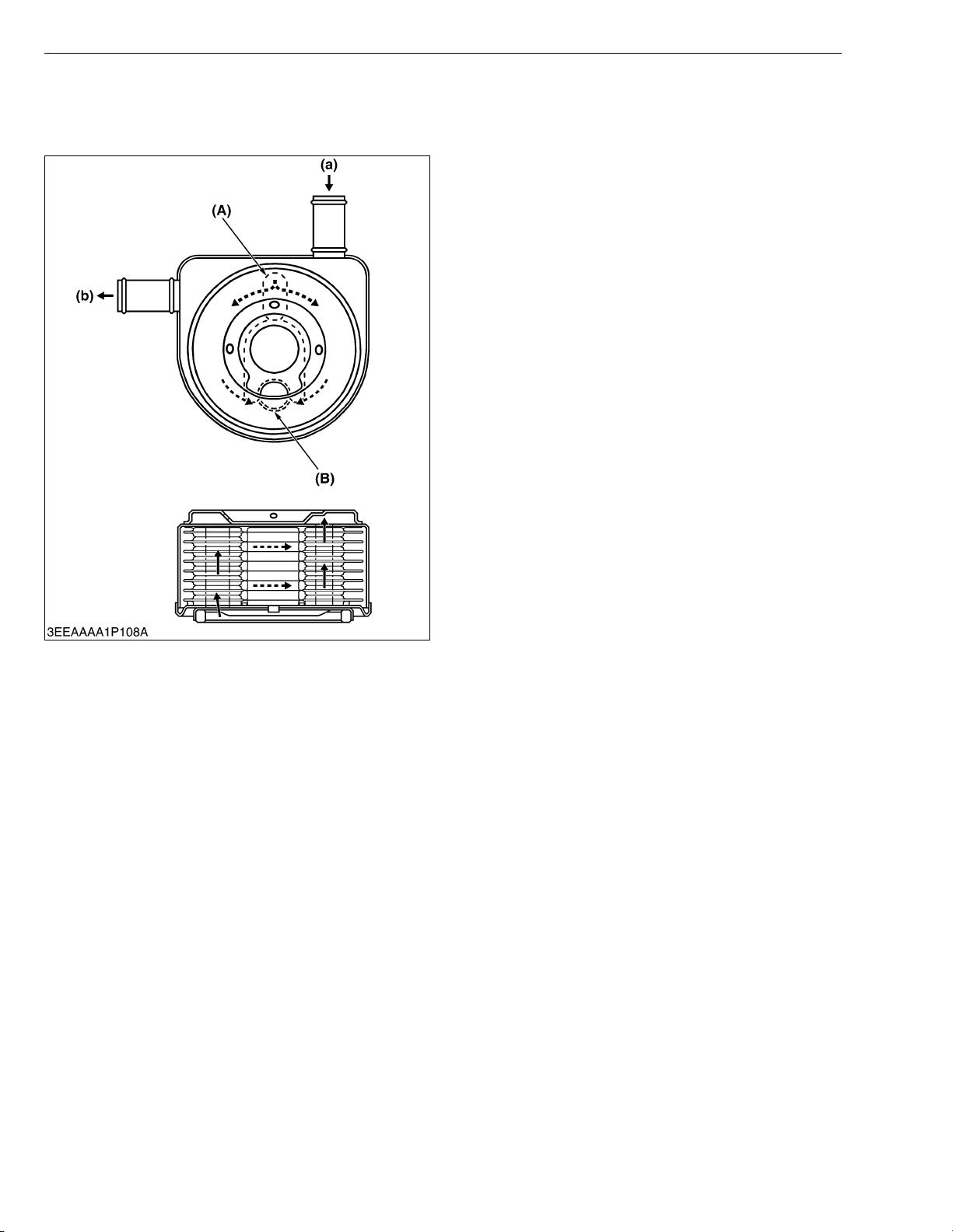
V3307-DI-T-E2B, WSM
KiSC issued 01, 2009 A
3. LUBRICATING SYSTEM
[1] OIL COOLER
ENGINE
The 07 series engine has a coolant-cooled oil cooler
that not only cools hot oil, but also warms the cool engine
oil shortly after start up.
As shown in the figure, the oil flows inside the
connected cooler plate, whereas coolant is kept
circulating outside the cooler plate, thereby cooling down
or warming the oil.
(A) Oil Inlet Port
(B) Oil Outlet Port
(a) Coolant Inlet Port
(b) Coolant Outlet Port
W10344770
M-8
Page 60
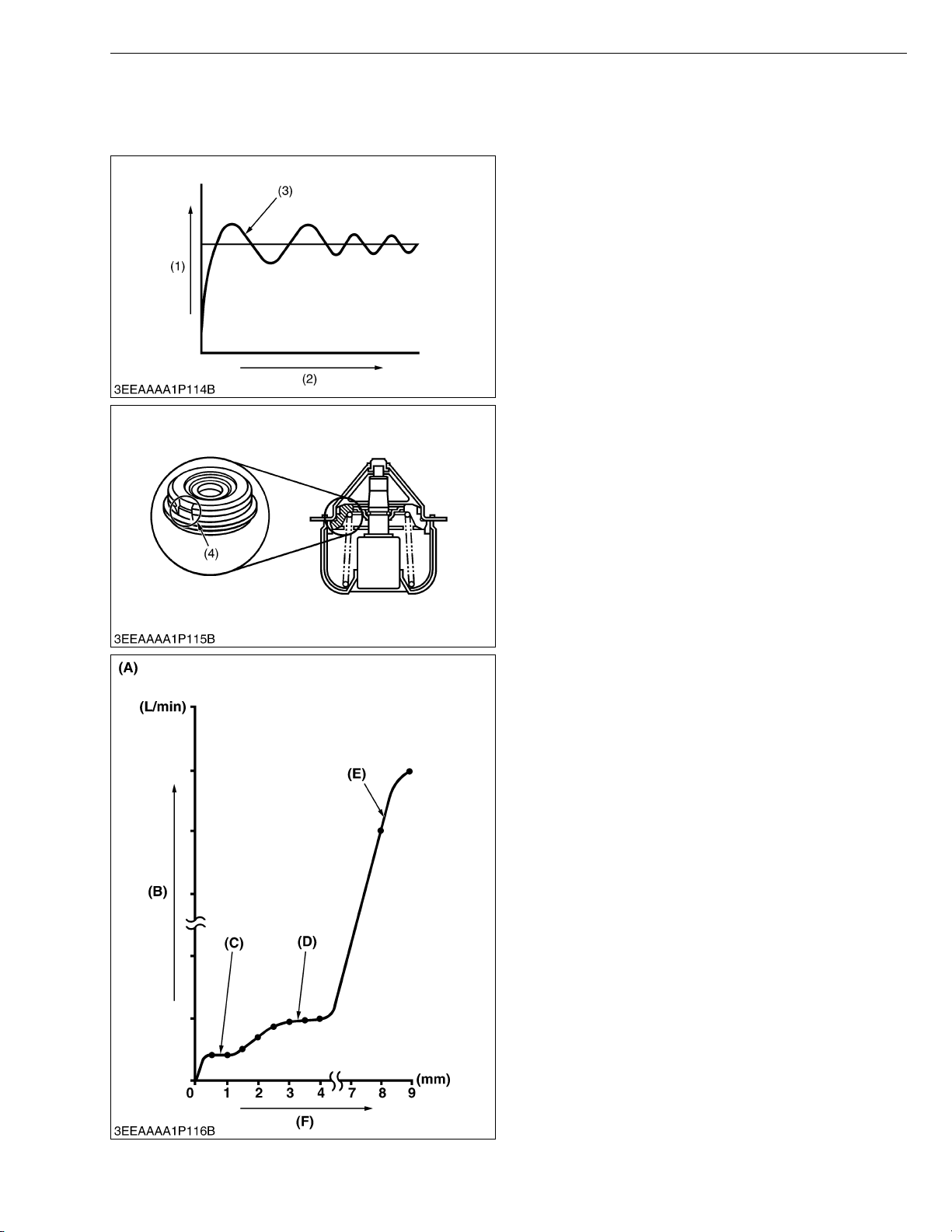
V3307-DI-T-E2B, WSM
KiSC issued 01, 2009 A
4. COOLING SYSTEM
[1] THERMOSTAT
ENGINE
Conventional thermostatically-controlled valves
(outlet water temperature control type) open against the
flow of coolant. In this design, the pressure (steam
pressure + water pump’s discharge pressure) affects the
open/close performance of such valve. In other words,
the valve may be delayed in opening at a preset opening
temperature opening suddenly, above the preset
temperature. This is called the overshoot phenomenon.
The overshoot problem invites the undershoot
phenomenon too. Too much water cooled by the radiator
flows through the water passage, which suddenly closes
the valve below the thermostat’s preset valve closing
temperature.
A repeated cycle of such overshoot (3) and
undershoot phenomena is called the water temperature
hunting. This hunting problem may adversely affect the
cooling system parts, and also the engine and its related
components.
To cope with this trouble, the 07 series engine is
equipped with the flow control thermostat. The valve has
a notch (4) to control the coolant flow-rate smoothly in
small steps.
(1) Coolant Temperature
(2) Time
(3) Overshoot
(4) Notch
(A) Valve Lift Versus Flow-rate
(B) Flow-rate
(C) At Short Valve Lift
(D) At Medium Valve Lift
(E) At High Valve Lift
(F) Valve Lift
W1013684
M-9
Page 61
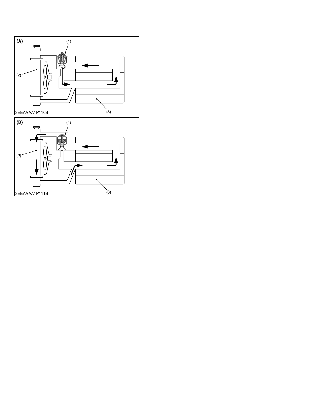
V3307-DI-T-E2B, WSM
KiSC issued 01, 2009 A
[2] BOTTOM BYPASS SYSTEM
ENGINE
Bottom bypass system is introduced in the 07 series
for improving the cooling performance of the radiator.
While the temperature of coolant in the engine is low,
the thermostat (1) is held closed and the coolant is
allowed to flow through the bypass pipe and to circulate
in the engine.
When the temperature exceeds the thermostat (1)
valve opening level, the thermostat (1) fully opens itself
to prevent the hot coolant from flowing through the
bypass into the engine.
In this way, the radiator can increase its cooling
performance.
(1) Thermostat
(2) Radiator
(3) Engine
(A) Bypass Opened
(B) Bypass Closed
W1013406
M-10
Page 62
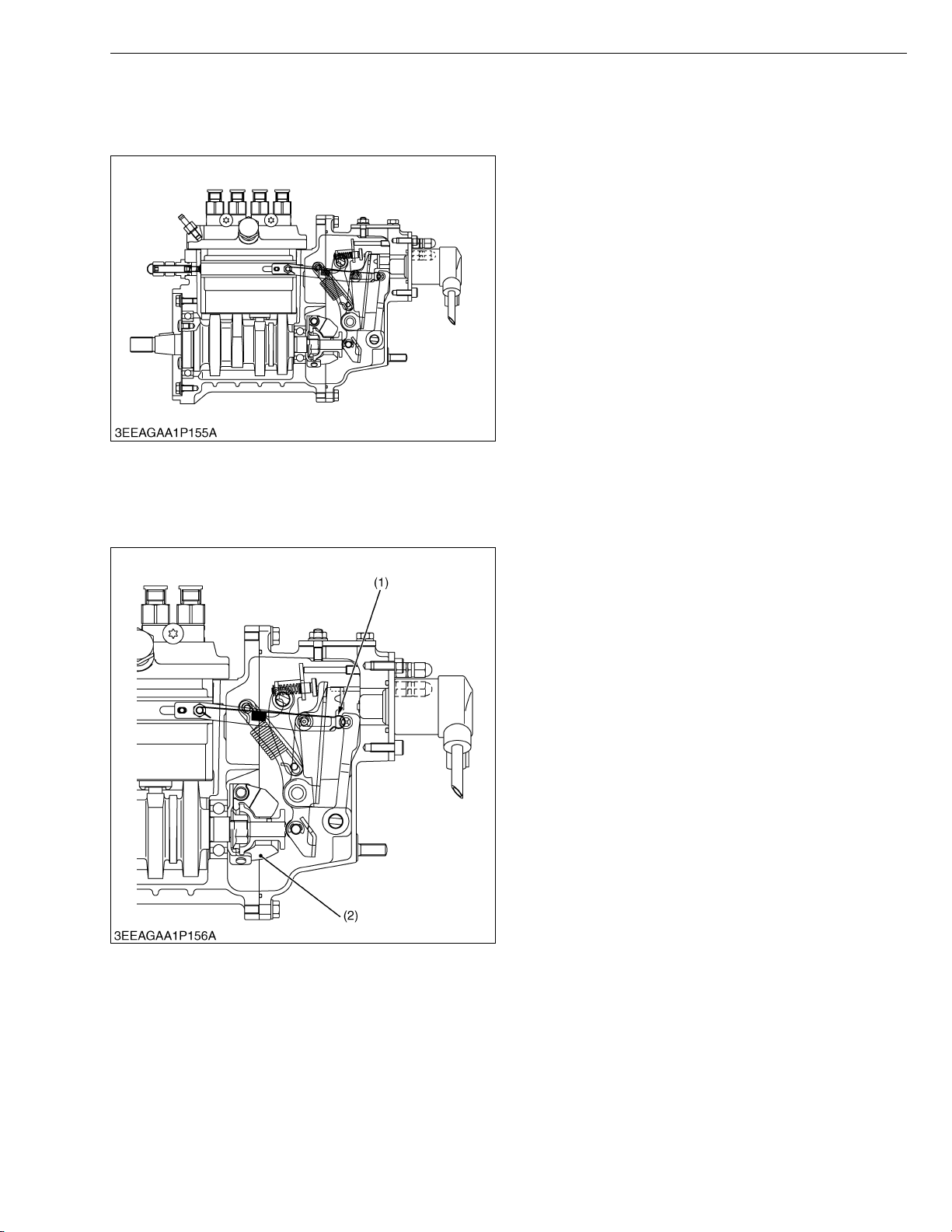
V3307-DI-T-E2B, WSM
KiSC issued 01, 2009 A
5. FUEL SYSTEM
[1] GOVERNOR
ENGINE
The engine employs the separated fuel injection
pump in combination with Kubota’s own small multifunction mechanical governor, which enables more
dependability.
It also employs the torque limiting mechanism to
control the maximum peak torque so that it complies with
the regulations of exhaust gas.
This mechanism maintains engine speed at a
constant level even under fluctuating loads, provides
stable idling and regulates maximum engine speed by
controlling the fuel injection rate.
This engine uses a mechanical governor that controls
the fuel injection rate at all speed ranges (from idling to
maximum speed) by utilizing the balance between the
flyweight’s centrifugal force and spring tension.
A governor shaft for monitoring engine speed is
independent of the injection pump shaft and rotates at
twice the speed of conventional types, providing better
response to load fluctuation and delivering greater
engine output.
W1013830
Q At Start
The stop solenoid (energized-to-run type) is powered
to release the stop lever.
As no centrifugal force is applied to flyweight (2), low
tension of start spring (1) permits control rack to move
the starting position, supplying the amount of fuel
required to start the engine.
(1) Start Spring (2) Flyweight
W1013967
M-11
Page 63
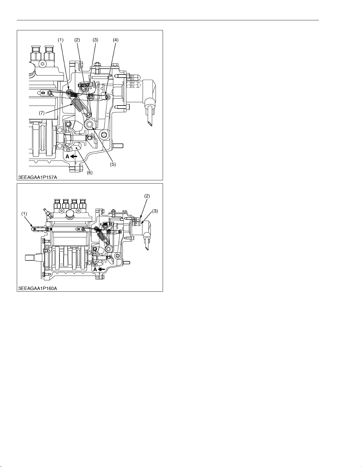
V3307-DI-T-E2B, WSM
KiSC issued 01, 2009 A
ENGINE
Q At Idling
Turn the speed control lever (2) clockwise to idle the
engine. It tensions the governor spring (7) to pull the fork
lever 2 (1).
When the fork lever 2 (1) is pulled, it moves the torque
spring pin (3) and the fork lever 1 (5) in the direction of
the arrow A to restrain the weight. In combination with
the start spring tension, it is balanced with the centrifugal
force of flywheel weight to keep idling.
(1) Fork Lever 2
(2) Speed Control Lever
(3) Spring Pin
(4) Start Spring
(5) Fork Lever 1
(6) Flyweight
(7) Governor Spring
W1014034
Q At rated speed with full load and overload
As the speed control lever is changed from the middle
speed to high speed, the governor spring tension
increases to compress the torque spring and move the
fork lever 1 in the direction of the arrow A.
The fork lever 2 moves until it reaches the output
limiting bolt (2) to keep rated rotation and rated output.
When the engine is overloaded, the engine rotating
speed decreases and the centrifugal force of flywheel
weight decreases. Then the torque spring moves the
fork lever 1 in the direction of arrow A.
The control rack moves in the direction that increases
fuel supply to increase the output. It is balanced with the
centrifugal force of the flywheel weight to produce lowspeed output (torque output).
(1) No-load Maximum Rotation
(2) Output Limiting Bolt
(3) Torque Limiting Bolt
W1014276
M-12
Page 64
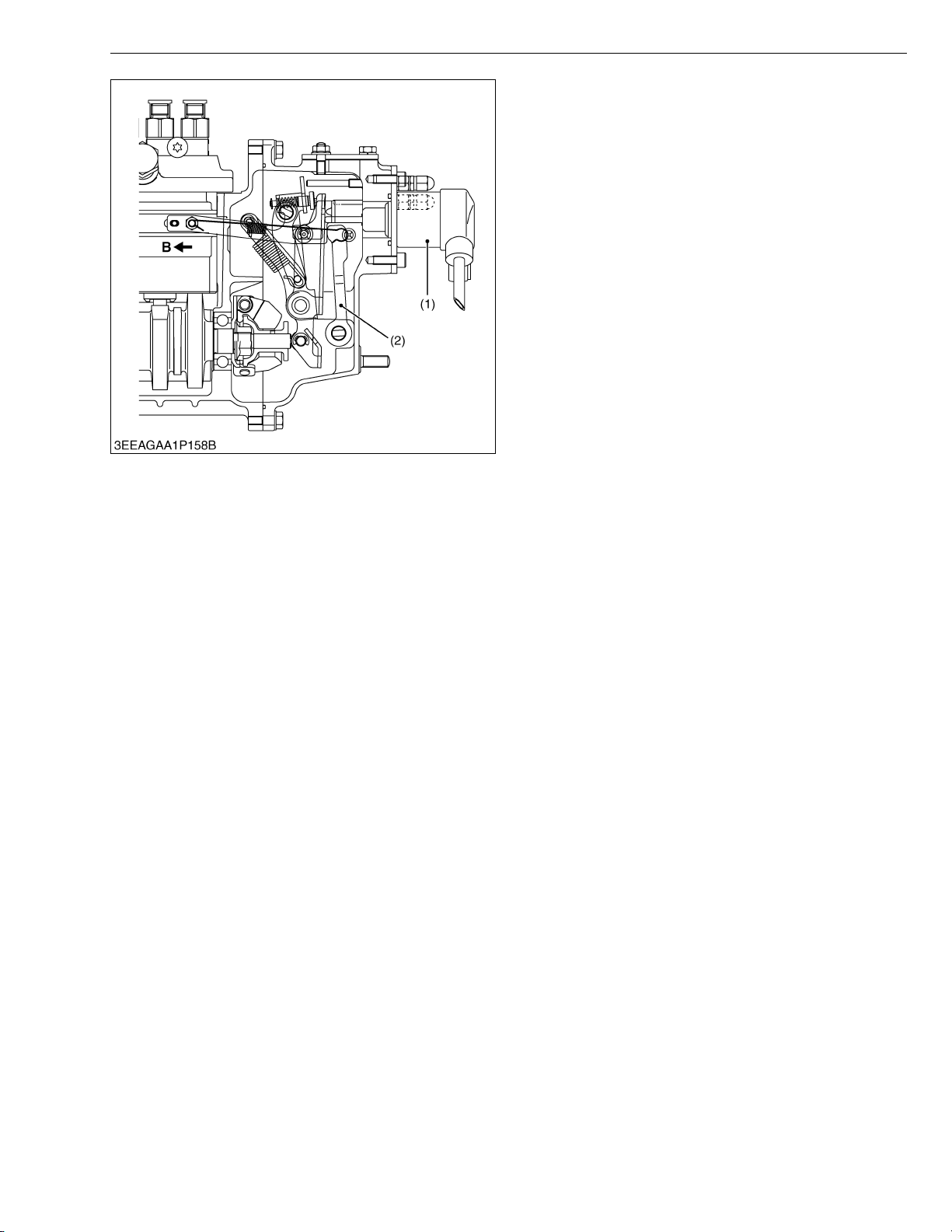
V3307-DI-T-E2B, WSM
KiSC issued 01, 2009 A
ENGINE
Q To stop engine
When the stop solenoid (1) is turned off, the spring
tension of the solenoid is released, the rod extrudes and
the stop lever moves the control rack in the direction of
the arrow B which stops the engine.
To stop the engine manually, move the external stop
lever to the left.
(1) Stop Solenoid (2) Stop Lever Shaft
W1014393
M-13
Page 65
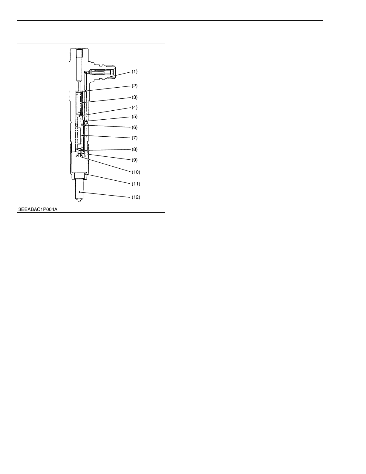
V3307-DI-T-E2B, WSM
KiSC issued 01, 2009 A
[2] 2 STAGE DI NOZZLE
ENGINE
Exhaust and noise regulations are becoming
increasingly strict, particularly in regard to the reduction
of NOx (nitrogen oxides) and particulates.
The two-spring nozzle holder has been developed to
reduce NOx (nitrogen oxides) and particulates from
direct injection diesel engine exhaust.
Q Features
The two-spring nozzle holder limits needle valve lift at
initial valve opening to throttle the injection quantity.
Main injection occurs when the in-line pressure has
increased sufficiently to move the needle valve through
its full lift.
This gives the following features.
• Improved engine stability at low and intermediate
speeds.
• Decreased engine hunting and surge.
• Decreased noise at idling.
• Decreased idling speed because of improved engine
stability.
• Stabilized fuel injection characteristics from the
injection pump and nozzle system, and easier
matching of governor characteristics to engine
demand.
(1) Nozzle Holder Body
(2) 1st Stage Injection Pressure
Adjusting Shim
(3) First Spring
(4) Pressure Pin
(5) Spring Seat
(6) 2nd Stage Injection Pressure
Adjusting Shim
(7) Second Spring
(8) Pre-lift Adjusting Spring Seat
(9) Chip-packing
(10) Max-lift Adjusting Washer
(11) Retaining Nut
(12) Nozzle
W1014568
M-14
Page 66
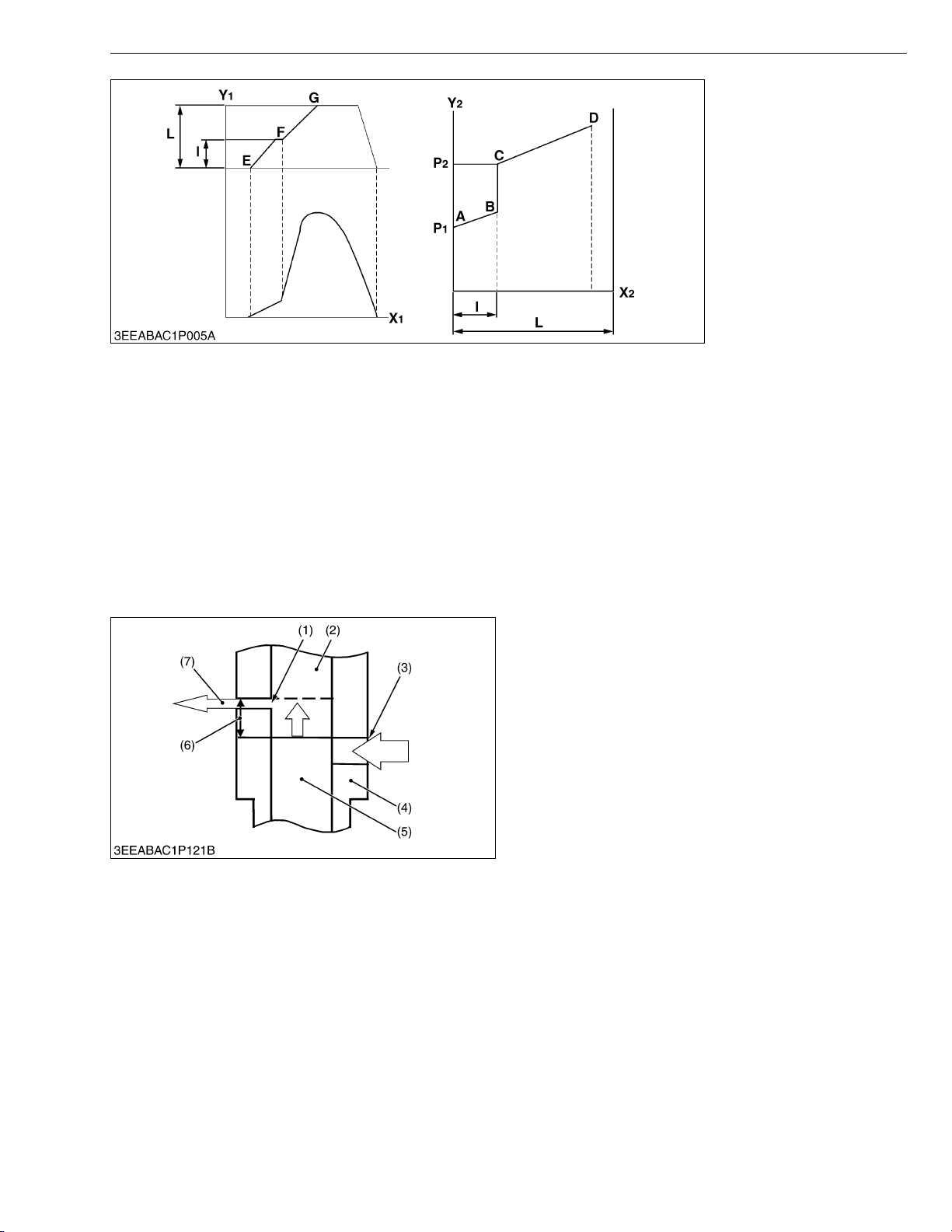
V3307-DI-T-E2B, WSM
KiSC issued 01, 2009 A
A-B : First Spring’s Set Force
B-C-D : Combined Force of
First and Second Springs
P1 : First Opening Pressure
P2 : Second Opening Pressure
L : Full Needle Valve Lift
l : Needle Valve Pre-lift
X1 : Cam Angle (°)
Y1 : Injection Rate (mm3/°)
X2 : Needle Valve Lift (mm)
Y2 : In-line Pressure
ENGINE
W1014795
Q First opening pressure
The force of the high pressure fuel delivered by the injection pump acts to push the needle valve up. When this
force exceeds the set force of the first spring, the nozzle’s needle valve pushes the first pushrod up and the valve
opens. (First opening pressure is represented by point E in the bottom left hand figure, and point A in the above
figure.)
Q Second opening pressure
When the first pushrod has been lifted through the pre-lift, it contacts the second pushrod. As the set force of the
second spring is acting on the second pushrod, the combined forces of both the first spring and the second spring then
act on the needle valve, which will not lift unless these forces are overcome.
When the high pressure fuel (i.e., in-line pressure) overcomes the combined forces of the first and second springs,
the needle valve is again lifted and main injection can begin. (Second opening pressure is represented by point F in
the bottom left hand figure and B-C in the above figure.)
[3] INJECTION PUMP WITH F.S.P.
The fuel injection pump with F.S.P. (Fine Spill Port)
mechanism is equipped with two functions: speed timer
function and injection rate control function.
The former function works like this. As the rpm is low,
the injection timing gets delayed. This helps cut down on
NOx and operating noise.
The latter function serves to keep down the initial
injection rate and keep up the later injection rate, which
cuts down on NOx and PM as well.
(1) Fine Spill Port (F.S.P.)
(2) Plunger Chamber
(3) Main Port
(4) Cylinder
(5) Plunger
(6) F.S.P. Stroke
(7) Leaking Fuel at Initial Fuel
Pressure-Feed Stage
W1014969
M-15
Page 67
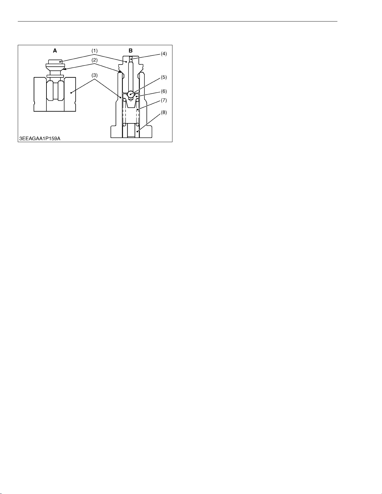
V3307-DI-T-E2B, WSM
KiSC issued 01, 2009 A
[4] CPV EQUIPPED DELIVERY VALVE
ENGINE
The Constant Pressure Valve (CPV) is a mechanism
that maintains uniform residual pressure in the high
pressure pipe. It stabilizes overall delivery quantity
characteristics and especially delivery quantity
characteristics at low speeds.
Q At high fuel pressure
The delivery valve (1), the steel ball (5) and the
snapper valve (6) are moved up together. The delivery
valve seat surface (2) opens when the fuel pressure
becomes more than the delivery valve set pressure.
Q At after injection
The delivery valve (1), the steel ball (5) and the
snapper valve (6) are moved down and the delivery valve
seat surface (2) closes. The steel ball still opens on the
way and the fuel returns to the injection pump side. The
steel ball (5) closes when the fuel pressure becomes less
than the snapper valve set pressure.
(1) Delivery Valve
(2) Seat Surface
(3) Valve Seat
(4) Orifice
(5) Steel Ball
(6) Snapper Valve
(7) Snapper Valve Spring
(8) Snapper Valve Seat
A : Current Delivery Valve
B : CPV Equipped Delivery
Valve
W1015816
M-16
Page 68
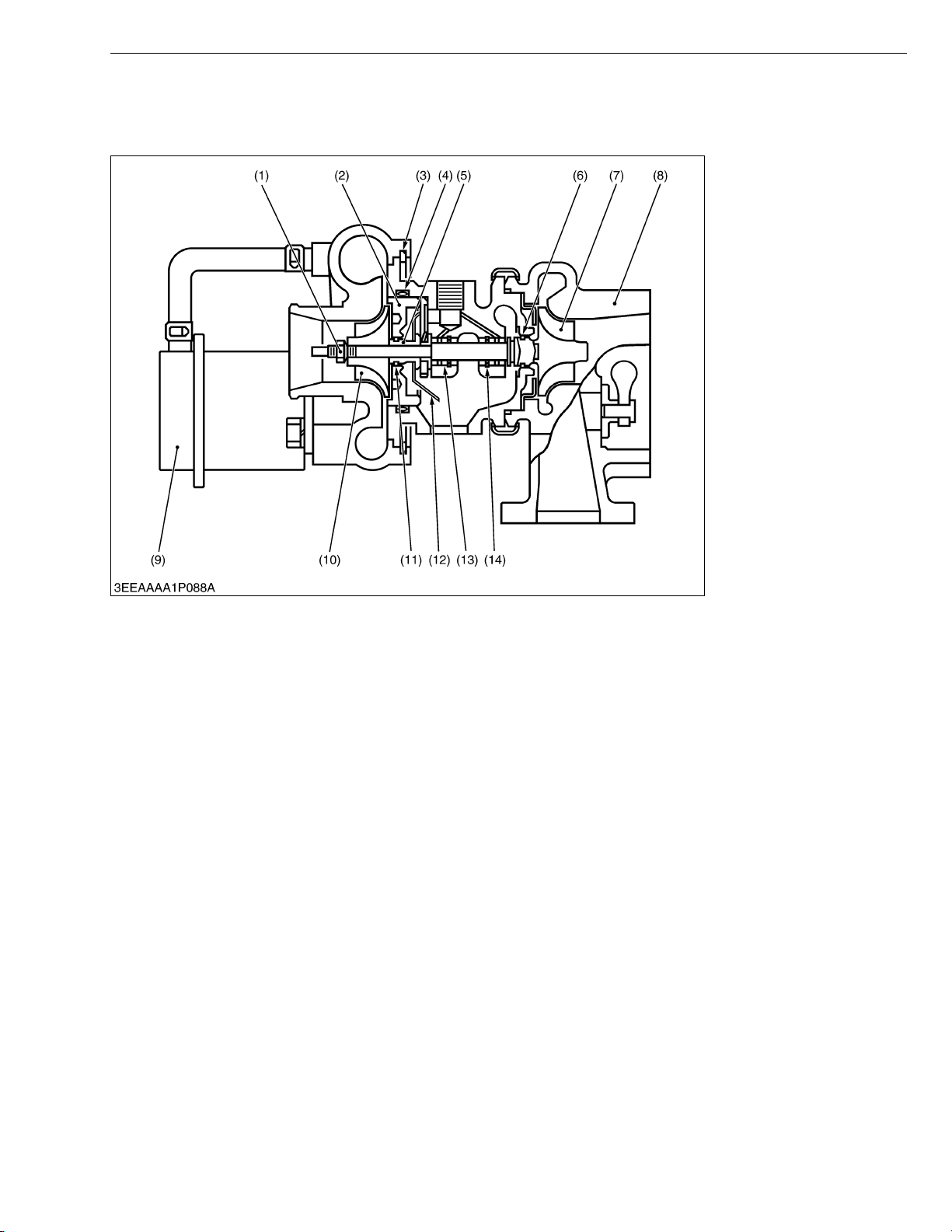
V3307-DI-T-E2B, WSM
KiSC issued 01, 2009 A
6. INTAKE AND EXHAUST SYSTEM
[1] TURBOCHARGER
ENGINE
(1) Lock Nut
(2) Thrust Bearing
(3) Snap Ring
(4) O-ring
(5) Thrust Sleeve
(6) Piston Ring
(7) Turbine Wheel
(8) Turbine Housing
(9) Actuator
(10) Compressor Wheel
(11) Piston Ring
(12) Oil Deflector
(13) Bearing
(14) Snap Ring
W10353780
A turbocharger consists basically of a centrifugal compressor mounted on a common shaft with a turbine driven by
exhaust gas. The compressor is usually located between the air cleaner and the intake manifold (or intercooler; if
equipped), while the turbine is located between the exhaust manifold and the muffler.
The prime job of the turbocharger is, by compressing the air, to force more air into the engine cylinders. This allows
the engine to efficiently burn more fuel, thereby producing more horsepower.
In applications where the boost pressure is relatively low, the turbocharger is capable of reducing the smoke
concentration, the concentration in the cylinder, fuel consumption, and deterioration in performance at elevated terrain
by increasing the amount of air into the engine cylinders.
In applications where the boost pressure is high, the turbocharger is capable of providing a large increase in engine
output by increasing the amount of air into the engine cylinders.
M-17
Page 69

SERVICING
KiSC issued 01, 2009 A
CONTENTS
1. TROUBLESHOOTING ......................................................................................S-1
2. SERVICING SPECIFICATIONS ......................................................................S-5
3. TIGHTENING TORQUES ..............................................................................S-12
[1] TIGHTENING TORQUES FOR GENERAL USE SCREWS, BOLTS
AND NUTS...............................................................................................S-12
[2] TIGHTENING TORQUES FOR SPECIAL USE SCREWS, BOLTS
AND NUTS...............................................................................................S-13
4. CHECKING, DISASSEMBLING AND SERVICING......................................S-15
[1] CHECKING AND ADJUSTING ...............................................................S-15
(1) Engine Body........................................................................................S-15
(2) Lubricating System .............................................................................S-17
(3) Cooling System ...................................................................................S-17
(4) Fuel System ........................................................................................S-20
(5) Electrical System ................................................................................S-23
(6) Turbocharger ......................................................................................S-27
[2] DISASSEMBLING AND ASSEMBLING..................................................S-28
(1) Draining Oil and Coolant .....................................................................S-28
(2) External Components .........................................................................S-28
(3) Cylinder Head and Valves ..................................................................S-31
(4) Thermostat ..........................................................................................S-35
(5) Injection Pump Unit .............................................................................S-36
(6) Water Pump and Oil Cooler ................................................................S-45
(7) Front Cover .........................................................................................S-46
(8) Flywheel and Timing Gears ................................................................S-47
(9) Piston and Connecting Rod ................................................................S-51
(10)Crankshaft and Crankcase .................................................................S-54
(11)Starter .................................................................................................S-56
(12)Alternator ............................................................................................S-56
[3] SERVICING ..............................................................................................S-59
(1) Cylinder Head and Valves ..................................................................S-59
(2) Timing Gears ......................................................................................S-65
(3) Piston and Connecting Rod ................................................................S-67
(4) Crankshaft...........................................................................................S-70
(5) Cylinder ...............................................................................................S-74
(6) Oil Pump .............................................................................................S-75
(7) Relief Valve .........................................................................................S-76
(8) Starter .................................................................................................S-76
(9) Alternator ............................................................................................S-78
Page 70
V3307-DI-T-E2B, WSM
KiSC issued 01, 2009 A
1. TROUBLESHOOTING
ENGINE
Symptom Probable Cause Solution
Engine Does Not
Start
Starter Does Not Run Battery discharged Charge G-18, 19
No fuel Replenish fuel G-11
Air in the fuel system Vent air G-11
Water in the fuel system Change fuel and
repair or replace fuel
system
Fuel hose clogged Clean or replace G-11, 27
Fuel filter clogged Replace G-13, 15
Excessively high viscosity of fuel or engine oil at
low temperature
Fuel with low cetane number Use specified fuel G-6
Fuel leak due to loose injection pipe retaining nut Tighten retaining nut S-31
Incorrect injection timing Adjust S-20
Fuel camshaft worn Replace S-41
Injection nozzle clogged Repair or replace S-22, 32
Injection pump malfunctioning Repair or replace S-21, 43
Seizure of crankshaft, camshaft, piston, cylinder
or bearing
Compression leak from cylinder Replace head
Improper valve timing Correct or replace
Piston ring and cylinder worn Replace S-52, 53,
Excessive valve clearance Adjust S-16
Stop solenoid malfunctioning Replace S-26
Starter malfunctioning Repair or replace S-25, 56,
Key switch malfunctioning Replace –
Wiring disconnected Connect –
Use specified fuel or
engine oil
Repair or replace –
gasket, tighten
cylinder head screw,
glow plug and nozzle
holder
timing gear
Reference
Page
–
G-6, 9
S-31 to 34
S-50
69, 74
76
W1034445
S-1
Page 71
V3307-DI-T-E2B, WSM
KiSC issued 01, 2009 A
ENGINE
Symptom Probable Cause Solution
Engine Revolution Is
Not Smooth
Fuel filter clogged or dirty Replace G-13, 15
Air cleaner clogged Clean or replace G-12, 24
Fuel leak due to loose injection pipe retaining nut Tighten retaining nut S-31
Injection pump malfunctioning Repair or replace S-21, 43
Incorrect nozzle opening pressure Repair or replace S-22, 32
Injection nozzle stuck or clogged Repair or replace S-22, 32
Governor malfunctioning Repair S-38, 39
Turbocharger bearing worn out Replace the
turbocharger
assembly
Turbocharger shaft bent Replace the
turbocharger
assembly
Turbocharger fin or other part damaged due to
foreign matters
Replace the
turbocharger
assembly
Either White or Blue
Exhaust Gas Is
Observed
Excessive engine oil Reduce to specified
level
Piston ring and cylinder worn or stuck Repair or replace S-52, 53,
Incorrect injection timing Adjust S-20
Oil Leak into Exhaust
Pipe or Suction Pipe
Waste oil pipe clogged or deformed Repair or replace S-29
Turbocharger’s piston ring seal faulty Replace the
turbocharger
assembly
Either Black or Dark
Gray Exhaust Gas Is
Observed
Overload Reduce the load –
Low grade fuel used Use specified fuel G-6
Fuel filter clogged Replace G-13, 15
Air cleaner clogged Clean or replace G-12, 24
Deficient nozzle injection Repair or replace
nozzle
Reference
Page
S-27, 29
S-27, 29
S-27, 29
G-7, 9
69, 74
S-29
S-22, 32
W1036076
S-2
Page 72
V3307-DI-T-E2B, WSM
KiSC issued 01, 2009 A
ENGINE
Symptom Probable Cause Solution
Reference
Page
Deficient Output Incorrect injection timing Adjust S-20
Engine’s moving parts seem to be seizing Repair or replace –
Injection pump malfunctioning Repair or replace S-21, 43
Deficient nozzle injection Repair or replace
S-22, 32
nozzle
Compression leak Check the
compression
S-15,
31 to 34
pressure and repair
Gas leak from exhaust system Repair or replace S-27, 29
Air leak from compressor discharge side Repair or replace S-27, 29
Air cleaner dirty or clogged Clean or replace G-12, 24
Compressor wheel turning heavily Replace the
S-27, 29
turbocharger
assembly
Excessive Lubricant
Oil Consumption
Piston ring’s gap facing the same direction Shift ring gap
direction
S-52, 53
Oil ring worn or stuck Replace S-52, 53,
69
Piston ring groove worn Replace piston S-52, 53,
69
Valve stem and valve guide worn Replace S-35, 61
Crankshaft bearing and crank pin bearing worn Replace S-52, 53,
70 to 72
Oil leaking due to defective seals or packing Replace –
Fuel Mixed into
Lubricant Oil
Injection pump’s plunger worn Repair or replace S-21, 43
Deficient nozzle injection Repair or replace
S-22, 32
nozzle
Injection pump broken Replace S-21, 43
Water Mixed into
Lubricant Oil
Head gasket defective Replace S-33, 34
Cylinder block or cylinder head flawed Replace S-60
Low Oil Pressure Engine oil insufficient Replenish G-7, 9
Oil strainer clogged Clean S-51
Relief valve stuck with dirt Clean S-46, 76
Relief valve spring weaken or broken Replace S-46, 76
Excessive oil clearance of crankshaft bearing Replace S-54, 72
Excessive oil clearance of crankpin bearing Replace S-52, 71
Excessive oil clearance of rocker arm Replace S-32, 63
Oil passage clogged Clean –
Different type of oil Use specified type of
G-6, 9
oil
Oil pump defective Replace S-17, 75
W1037777
S-3
Page 73
V3307-DI-T-E2B, WSM
KiSC issued 01, 2009 A
ENGINE
Symptom Probable Cause Solution
High Oil Pressure Different type of oil Use specified type of
Reference
Page
G-6, 9
oil
Relief valve defective Replace S-46, 76
Engine Overheated Engine oil insufficient Replenish G-7, 9
Fan belt broken or elongated Replace or adjust G-12, 15
Coolant insufficient Replenish G-8, 15
Radiator net and radiator fin clogged with dust Clean –
Inside of radiator corroded Clean or replace G-15
Coolant flow route corroded Clean or replace G-15
Radiator cap defective Replace S-18
Overload running Reduce the load –
Head gasket defective Replace S-33, 34
Incorrect injection timing Adjust S-20
Unsuitable fuel used Use specified fuel G-6
Battery Quickly
Discharged
Battery electrolyte insufficient Replenish distilled
water and charge
Fan belt slips Adjust belt tension or
G-18, 19
G-12, 15
replace
Wiring disconnected Connect –
Rectifier defective Replace S-26, 56
Alternator defective Replace S-26, 56
Battery defective Replace G-27,
S-23, 24
W1168623
S-4
Page 74
V3307-DI-T-E2B, WSM
KiSC issued 01, 2009 A
2. SERVICING SPECIFICATIONS
ENGINE BODY
Item Factory Specification Allowable Limit
Compression Pressure 3.92 MPa /
−1
250 min
40.0 kgf/cm
250 min
(rpm)
−1
(rpm)
2
/
569 psi /
−1
250 min
(rpm)
Variance Among Cylinders – 10 % or less
Valve Clearance (Cold) 0.13 to 0.17 mm
0.0052 to 0.0068 in.
Top Clearance 0.60 to 0.80 mm
0.024 to 0.031 in.
Cylinder Head Surface Flatness – 0.05 mm
Valve Recessing (Intake and Exhaust) 0.65 to 0.85 mm
0.026 to 0.033 in.
Valve Stem to Valve Guide (Intake and
Exhaust)
Clearance
0.055 to 0.085 mm
0.0022 to 0.0033 in.
2.90 MPa /
250 min
29.6 kgf/cm
250 min
421 psi /
250 min
–
–
0.002 in.
1.20 mm
0.0472 in.
0.10 mm
0.0039 in.
−1
−1
−1
ENGINE
(rpm)
2
/
(rpm)
(rpm)
Valve Stem
O.D.
6.960 to 6.975 mm
0.2741 to 0.2746 in.
Valve Guide
I.D.
7.030 to 7.045 mm
0.2768 to 0.2773 in.
Valve Face (Intake and Exhaust) Angle 0.79 rad
(45 °)
Valve Seat (Intake and Exhaust) Angle
0.79 rad
(45 °)
Width
3.3 to 3.6 mm
0.13 to 0.14 in.
Intake Valve Timing Open
0.24 rad (14 °)
before T.D.C.
Close
0.70 rad (40 °)
after B.D.C.
Exhaust Valve Timing Open
0.87 rad (50 °)
before B.D.C.
Close
0.24 rad (14 °)
after T.D.C.
Valve Spring (Intake and Exhaust) Tilt
–
–
–
–
–
–
–
–
–
–
1.0 mm
0.039 in.
Free Length
S-5
35.1 to 35.6 mm
1.39 to 1.40 in.
34.6 mm
1.36 in.
W1185533
Page 75

V3307-DI-T-E2B, WSM
KiSC issued 01, 2009 A
ENGINE BODY (Continued)
Item Factory Specification Allowable Limit
Valve Spring (Intake and Exhaust) Setting Load /
Setting Length
Rocker Arm Shaft to Rocker Arm
Oil Clearance
63.5 N / 31.5 mm
6.48 kgf / 31.5 mm
14.3 lbf / 1.24 in.
0.016 to 0.045 mm
0.00063 to 0.0017 in.
ENGINE
45.9 N /
31.5 mm
4.68 kgf / 31.5 mm
10.3 lbf /
1.24 in.
0.15 mm
0.0059 in.
Rocker Arm Shaft
O.D.
14.973 to 14.984 mm
–
0.58949 to 0.58992 in.
Rocker Arm
I.D.
15.000 to 15.018 mm
–
0.59056 to 0.59125 in.
Valve Bridge Arm and Valve Bridge Shaft
Valve Bridge Shaft
Oil Clearance
O.D.
0.018 to 0.042 mm
0.00071 to 0.0016 in.
9.023 to 9.032 mm
0.15 mm
0.0059 in.
–
0.3553 to 0.3555 in.
Valve Bridge Arm
I.D.
9.050 to 9.065 mm
–
0.3563 to 0.3568 in.
Push Rod Alignment – 0.25 mm
0.0098 in.
Tappet to Tappet Bore
Tappet
Oil Clearance
O.D.
0.020 to 0.050 mm
0.00079 to 0.0019 in.
9.965 to 9.980 mm
0.07 mm
0.003 in.
–
0.3924 to 0.3929 in.
Tappet Bore
I.D.
10.000 to 10.015 mm
–
0.39370 to 0.39429 in.
Timing Gear
Crank Gear to Cam Gear
Backlash
0.0410 to 0.139 mm
0.00162 to 0.00547 in.
0.22 mm
0.0087 in.
Cam Gear to Idle Gear
Idle Gear to Injection Pump Gear
Idle Gear Side Clearance 0.15 to 0.25 mm
Idle Gear Shaft to Idle Gear Bushing
Idle Gear Shaft
Idle Gear Bushing
Backlash
Backlash
Oil Clearance
O.D.
I.D.
S-6
0.0410 to 0.134 mm
0.00162 to 0.00527 in.
0.0410 to 0.134 mm
0.00162 to 0.00527 in.
0.0059 to 0.0098 in.
0.050 to 0.091 mm
0.0020 to 0.0036 in.
34.959 to 34.975 mm
1.3764 to 1.3769 in.
35.025 to 35.050 mm
1.3790 to 1.3799 in.
0.22 mm
0.0087 in.
0.22 mm
0.0087 in.
0.90 mm
0.035 in.
0.10 mm
0.0039 in.
–
–
W1041245
Page 76

V3307-DI-T-E2B, WSM
KiSC issued 01, 2009 A
ENGINE BODY (Continued)
Item Factory Specification Allowable Limit
Camshaft Side Clearance – 0.10 mm
0.0039 in.
Camshaft Alignment – 0.01 mm
0.0004 in.
Cam Height Intake
37.50 mm
1.476 in.
37.00 mm
1.457 in.
ENGINE
Exhaust
37.90 mm
1.492 in.
Camshaft
Oil Clearance
0.050 to 0.091 mm
0.0020 to 0.0035 in.
Camshaft Journal 1
O.D.
34.934 to 34.950 mm
1.3754 to 1.3759 in.
Cylinder Block Bore 1
I.D.
35.000 to 35.025 mm
1.3780 to 1.3789 in.
Camshaft Journal 2
O.D.
43.934 to 43.950 mm
1.7297 to 1.7303 in.
Cylinder Block Bore 2
I.D.
44.000 to 44.025 mm
1.7323 to 1.7332 in.
Piston Pin Bore I.D. 28.000 to 28.013 mm
1.1024 to 1.1028 in.
Piston Pin to Small End Bushing
Oil Clearance
0.020 to 0.040 mm
0.00079 to 0.0015 in.
Piston Pin
O.D.
28.006 to 28.011 mm
1.1026 to 1.1027 in.
37.40 mm
1.472 in.
0.15 mm
0.0059 in.
–
–
–
–
28.05 mm
1.104 in.
0.15 mm
0.0059 in.
–
Small End Bushing
I.D.
28.031 to 28.046 mm
–
1.1036 to 1.1041 in.
Connecting Rod Alignment – 0.05 mm
0.002 in.
Piston Ring Gap Top Ring
Second Ring
Oil Ring
0.25 to 0.40 mm
0.0099 to 0.015 in.
0.30 to 0.45 mm
0.012 to 0.017 in.
0.25 to 0.45 mm
0.0099 to 0.017 in.
1.25 mm
0.0492 in.
1.25 mm
0.0492 in.
1.25 mm
0.0492 in.
W1042752
S-7
Page 77
V3307-DI-T-E2B, WSM
KiSC issued 01, 2009 A
ENGINE BODY (Continued)
Piston Ring to Piston Ring Groove
Top Ring
ENGINE
Item Factory Specification Allowable Limit
Clearance
0.050 to 0.090 mm
0.0020 to 0.0035 in.
0.15 mm
0.0059 in.
Second Ring
Oil Ring
Clearance
Clearance
Crankshaft Side Clearance 0.15 to 0.35 mm
0.090 to 0.12 mm
0.0035 to 0.0047 in.
0.020 to 0.060 mm
0.00079 to 0.0023 in.
0.0059 to 0.013 in.
0.20 mm
0.0079 in.
0.15 mm
0.0059 in.
0.50 mm
0.020 in.
Crankshaft Alignment – 0.02 mm
0.0008 in.
Crank Pin to Crank Pin Bearing
Crank Pin
Oil Clearance
O.D.
0.017 to 0.048 mm
0.00067 to 0.0018 in.
49.980 to 49.991 mm
0.20 mm
0.0079 in.
–
1.9678 to 1.9681 in.
Crankshaft Journal to Crankshaft Bearing
Crankshaft Journal
Oil Clearance
O.D.
0.030 to 0.073 mm
0.0012 to 0.0028 in.
79.977 to 79.990 mm
0.20 mm
0.0079 in.
–
3.1487 to 3.1492 in.
Cylinder Bore I.D. 94.000 to 94.022 mm
3.7008 to 3.7016 in.
Cylinder Bore (Oversize) I.D. 94.500 to 94.522 mm
3.7205 to 3.7213 in.
94.15 mm
3.707 in.
94.65 mm
3.726 in.
W10138740
S-8
Page 78
V3307-DI-T-E2B, WSM
KiSC issued 01, 2009 A
LUBRICATING SYSTEM
Item Factory Specification Allowable Limit
Engine Oil Pressure At Idle Speed
ENGINE
–
49 kPa
0.50 kgf/cm
2
7.1 psi
At Rated Speed
197 to 392 kPa
2.00 to 4.00 kgf/cm
28.5 to 56.8 psi
Engine Oil Pressure Switch Working Pressure 40 to 58 kPa
0.40 to 0.60 kgf/cm
5.7 to 8.5 psi
Inner Rotor to Outer Rotor Clearance 0.030 to 0.090 mm
0.0012 to 0.0035 in.
Outer Rotor to Pump Body Clearance 0.100 to 0.184 mm
0.00394 to 0.00724 in.
Rotor to Cover Clearance 0.025 to 0.075 mm
0.00099 to 0.0029 in.
Relief Valve Spring Free
Length
Working Pressure
60.0 to 60.5 mm
2.37 to 2.38 in
294 kPa
3.00 kgf/cm
2
42.7 psi
COOLING SYSTEM
Fan Belt Tension 10.0 to 12.0 mm / 98 N
0.394 to 0.472 in. / 98 N
(10 kgf, 22 lbf)
Radiator Cap Pressure Falling
Time
10 seconds or more
88 → 59 kPa
0.90 → 0.60 kgf/cm
13 → 8.5 psi
Radiator Water Leakage
Tes t P r e s su re
Thermostat Valve Opening
Temperature
No leak at specified
pressure
74.5 to 78.5 °C
166.1 to 173.3 °F
2
147 kPa
1.50 kgf/cm
2
21.3 psi
2
–
0.30 mm
0.012 in.
0.30 mm
0.012 in.
0.225 mm
0.00886 in.
55.0 mm
2.17 in.
–
W10139730
–
–
2
–
–
Valve Opening
Temperature
(Opened
Completely)
S-9
90 °C
194 °F
–
W10135990
Page 79

V3307-DI-T-E2B, WSM
KiSC issued 01, 2009 A
FUEL SYSTEM
Item Factory Specification Allowable Limit
Injection Timing V3307-DI-T-E2B 0.00436 rad before
–
T.D.C. to 0.0218 rad
after T.D.C.
(0.250 ° before T.D.C. to
1.25 ° after T.D.C.)
Pump Element Fuel Tightness – 18.63 MPa
190.0 kgf/cm
2702 psi
Delivery Valve Fuel Tightness 10 seconds
18.63 → 17.65 MPa
190.0 → 180.0 kgf/cm
2702 → 2560 psi
2
5 seconds
18.63 → 17.65 MPa
190.0 →
180.0 kgf/cm
2702 → 2560 psi
Fuel Injection Nozzle Injection Pressure
(1st stage)
18.64 to 19.61 MPa
190.0 to 200.0 kgf/cm
2
–
2703 to 2844 psi
ENGINE
2
2
Injection Pressure
(2nd stage)
Valve Seat
Tightness
22.56 to 23.53 MPa
230.0 to 240.0 kgf/cm
2
3272 to 3413 psi
When the pressure is
16.67 MPa
(170.0 kgf/cm
2
, 2418
psi), the valve seat must
be fuel tightness.
–
–
W10139730
S-10
Page 80

V3307-DI-T-E2B, WSM
KiSC issued 01, 2009 A
ELECTRICAL SYSTEM
Item Factory Specification Allowable Limit
Glow Plug Resistance Approx. 0.95 Ω –
Starter
Commutator
O.D.
32.0 mm
31.4 mm
1.26 in.
ENGINE
1.24 in.
Mica
Brush
Brush Holder - Holder Support
Commutator - Armature Coil Core
Commutator - Segment
Field Coil Lead - Brush
Field Coil Brush - Yoke
Alternator
No-load Voltage
Stator
Rotor
Undercut
Length
Resistance
Resistance
Resistance
Resistance
Resistance
Output Voltage
Resistance
Resistance
0.50 mm
0.020 in.
18.0 mm
0.709 in.
Infinity
Infinity
0 Ω
0 Ω
Infinity
13.8 to 14.8 V at
25 °C (77 °F),
4000 min
-1
(rpm)
Less than 1.0 Ω
2.8 to 3.3 Ω
0.20 mm
0.0079 in.
11.0 mm
0.433 in.
–
–
–
–
–
–
–
–
Slip Ring
Brush
O.D.
Length
22.7 mm
0.894 in.
18.5 mm
0.728 in.
22.1 mm
0.870 in.
5.0 mm
0.20 in.
W1173869
S-11
Page 81

V3307-DI-T-E2B, WSM
KiSC issued 01, 2009 A
ENGINE
3. TIGHTENING TORQUES
Screws, bolts and nuts must be tightened to the specified torque using a torque wrench, several screws, bolts and
nuts such as those used on the cylinder head must be tightened in proper sequence and the proper torque.
[1] TIGHTENING TORQUES FOR GENERAL USE SCREWS, BOLTS AND
NUTS
When the tightening torques are not specified, tighten the screws, bolts and nuts according to the table below.
Grade
Nominal Unit
Diameter
M6 7.9 to 9.3 0.80 to 0.95 5.8 to 6.8 9.81 to 11.2 1.00 to 1.15 7.24 to 8.31
M8 18 to 20 1.8 to 2.1 13 to 15 24 to 27 2.4 to 2.8 18 to 20
M10 40 to 45 4.0 to 4.6 29 to 33 49 to 55 5.0 to 5.7 37 to 41
M12 63 to 72 6.4 to 7.4 47 to 53 78 to 90 7.9 to 9.2 58 to 66
Screw and bolt material grades are shown by numbers punched on the screw and bolt heads. Prior to
tightening, be sure to check out the numbers as shown below.
Punched number Screw and bolt material grade
None or 4 Standard screw and bolt SS41, S20C
7 Special screw and bolt S43C, S48C (Refined)
Standard Screw and Bolt
N·m kgf·m lbf·ft N·m kgf·m lbf·ft
Special Screw and Bolt
W10371750
W1012705
S-12
Page 82
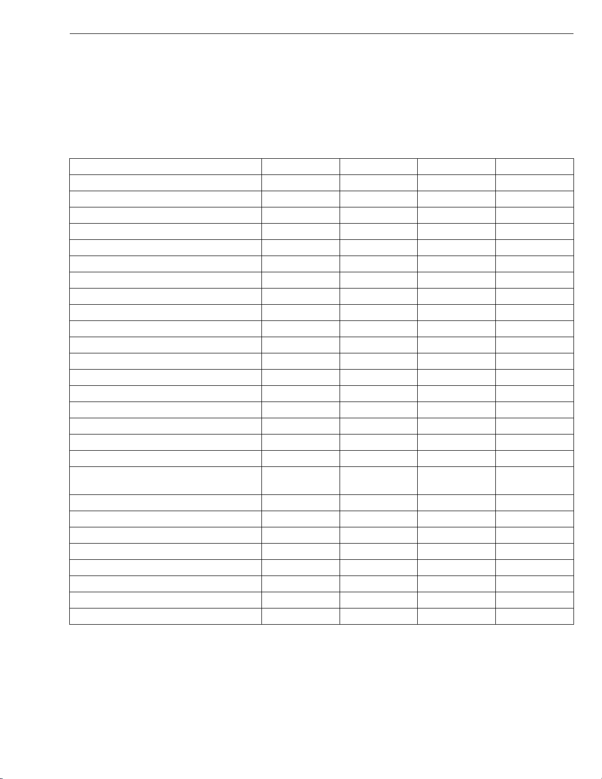
V3307-DI-T-E2B, WSM
KiSC issued 01, 2009 A
ENGINE
[2] TIGHTENING TORQUES FOR SPECIAL USE SCREWS, BOLTS AND
NUTS
NOTEQ
• For “*” marked screws, bolts and nuts on the table, apply engine oil to their threads and seats before
tightening.
• The letter “M” in Size x Pitch means that the screw, bolt or nut dimension stands for metric. The size is
the nominal outside diameter in mm of the threads. The pitch is the nominal distance in mm between two
threads.
Item Size x Pitch N·m kgf·m lbf·ft
Glow lead mounting nut M4 x 0.7 0.98 to 1.7 0.10 to 0.18 0.73 to 1.3
Glow plug M8 x 1.0 7.7 to 9.3 0.78 to 0.95 5.7 to 6.8
Cylinder head cover screw M6 x 1.0 9.81 to 11.2 1.00 to 1.15 7.24 to 8.31
Injection pipe retaining nut M12 x 1.5 23 to 36 2.3 to 3.7 17 to 26
Oil switch taper screw R 1/8 15 to 19 1.5 to 2.0 11 to 14
Injection pump unit mounting nut M8 x 1.25 18 to 20 1.8 to 2.1 13 to 15
Drain plug M22 x 1.5 45 to 53 4.5 to 5.5 33 to 39
Oil pipe 1 mounting screw M10 x 1.25 16 to 19 1.6 to 2.0 12 to 14
Thermo valve R 3/8 30 to 39 3.0 to 4.0 22 to 28
Nozzle holder clamp screw M8 x 1.25 24 to 27 2.4 to 2.8 18 to 20
Overflow pipe assembly retaining screw M6 x 1.0 9.81 to 11.2 1.00 to 1.15 7.24 to 8.31
*Lubricating oil pipe mounting screw M10 x 1.25 16 to 19 1.6 to 2.0 12 to 14
Governor housing mounting screw M6 x 1.0 9.81 to 11.2 1.00 to 1.15 7.24 to 8.31
Lock nut M5 x 0.8 2.9 to 4.0 0.29 to 0.41 2.1 to 2.9
Injection pump assembly mounting screw M8 x 1.25 24 to 27 2.4 to 2.8 18 to 20
Injection pump assembly mounting nut M8 x 1.25 18 to 20 1.8 to 2.1 13 to 15
Governor weight mounting nut M12 x 1.25 63 to 72 6.4 to 7.4 47 to 53
Fuel camshaft stopper mounting screw M6 x 1.0 9.81 to 11.2 1.00 to 1.15 7.24 to 8.31
Fuel camshaft bearing stopper mounting
screw
*Crankshaft screw M16 x 1.5 255 to 274 26.0 to 28.0 188 to 202
Relief valve retaining screw M22 x 1.5 69 to 78 7.0 to 8.0 51 to 57
*Flywheel screw M12 x 1.25 98.1 to 107 10.0 to 11.0 72.4 to 79.5
Camshaft set screw M8 x 1.25 24 to 27 2.4 to 2.8 18 to 20
Balancer shaft set screw M8 x 1.25 24 to 27 2.4 to 2.8 18 to 20
Starter’s terminal B mounting nut M8 x 1.25 9.8 to 11 1.0 to 1.2 7.3 to 8.6
Alternator pulley nut M24 58.4 to 78.9 5.95 to 8.05 43.1 to 58.2
Oil pump cover screw M6 7.9 to 9.3 0.80 to 0.95 5.8 to 6.8
M6 x 1.0 3.9 to 4.2 0.39 to 0.43 2.9 to 3.1
W1013236
S-13
Page 83
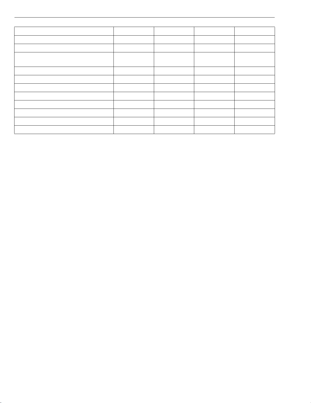
V3307-DI-T-E2B, WSM
KiSC issued 01, 2009 A
ENGINE
Item Size x Pitch N·m kgf·m lbf·ft
Rocker arm bracket screw M10 x 1.25 49 to 55 5.0 to 5.7 37 to 41
*Cylinder head mounting screw M14 x 1.5 187 to 196 19.0 to 20.0 138 to 144
Injection pump gear mounting nut
(left-handed screw)
M16 x 1.5 -LH 138 to 158 14.0 to 16.0 102 to 115
Oil cooler joint screw M20 x 1.5 40 to 44 4.0 to 4.5 29 to 32
Front cover mounting screw (7T) M8 x 1.25 24 to 27 2.4 to 2.8 18 to 20
Front cover mounting screw (10T) M8 x 1.25 30 to 34 3.0 to 3.5 22 to 25
Flywheel housing mounting screw (9T) M12 x 1.25 103 to 117 10.5 to 12.0 76.0 to 86.7
Idle gear mounting screw (10T) M8 x 1.25 30 to 34 3.0 to 3.5 22 to 25
*Connecting rod screw M9 x 1.0 69 to 73 7.0 to 7.5 51 to 54
*Crankcase 2 mounting screw M14 x 1.5 138 to 147 14.0 to 15.0 102 to 108
Crankcase 2 flange screw (9T) M10 x 1.25 59 to 63 6.0 to 6.7 44 to 47
W1335256
S-14
Page 84
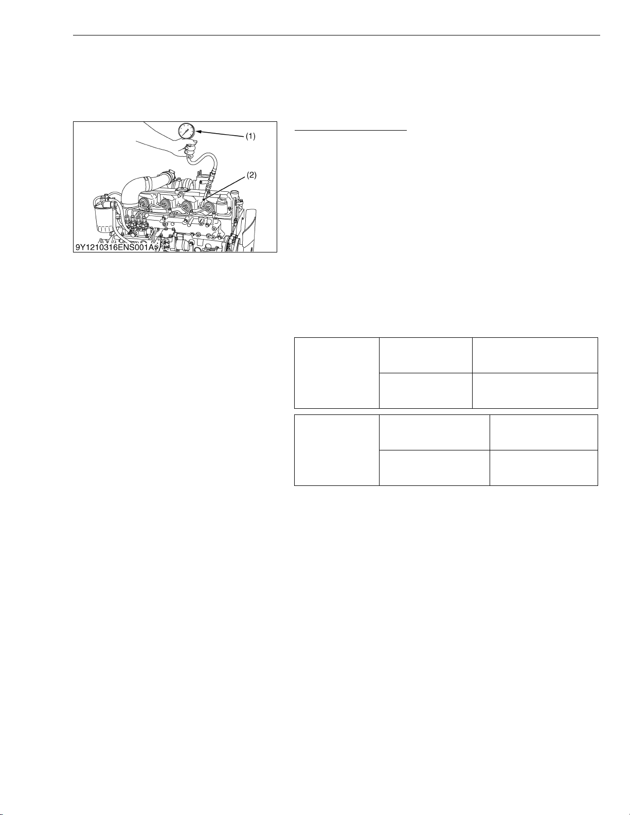
V3307-DI-T-E2B, WSM
KiSC issued 01, 2009 A
4. CHECKING, DISASSEMBLING AND SERVICING
[1] CHECKING AND ADJUSTING
(1) Engine Body
Compression Pressure
1. After warming up the engine, shut it down and remove the air
cleaner, the muffler, breather tube, glow lead and all glow plugs.
2. Install a compression tester (1) (Code No: 07909-30208) and
glow plug adaptor (2) to glow plug hole. (Refer to “5. SPECIAL
TOOLS” at “GENERAL” Section.)
3. After making sure that the stop lever is set at the stop position
(Non-injection), run the engine at 200 to 300 min
starter.
4. Read the maximum pressure. Measure the pressure more than
twice.
NOTEQ
• Check the compression pressure with the specified valve
clearance.
• Always use a fully charged battery for performing this test.
• Variances in cylinder compression values should be under
10 %.
Compression
pressure
Factory spec.
Allowable limit
3.92 MPa / 250 min
40.0 kgf/cm
569 psi / 250 min
2.90 MPa / 250 min
29.6 kgf/cm
421 psi / 250 min
2
/ 250 min-1 (rpm)
2
/ 250 min-1 (rpm)
ENGINE
−1
(rpm) with the
-1
(rpm)
-1
(rpm)
-1
(rpm)
-1
(rpm)
Glow lead mounting nut
Tightening torque
Glow plug
(1) Compression Tester (2) Glow Plug Adaptor
0.98 to 1.7 N·m
0.10 to 0.18 kgf·m
0.73 to 1.3 lbf·ft
7.7 to 9.3 N·m
0.78 to 0.95 kgf·m
5.7 to 6.8 lbf·ft
W1048776
S-15
Page 85
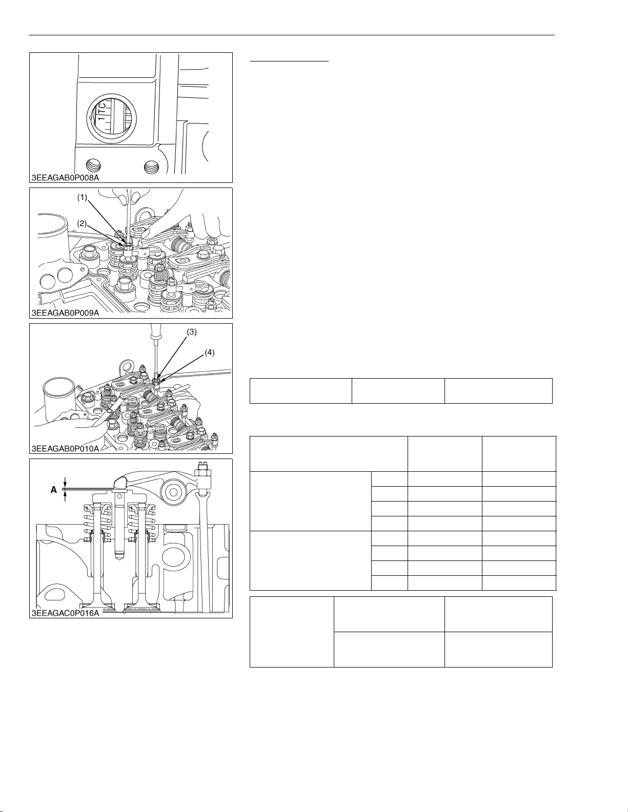
V3307-DI-T-E2B, WSM
KiSC issued 01, 2009 A
ENGINE
Valve Clearance
IMPORTANTQ
• Valve clearance must be checked and adjusted when engine
is cold.
1. Remove the high pressure pipes, glow lead, glow plugs and the
cylinder head cover.
2. Align the 1TC mark of flywheel and the convex of flywheel
housing timing windows so that the first piston (front cover side)
comes to the compression top dead center.
[Adjustable type of valve bridge arm]
3. Before adjusting the valve clearance, adjust the valve bridge arm
evenly to the valve stem.
4. Loosen the lock nut (2) of adjusting screw (1) and adjust with
screw.
5. Slightly push the rocker arm with your fingers and screw in the
adjusting screw (1) slowly until you feel the screw touch the top
of valve stem, then tighten the lock nut (2).
6. Loosen the lock nut (4) of adjusting screw (3) (push rod side) and
insert the feeler gauge between the rocker arm and the head of
valve bridge arm. Set the adjusting screw (3) to the specified
value, then tighten the lock nut.
[Adjustment unnecessary type of valve bridge arm]
3. Loosen the lock nut (4) of adjusting screw (3) (push rod side) and
insert the feeler gauge between the rocker arm and the head of
valve bridge arm. Set the adjusting screw (3) to the specified
value, then tighten the lock nut.
Valve clearance A Factory spec.
0.13 to 0.17 mm
0.0052 to 0.0066 in.
NOTEQ
• After adjusting, tighten the lock nut (4) securely.
Valve arrangement
Adjustment cylinder
Location of piston
When No.1 piston is at
compression top dead center
When No.1 piston is at
overlap position
Cylinder head cover screw
Tightening torque
Injection pipe retaining nut
(1) Adjusting Screw
(2) Lock Nut
(3) Adjusting Screw
(4) Lock Nut
1st ,,
2nd ,
3rd ,
4th
1st
2nd ,
3rd ,
4th ,,
A : Valve Clearance
IN. EX.
9.81 to 11.2 N·m
1.00 to 1.15 kgf·m
7.24 to 8.31 lbf·ft
23 to 36 N·m
2.3 to 3.7 kgf·m
17 to 26 lbf·ft
W1197781
S-16
Page 86
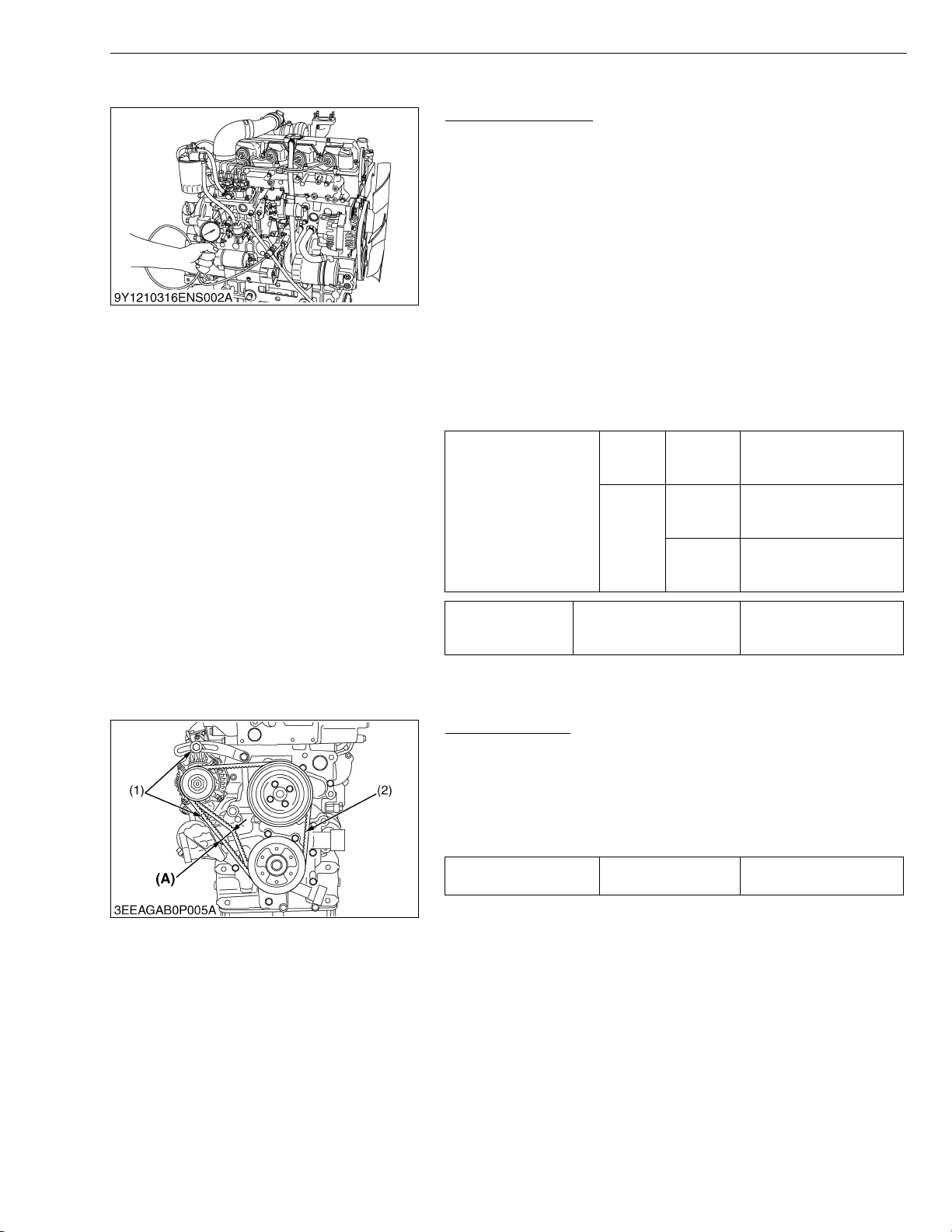
V3307-DI-T-E2B, WSM
KiSC issued 01, 2009 A
(2) Lubricating System
ENGINE
Engine Oil Pressure
1. Remove the oil switch and set a pressure tester (Code No.
07916-32032).
2. Start the engine. After warming up, measure the oil pressure of
both idling and rated speeds.
3. If the oil pressure is less than the allowable limit, check the
following.
• Engine oil insufficient
• Oil pump defective
• Oil strainer clogged
• Oil filter cartridge clogged
• Oil gallery clogged
• Excessive oil clearance
• Foreign matter in the relief valve
(When reassembling)
• After checking the engine oil pressure, tighten the engine oil
pressure switch to the specified torque.
49 kPa
0.50 kgf/cm
7.1 psi
197 to 392 kPa
2.00 to 4.00 kgf/cm
28.5 to 56.8 psi
147 kPa
1.50 kgf/cm
21.3 psi
2
2
2
Engine oil pressure
At idle
speed
At rated
speed
Allowable
limit
Factory
spec.
Allowable
limit
(3) Cooling System
Tightening torque Oil switch taper screw
15 to 19 N·m
1.5 to 2.0 kgf·m
11 to 14 lbf·ft
W10349520
Fan Belt Tension
1. Measure the deflection (A), depressing the fan belt (2) halfway
between the fan drive pulley and alternator pulley at specified
force 98 N (10 kgf, 22 lbf).
2. If the measurement is not within the factory specifications, loosen
the alternator mounting screws (1) and relocate the alternator to
adjust.
Deflection (A) Factory spec.
(1) Alternator Mounting Screw
(2) Fan Belt
(A) Deflection
10.0 to 12.0 mm
0.394 to 0.472 in.
W1082347
S-17
Page 87
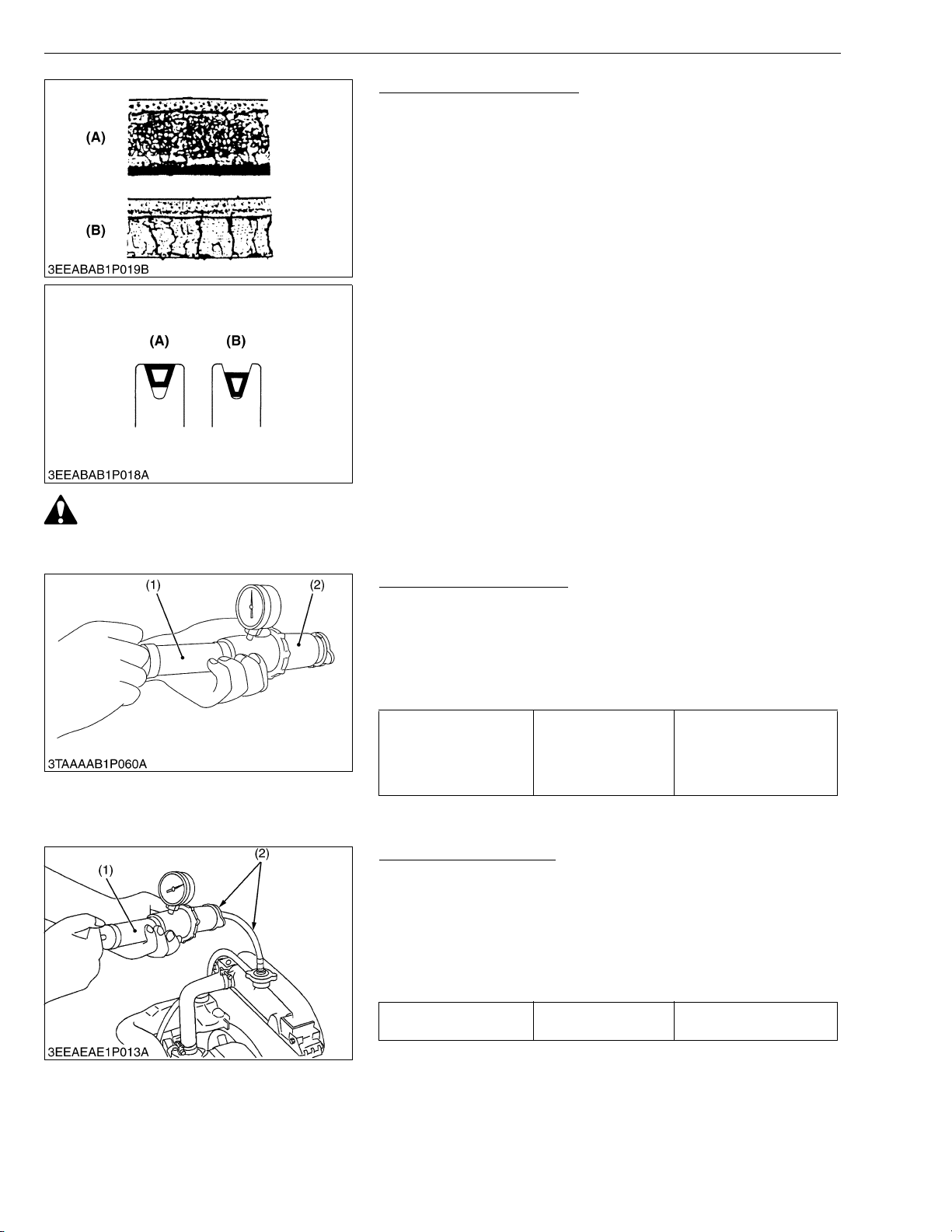
V3307-DI-T-E2B, WSM
KiSC issued 01, 2009 A
ENGINE
Fan Belt Damage and Wear
1. Check the fan belt for damage.
2. If the fan belt is damaged, replace it.
3. Check if the fan belt is worn and sunk in the pulley groove.
4. If the fan belt is nearly worn out and deeply sunk in the pulley
groove, replace it.
(A) Good (B) Bad
W1021108
CAUTION
• When removing the radiator cap, wait at least ten minutes after the engine has stopped and cooled down.
Otherwise, hot water may gush out, scalding nearby people.
Radiator Cap Air Leakage
1. Set a radiator tester (1) and an adaptor (2) on the radiator cap.
2
2. Apply the specified pressure of 88 kPa (0.90 kgf/cm
, 13 psi), and
measure the time for the pressure to fall to 59 kPa (0.60 kgf/cm
8.5 psi).
3. If the measurement is less than the factory specification, replace
the radiator cap.
More than 10 seconds
Pressure falling time Factory spec.
(1) Radiator Tester (2) Adaptor
for pressure fall
88 → 59 kPa
(0.90 → 0.60 kgf/cm
13 → 8.5 psi)
2
,
W1054156
Radiator Water Leakage
1. Pour a specified amount of water into the radiator.
2. Set a radiator tester (1) and an adaptor (2) and raise the water
pressure to the specified pressure.
3. Check the radiator for water leaks.
4. For water leak from the pinhole, replace the radiator or repair with
the radiator cement. When water leak is excessive, replace the
radiator.
Radiator water leakage
test pressure
Factory spec.
No leak at specified
pressure
2
,
NOTEQ
• The pressure of the leak test is different from each radiator
specification.
Thus, do the leak test, refer to the test pressure of each
radiator specification.
(1) Radiator Tester (2) Adaptor
W1016903
S-18
Page 88
V3307-DI-T-E2B, WSM
KiSC issued 01, 2009 A
ENGINE
Thermostat Valve Opening Temperature
1. Push down the thermostat valve and insert a string between the
valve and the valve seat.
2. Place the thermostat and a thermostat in a container with water
and gradually heat the water.
3. Hold the string to suspend the thermostat in the water. When the
water temperature rises, the thermostat valve will open, allowing
it to fall down from the string.
Read the temperature at this moment on the thermometer.
4. Continue heating the water and read the temperature when the
valve has risen by about 8 mm (0.3 in.).
5. If the measurement is not acceptable, replace the thermostat.
Thermostat’s valve
opening temperature
Temperature at which
thermostat completely
opens
Factory spec.
Factory spec.
74.5 to 78.5 °C
166.1 to 173.3 °F
90 °C
194 °F
W1071639
S-19
Page 89
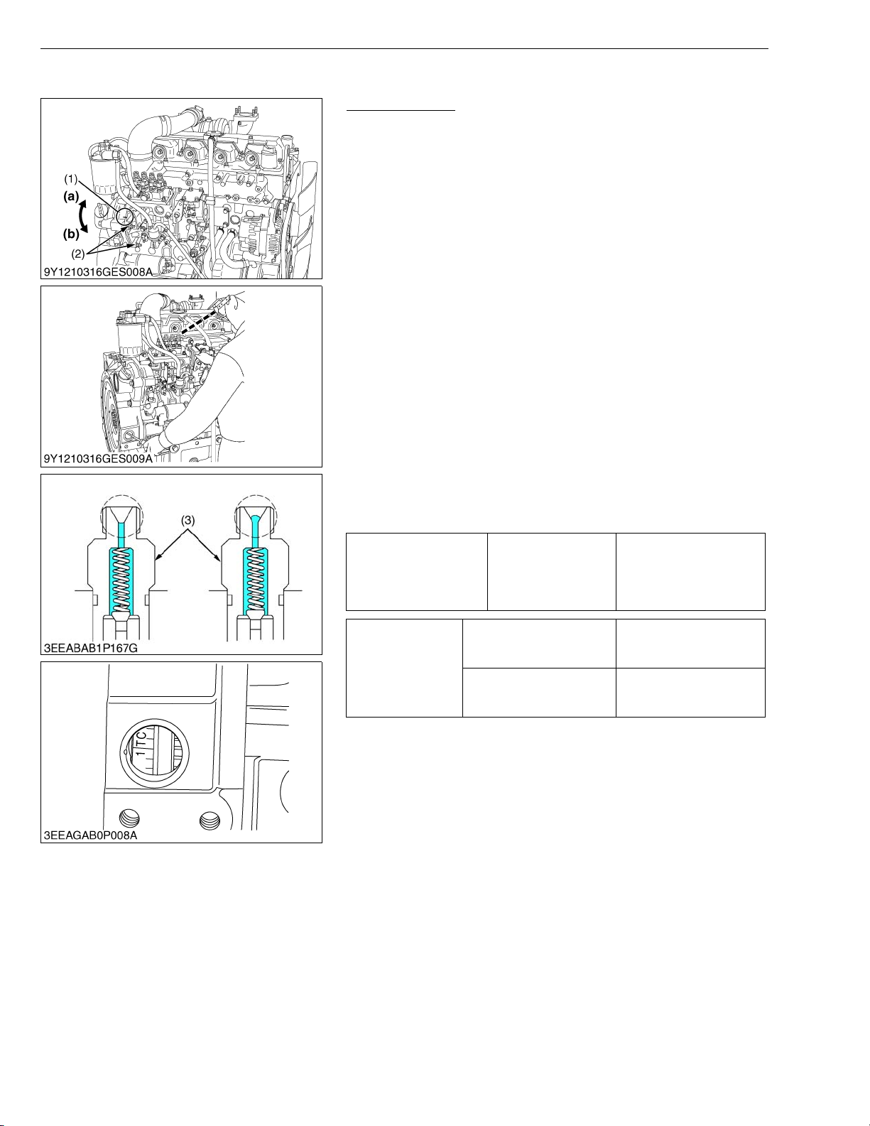
V3307-DI-T-E2B, WSM
KiSC issued 01, 2009 A
(4) Fuel System
ENGINE
Injection Timing
1. Make sure of matching the injection timing align mark (1) of the
injection pump unit and the flywheel housing, as shown in the
illustration.
2. Remove the injection pipes.
3. Remove the stop solenoid.
4. Turn the flywheel counterclockwise (viewed from flywheel side)
until the fuel fills up to the hole of the delivery valve holder (3) for
No.1 cylinder.
5. After the fuel fills up to the hole of the delivery valve holder (3) for
No.1 cylinder, turn back (clockwise) the flywheel around 1.6 rad
(90 °).
6. Turn the flywheel counterclockwise to set at around 0.17 rad
(10 °) before T.D.C..
7. Slowly turn the flywheel counterclockwise and stop turning when
the fuel begins to come up, to get the present injection timing.
8. Check to see the degree on flywheel.
The flywheel has mark “1TC” for the crank angle before the top
dead center of No.1 piston.
9. If the injection timing is not within the specification, rotate the
injection pump unit to adjust the injection timing.
IMPORTANTQ
• When installing the injection pump unit to the engine body,
follow the correct procedure.
See the “Injection Pump Unit”.
0.00436 rad before T.D.C.
to 0.0218 rad
Injection timing Factory spec.
after T.D.C.
(0.250 ° before T.D.C. to
1.25 ° after T.D.C.)
Injection pipe retaining nut
Tightening torque
Injection pump unit
mounting nut
(1) Injection Timing Align Mark
(2) Injection Pump Unit Mounting Nut
(3) Delivery Valve Holder
23 to 36 N·m
2.3 to 3.7 kgf·m
17 to 26 lbf·ft
18 to 20 N·m
1.8 to 2.1 kgf·m
13 to 15 lbf·ft
(a) Injection Timing Advanced
(b) Injection Timing Retarded
W1089274
S-20
Page 90
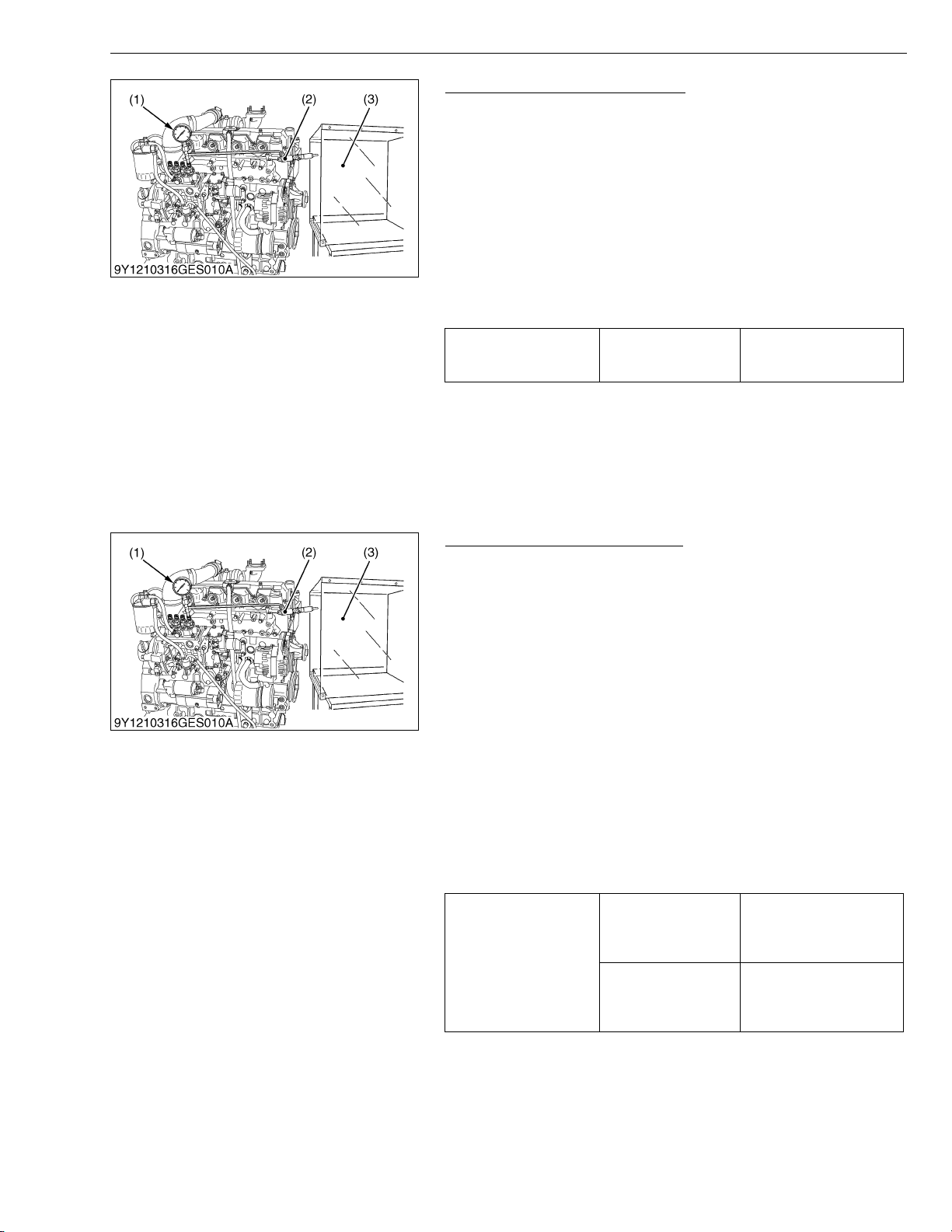
V3307-DI-T-E2B, WSM
KiSC issued 01, 2009 A
ENGINE
Fuel Tightness of Pump Element
1. Remove the engine stop solenoid.
2. Remove the injection pipes.
3. Install the injection pump pressure tester (1) to the injection
pump.
4. Install the injection nozzle (2) jetted with the proper injection
pressure to the injection pump pressure tester (1). (Refer to the
figure.)
5. Set the speed control lever to the maximum speed position.
6. Run the starter to increase the pressure.
7. If the pressure can not reach the allowable limit, replace the
pump with new one or repair with a Kubota-authorized pump
service shop.
Fuel tightness of pump
element
Allowable limit
18.63 MPa
190.0 kgf/cm
2702 psi
2
NOTEQ
• Never try to disassemble the injection pump assembly. For
repairs, you are strongly requested to contact a Kubotaauthorized pump service shop.
(1) Injection Pump Pressure Tester
(2) Injection Nozzle
(3) Protection Cover for Jetted Fuel
W1017430
Fuel Tightness of Delivery Valve
1. Remove the engine stop solenoid.
2. Remove the injection pipes.
3. Install a pressure tester to the fuel injection pump.
4. Install the injection nozzle (2) jetted with the proper injection
pressure to the injection pump pressure tester (1).
5. Run the starter to increase the pressure.
6. Stop the starter when the fuel jets from the injection nozzle (2).
After that, turn the flywheel by the hand and raise the pressure to
approx. 18.63 MPa (190.0 kgf/cm
2
, 2702 psi).
7. Now turn the flywheel back about half a turn (to keep the plunger
free). Maintain the flywheel at this position and clock the time
taken for the pressure to drop from 18.63 to 17.65 MPa (from
190.0 to 180.0 kgf/cm
8. Measure the time needed to decrease the pressure from 18.63 to
17.65 MPa (from 190.0 to 180.0 kgf/cm
2
, from 2702 to 2560 psi).
2
, from 2702 to 2560 psi).
9. If the measurement is less than allowable limit, replace the pump
with new one or repair with a Kubota-authorized pump service
shop.
10 seconds
Factory spec.
Fuel tightness of
delivery valve
Allowable limit
18.63 → 17.65 MPa
190.0 → 180.0 kgf/cm
2702 → 2560 psi
5 seconds
18.63 → 17.65 MPa
190.0 → 180.0 kgf/cm
2702 → 2560 psi
2
2
NOTEQ
• Never try to disassemble the injection pump assembly. For
repairs, you are strongly requested to contact a Kubotaauthorized pump service shop.
(1) Injection Pump Pressure Tester
(2) Injection Nozzle
(3) Protection Cover for Jetted Fuel
W1017786
S-21
Page 91
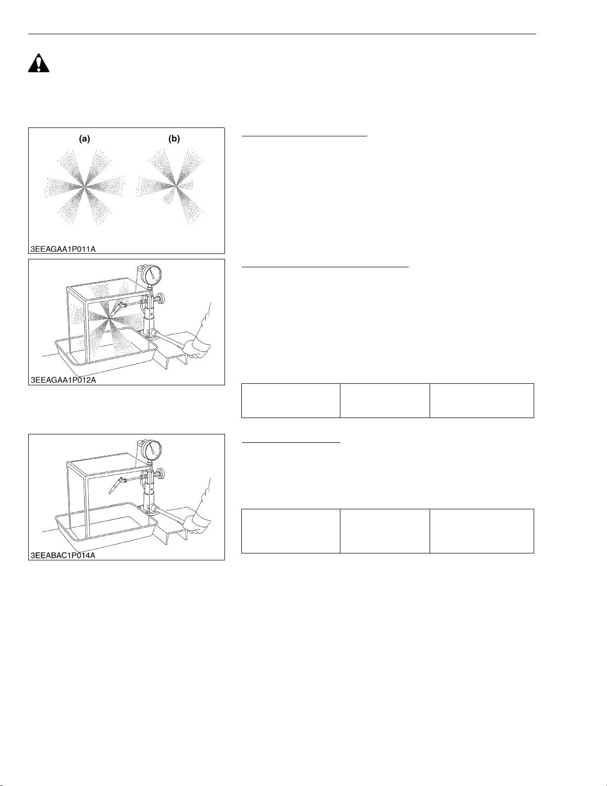
V3307-DI-T-E2B, WSM
KiSC issued 01, 2009 A
ENGINE
CAUTION
• Check the nozzle injection pressure and condition after confirming that there is nobody standing in the
direction the spray goes.
• If the spray from the nozzle directly contacts the human body, cells may be destroyed and blood poisoning
may be caused.
Nozzle Spraying Condition
1. Attach the injection nozzle to the nozzle tester, and check the
nozzle spraying condition.
2. If the spraying condition is defective, replace the injection nozzle
assembly or repair at Kubota-authorized nozzle service shop.
(a) Good (b) Bad
W10371670
Checking Nozzle Injection Pressure
1. Attach the injection nozzle to the nozzle tester.
2. Slowly move the tester handle to measure the pressure at which
fuel begins jetting out from the nozzle.
3. If the measurement is not within the factory specifications,
replace the injection nozzle assembly or repair at Kubotaauthorized nozzle service shop.
NOTEQ
• Injection nozzle gasket must be replaced when the injection
nozzle is removed for checking.
Injection pressure
(1st stage)
Factory spec.
18.64 to 19.61 MPa
190.0 to 200.0 kgf/cm
2703 to 2844 psi
W1037280
2
Valve Seat Tightness
1. Attach the injection nozzle to the nozzle tester.
2. Raise the fuel pressure, and keep at 16.67 MPa (170.0 kgf/cm
2418 psi) for 10 seconds.
3. If any fuel leak is found, replace the injection nozzle assembly or
repair at Kubota-authorized nozzle service shop.
No fuel leak at
Valve seat tightness Factory spec.
16.67 MPa
170.0 kgf/cm
2418 psi
2
2
,
W10374150
S-22
Page 92
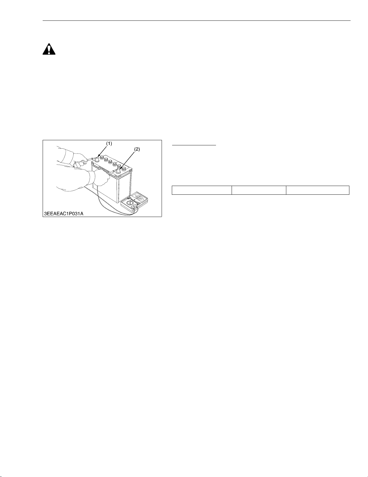
V3307-DI-T-E2B, WSM
KiSC issued 01, 2009 A
ENGINE
(5) Electrical System
CAUTION
• To avoid accidental short circuit, be sure to attach the positive cable to the positive terminal before the
negative cable is attached to the negative terminal.
• Never remove the battery cap while the engine is running.
• Keep electrolyte away from eyes, hands and clothes. If you are spattered with it, wash it away completely
with water immediately.
• Keep open sparks and flames away from the battery at all times. Hydrogen gas mixed with oxygen
becomes very explosive.
IMPORTANTQ
• If the machine is to be operated for a short time without battery (using a slave battery for starting), use
additional current (lights) while engine is running and insulate terminal of battery. If this advice is
disregarded, damage to alternator and regulator may result.
Battery Voltage
1. Stop the engine.
2. Measure the voltage with a circuit tester between the battery
terminals.
3. If the battery voltage is less than the factory specification, check
the battery specific gravity and recharge the battery.
Battery voltage Factory spec. More than 12 V
(1) Positive Terminal (2) Negative Terminal
W10125620
S-23
Page 93
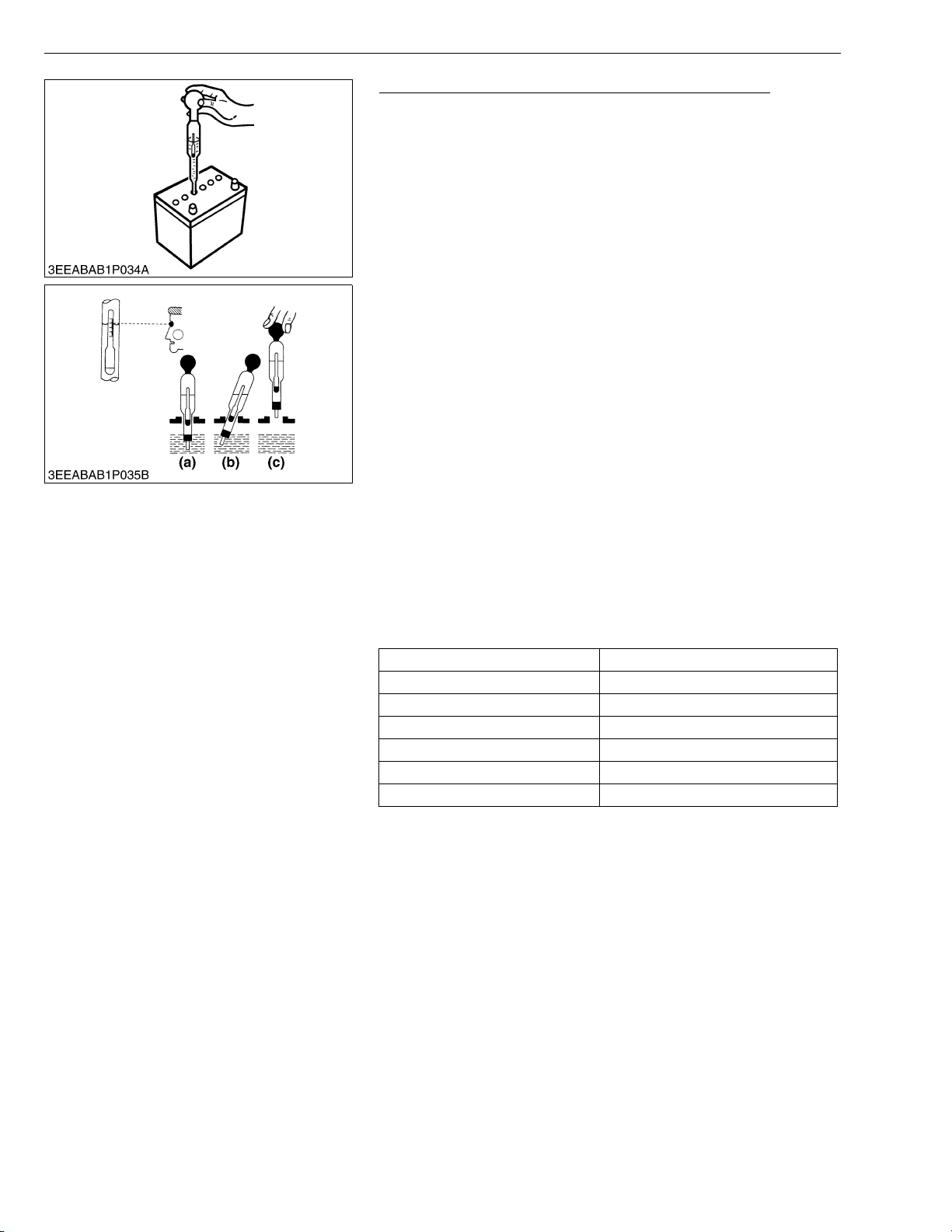
V3307-DI-T-E2B, WSM
KiSC issued 01, 2009 A
ENGINE
Battery Specific Gravity (for Refillable Battery’s only)
1. Check the specific gravity of the electrolyte in each cell with a
hydrometer.
2. When the electrolyte temperature differs from that at which the
hydrometer was calibrated, correct the specific gravity reading
following the formula mentioned in (Reference).
3. If the specific gravity is less than 1.215 (after it is corrected for
temperature), charge or replace the battery.
4. If the specific gravity differs between any two cells by more than
0.05, replace the battery.
NOTEQ
• Hold the hydrometer tube vertical without removing it from
the electrolyte.
• Do not suck too much electrolyte into the tube.
• Allow the float to move freely and hold the hydrometer at eye
level.
• The hydrometer reading must be taken at the highest
electrolyte level.
(Reference)
• Specific gravity slightly varies with temperature. To be exact, the
specific gravity decreases by 0.0007 with an increase of 1 °C
(0.0004 with an increase of 1 °F) in temperature, and increases
by 0.0007 with a decreases of 1 °C (0.0004 with a decrease of 1
°F).
Therefore, using 20 °C (68 °F) as a reference, the specific gravity
reading must be corrected by the following formula :
- Specific gravity at 20 °C = Measured value + 0.0007 ×
(electrolyte temperature : 20 °C)
- Specific gravity at 68 °F = Measured value + 0.0004 ×
(electrolyte temperature : 68 °F)
Specific Gravity State of Charge
1.260 Sp. Gr. 100 % Charged
1.230 Sp. Gr. 75 % Charged
1.200 Sp. Gr. 50 % Charged
1.170 Sp. Gr. 25 % Charged
1.140 Sp. Gr. Very Little Useful Capacity
1.110 Sp. Gr. Discharged
At an electrolyte temperature of 20 °C (68 °F)
(a) Good
(b) Bad
(c) Bad
W1019017
S-24
Page 94
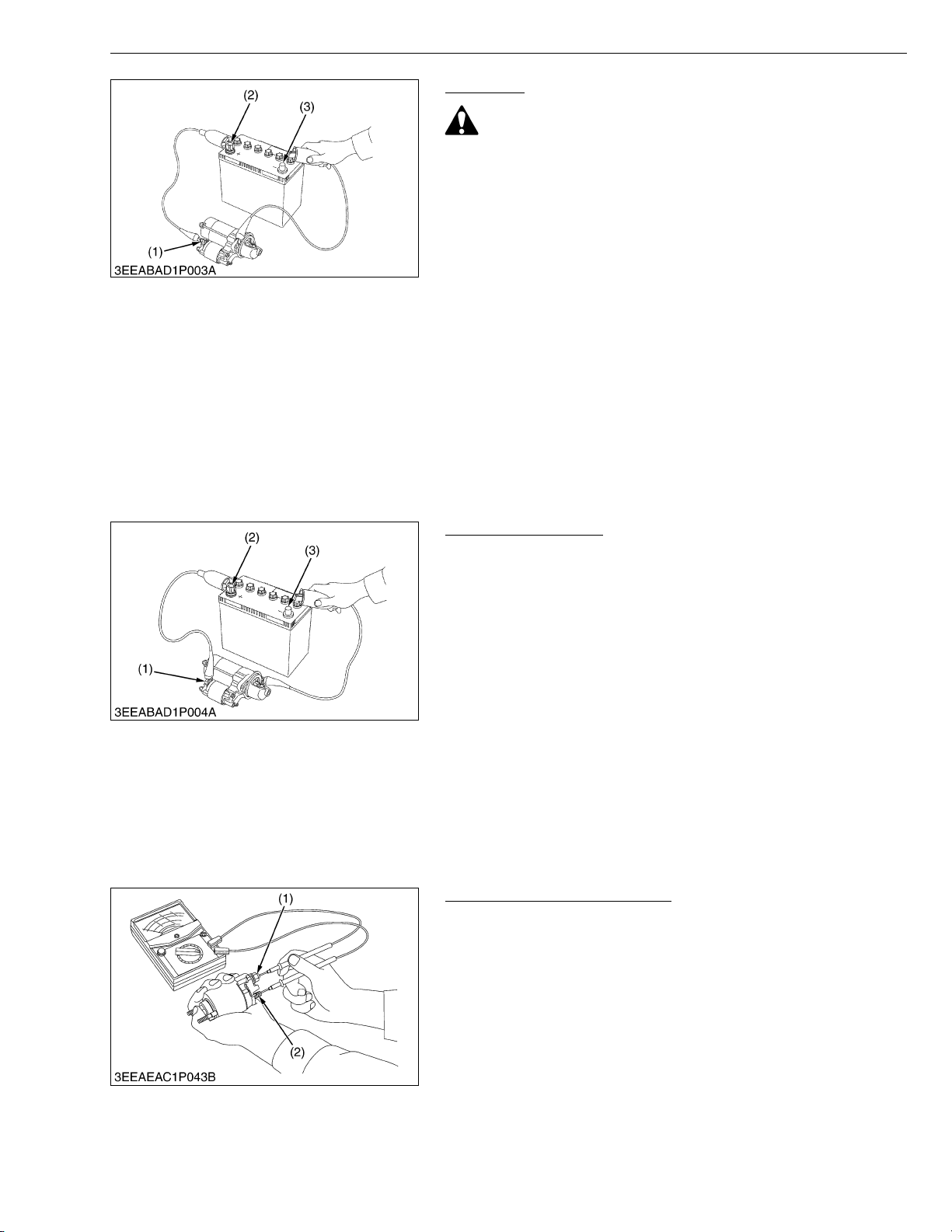
V3307-DI-T-E2B, WSM
KiSC issued 01, 2009 A
ENGINE
Motor Test
CAUTION
• Secure the starter to prevent it from jumping up and down
while testing the motor.
1. Disconnect the battery negative cable from the battery.
2. Disconnect the battery positive cable from the battery.
3. Disconnect the leads from the starter B terminal.
4. Remove the starter from the engine.
5. Connect a jumper lead from the starter C terminal (1) to the
battery positive terminal (2).
6. Connect a jumper lead momentarily between the starter’s body
and the battery negative terminal (3).
7. If the motor does not run, starter is failure.
Repair or replace the starter.
NOTEQ
• B terminal : It is the terminal which connects the cable from
the battery to the starter.
• C terminal : It is the terminal which connects the cable from
the motor to the magnet switch.
(1) C Ter m in a l
(2) Positive Terminal
(3) Negative Terminal
W1019297
Magnetic Switch Test
1. Disconnect the battery negative cable from the battery.
2. Disconnect the battery positive cable from the battery.
3. Disconnect the leads from the starter B terminal.
4. Remove the starter from the engine.
5. Connect a jumper lead from the starter S terminal (1) to the
battery positive terminal (2).
6. Connect a jumper lead momentarily between the starter’s body
and the battery negative terminal (3).
7. If the pinion gear does not pop out, the magnetic switch is failure.
Repair or replace the starter.
NOTEQ
• B terminal : It is the terminal which connects the cable from
the battery to the starter.
• S terminal : It is the terminal which connects the cable from
the starter switch to the magnet switch.
(1) S Terminal
(2) Positive Terminal
(3) Negative Terminal
0000010743E
Magnet Switch Continuity Test
1. Check the continuity across the C terminal (1) and the B terminal
(2) with a circuit tester, pushing in the plunger.
2. If not continuous or if a certain value is indicated, replace the
magnet switch.
(1) C Ter m in a l ( 2 ) B Terminal
0000010771E
S-25
Page 95
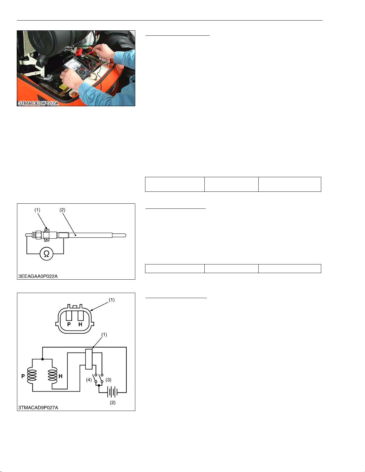
V3307-DI-T-E2B, WSM
KiSC issued 01, 2009 A
ENGINE
Alternator on Unit Test
(Before testing)
• Before alternator on unit test, check the battery terminal
connections, circuit connection, fan belt tension, charging
indicator lamp, fuses on the circuit, and abnormal noise from the
alternator.
• Prepare full charged battery for the test.
NOTEQ
• Be careful not to touch the rotating engine parts while
engine is running.
Keep safety distance from the engine rotating parts.
1. Start the engine.
2. When the engine is operating measure the voltage between two
battery terminals. If the voltage is between 13.8 V and 14.8 V,
the alternator is operating normally.
3. If the results of alternator on unit test are not within the
specifications, disassemble the alternator and check the each
component part for finding out the failure. See the
“DISASSEMBLING AND ASSEMBLING” and “SERVICING” for
alternator.
Regulating voltage at no
load
Factory spec.
13.8 to 14.8 V at
25 °C (77 °F)
0000010745E
Glow Plug Continuity
1. Remove the glow plug (2).
2. Measure the resistance with a circuit tester between the glow
plug terminal and the glow plug housing.
3. If the factory specification is not indicated, glow plug (2) is faulty.
NOTEQ
• Adjust the direction of the ditch to the terminal side when
the seal (1) is installed in the glow plug (2).
Resistance Factory spec. Approx. 0.95 Ω
(1) Seal (2) Glow Plug
W1036945
Engine Stop Solenoid
1. Remove the engine stop solenoid from the engine.
2. Connect the jumper leads from the pulling coil P terminal to the
switch (3), and from switch (3) to the battery positive terminal.
3. Connect the jumper leads from the holding coil H terminal to the
switch (4), and from switch (4) to the battery positive terminal.
4. Connect the jumper leads from the engine stop solenoid body to
the battery negative terminal.
5. When switch (4) is turn on, the plunger pull into the solenoid body
and then turn off the switch (4), the plunger comes out.
6. Turn on the switch (3) then turn on the switch (4), the plunger pull
into the solenoid body and it keep in holding position after turn off
the switch (4).
7. If the plunger is not attracted, the engine stop solenoid is faulty.
IMPORTANTQ
• Never apply the current for pulling coil more than two
seconds when inspecting.
(1) Connector
(2) Battery
(3) Switch for Holding Coil
(4) Switch for Pulling Coil
P : Terminal for Pulling Coil
H : Terminal for Holding Coil
W1020600
S-26
Page 96
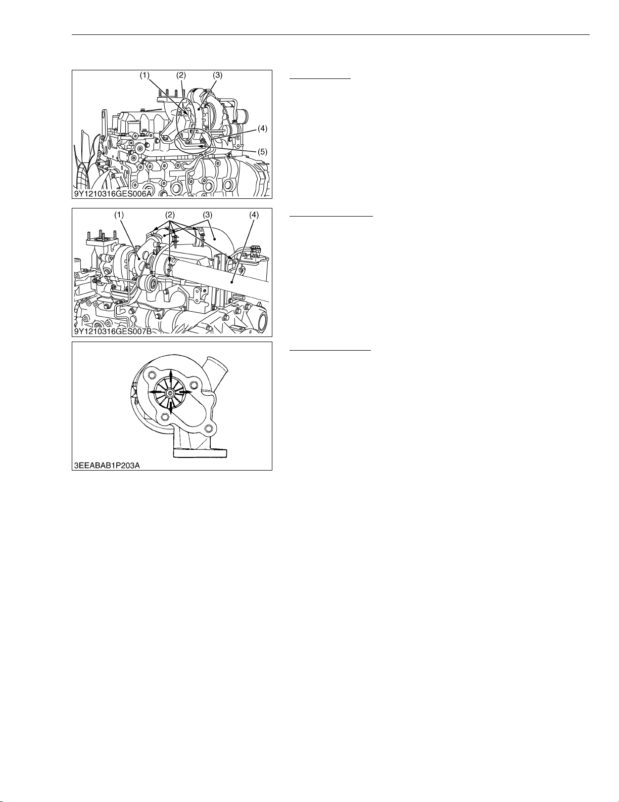
V3307-DI-T-E2B, WSM
KiSC issued 01, 2009 A
(6) Turbocharger
ENGINE
Turbine Side
1. Check the exhaust port (2) and inlet port (4) side of turbine
housing (3) to see if there is no exhaust gas leak.
2. If any gas leak is found, retighten the bolts and nuts or replace
the gasket (1) / (5) with new one.
(1) Gasket
(2) Exhaust Port
(3) Turbine Housing
(4) Inlet Port
(5) Gasket
W1076917
Compressor Side
1. Check the inlet hose (4) of the compressor cover (1) to see if
there is no air leak.
2. Check for loose connections or cracks in the suction side of the
intake hose (3).
3. If any air leak is found, change the clamp band (2) and / or intake
hoses (3).
(1) Compressor Cover
(2) Clamp Band
(3) Intake Hose
(4) Inlet Hose
W1077032
Radial Clearance
1. If the wheel contact to the housing, replace the turbocharger
assembly with new one.
W1077353
S-27
Page 97
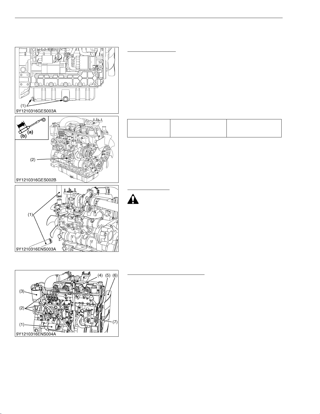
V3307-DI-T-E2B, WSM
KiSC issued 01, 2009 A
[2] DISASSEMBLING AND ASSEMBLING
(1) Draining Oil and Coolant
Draining Engine Oil
1. Start and warm up the engine for approx. 5 minutes.
2. Place an oil pan underneath the engine.
3. Remove the drain plug (1) to drain oil.
4. After draining, screw in the drain plug (1).
(When refilling)
• Fill the engine oil up to the upper line on the dipstick (2).
IMPORTANTQ
• Never mix two different types of oil.
• Use the proper SAE Engine Oil according to ambient
temperature.
Tightening torque Drain plug
ENGINE
45 to 53 N·m
4.5 to 5.5 kgf·m
33 to 39 lbf·ft
(2) External Components
(1) Drain Plug
(2) Dipstick
(a) Upper Line
(b) Lower Line
W1023464
Draining Coolant
CAUTION
• Never remove radiator cap while operating or immediately
after stopping. Otherwise, hot water will spout out from the
radiator. Wait for more than ten minutes to cool the radiator,
before opening the cap.
1. Open the radiator drain plug and remove the radiator cap.
2. Remove the radiator hose (1) from engine body.
(1) Radiator Hose
W1023496
Air Cleaner, Muffler and Others
1. Remove the air cleaner and muffler.
2. Remove the fan (6), fan belt (5), breather hose (4), fuel filter
cartridge (3), fuel tubes (2), alternator (7) and starter (1).
(When reassembling)
• Check to see that there are no cracks on the belt surface.
• Mount the check valve with the ↓ mark toward the tank.
IMPORTANTQ
• After reassembling the fan belt (5), be sure to adjust the fan
belt tension.
• Do not confuse the direction of the fan (6). Attach the fan (6)
with its marking facing frontward (toward the radiator).
(1) Starter
(2) Fuel Tube
(3) Fuel Filter Cartridge
(4) Breather Hose
(5) Fan Belt
(6) Fan
(7) Alternator
W1049622
S-28
Page 98
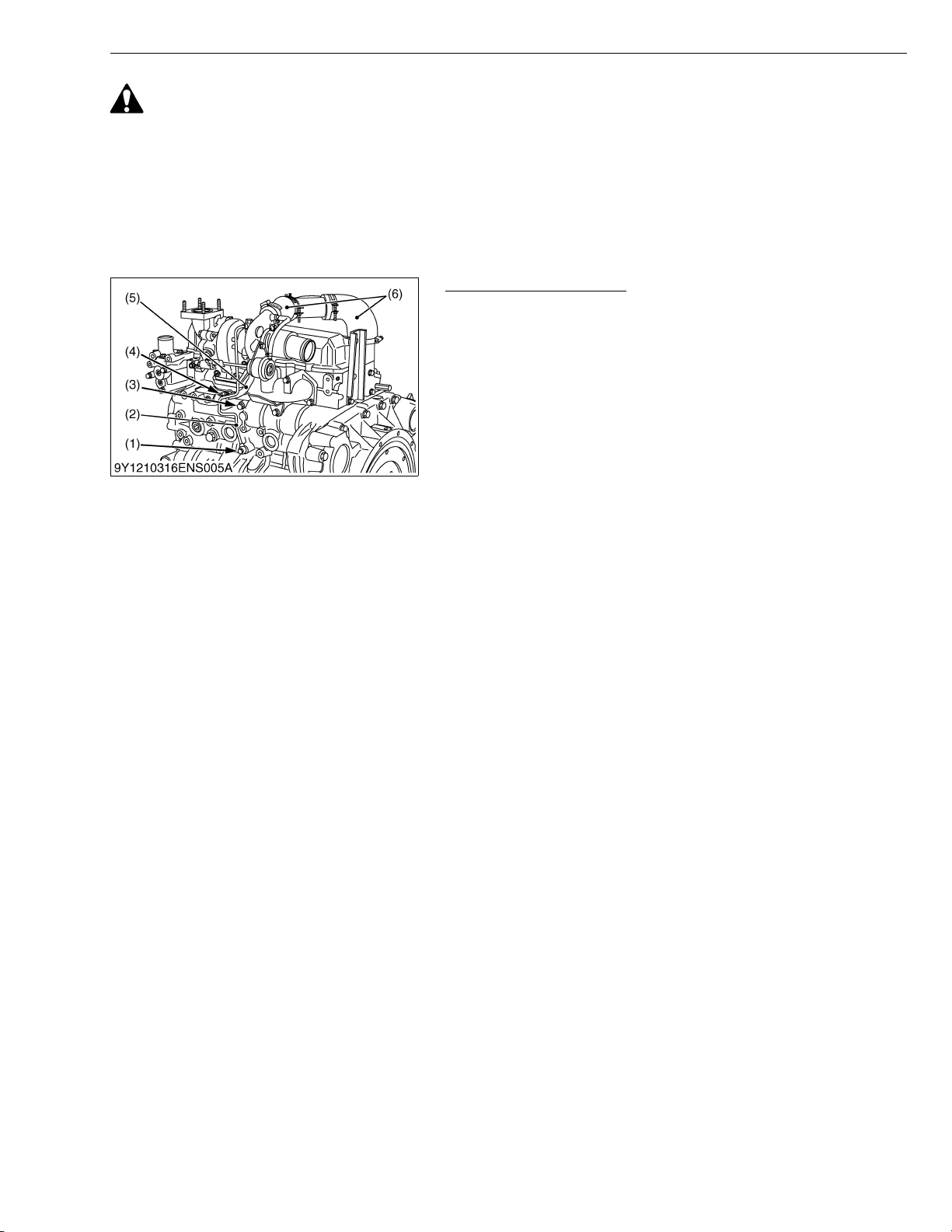
V3307-DI-T-E2B, WSM
KiSC issued 01, 2009 A
ENGINE
CAUTION
• While the engine is running and or just after it stops, the turbocharger is hot, be careful not to touch the
turbocharger.
NOTEQ
• When detaching and attaching the turbocharger assembly, be very careful not to allow dust, dirt and other
foreign matter in the oil pipes.
• When the turbocharger assembly has been replace, pour fresh engine oil through the oil filler port of the
turbocharger.
• Before starting the engine, make sure that air cleaner is in position.
Oil Pipe and Intake Hose
1. Remove the joint bolt (1), bolt (3) and clamp band (4).
2. Disconnect the oil pipe 1 (2) and oil pipe 2 (5).
3. Remove the intake hose (6).
(When reassembling)
• Pour fresh engine oil through the oil filler port of the turbocharger.
• Replace the gasket with new one.
• Be careful not to allow dust, dirt and other foreign matters in the
oil pipes (2) / (5).
NOTEQ
• Tape or plug all openings to prevent foreign matters from
damaging the oil cavities in the turbocharger.
(1) Joint Bolt
(2) Oil Pipe 1
(3) Bolt
(4) Clamp Band
(5) Oil Pipe 2
(6) Intake Hose
W1025983
S-29
Page 99
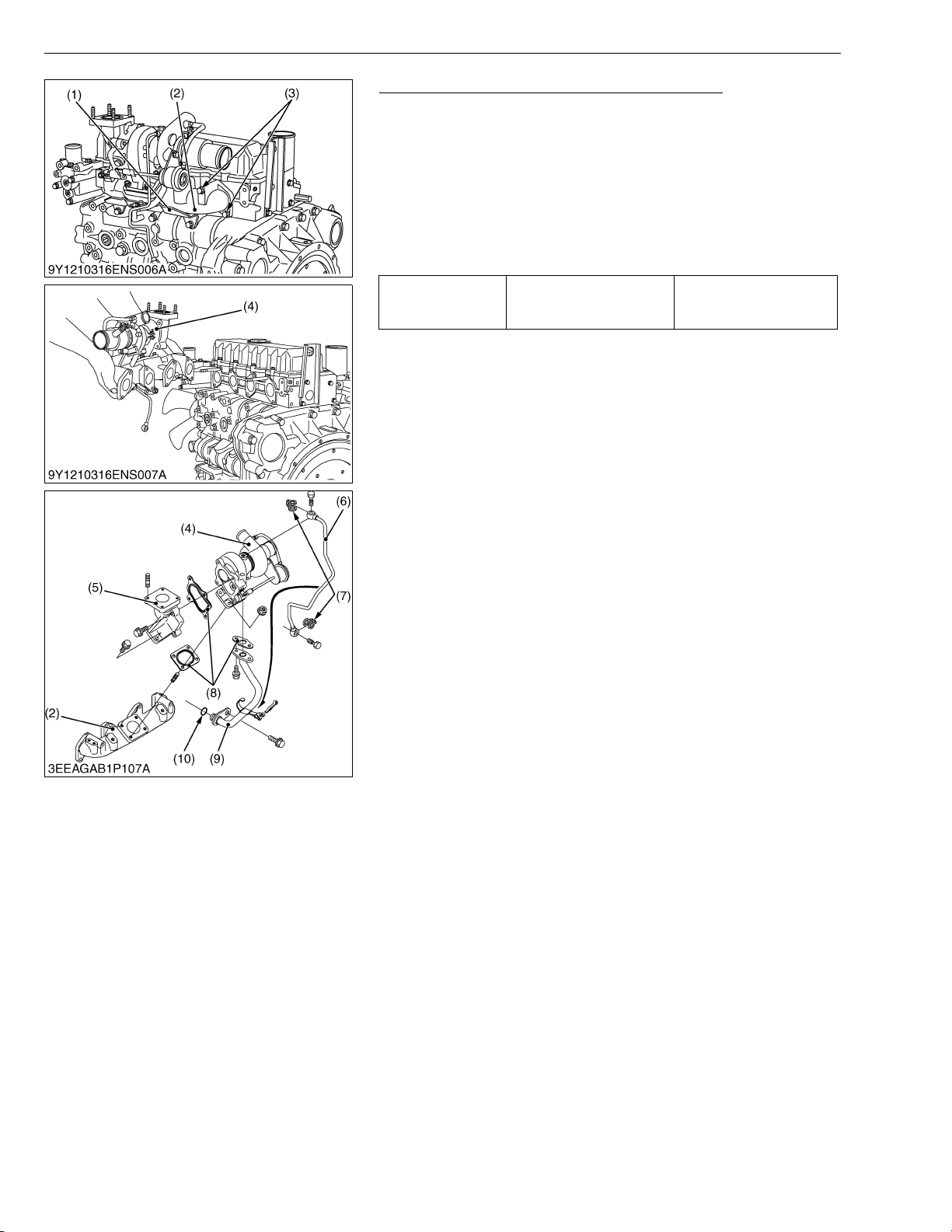
V3307-DI-T-E2B, WSM
KiSC issued 01, 2009 A
ENGINE
Turbocharger Assembly and Exhaust Manifold
1. Remove the cover (1) and exhaust manifold mounting screws (3).
2. Take off the turbocharger assembly (4) with exhaust manifold (2).
3. Remove the oil pipe 1 (6) and oil pipe 2 (9). (If necessary)
4. Remove the exhaust port (5) and exhaust manifold (2). (If
necessary)
(When reassembling)
• Replace the gasket (8) with new one.
NOTEQ
• Be careful not to damage the O-ring (10).
Tightening torque Oil pipe 1 mounting screw
16 to 19 N·m
1.6 to 2.0 kgf·m
12 to 14 lbf·ft
(1) Cover
(2) Exhaust Manifold
(3) Exhaust Manifold Mounting Screw
(4) Turbocharger Assembly
(5) Exhaust Port
(6) Oil Pipe 1
(7) Oil Pipe Gasket
(8) Gasket
(9) Oil Pipe 2
(10) O-ring
W1078106
S-30
Page 100
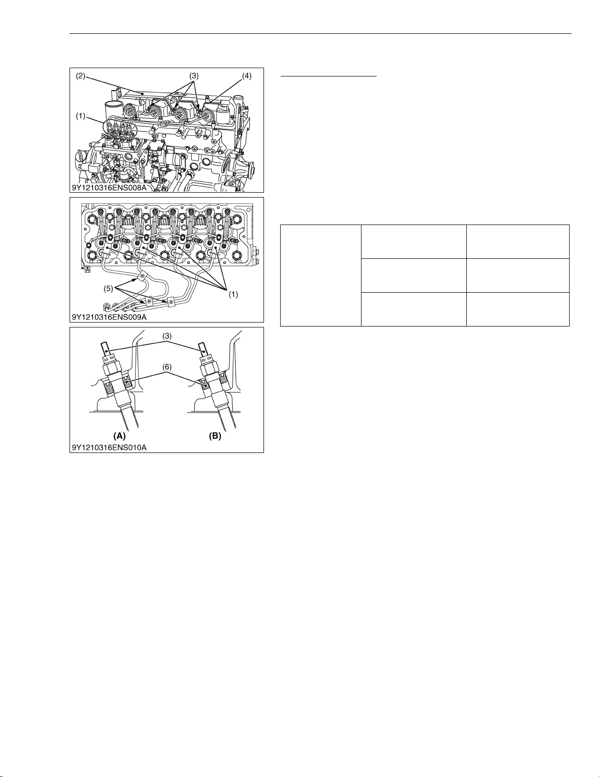
V3307-DI-T-E2B, WSM
KiSC issued 01, 2009 A
(3) Cylinder Head and Valves
ENGINE
Cylinder Head Cover
1. Remove the glow lead (4) and the glow plugs (3).
2. Remove the injection pipes (1).
3. Remove the cylinder head cover (2).
(When reassembling)
• Check to see that the cylinder head cover gasket is not detective.
• Tighten the head cover mounting screws to specified torque.
• Check the position of the injection pipe clamps (5) to reduce the
vibration of the injection pipes (1). (See the figure.)
• Adjust the direction of the ditch to the terminal side when the seal
(6) is installed in the glow plug (3).
• After installing the glow plug (3), confirm that the seal (6) was set
to the specified position.
9.81 to 11.2 N·m
1.00 to 1.15 kgf·m
7.24 to 8.31 lbf·ft
23 to 36 N·m
2.3 to 3.7 kgf·m
17 to 26 lbf·ft
7.7 to 9.3 N·m
0.78 to 0.95 kgf·m
5.7 to 6.8 lbf·ft
Tightening torque
Cylinder head cover screw
Injection pipe retaining nut
Glow plug
(1) Injection Pipe
(2) Cylinder Head Cover
(3) Glow Plug
(4) Glow Lead
(5) Injection Pipe Clamp
(6) Seal
(A) Good
(B) Bad
W1021753
S-31
 Loading...