

WSM V1505-CR-TE5 Workshop Manual

WORKSHOP MANUAL
KiSC issued 03, 2022 A
DIESEL ENGINE
V1505-CR-TE5

TO THE READER
KiSC issued 03, 2022 A
This workshop manual provides safety information for service activity, general information such as specifications and
dimensions of the machine, mechanisms and structure descriptions of the machine, and service procedures.
Safety
This section contains safety service descriptions and safety label information.
General
This section contains general instructions, tightening torques, general machine information and special tools.
Maintenance
This section contains information for the recommended oil and general maintenance procedures.
Each section basically consists of mechanism and servicing.
Mechanism
part
Mechanism
or component parts. This part should be comprehended before proceeding with troubleshooting, disassembling,
assembling, and servicing works.
Servicing
Servicing part contains information and procedures for maintenance, troubleshooting and repair works. The reader
should follow these instructions in order to satisfy any servicing work safely, correctly and quickly.
In this WSM, service specifications and service limits are defined as followings.
Service specifications:
Specification which corresponds to new machine's ex-factory. It is based on quality standard, drawings, or actual
measurements conducted by Kubota. This value is used to determine whether there is a problem with the machine in
the event of a troubleshooting. However, it is necessary to consider degradation due to wear, based on the operating
time of the machine, application or maintenance condition.
Service limits:
Service limit is a value corresponding to the recommended performance limit by taking long term-use wear into
account. When the service limit is reached, the machine is required to have proper repair, overhaul or replacement in
order to keep safe and adequate performance.
All of the illustrations, photographs, specifications, and other information in this manual were created based on the
latest model at the time of publication.
The parts names used in this manual are unified into names representing the functions of the parts. Therefore, it does
not necessarily correspond to the names used in other materials (parts list, operators manual etc.) and the name on
the label / identification plates on the product.
Kubota reserves the right to change all information at any time without notice.
contains information and explanations for the structure, functions, and specifications of the machine
© KUBOTA Corporation
January 2020

RECORD OF REVISIONS
V1505-CR-TE5
i
KiSC issued 03, 2022 A
Main revised contents and corrective measures are described in a table.
Find the main revised point and corrective measure through the reference page.
Last digit
of the code
No.
1 April 2020 Injector clamp Changed the tightening torque of injector clamp mounting screw.
2 February
3 March 2022 Alternator
Month of
revision
2021
Part name Main revised point and corrective measure
Correcting errors
Compression tester adapter To correct the specification value of the compression adapter. 2-23
Rail
Crankshaft bearing
Cylinder head bolt
Fan belt
Corrected the service specification of regulating voltage at no load
Corrected the description of function of rail assembly
Corrected the dimension value (inch) of crankshaft bearing 1.
Added the description of polished head bolt.
Changed the fan belt tension.
Reference
page
4-93
4-148
.
4-103
4-23
4-179
4-93
4-147
4-161

ii
V1505-CR-TE5
KiSC issued 03, 2022 A

CONTENTS
V1505-CR-TE5
iii
KiSC issued 03, 2022 A
1. SAFETY
SAFETY FIRST
1.
Working precautions.................................................................................................................................1-1
2. Preparing for emergencies .......................................................................................................................1-1
3. Working cautions ...................................................................................................................................... 1-2
4. Starting machine safely ............................................................................................................................1-2
5. Preventing fires......................................................................................................................................... 1-3
6. Preventing acid burns...............................................................................................................................1-3
7. Avoiding high pressure fluid......................................................................................................................1-3
8. Avoiding hot exhaust ................................................................................................................................1-4
9. Cleaning exhaust filter .............................................................................................................................. 1-4
2. GENERAL
GENERAL WORKING PRECAUTIONS ............................................................................................................2-1
1. Tightening bolts and nuts..........................................................................................................................2-1
2. Applying thread-locking fluid..................................................................................................................... 2-1
3. Installing circlips .......................................................................................................................................2-2
4. Handling liquid gasket ..............................................................................................................................2-2
5. Replacing O-rings.....................................................................................................................................2-2
6. Replacing oil seals.................................................................................................................................... 2-3
7. Handling the battery .................................................................................................................................2-3
8. Handling wire harness .............................................................................................................................. 2-4
9. Handling fuses..........................................................................................................................................2-5
10. Handling connectors...............................................................................................................................2-5
11. Wiring color ............................................................................................................................................. 2-6
12. Dispose fluids correctly........................................................................................................................... 2-6
ENGINE IDENTIFICATION ................................................................................................................................ 2-9
1. Engine model name and engine serial number ........................................................................................ 2-9
2. E5B engine ............................................................................................................................................. 2-10
3. Cylinder number .....................................................................................................................................2-11
MUFFLER FULL ASSEMBLY IDENTIFICATION.............................................................................................2-13
1. Part number and serial number (DPF) ...................................................................................................2-13
INFORMATION ................................................................................................................................................2-15
1. Specifications .........................................................................................................................................2-15
1.1 Specification for V1505-CR-TE5 ..................................................................................................... 2-15
2. Performance curves ...............................................................................................................................2-16
2.1 Performance curve for V1505-CR-TE5 ........................................................................................... 2-16
3. Dimensions.............................................................................................................................................2-17
3.1 Dimensions of V1505-CR-TE5........................................................................................................2-17
4. Wiring diagram .......................................................................................................................................2-18
4.1 Engine intermediate harness (Engine side harness) ......................................................................2-18
4.2 Injector intermediate harness (Engine side harness)......................................................................2-19
4.3 DPF intermediate harness (Engine side harness) ..........................................................................2-19
4.4 System wiring diagram....................................................................................................................2-21
SPECIAL TOOLS............................................................................................................................................. 2-23
1. Diesel engine compression tester ..........................................................................................................2-23
2. Oil pressure tester ..................................................................................................................................2-23
3. Compression tester adapter ...................................................................................................................2-23
4. Small end bushing replacing tool............................................................................................................ 2-25
5. Idle gear bushing replacing tool.............................................................................................................. 2-25
6. Valve guide replacing tool.......................................................................................................................2-26
7. Crankshaft sleeve press fit tool ..............................................................................................................2-27
8. Flywheel stopper ....................................................................................................................................2-27
9. Crankshaft bearing 1 replacing tool........................................................................................................2-28
..................................................................................................................................................1-1

10. Guide pin for suction control valve (SCV)............................................................................................. 2-28
iv
V1505-CR-TE5
KiSC issued 03, 2022 A
1
1. Air gap of the crankshaft position sensor measuring jig
.......................................................................2-29
12. Rotation sensor signal interface unit ....................................................................................................2-30
3. MAINTENANCE
MAINTENANCE CHECK LIST........................................................................................................................... 3-1
CHECK AND MAINTENANCE........................................................................................................................... 3-5
1. Daily check points..................................................................................................................................... 3-5
1.1 Checking engine oil level ..................................................................................................................3-5
1.2 Checking fuel level ............................................................................................................................ 3-5
1.3 Checking coolant level ......................................................................................................................3-6
1.4 Checking fan belt ..............................................................................................................................3-6
2. Check points of initial 50 hours................................................................................................................. 3-8
2.1 Changing engine oil ..........................................................................................................................3-8
2.2 Replacing oil filter cartridge...............................................................................................................3-8
3. Check point of every 50 hours..................................................................................................................3-9
3.1 Checking fuel hoses and clamp bands .............................................................................................3-9
3.2 Checking and draining water separator (Type 1) .............................................................................. 3-9
4. Check points of every 100 hours .............................................................................................................. 3-9
4.1 Checking radiator hose and clamp bands.........................................................................................3-9
4.2 Cleaning air cleaner primary element .............................................................................................3-10
4.3 Adjusting fan belt tension ................................................................................................................ 3-10
4.4 Checking intake air line ................................................................................................................... 3-11
5. Check point of every 250 hours..............................................................................................................3-12
5.1 Changing engine oil ........................................................................................................................3-12
6. Check points of every 400 hours ............................................................................................................ 3-12
6.1 Replacing fuel filter cartridge........................................................................................................... 3-12
6.2 Replacing oil filter cartridge.............................................................................................................3-13
6.3 Cleaning water separator (Type 1).................................................................................................. 3-13
7. Check points of every 500 hours ............................................................................................................ 3-13
7.1 Replacing water separator filter (Type 2) ........................................................................................ 3-13
7.2 Cleaning water jacket and radiator interior...................................................................................... 3-14
7.3 Replacing fan belt ...........................................................................................................................3-15
8. Check point of every 800 hours..............................................................................................................3-16
8.1 Checking valve clearance ...............................................................................................................3-16
9. Check points of every 1500 hours .......................................................................................................... 3-17
9.1 Checking injector (with Diagmaster) ...............................................................................................3-17
9.2 Checking EGR cooler...................................................................................................................... 3-18
9.3 Checking head cover valve ............................................................................................................. 3-19
10. Check points of every 3000 hours ........................................................................................................ 3-19
10.1 Checking turbocharger..................................................................................................................3-19
10.2 Checking EGR system (with Diagmaster).....................................................................................3-20
11. Check points of every 3000 to 6000 hours ...........................................................................................3-21
11.1 Cleaning DPF ................................................................................................................................3-21
11.2 Judging reuse of DPF filter comp before cleaning (Service dealer) ..............................................3-23
11.3 Judging reuse of DPF filter comp after cleaning (Cleaning contractor) ......................................... 3-23
12. Check points of every 1 year ................................................................................................................ 3-24
12.1 Replacing air cleaner element....................................................................................................... 3-24
12.2 Checking DPF differential pressure pipes and hoses ...................................................................3-25
12.3 Checking EGR piping....................................................................................................................3-25
12.4 Checking intake air line ................................................................................................................. 3-25
12.5 Checking exhaust manifold ........................................................................................................... 3-26
12.6 Replacing water hose.................................................................................................................... 3-26
13. Check points of every 2 years ..............................................................................................................3-26
13.1 Replacing fan belt .........................................................................................................................3-26
13.2 Replacing rubber hose of DPF differential pressure sensor..........................................................3-27
13.3 Replacing intake hose (after air flow sensor) and intercooler hose ..............................................3-27
13.4 Replacing EGR cooler hose..........................................................................................................3-27

13.5 Replacing lubricant hose...............................................................................................................3-28
V1505-CR-TE5
v
KiSC issued 03, 2022 A
13.6 Changing radiator coolant
13.7 Replacing radiator hose and clamp bands
.............................................................................................................3-28
....................................................................................3-29
13.8 Replacing fuel hose and clamps ...................................................................................................3-30
13.9 Replacing intake air line ................................................................................................................ 3-30
4. ENGINE
MECHANISM ..................................................................................................................................................... 4-1
1. General (Introduction)............................................................................................................................... 4-1
1.1 Feature of combustion (E-CDIS).......................................................................................................4-1
1.2 Structure of combustion (Center direct injection system (E-CDIS)) .................................................. 4-1
1.3 Flow of combustion (E-CDIS)............................................................................................................ 4-1
1.4 Control of combustion (E-CDIS)........................................................................................................ 4-2
2. Engine body.............................................................................................................................................. 4-3
2.1 Structure of engine body ................................................................................................................... 4-3
2.2 Feature of engine body .....................................................................................................................4-4
2.3 Crankcase ......................................................................................................................................... 4-4
2.3.1 Outline of crankcase ................................................................................................................. 4-4
2.3.2 Structure of crankcase..............................................................................................................4-4
2.3.3 Function of crankcase............................................................................................................... 4-4
2.3.4 Specification of crankcase ........................................................................................................ 4-4
2.4 Cylinder head .................................................................................................................................... 4-4
2.4.1 Outline of cylinder head ............................................................................................................ 4-4
2.4.2 Structure of cylinder head.........................................................................................................4-4
2.4.3 Function of cylinder head.......................................................................................................... 4-4
2.5 Cylinder head cover ..........................................................................................................................4-5
2.5.1 Outline of cylinder head cover ..................................................................................................4-5
2.5.2 Structure of cylinder head cover ............................................................................................... 4-5
2.5.3 Function of cylinder head cover................................................................................................4-5
2.6 Breather ............................................................................................................................................4-6
2.6.1 Outline of breather .................................................................................................................... 4-6
2.6.2 Structure of breather.................................................................................................................4-6
2.6.3 Function of breather.................................................................................................................. 4-6
2.7 Piston ................................................................................................................................................4-6
2.7.1 Outline of piston........................................................................................................................4-6
2.7.2 Structure of piston..................................................................................................................... 4-6
2.7.3 Function of piston .....................................................................................................................4-6
2.7.4 Specification of piston...............................................................................................................4-6
2.8 Piston ring .........................................................................................................................................4-7
2.8.1 Outline of piston ring.................................................................................................................4-7
2.8.2 Structure of piston ring.............................................................................................................. 4-7
2.8.3 Function of piston ring ..............................................................................................................4-7
2.8.4 Specification of piston ring........................................................................................................4-7
2.9 Connecting rod..................................................................................................................................4-7
2.9.1 Outline of connecting rod..........................................................................................................4-7
2.9.2 Structure of connecting rod....................................................................................................... 4-7
2.9.3 Function of connecting rod .......................................................................................................4-7
2.10 Crankshaft.......................................................................................................................................4-8
2.10.1 Outline of crankshaft...............................................................................................................4-8
2.10.2 Structure of crankshaft............................................................................................................ 4-8
2.10.3 Function of crankshaft ............................................................................................................4-8
2.10.4 Specification of crankshaft......................................................................................................4-8
2.11 Main bearing case ...........................................................................................................................4-8
2.11.1 Outline of main bearing case ..................................................................................................4-8
2.11.2 Structure of main bearing case ...............................................................................................4-8
2.11.3 Function of main bearing case ................................................................................................ 4-8
2.12 Flywheel .......................................................................................................................................... 4-9
2.12.1 Outline of flywheel ..................................................................................................................4-9

2.12.2 Structure of flywheel ...............................................................................................................4-9
vi
V1505-CR-TE5
KiSC issued 03, 2022 A
2.12.3 Function of flywheel
2.12.4 Specification of flywheel
................................................................................................................4-9
.........................................................................................................4-9
2.13 Rocker arm assembly .....................................................................................................................4-9
2.13.1 Outline of rocker arm assembly .............................................................................................. 4-9
2.13.2 Structure of rocker arm assembly...........................................................................................4-9
2.13.3 Function of rocker arm assembly............................................................................................ 4-9
2.14 Camshaft.......................................................................................................................................4-10
2.14.1 Outline of camshaft...............................................................................................................4-10
2.14.2 Structure of camshaft............................................................................................................ 4-10
2.14.3 Function of camshaft ............................................................................................................4-10
2.14.4 Specification of camshaft......................................................................................................4-10
2.15 Valve..............................................................................................................................................4-10
2.15.1 Outline of valve ..................................................................................................................... 4-10
2.15.2 Structure of valve..................................................................................................................4-10
2.15.3 Function of valve................................................................................................................... 4-10
2.15.4 Specification of valve ............................................................................................................ 4-10
2.16 Tappet ........................................................................................................................................... 4-11
2.16.1 Outline of tappet ................................................................................................................... 4-11
2.16.2 Structure of tappet ................................................................................................................4-11
2.16.3 Function of tappet ................................................................................................................. 4-11
2.17 Push rod........................................................................................................................................ 4-11
2.17.1 Outline of push rod ............................................................................................................... 4-11
2.17.2 Structure of push rod ............................................................................................................ 4-11
2.17.3 Function of push rod ............................................................................................................. 4-12
2.18 Timing gears..................................................................................................................................4-12
2.18.1 Outline of timing gears..........................................................................................................4-12
2.18.2 Structure of timing gears....................................................................................................... 4-12
2.18.3 Function of timing gears .......................................................................................................4-12
3. Fuel system ............................................................................................................................................4-13
3.1 Structure of common rail system (CRS) engine..............................................................................4-13
3.2 Feature of common rail system (CRS) engine ................................................................................ 4-14
3.3 Flow of common rail system (CRS) engine.....................................................................................4-15
3.4 Control of common rail system (CRS) engine.................................................................................4-17
3.5 Fuel tank .........................................................................................................................................4-17
3.5.1 Outline of fuel tank..................................................................................................................4-17
3.5.2 Structure of fuel tank............................................................................................................... 4-17
3.5.3 Function of fuel tank ...............................................................................................................4-17
3.5.4 Specification of fuel tank.........................................................................................................4-17
3.6 Water separator...............................................................................................................................4-17
3.6.1 Outline of water separator ......................................................................................................4-17
3.6.2 Structure of water separator (Type1)......................................................................................4-17
3.6.3 Structure of water separator (Type2)......................................................................................4-17
3.6.4 Function of water separator .................................................................................................... 4-18
3.6.5 Specification of water separator (Type2) ................................................................................ 4-18
3.7 Electromagnetic fuel feed pump...................................................................................................... 4-18
3.7.1 Outline of electromagnetic fuel feed pump .............................................................................4-18
3.7.2 Structure of electromagnetic fuel feed pump .......................................................................... 4-18
3.7.3 Function of electromagnetic fuel feed pump...........................................................................4-18
3.7.4 Specification of electromagnetic fuel feed pump ....................................................................4-18
3.8 Fuel filter .........................................................................................................................................4-19
3.8.1 Outline of fuel filter..................................................................................................................4-19
3.8.2 Structure of fuel filter............................................................................................................... 4-19
3.8.3 Function of fuel filter ...............................................................................................................4-19
3.8.4 Specification of fuel filter.........................................................................................................4-19
3.9 Supply pump ...................................................................................................................................4-19
3.9.1 Outline of supply pump ........................................................................................................... 4-19
3.9.2 Structure of supply pump........................................................................................................4-19

3.9.3 Function of supply pump......................................................................................................... 4-21
V1505-CR-TE5
vii
KiSC issued 03, 2022 A
3.9.4 Specification of supply pump
3.10 Injection pipe
.................................................................................................................................4-23
..................................................................................................4-23
3.10.1 Outline of injection pipe ........................................................................................................4-23
3.10.2 Structure of injection pipe .....................................................................................................4-23
3.10.3 Function of injection pipe ...................................................................................................... 4-23
3.11 Rail assembly ................................................................................................................................4-23
3.11.1 Outline of rail assembly.........................................................................................................4-23
3.11.2 Structure of rail assembly...................................................................................................... 4-23
3.11.3 Function of rail assembly ......................................................................................................4-23
3.11.4 Specification of rail assembly................................................................................................4-24
3.12 Injector ..........................................................................................................................................4-24
3.12.1 Outline of injector..................................................................................................................4-24
3.12.2 Structure of injector............................................................................................................... 4-24
3.12.3 Function of injector ...............................................................................................................4-26
3.12.4 Specification of injector.........................................................................................................4-28
3.13 Overflow pipe ................................................................................................................................4-28
3.13.1 Outline of overflow pipe ........................................................................................................4-28
3.13.2 Structure of overflow pipe ..................................................................................................... 4-28
3.13.3 Function of overflow pipe......................................................................................................4-28
3.14 Check valve................................................................................................................................... 4-28
3.14.1 Outline of check valve........................................................................................................... 4-28
3.14.2 Structure of check valve .......................................................................................................4-28
3.14.3 Function of check valve ........................................................................................................4-28
3.15 Fuel cooler ....................................................................................................................................4-28
3.15.1 Outline of fuel cooler.............................................................................................................4-28
3.15.2 Structure of fuel cooler.......................................................................................................... 4-29
3.15.3 Function of fuel cooler ..........................................................................................................4-29
3.16 Engine ECU ..................................................................................................................................4-29
3.16.1 Outline of engine ECU .......................................................................................................... 4-29
3.16.2 Structure of engine ECU.......................................................................................................4-29
3.16.3 Function of engine ECU........................................................................................................ 4-29
3.16.4 Specification of engine ECU ................................................................................................. 4-29
3.17 Crankshaft position sensor............................................................................................................ 4-30
3.17.1 Outline of crankshaft position sensor.................................................................................... 4-30
3.17.2 Structure of crankshaft position sensor ................................................................................4-30
3.17.3 Function of crankshaft position sensor .................................................................................4-30
3.17.4 Specification of crankshaft position sensor........................................................................... 4-30
3.18 Camshaft position sensor.............................................................................................................. 4-31
3.18.1 Outline of camshaft position sensor...................................................................................... 4-31
3.18.2 Structure of camshaft position sensor ..................................................................................4-31
3.18.3 Function of camshaft position sensor ...................................................................................4-31
3.18.4 Specification of camshaft position sensor............................................................................. 4-31
3.19 Coolant temperature sensor.......................................................................................................... 4-32
3.19.1 Outline of coolant temperature sensor.................................................................................. 4-32
3.19.2 Structure of coolant temperature sensor ..............................................................................4-32
3.19.3 Function of coolant temperature sensor ...............................................................................4-32
3.19.4 Specification of coolant temperature sensor......................................................................... 4-32
3.20 TMAP sensor ................................................................................................................................4-33
3.20.1 Outline of TMAP sensor........................................................................................................ 4-33
3.20.2 Structure of TMAP sensor ....................................................................................................4-33
3.20.3 Function of TMAP sensor .....................................................................................................4-33
3.20.4 Specification of TMAP sensor............................................................................................... 4-33
3.21 Atmosphere pressure sensor ........................................................................................................ 4-34
3.21.1 Outline of atmosphere pressure sensor................................................................................ 4-34
3.21.2 Structure of atmosphere pressure sensor ............................................................................4-34
3.21.3 Function of atmosphere pressure sensor .............................................................................4-34
4. Intake and exhaust system.....................................................................................................................4-35

4.1 Structure of intake and exhaust system .......................................................................................... 4-35
viii
V1505-CR-TE5
KiSC issued 03, 2022 A
4.2 Feature of intake and exhaust system
4.3 Flow of intake and exhaust system
............................................................................................4-36
.................................................................................................4-37
4.4 Control of intake and exhaust system ............................................................................................. 4-39
4.5 Pre-cleaner...................................................................................................................................... 4-39
4.5.1 Outline of pre-cleaner .............................................................................................................4-39
4.5.2 Structure of pre-cleaner .......................................................................................................... 4-39
4.5.3 Function of pre-cleaner...........................................................................................................4-39
4.5.4 Specification of pre-cleaner ....................................................................................................4-39
4.6 Air cleaner ....................................................................................................................................... 4-39
4.6.1 Outline of air cleaner............................................................................................................... 4-39
4.6.2 Structure of air cleaner ...........................................................................................................4-39
4.6.3 Function of air cleaner ............................................................................................................4-39
4.6.4 Specification of air cleaner...................................................................................................... 4-39
4.7 Turbocharger................................................................................................................................... 4-39
4.7.1 Outline of turbocharger ........................................................................................................... 4-39
4.7.2 Structure of turbocharger........................................................................................................4-40
4.7.3 Function of turbocharger......................................................................................................... 4-40
4.7.4 Specification of turbocharger .................................................................................................. 4-40
4.8 Intake air heater ..............................................................................................................................4-40
4.8.1 Outline of intake air heater...................................................................................................... 4-40
4.8.2 Structure of intake air heater ..................................................................................................4-40
4.8.3 Function of intake air heater ...................................................................................................4-40
4.8.4 Specification of intake air heater............................................................................................. 4-40
4.9 Intake manifold................................................................................................................................4-41
4.9.1 Outline of intake manifold .......................................................................................................4-41
4.9.2 Structure of intake manifold .................................................................................................... 4-41
4.9.3 Function of intake manifold.....................................................................................................4-41
4.10 Exhaust manifold........................................................................................................................... 4-41
4.10.1 Outline of exhaust manifold ..................................................................................................4-41
4.10.2 Structure of exhaust manifold ............................................................................................... 4-41
4.10.3 Function of exhaust manifold................................................................................................4-41
5. Exhaust gas recirculation (EGR) system................................................................................................4-42
5.1 Structure of EGR system ................................................................................................................4-42
5.2 Feature of EGR system................................................................................................................... 4-43
5.3 Flow of EGR system........................................................................................................................4-44
5.4 Control of EGR system ...................................................................................................................4-46
5.5 EGR cooler...................................................................................................................................... 4-46
5.5.1 Outline of EGR cooler.............................................................................................................4-46
5.5.2 Structure of EGR cooler.......................................................................................................... 4-46
5.5.3 Function of EGR cooler ..........................................................................................................4-46
5.5.4 Specification of EGR cooler....................................................................................................4-46
5.6 EGR valve ....................................................................................................................................... 4-46
5.6.1 Outline of EGR valve ..............................................................................................................4-46
5.6.2 Structure of EGR valve ........................................................................................................... 4-47
5.6.3 Function of EGR valve............................................................................................................4-49
5.6.4 Specification of EGR valve .....................................................................................................4-49
5.7 Reed valve ......................................................................................................................................4-49
5.7.1 Outline of reed valve...............................................................................................................4-49
5.7.2 Structure of reed valve............................................................................................................ 4-49
5.7.3 Function of reed valve ............................................................................................................4-49
6. Lubricating system.................................................................................................................................. 4-50
6.1 Structure of lubricating system........................................................................................................4-50
6.2 Feature of lubricating system .......................................................................................................... 4-51
6.3 Flow of lubricating system...............................................................................................................4-52
6.4 Oil pan.............................................................................................................................................4-54
6.4.1 Outline of oil pan.....................................................................................................................4-54
6.4.2 Structure of oil pan.................................................................................................................. 4-54

6.4.3 Function of oil pan ..................................................................................................................4-54
V1505-CR-TE5
ix
KiSC issued 03, 2022 A
6.4.4 Specification of oil pan
6.5 Oil strainer
.......................................................................................................................................4-54
............................................................................................................4-54
6.5.1 Outline of oil strainer...............................................................................................................4-54
6.5.2 Structure of oil strainer............................................................................................................ 4-54
6.5.3 Function of oil strainer ............................................................................................................4-54
6.5.4 Specification of oil strainer......................................................................................................4-54
6.6 Oil pump..........................................................................................................................................4-55
6.6.1 Outline of oil pump..................................................................................................................4-55
6.6.2 Structure of oil pump............................................................................................................... 4-55
6.6.3 Function of oil pump ...............................................................................................................4-55
6.6.4 Specification of oil pump.........................................................................................................4-55
6.7 Relief valve...................................................................................................................................... 4-56
6.7.1 Outline of relief valve ..............................................................................................................4-56
6.7.2 Structure of relief valve ........................................................................................................... 4-56
6.7.3 Function of relief valve............................................................................................................4-56
6.8 Oil filter ............................................................................................................................................ 4-56
6.8.1 Outline of oil filter .................................................................................................................... 4-56
6.8.2 Structure of oil filter.................................................................................................................4-56
6.8.3 Function of oil filter.................................................................................................................. 4-56
6.8.4 Specification of oil filter ........................................................................................................... 4-57
6.9 Oil cooler ......................................................................................................................................... 4-57
6.9.1 Outline of oil cooler ................................................................................................................. 4-57
6.9.2 Structure of oil cooler..............................................................................................................4-57
6.9.3 Function of oil cooler............................................................................................................... 4-57
6.9.4 Specification of oil cooler ........................................................................................................ 4-57
6.10 Oil pressure switch........................................................................................................................4-58
6.10.1 Outline of oil pressure switch................................................................................................4-58
6.10.2 Structure of oil pressure switch............................................................................................. 4-58
6.10.3 Function of oil pressure switch .............................................................................................4-58
6.10.4 Specification of oil pressure switch.......................................................................................4-58
7. Cooling system ....................................................................................................................................... 4-59
7.1 Structure of cooling system.............................................................................................................4-59
7.2 Feature of cooling system ............................................................................................................... 4-60
7.3 Flow of cooling system....................................................................................................................4-60
7.4 Control of cooling system................................................................................................................4-60
7.5 Water pump..................................................................................................................................... 4-60
7.5.1 Outline of water pump............................................................................................................. 4-60
7.5.2 Structure of water pump .........................................................................................................4-60
7.5.3 Function of water pump ..........................................................................................................4-60
7.6 Thermostat ...................................................................................................................................... 4-60
7.6.1 Outline of thermostat ..............................................................................................................4-60
7.6.2 Structure of thermostat ...........................................................................................................4-61
7.6.3 Function of thermostat ............................................................................................................ 4-61
7.6.4 Specification of thermostat .....................................................................................................4-61
7.7 Radiator........................................................................................................................................... 4-61
7.7.1 Outline of radiator ...................................................................................................................4-61
7.7.2 Structure of radiator ................................................................................................................ 4-62
7.7.3 Function of radiator.................................................................................................................4-62
7.7.4 Specification of radiator ..........................................................................................................4-62
7.8 Radiator cap....................................................................................................................................4-62
7.8.1 Outline of radiator cap ............................................................................................................4-62
7.8.2 Structure of radiator cap .........................................................................................................4-62
7.8.3 Function of radiator cap .......................................................................................................... 4-62
7.8.4 Specification of radiator cap ...................................................................................................4-63
7.9 Cooling fan ...................................................................................................................................... 4-63
7.9.1 Outline of cooling fan .............................................................................................................. 4-63
7.9.2 Structure of cooling fan...........................................................................................................4-63

7.9.3 Function of cooling fan............................................................................................................ 4-63
x
V1505-CR-TE5
KiSC issued 03, 2022 A
7.9.4 Specification of cooling fan
7.10 Reserve tank
.................................................................................................................................4-64
.....................................................................................................4-63
7.10.1 Outline of reserve tank.......................................................................................................... 4-64
7.10.2 Structure of reserve tank ......................................................................................................4-64
7.10.3 Function of reserve tank .......................................................................................................4-64
7.11 Fan belt..........................................................................................................................................4-64
7.11.1 Outline of fan belt .................................................................................................................. 4-64
7.11.2 Structure of fan belt...............................................................................................................4-64
7.11.3 Function of fan belt................................................................................................................4-64
8. Electrical system..................................................................................................................................... 4-65
8.1 Structure of electrical system .......................................................................................................... 4-65
8.2 Feature of electrical system ............................................................................................................4-66
8.3 Flow of electrical system ................................................................................................................. 4-67
8.4 Control of electrical system ............................................................................................................. 4-69
8.5 Battery.............................................................................................................................................4-69
8.5.1 Outline of battery ....................................................................................................................4-69
8.5.2 Structure of battery .................................................................................................................4-69
8.5.3 Function of battery .................................................................................................................. 4-69
8.5.4 Specification of battery ...........................................................................................................4-69
8.6 Key switch ....................................................................................................................................... 4-69
8.6.1 Outline of key switch...............................................................................................................4-69
8.6.2 Structure of key switch............................................................................................................ 4-69
8.6.3 Function of key switch ............................................................................................................4-70
8.6.4 Specification of key switch......................................................................................................4-70
8.7 Starter (Gear reduction type) ..........................................................................................................4-70
8.7.1 Outline of starter (gear reduction type) ................................................................................... 4-70
8.7.2 Structure of starter (gear reduction type)................................................................................4-70
8.7.3 Function of starter (gear reduction type)................................................................................. 4-70
8.7.4 Specification of starter (Gear reduction type) .........................................................................4-71
8.8 Starter (Planetary gear reduction type) ........................................................................................... 4-72
8.8.1 Outline of starter (planetary gear reduction type) ...................................................................4-72
8.8.2 Structure of starter (planetary gear reduction type) ................................................................ 4-72
8.8.3 Function of starter (planetary gear reduction type).................................................................4-72
8.8.4 Specification of starter (planetary gear reduction type) ..........................................................4-72
8.9 Alternator......................................................................................................................................... 4-72
8.9.1 Outline of alternator ................................................................................................................4-72
8.9.2 Structure of alternator ............................................................................................................. 4-72
8.9.3 Function of alternator..............................................................................................................4-72
8.9.4 Specification of alternator .......................................................................................................4-73
9. Aftertreatment system ............................................................................................................................4-73
9.1 Structure of diesel particulate filter (DPF) system...........................................................................4-73
9.2 Feature of diesel particulate filter (DPF) system ............................................................................. 4-74
9.3 Flow of diesel particulate filter (DPF) system..................................................................................4-74
9.4 Control of diesel particulate filter (DPF) system..............................................................................4-75
9.5 Diesel oxidation catalyst (DOC) ......................................................................................................4-77
9.5.1 Outline of diesel oxidation catalyst (DOC) .............................................................................. 4-77
9.5.2 Structure of diesel oxidation catalyst (DOC)...........................................................................4-77
9.5.3 Function of diesel oxidation catalyst (DOC)............................................................................ 4-77
9.6 Diesel particulate filter (DPF) ..........................................................................................................4-77
9.6.1 Outline of diesel particulate filter (DPF) .................................................................................. 4-77
9.6.2 Structure of diesel particulate filter (DPF)...............................................................................4-77
9.6.3 Function of diesel particulate filter (DPF)................................................................................ 4-78
9.7 Air flow sensor................................................................................................................................. 4-78
9.7.1 Outline of air flow sensor ........................................................................................................4-78
9.7.2 Structure of air flow sensor ..................................................................................................... 4-78
9.7.3 Function of air flow sensor......................................................................................................4-78
9.7.4 Specification of air flow sensor ...............................................................................................4-79

9.8 Exhaust gas temperature sensor ....................................................................................................4-79
V1505-CR-TE5
xi
KiSC issued 03, 2022 A
9.8.1 Outline of exhaust gas temperature sensor
9.8.2 Structure of exhaust gas temperature sensor
............................................................................4-79
.........................................................................4-79
9.8.3 Function of exhaust gas temperature sensor .........................................................................4-79
9.8.4 Specification of exhaust gas temperature sensor...................................................................4-80
9.9 DPF differential pressure sensor..................................................................................................... 4-80
9.9.1 Outline of DPF differential pressure sensor............................................................................4-80
9.9.2 Structure of DPF differential pressure sensor......................................................................... 4-80
9.9.3 Function of DPF differential pressure sensor..........................................................................4-81
9.9.4 Specification of differential pressure sensor ........................................................................... 4-81
9.10 Intake throttle valve ....................................................................................................................... 4-81
9.10.1 Outline of intake throttle valve ..............................................................................................4-81
9.10.2 Structure of intake throttle valve ...........................................................................................4-81
9.10.3 Function of intake throttle valve ............................................................................................ 4-82
9.10.4 Specification of intake throttle valve .....................................................................................4-82
SERVICING .....................................................................................................................................................4-83
1. Troubleshooting......................................................................................................................................4-83
1.1 Troubleshooting for V1505-CR-TE5................................................................................................ 4-83
2. Servicing specifications ..........................................................................................................................4-87
2.1 Servicing specification for engine.................................................................................................... 4-87
3. Tightening torques..................................................................................................................................4-93
3.1 Tightening torques of screws, bolts and nuts for general use.........................................................4-93
3.2 Tightening torques of screws, bolts and nuts for special use.......................................................... 4-93
4. Checking and adjusting ..........................................................................................................................4-95
4.1 Checking compression pressure of cylinder ...................................................................................4-95
4.2 Adjusting valve clearance ...............................................................................................................4-95
4.3 Checking engine oil pressure..........................................................................................................4-96
4.4 Checking fan belt tension................................................................................................................4-97
4.5 Checking fan belt damage and wear............................................................................................... 4-98
4.6 Checking radiator cap air leakage................................................................................................... 4-98
4.7 Checking radiator water leakage..................................................................................................... 4-99
4.8 Checking opening temperature of thermostat valve........................................................................ 4-99
4.9 Checking battery voltage............................................................................................................... 4-100
4.10 Checking battery specific gravity................................................................................................. 4-100
4.11 Checking starter motor ................................................................................................................4-101
4.12 Checking magnetic switch of starter ...........................................................................................4-102
4.13 Checking magnetic switch continuity ..........................................................................................4-103
4.14 Checking alternator on unit .........................................................................................................4-103
4.15 Checking intake air heater ..........................................................................................................4-104
4.16 Checking exhaust gas leakage of turbocharger turbine side ......................................................4-104
4.17 Checking air leakage of turbocharger compressor side..............................................................4-104
4.18 Checking radial clearance of turbocharger .................................................................................4-105
4.19 Checking injector......................................................................................................................... 4-105
4.20 Checking suction control valve (SCV).........................................................................................4-105
4.21 Checking TMAP sensor ..............................................................................................................4-106
4.22 Checking crankshaft position sensor ..........................................................................................4-106
4.23 Checking camshaft position sensor ............................................................................................4-107
4.24 Checking coolant temperature sensor ........................................................................................4-107
4.25 Checking EGR system ................................................................................................................ 4-107
4.26 Checking air flow sensor ............................................................................................................. 4-107
4.27 Checking exhaust gas temperature sensor................................................................................. 4-108
4.28 Checking fuel leakage of overflow pipe....................................................................................... 4-108
4.29 Measuring angular deviation between crankshaft T.D.C. and crank position sensor detected
T.D.C...........................................................................................................................................4-109
4.30 Adjusting air gap between crankshaft position sensor and pulsar gear ...................................... 4-112
5. Disassembling ......................................................................................................................................4-114
5.1 Draining engine oil ........................................................................................................................ 4-114
5.2 Draining coolant ............................................................................................................................4-114

5.3 Removing CRS intermediate harness........................................................................................... 4-115
xii
V1505-CR-TE5
KiSC issued 03, 2022 A
5.4 Removing external components
.................................................................................................... 4-1
16
5.5 Removing DPF muffler full assembly ............................................................................................ 4-117
5.6 Disassembling DPF assembly ...................................................................................................... 4-118
5.7 Removing EGR cooler .................................................................................................................. 4-118
5.8 Removing turbocharger assembly ................................................................................................ 4-118
5.9 Disassembling turbocharger assembly ......................................................................................... 4-119
5.10 Removing intake throttle valve and intake air heater .................................................................. 4-119
5.11 Removing common rail................................................................................................................4-120
5.12 Removing EGR valve..................................................................................................................4-121
5.13 Removing cylinder head cover....................................................................................................4-121
5.14 Removing sensors ......................................................................................................................4-121
5.15 Removing injector .......................................................................................................................4-122
5.16 Removing rocker arm assembly.................................................................................................. 4-122
5.17 Removing cylinder head.............................................................................................................. 4-123
5.18 Removing tappet ......................................................................................................................... 4-123
5.19 Removing valve........................................................................................................................... 4-124
5.20 Removing thermostat assembly..................................................................................................4-124
5.21 Removing water pump ................................................................................................................4-124
5.22 Removing suction control valve (SCV)........................................................................................ 4-124
5.23 Removing supply pump............................................................................................................... 4-125
5.24 Removing oil cooler and oil filter .................................................................................................4-125
5.25 Removing relief valve..................................................................................................................4-126
5.26 Removing fan drive pulley...........................................................................................................4-126
5.27 Removing gear case cover .........................................................................................................4-126
5.28 Removing oil pump drive gear and crank pulsar gear................................................................. 4-126
5.29 Removing camshaft with cam gear ............................................................................................. 4-127
5.30 Removing idle gear .....................................................................................................................4-127
5.31 Removing oil pan and oil strainer................................................................................................4-127
5.32 Removing piston .........................................................................................................................4-127
5.33 Removing piston ring ..................................................................................................................4-128
5.34 Disassembling piston assembly .................................................................................................. 4-128
5.35 Removing flywheel ...................................................................................................................... 4-128
5.36 Removing flywheel housing ........................................................................................................4-129
5.37 Removing bearing case cover..................................................................................................... 4-129
5.38 Removing crankshaft ..................................................................................................................4-130
5.39 Removing main bearing case...................................................................................................... 4-130
5.40 Disassembling starter.................................................................................................................. 4-130
5.41 Disassembling alternator............................................................................................................. 4-131
6. Assembling ........................................................................................................................................... 4-132
6.1 Assembling alternator ...................................................................................................................4-132
6.2 Assembling starter ........................................................................................................................4-133
6.3 Installing main bearing case.......................................................................................................... 4-134
6.4 Installing crankshaft ......................................................................................................................4-135
6.5 Installing flywheel housing ............................................................................................................4-135
6.6 Installing bearing case cover......................................................................................................... 4-135
6.7 Installing flywheel .......................................................................................................................... 4-136
6.8 Assembling piston assembly.........................................................................................................4-137
6.9 Installing piston ring ......................................................................................................................4-138
6.10 Installing piston ...........................................................................................................................4-138
6.11 Installing oil strainer and oil pan ..................................................................................................4-140
6.12 Installing camshaft with cam gear ............................................................................................... 4-140
6.13 Installing supply pump................................................................................................................. 4-141
6.14 Installing idle gear .......................................................................................................................4-141
6.15 Installing fuel temperature sensor ............................................................................................... 4-142
6.16 Installing suction control valve (SCV).......................................................................................... 4-142
6.17 Installing gear case cover ...........................................................................................................4-143
6.18 Installing fan drive pulley.............................................................................................................4-144

6.19 Installing relief valve....................................................................................................................4-145
V1505-CR-TE5
xiii
KiSC issued 03, 2022 A
6.20 Installing oil cooler and oil filter
...................................................................................................4-
145
6.21 Installing water pump ..................................................................................................................4-145
6.22 Installing thermostat assembly....................................................................................................4-145
6.23 Installing valve............................................................................................................................. 4-146
6.24 Installing tappet ........................................................................................................................... 4-146
6.25 Installing cylinder head................................................................................................................ 4-147
6.26 Installing rocker arm assembly.................................................................................................... 4-148
6.27 Installing injector .........................................................................................................................4-148
6.28 Installing cylinder head cover......................................................................................................4-150
6.29 Installing common rail .................................................................................................................4-150
6.30 Installing EGR valve....................................................................................................................4-150
6.31 Installing intake throttle valve and intake air heater ....................................................................4-151
6.32 Assembling turbocharger assembly ............................................................................................ 4-151
6.33 Installing turbocharger assembly ................................................................................................4-152
6.34 Installing EGR cooler ..................................................................................................................4-153
6.35 Assembling DPF assembly .........................................................................................................4-153
6.36 Installing DPF muffler full assembly ............................................................................................ 4-154
6.37 Installing external components.................................................................................................... 4-155
6.38 Installing sensors ........................................................................................................................4-157
6.39 Installing CRS intermediate harness...........................................................................................4-159
6.40 Filling coolant ..............................................................................................................................4-161
6.41 Filling engine oil ..........................................................................................................................4-161
7. Servicing...............................................................................................................................................4-161
7.1 Checking cylinder head top clearance ..........................................................................................4-161
7.2 Checking cylinder head surface flatness....................................................................................... 4-162
7.3 Checking cylinder head flaw .........................................................................................................4-162
7.4 Checking valve recessing .............................................................................................................4-163
7.5 Adjusting valve lapping .................................................................................................................4-163
7.6 Checking clearance between valve stem and valve guide............................................................ 4-164
7.7 Replacing valve guide ................................................................................................................... 4-165
7.8 Adjusting valve angle ....................................................................................................................4-165
7.9 Adjusting valve seat ......................................................................................................................4-165
7.10 Checking free length of valve spring ........................................................................................... 4-166
7.11 Checking tilt of valve spring.........................................................................................................4-167
7.12 Checking set load of valve spring ...............................................................................................4-167
7.13 Checking oil clearance between rocker arm and rocker arm shaft .............................................4-167
7.14 Checking oil clearance between valve bridge shaft and valve bridge arm.................................. 4-168
7.15 Checking push rod alignment...................................................................................................... 4-168
7.16 Checking oil clearance between tappet and tappet guide bore ..................................................4-169
7.17 Checking timing gear backlash ...................................................................................................4-169
7.18 Checking side clearance of idle gear 1, 2 ...................................................................................4-170
7.19 Checking oil clearance between idle gear shaft and idle gear bushing ......................................4-171
7.20 Replacing idle gear bushing........................................................................................................4-171
7.21 Checking side clearance of camshaft .........................................................................................4-172
7.22 Checking camshaft alignment ..................................................................................................... 4-172
7.23 Checking cam height................................................................................................................... 4-172
7.24 Checking oil clearance between camshaft journal and crankcase bore .....................................4-173
7.25 Checking piston pin bore I.D. ...................................................................................................... 4-173
7.26 Checking oil clearance between piston pin and small end bushing ............................................ 4-174
7.27 Replacing small end bushing ......................................................................................................4-174
7.28 Checking connecting rod alignment ............................................................................................ 4-175
7.29 Checking piston ring gap............................................................................................................. 4-175
7.30 Checking clearance between piston ring and ring groove ..........................................................4-176
7.31 Checking side clearance of crankshaft .......................................................................................4-176
7.32 Checking crankshaft alignment ................................................................................................... 4-177
7.33 Checking oil clearance between crankpin and crankpin bearing ................................................4-178
7.34 Checking oil clearance between crankshaft journal and crankshaft bearing 1 ...........................4-178

7.35 Replacing crankshaft bearing 1................................................................................................... 4-179
xiv
V1505-CR-TE5
KiSC issued 03, 2022 A
7.36 Checking oil clearance between crankshaft journal and crankshaft bearing 2, 3
.......................
4-180
7.37 Replacing crankshaft sleeve .......................................................................................................4-181
7.38 Checking cylinder wear ............................................................................................................... 4-181
7.39 Adjusting cylinder correction (over size) .....................................................................................4-182
7.40 Checking clearance between inner rotor and outer rotor ............................................................ 4-182
7.41 Checking clearance between outer rotor and pump body........................................................... 4-182
7.42 Checking clearance between rotor and cover.............................................................................4-183
7.43 Checking overrunning clutch of starter........................................................................................ 4-183
7.44 Checking commutator and mica of starter ..................................................................................4-184
7.45 Checking brush wear of starter ...................................................................................................4-185
7.46 Checking brush holder of starter ................................................................................................. 4-185
7.47 Checking armature coil of starter ................................................................................................4-185
7.48 Checking field coil of starter ........................................................................................................ 4-186
7.49 Checking bearing of alternator .................................................................................................... 4-187
7.50 Checking stator of alternator ....................................................................................................... 4-187
7.51 Checking rotor of alternator......................................................................................................... 4-187
7.52 Checking slip ring of alternator.................................................................................................... 4-187
7.53 Checking brush wear of alternator ..............................................................................................4-188
7.54 Checking rectifier ........................................................................................................................4-188
7.55 Checking IC regulator .................................................................................................................4-189
7.56 Replacing suction control valve (SCV)........................................................................................4-189
7.57 Replacing fuel temperature sensor .............................................................................................4-192
7.58 Replacing supply pump...............................................................................................................4-194
7.59 Replacing injector........................................................................................................................ 4-197
7.60 Replacing engine ECU................................................................................................................4-199
7.61 Replacing DPF ............................................................................................................................ 4-203

1. SAFETY
KiSC issued 03, 2022 A
SAFETY FIRST
V1505-CR-TE5
1-1
KiSC issued 03, 2022 A
1. Working precautions 1. SAFETY
SAFETY FIRST
This symbol, the industry's "Safety Alert Symbol", is
used throughout
machine itself to warn of the possibility of personal
injury. Read these instructions carefully. It is essential
that you read the instructions and safety regulations
before you attempt to assemble or use this unit.
this manual and on labels on the
DANGER
• Indicates an
which, if not avoided, will result in death or
serious injury.
imminently hazardous situation
WARNING
• Indicates
which, if not avoided, could result in death or
serious injury.
potentially hazardous situation
a
CAUTION
• Indicates a potentially hazardous situation
which, if not avoided, could result in minor or
moderate injury.
• Stop the engine and remove the key when leaving
the
operator's seat for cleaning, maintenance, and
servicing.
• Hang a DO NOT OPERATE tag near the operator's
seat.
Do not use worn or cracked tools. Use tools in a
•
proper way with enough strength.
• In regards to the facility which is used in the
workshop, follow each safety instruction.
IMPORTANT
• Indicates that
could result if instructions are not followed.
NOTE
• Gives helpful information.
1. W
orking precautions
• Understand all safety instructions and safety labels
in this manual.
• Park the machine on a stable and level ground then
lower the attachment to check the machine safely.
equipment or property damage
2. Preparing for emergencies
• Keep a first aid kit and fire extinguisher ready at all
times.
Keep emergency numbers near your telephone at
•
all times.
1. SAFETY
1-2
V1505-CR-TE5
KiSC issued 03, 2022 A
3. Working cautions
• Wear proper service attire when performing work.
Do
not wear loose clothing as they could get caught
on machine components.
• Wear the proper protective equipment when
working around the machine. For example helmet,
eye protector and protective shoes.
• Do not work around the machine if you are tired or
have consumed alcohol or drugs.
SAFETY FIRST
3. Working cautions
• Make sure you have the support of the 3 points with
hands holding the handle and one foot at the
both
step when getting on and off the machine.
• When working under the machine, make sure the
machine does not move back and forth or side-toside.
• When working under the machine, provide secure
support for the machine.
• When using a hydraulic jack, always use with a
rigid rack to prevent the machine from falling.
• Keep the machine away from obstacles and
hazardous materials.
Ensure the working environment is properly
•
ventilated.
• Do not allow third parties to come near the
machine.
4. Starting machine safely
• Do not do the following work when starting the
engine.
Short across starter terminals.
–
– Bypass the safety start switch.
• Make sure there are no bystanders or obstacles
present around the machine before starting the
engine.
• Do not start the engine unless the operator is
seated in the operator's seat.
• Make sure that the pilot levers are in neutral before
starting the engine.
SAFETY FIRST
V1505-CR-TE5
1-3
KiSC issued 03, 2022 A
5. Preventing fires 1. SAFETY
• Lock the covers before starting the machine.
• Keep away from rotating and moving objects.
Keep tools and waste cloth away from rotating and
•
moving objects.
5. Preventing fires
• Connect the
connecting the battery cable.
• Do not short circuit the machine.
• Do not splash the hydraulic oil on the exhaust
components.
positive (+) terminal first when
6. Preventing acid burns
• Keep the electrolyte away from your eyes, hands,
and
clothes. Sulfuric acid in the battery electrolyte
is poisonous: it can cause blindness and is strong
enough to burn your skin and clothing.
If you spill electrolyte on yourself, clean yourself
with water and get a medical aid immediately.
• Keep fire (welding sparks, grinding sparks,
cigarettes) away from the fuel.
Wipe the fuel off when spilled.
•
• Keep fire (welding sparks, grinding sparks,
cigarettes) away from the battery. The battery
produces oxygen and hydrogen gas that are
flammable.
• Disconnect the negative (-) terminal first when
disconnecting the battery cable.
7. Avoiding high pressure fluid
• Keep away from high pressure fluids bursting from
hose or pipe. The fluid can penetrate your skin
a
and cause serious injuries.
• Get a medical aid immediately if an accident
occurs.
1. SAFETY
1-4
V1505-CR-TE5
KiSC issued 03, 2022 A
SAFETY FIRST
8. Avoiding hot exhaust
• Do
not work immediately after stopping the engine.
engine, muffler, radiator, and hydraulic
The
components are extremely hot.
• Do not remove caps and plugs soon after stopping
the engine. The temperature and pressure of the
coolant, hydraulic oil, and fuel are still high.
9. Cleaning exhaust filter
• Release residual
before removing the hydraulic components.
• Pay attention when releasing pressure in hydraulic
circuit, because the machine or attachment might
move unexpectedly.
• Check the coolant temperature and release the
pressure before opening the radiator cap.
pressure in the hydraulic circuit
8. Avoiding hot exhaust
• Avoid skin exposure and contact with hot exhaust
gas
or components. Exhaust gas and components
are extremely hot during regeneration of the diesel
particulate filter (DPF).
• Avoid skin exposure and contact with hot exhaust
gas or components.
Exhaust gas and components are extremely hot
•
during operation.

2. GENERAL
KiSC issued 03, 2022 A
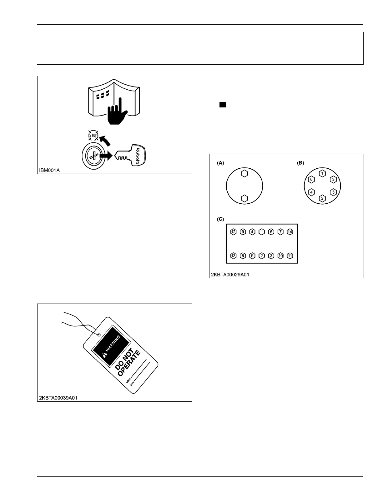
GENERAL WORKING PRECAUTIONS
V1505-CR-TE5
2-1
KiSC issued 03, 2022 A
1. Tightening bolts and nuts 2. GENERAL
GENERAL WORKING PRECAUTIONS
1. Tightening bolts and nuts
• T
ighten the bolts and nuts to their specified torque.
NOTE
• When servicing, observe the safety instructions in
the operator's manual and workshop manual.
Clean the machine before maintenance.
•
• Service the machine at a clean location.
• Park the machine on a stable and level ground then
lower the attachment to check the machine safely.
• Stop the engine and remove the key when leaving
the operator's seat for cleaning, maintenance, and
servicing.
• Before working, remove the negative (-) terminal
from the battery or turn off the battery isolator
switch.
• Whenever a special tool is required, use the special
tool that Kubota recommends.
• Use genuine Kubota parts to ensure safety and
machine performance.
– Tighten
top to bottom and left to right so the torque
is distributed evenly.
– Gradually tighten the bolts and nuts two or
three times.
(A) Alternately
(B) Diagonally
the bolts and nuts alternately from
Diagonally from center to
(C)
outside
• Hang a DO NOT OPERATE tag near the operator's
seat.
•
Observe workplace safety rules when performing
service and work.
2. Applying thread-locking fluid
1. Clean
fluid
moisture, oil, and dirt.
2. Apply the thread-locking fluid to the tip of the bolt.
3. If the threads are large, apply the thread-locking
fluid all around the bolt hole.
and dry the location where a thread-locking
will be applied with a solvent to remove
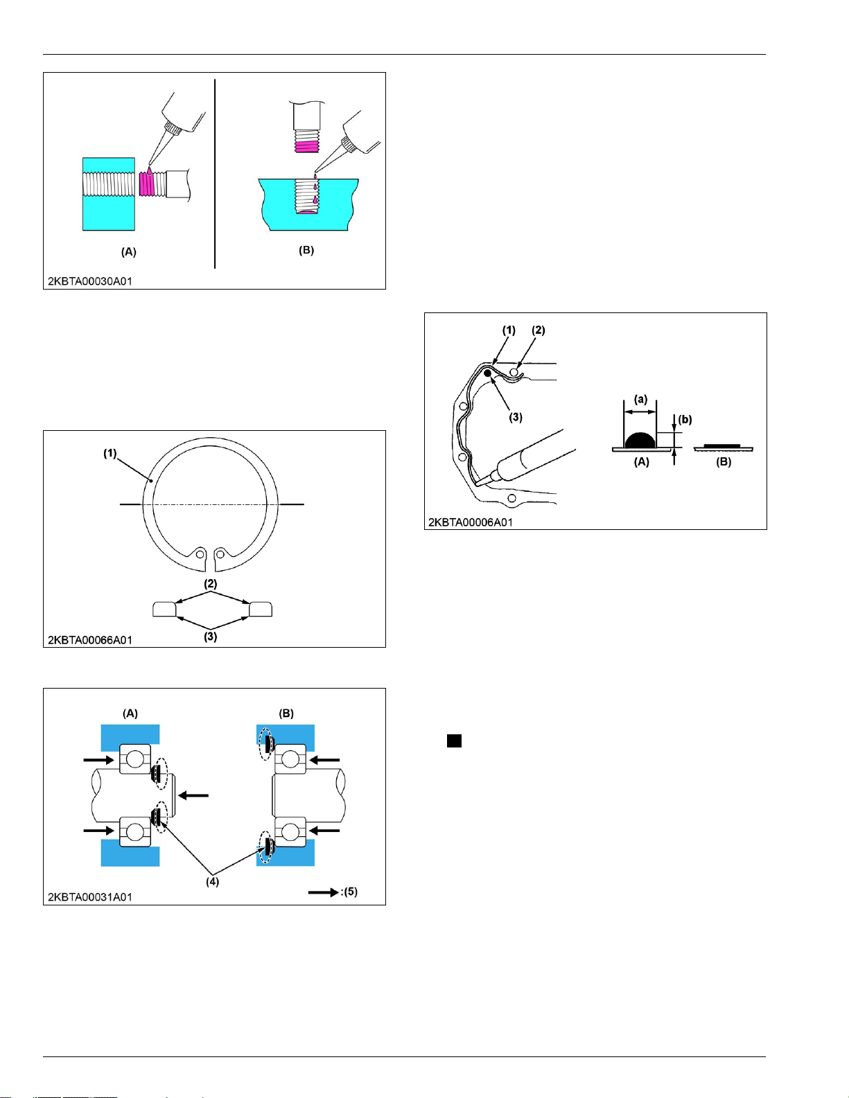
2. GENERAL
2-2
V1505-CR-TE5
KiSC issued 03, 2022 A
(A) Bolt hole (bolts, nuts) (B) Screw hole
3. Installing circlips
• When installing the circlip, assemble the circlip's
angular
(4) as shown in the figure.
side (3) toward the side that receives force
GENERAL WORKING PRECAUTIONS
3. Installing circlips
• When using liquid gasket, fully remove the old
gasket and grease or oil.
When applying liquid gasket, apply it on the joint
•
surface with a thickness of 3.0 to 5.0 mm (0.12 to
0.13 in.) without making any gaps.
• When applying liquid gasket near the bolt hole (2),
apply it in the inner side.
• If there is a risk of oil leakage or if the hole goes all
the way through when applying liquid gasket near
the dowel pin (3) hole, apply it in the inner side.
If there is no concern of oil leakage, apply it on the
outer side.
• Reassemble within 15 minutes after applying; wait
for 30 minutes or more then fill with oil.
(1) Circlip
(2) Rounded side
(4) Side that receives force
(5) Force
(3)
Angular side
External circlip
(A)
(B) Internal circlip
(1) Application route
(2) Bolt hole
Dowel pin
(3)
(A) Correct
(B) Incorrect
(a) 3.0 to 3.5 mm (0.12 to
0.13 in.)
(b) 3.0 to 5.0 mm (0.12 to
0.19 in.)
5. Replacing O-rings
1. Remove the burr and clean the O-ring groove.
the
2. Lubricate
the floating seal.
3. Put the O-ring in the groove.
NOTE
• Do not twist the O-ring.
• Remove the burr to avoid damage on the Oring caused by the burr.
O-ring. Do not apply any grease to
4. Handling liquid gasket
• Use the specified liquid gasket.
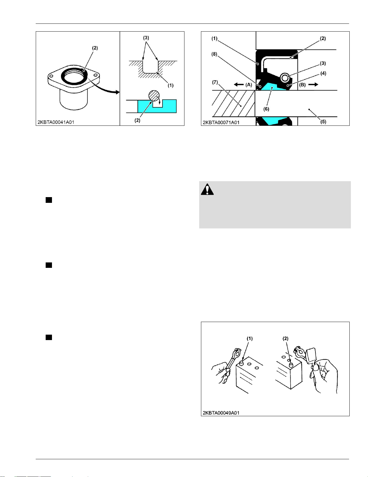
GENERAL WORKING PRECAUTIONS
V1505-CR-TE5
2-3
KiSC issued 03, 2022 A
6. Replacing oil seals 2. GENERAL
(1) O-ring groove
(2) O-ring
(3)
Burr
6. Replacing oil seals
there are burrs, scratches, or rust on the inner
1. If
surface
the surface of the shaft through which the oil seal
passes, remove it with sandpaper.
• If there
2. Clean the inner surface of the housing hole and the
surface of the shaft.
3. Lubricate the seal lip and dust lip.
• If the
• Use the specified grease or oil to lubricate
4. With the seal lip facing the airtight side (B) of the
object, use a press to press-fit the oil seal until it is
fixed to the boss.
of the housing hole, the chamfered part, or
NOTE
is a risk of splines or key grooves of
the shaft damaging the lip part of the seal,
wrap masking tape around those parts to
protect the seal.
NOTE
seal has a dust lip, grease the gap
between the lips to prevent dry wear that
occurs when the machine starts.
the lip.
(1) Packing
(2) Metal ring
Spring
(3)
(4) Seal lip
(5) Shaft
(6) Grease
(7) Masking tape
(8) Dust lip
(A) Air side
(B) Airtight side
7. Handling the battery
CAUTION
• When removing
negative (-) terminal first.
• When installing battery cables, connect positive
(+) terminal first.
• Do not install any battery with a capacity (Ah) other
than is specified.
• Securely attach the terminal covers on the cables
when connecting the cables to the battery terminal
posts. There is a danger of short-circuiting if the tip
of the cables attached to the battery terminal post is
exposed.
• Do not allow dirt and dust to collect on the battery.
• Connect the battery terminals after removing dust,
old grease, blue rust and others.
• Apply conductive grease thinly to the battery
terminal posts to prevent corrosion.
battery cables, disconnect
NOTE
• In cases
when installing an oil seal without a
press, place a wooden board on the seal
and gently tap the board with a hammer;
install the oil seal straightly and evenly.
(1) Battery negative (-) terminal (2) Battery positive (+) terminal
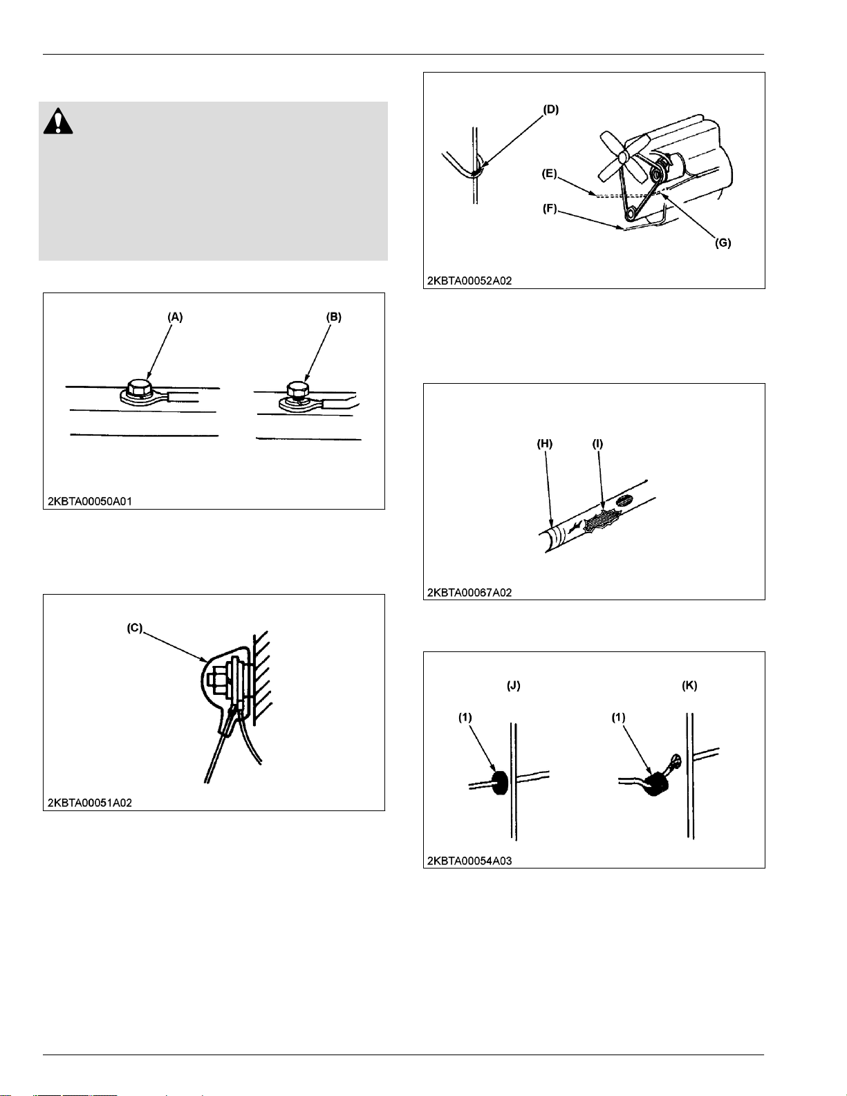
2. GENERAL
2-4
V1505-CR-TE5
KiSC issued 03, 2022 A
8. Handling wire harness
CAUTION
• Do not
in contact with other components.
• Do not clamp the wire harness to fuel hoses.
• If the wire harness is damaged, replace it
immediately with a new one.
• Do not alter the electrical device and wire
harness.
• Tighten the electrical terminals securely.
let an unprotected wire harness to come
GENERAL WORKING PRECAUTIONS
8. Handling wire harness
(A) Good (B) Bad: Loose bolt
• Check the electrical terminal protection and
clamping conditions before connecting the battery
cable.
(D) Hazardous position
(E) Wiring position: bad
(F)
Wiring position: good
• If
wire harness is damaged or degraded, replace
immediately
(H) Damaged (I) Torn
.
(G) Hazardous position
• Install the grommet securely.
(C) Covered completely with a
protection cover
• Keep
positions
sections.
the wire harness away from hazardous
such as rotating parts or high-temperature
(1) Grommet
(J) Good
Bad: poor installation
(K)
• Clamp the wire harness securely. Do not damage
the wire harness by the clamp.
•
Clamp the wire harness correctly. Do not slack,
twist, and pull.

GENERAL WORKING PRECAUTIONS
V1505-CR-TE5
2-5
KiSC issued 03, 2022 A
9. Handling fuses 2. GENERAL
10. Handling connectors
(2) Wire harness (3) Clamp
• Do not pinch the wire harness when installing parts.
• When disconnecting
the locking connectors, be
sure to disengage the lock before disconnecting.
There are two kinds of locks: one requires pressing
and the other requires pulling.
(A) Press
• Hold
on tightly to the connectors when
disconnecting them.
Do not pull wire harness itself.
•
(4) Wire harness (L) Bad
9. Handling fuses
• Always use fuses of the specified capacity.
• Do not use steel or copper wiring instead of fuse.
Do not install work light or radio without auxiliary
•
power line.
• Do not install auxiliaries to the fuses. The fuses
may blow.
(B) Correct method (C) Incorrect method
• Make sure the terminal condition of the connectors
is not bent, rusty
, and so on.
• If the terminal is rusted, remove rust with
sandpaper.
However, do not polish the terminal of the
waterproof connector or the plated terminal.
(1) Fuse
(2) Fusible link
(3)
Slow blow fuse
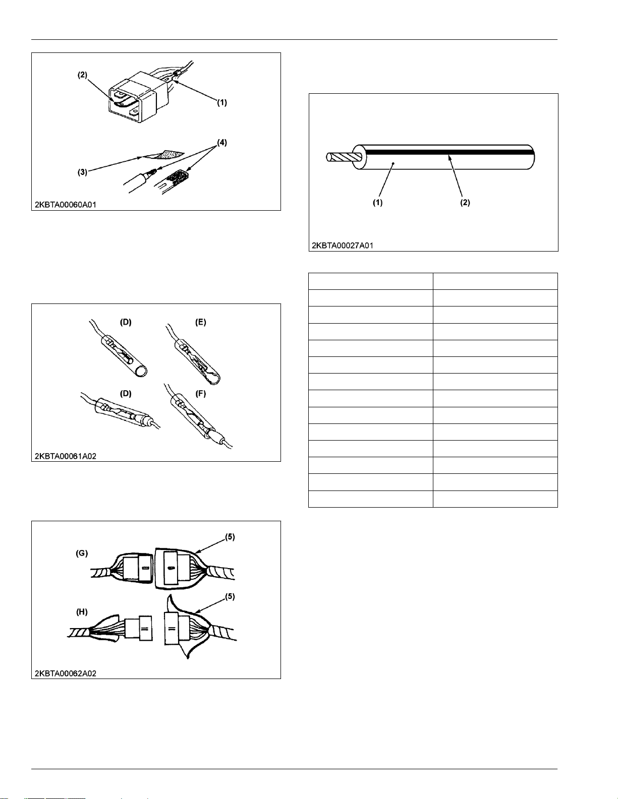
2. GENERAL
2-6
V1505-CR-TE5
KiSC issued 03, 2022 A
GENERAL WORKING PRECAUTIONS
11. Wiring color
11. Wiring color
• Wire colors are specified in the color codes.
(1) Missing terminal
(2) Bent terminal
(3)
Sandpaper
• Cover
the female bullet terminals and male bullet
(4) Rust
terminals securely with the plastic covers.
Make sure that the bullet terminals are secure and
•
connected securely to the tip.
(D) Good
(E) Bad: damaged cover
(F)
Bad: poor connection
• Cover the female connectors and male connectors
securely with the plastic covers.
(1) Wire color (2) Stripe
Wiring Colors Color code
Black B
Brown BR, Br
Green G
Gray GY, GR, Gr
Blue L
Light green LG, Lg
Orange OR, Or
Pink P
Purple PU, Pu, V
Red R
Sky blue SB, Sb
White W
Yellow Y
• This symbol of "/" shows color with stripe(s).
(An example)
W/R:
White with red stripe
(5) Cover
(G) Good
Bad: damaged cover
(H)
12. Dispose fluids correctly
• Do
not dispose fluids on the ground, down the
drain,
into a stream, pond, or lake. Obey related
environmental protection regulations when you
dispose of oil, fuel, coolant, electrolyte, and other
dangerous materials.
GENERAL WORKING PRECAUTIONS
V1505-CR-TE5
2-7
KiSC issued 03, 2022 A
2. GENERAL

2. GENERAL
2-8
V1505-CR-TE5
KiSC issued 03, 2022 A
GENERAL WORKING PRECAUTIONS
 Loading...