

Page 1

WORKSHOP MANUAL
KiSC issued 11, 2006 A
ROTARY MOWER
RCK54-24B-EC,RCK60-24B-EC,
RCK60-27B-ECRC60-24BR,
RC60-27BR
Page 2

TO THE READER
KiSC issued 11, 2006 A
This Workshop Manual has been prepared to provide servicing personnel with
information on the mechanism, service and maintenance of KUBOTA rotary mower
RCK54-24B-EC, RCK60-24 B-EC, RCK60-27 B-EC, RC60-24B R and RC60-27BR. It is
divided into two parts, “Mechanism” and “Servicing”
■ Mechanism
Information on the Fea tures and New Mec hanisms are d escribed. This in formation
should be understood before proceeding with troubleshooting, disassembling and
servicing.
■ Servicing
Under the heading “General” section comes general precautions, check and
maintenance and special tools. Other section, there are troubleshooting, servicing
specification lists, checking and adjusting, disassembling and assembling, and servicing
which cover procedures, pr ecauti ons , fac tor y spe cifi ca tion s and allowa bl e limits .
All information, illustrations and specifications contained in this manual are based on
the latest production information available at the time of publication.
The right is reserved to make changes in all information at any time without notice.
Due to covering many models o f this m anual , illu stration being used ha ve not bee n
specificated as one model.
© KUBOTA Corporation 2001
February 2001
Page 3
RCK54/60-24B-EC · RCK60-27B-EC · RC60-24/27BR, WSM
SAFETY FIRST
KiSC issued 11, 2006 A
SAFETY INSTRUCTIONS
SAFETY INSTRUCTIONS
This symbol, the industry’s “Safety Alert Symbol”, is used throughout this manual and on labels on
the machine itself to warn of the possibility of personal injury. Read these instructions carefully.
It is essential that you read the instructions and safety regulations before you attempt to repair or use
this unit.
DANGER : Indicates an imminently hazardous situation which, if not avoided, will result in
death or serious injury.
WARNING : Indicates a potentially hazardous situation which, if not avoided, could result in
death or serious injury.
CAUTION : Indicates a potentially hazardous situation which, if not avoided, may result in
minor or moderate injury.
■ IMPORTANT : Indicates that equipment or property damage could result if instructions are not
followed.
■ NOTE : Gives helpful information.
BEFORE SERVICING AND REPAIRING
• Read all instructions and safety instructions in this
manual and on your machine safety decals.
• Clean the work area and machine.
• Park the machine on a firm and level ground, and set
the parking brake.
• Lower the implement to the ground.
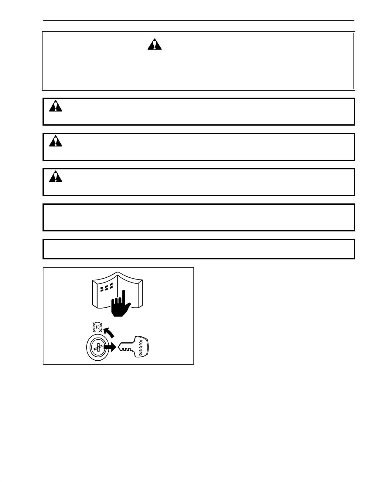
• Stop the engine, and remove the key.
• Disconnect the battery negative cable.
• Hang a “DO NOT OPERATE” tag in operator
station.
1
Page 4

RCK54/60-24B-EC · RCK60-27B-EC · RC60-24/27BR, WSM
KiSC issued 11, 2006 A
SAFETY INSTRUCTIONS
SAFETY STARTING
• Do not start the engine by shorting across starter
terminals or bypassing the safety start switch.
• Do not alter or remove any part of machine safety
system.
• Before starting the engine, make sure that all shift
levers are in neutral positions or in disengaged
positions.
• Never start the engine while standing on ground.
Start the engine only from operator’s seat.
SAFETY WORKING
• Do not work on the machine while under the influence
of alcohol, medication , or other substances or while
fatigued.
• Wear close fitting clothing and safety equipment
appropriate to the job.
• Use tools appropriate to the work. Markshift tools,
parts, and procedures are not recommended.
• When servicing is performed together by two or more
persons, take care to perform all work safely.
• Do not work under the machine that is supported
solely by a jack. Always support the machine by
safety stands.
• Do not touch the rotating or hot parts while the engine
is running.
• Never remove the radiator cap while the engine is
running, or immediately after stopping. Otherwise, hot
water will spout out from radiator. Only remove
radiator cap when cool enough to touch with bare
hands. Slowly loosen the cap to first stop to relieve
pressure before removing completely.
• Escaping fluid (fuel or hydraulic oil) un der pressure
can penetrate the skin causing serious injury. Relieve
pressure before disconnecting hydraulic or fuel lines.
Tighten all connections before applying pressure.
AVOID FIRES
• Fuel is extremely flammable and explosive under
certain conditions. Do not smoke or allow flames or
sparks in your working area.
• To avoid sparks from an accidental short circuit,
always disconnect the battery negative cable first and
connect it last.
• Battery gas can explode. Keep sparks and open
flame away from the top of b attery, especially when
charging the battery.
• Mark sure that no fuel has been spilled on the engine.
2
Page 5
RCK54/60-24B-EC · RCK60-27B-EC · RC60-24/27BR, WSM
KiSC issued 11, 2006 A
SAFETY INSTRUCTIONS
VENTILATE WORK AREA
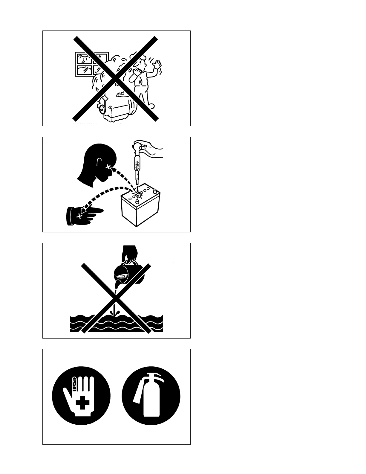
• If the engine must be running to do some work, make
sure the area is well ventilated . Neve r run the eng ine
in a closed area. The exhaust gas contains poisonous
carbon monoxide.
PREVENT ACID BURNS
• Sulfuric acid in batte ry electrolyte is poisonou s. It is
strong enough to burn skin, clothing and cause
blindness if splashed into eyes. Keep electrolyte
away from eyes, hands and clothing. If you spill
electrolyte on yourself, flush with water, and get
medical attention immediately.
DISPOSE OF FLUIDS PROPERLY
• Do not pour fluids into the ground, down a drain, or
into a stream, pond, or lake. Observe relevant
environmental prot ectio n regulati ons whe n disp osing
of oil, fuel, coolant, electrolyte and other harmful
waste.
PREPARE FOR EMERGENCIES
• Keep a first aid kit and fire extingui sher handy at all
times.
• Keep emergency numbers for doctors, ambulance
service, hospital and fire department near your
telephone.
3
Page 6

RCK54/60-24B-EC · RCK60-27B-EC · RC60-24/27BR, WSM
KiSC issued 11, 2006 A
SAFETY INSTRUCTIONS
SAFETY DECALS
The following safety decals are installed on the mower.
If a decal becomes damaged, illegible or is not on the mower, replace it. The decal part number is listed in
the parts list.
4
Page 7

RCK54/60-24B-EC · RCK60-27B-EC · RC60-24/27BR, WSM
KiSC issued 11, 2006 A
SAFETY INSTRUCTIONS
CARE OF DANGER, WARNING AND CAUTION LABELS
1. Keep danger, warning and caution labels clean and free from obstructing material.
2. Clean danger, warning and caution labels with soap and water, dry with a soft cloth.
3. Replace damaged or missing danger, warning and caution labels with new labels from your KUBOTA
Distributor.
4. If a component with danger, warning or caution label(s) affixed is replaced with new part, make sure the
label(s) is (are) attached in the same location (s) as the replaced component.
5. Mount new danger, warning and caution labels by applying on a clean dry surface and pressing any
bubbles to outside edge.
ENTRETIEN DES ETIQUETTES DE DANGER, D’AVERTISSEMENT ET D’ATTENTION
1. Conserver les étiquettes de danger, d’avertissement et d’attention propres et exemptes d’un matériel
d’obstruction.
2. Nettoyer les étiquettes de danger, d’avertissement et d’attention avec de l’eau et du savon, puis les essuyer
avec un tissu doux.
3. Remplacer les étiquettes de danger, d’avertissement et d’attention endommagées ou manquantes p ar des
étiquettes neuves de chez votre distributeur KUBOTA.
4. Si un élément mentionné par des étiquettes de danger, d’avertissement ou d’attention est remplacé par une
pièce neuve, s’assurer que les étiquettes soient placées au(x) même(s) endroit(s) que l’élément remplacé.
5. Placer une étiquette neuve de danger , d’avertissemant ou d’attention en l’appliquant sur une surface sèche
et propre et en appuyant dessus pour y éliminer vers le bord extérieur les bulles d’air qui peuvent s’ y
trouver.
ACHTEN SIE AUF DIE ERHALTUNG DER WARN- UND HINWEIS-AUFKLEBER
1. Die Warn- und Hinweis- Aufkleber sauber und lesbar halten.
2. Die Aufkleber mit Seife und Wasser waschen und sie mit einem weichen Tuch abtrocknen.
3. Beschädigte oder verlorengegangene Aufkleber durch neue Original-Schilder von lhrem KUBOTA Verteiler
ersetzen.
4. Falls ein Bauteil mit Warn- und / oder Hinweis-Aufklebern durch ein Neuteil ersetzt wurde, darauf achten,
daß das Neuteil die gleichen Aufkleber besitzt oder erhält.
5. Beim Erneuern von Aufklebern darauf achten, daß der Untergrund sauber, trocken und fettfrei ist. Etwaige
Blasen nach außen drücken.
5
Page 8

RCK54/60-24B-EC · RCK60-27B-EC · RC60-24/27BR, WSM
KiSC issued 11, 2006 A
TERMINOLOGY
TERMINOLOGY
(1) Front Gauge Wheel
(2) Belt Cover (Left)
(3) Gear Box
(4) Belt Cover (Right)
(5) Discharge Chute
(6) Deck
(7) Universal Joint
(8) Outer Blade
(9) Front Anti-scalp Roller
(10) Center Blade
(11) Outer Blade
6
(12) Rear Anti-scalp Roller
(13) Rear Gauge Wheel
(14) Anti-scalp Wh eel
Page 9
RCK54/60-24B-EC · RCK60-27B-EC · RC60-24/27BR, WSM
KiSC issued 11, 2006 A
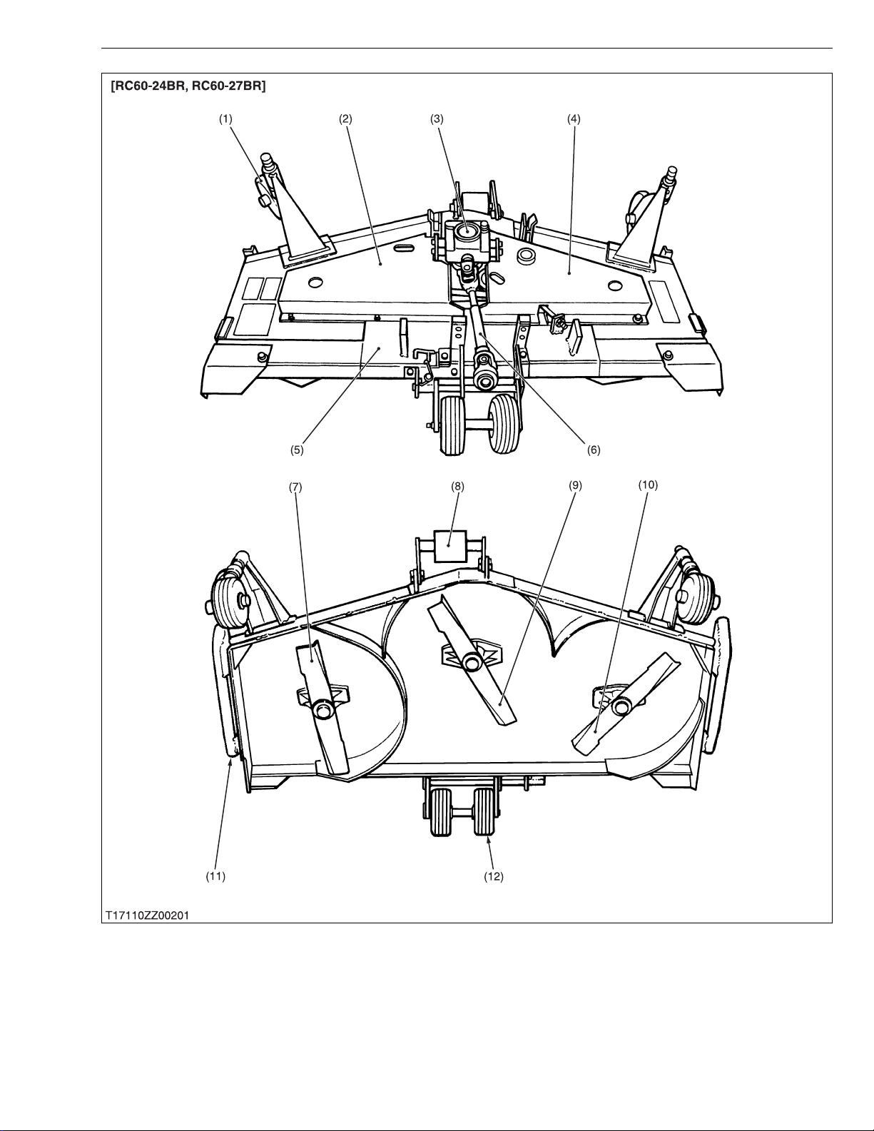
TERMINOLOGY
(1) Front Gauge Wheel
(2) Belt Cover (Left)
(3) Gear Box
(4) Belt Cover (Right)
(5) Deck
(6) Universal Joint
(7) Outer Blade
(8) Front Anti-scalp Roller
(9) Center Blade
7
(10) Outer Blade
(11) Skid
(12) Rear Gauge Wheel
Page 10

RCK54/60-24B-EC · RCK60-27B-EC · RC60-24/27BR, WSM
KiSC issued 11, 2006 A
SPECIFICATIONS
SPECIFICATIONS
Model RCK54-24B-EC RCK60-24B-EC
RCK60-27B-EC
Suitable tractor B1710, B2110, B2410 B2710
Type Side discharge rotary mower
Mounting method Parallel linkage
Adjustment of cutting height Gauge wheel
Cutting width 1372 mm (54 in.) 1524 mm (60 in.)
Cutting height 38 to 102 mm (1.5 to 4.0 in.)
Weight (Approx.) 156 kg (344 lbs) 158 kg (348 lbs)
Blade spindle speed 50.0 r/s (3000 rpm) 44.7 r/s (2680 rpm)
Blade tip velocity 74.6 m/s (14680 fpm) 73.4 m/s (14439 fpm)
Blade length 475 mm (18.7 in.) 523 mm (20.6 in.)
Number of blades 3
Total length 1072 mm (42.2 in) 1100 mm (43.3 in.) 1060 mm (41.7 in.)
Dimensions
Total width 1695 mm (66.7 in.) 1881 mm (74.0 in.)
Total height 345 mm (13.6 in.)
Model RCK60-24BR RC60-27BR
Suitable tractor B1710, B2110, B2410 B2710
Type Rear discharge rotary mower
Mounting method Parallel linkage
Adjustment of cutting height Gauge wheel
Cutting width 1524 mm (60 in.)
Cutting height 25 to 89 mm (1.0 to 3.5 in.)
Weight (Approx.) 154 kg (336 lbs) 158 kg (348 lbs)
Blade spindle speed 49.5 r/s (2970 rpm)
Blade tip velocity 81.3 m/s (15995 fpm)
Blade length 520 mm (20.5 in.)
Number of blades 3
Total length 1122 mm (44.2 in) 1175 mm (46.3 in.)
Dimensions
Total width 1613 mm (63.5 in.)
Total height 348 mm (13.7 in.)
W1027634
W1028910
8
Page 11

GENERAL
KiSC issued 11, 2006 A
CONTENTS
1. MOWER IDENTIFICATION............................................................................. G-1
2. GENERAL PRECAUTION .............................................................................. G-2
3. LUBRICANTS .................................................................................................. G-3
4. TIGHTENING TORQUES (GENERAL USE SCREWS, BOLTS AND
NUTS) .............................................................................................................. G-4
5. MAINTENANCE CHECK LIST....................................................................... G-5
6. CHECK AND MAINTENANCE......... ...... ...... ....... ...... ....... ...... ....... ................. G-6
[1] CHECK POINTS OF DAILY OR EACH USE....................................... G-6
[2] CHECK POINT OF INITIAL 50 HOURS ............................................... G-9
[3] CHECK POINTS OF EVERY 50 HOURS........................................... G-10
[4] CHECK POINT OF EVERY 150 HOURS ........................................... G-11
[5] CHECK POINT OF EVERY 2 YEARS................................................ G-11
7. SETTING UP MOWER ................................................................................ G-12
Page 12
RCK54/60-24B-EC · RCK60-27B-EC · RC60-24/27BR, WSM
KiSC issued 11, 2006 A
1. MOWER IDENTIFICATION
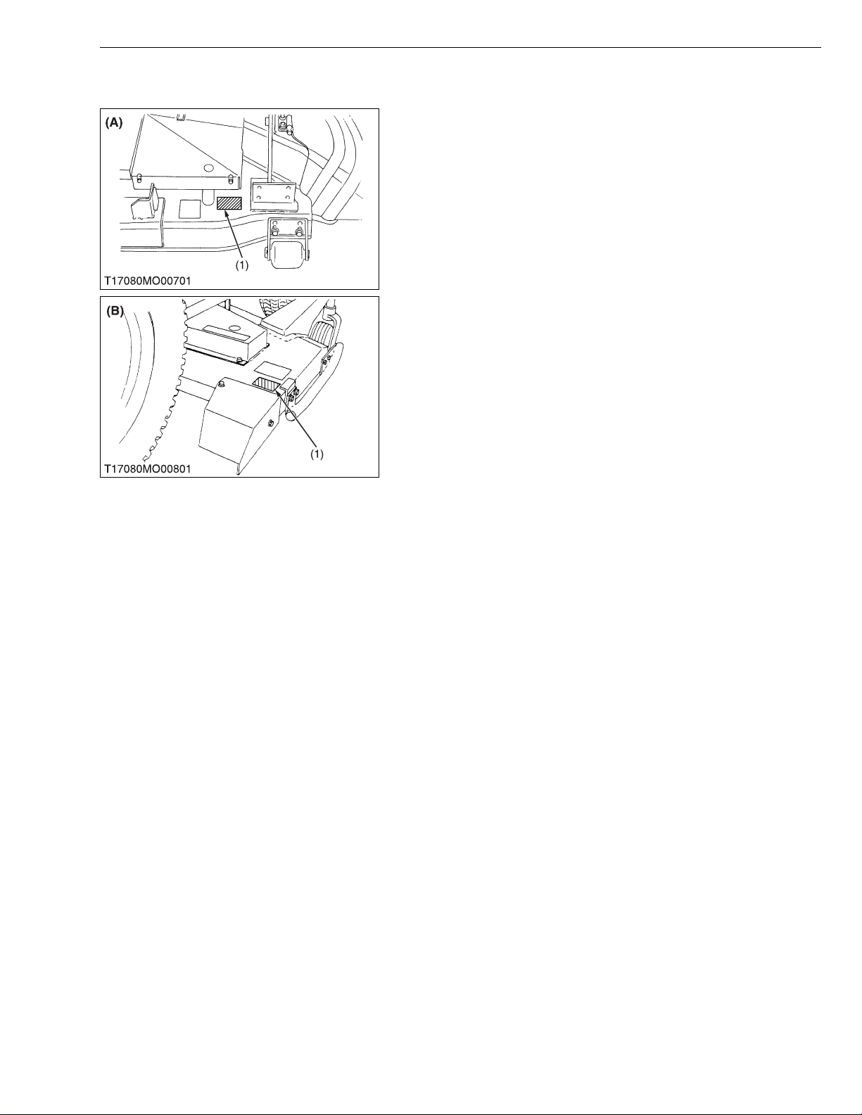
When contacting your loca l KUBOTA distr ibutor, alway s specify
mower serial number.
(1) Mower Serial Number (A) RCK54-24B-EC, RCK60-24B-EC,
G GENERAL
RCK60-27B-EC
(B) RC60-24BR, RC60-27BR
W1020623
G-1
Page 13

RCK54/60-24B-EC · RCK60-27B-EC · RC60-24/27BR, WSM
KiSC issued 11, 2006 A
2. GENERAL PRECAUTION
• During disa ssembly, ca refully ar range removed parts in a cle an
area to prevent confusion later. Screws, bolts and nuts should be
installed in their original position to prevent reassembly errors.
• When special tools are requi red, use KUBOT A genuine speci al
tools. Special tools which are not frequently used should be
made according to the drawings provided.
• Use KUBOTA genuine parts or KUBOTA-recommended parts
and lubricants or their equivalents.
• Gaskets and o-rings must be replaced during reassembly.
• Apply grease to new o-rings or oil seals before assembling. See
the figure.
• When reassem bling external snap rings or inte rnal snap rings,
they must be positioned so that sharp edge faces against the
direction from which a force is applied. See the figure.
• Metric screws, bolts and nuts are not interchangeable with
nonmetric fasteners.
• Remove oil and dirt from parts before measuring.
(1) Grease
(2) Force
(3) Sharp Edge
G GENERAL
(A) Oil Seal
(B) External Snap Ring
(C) Internal Snap Ring
W1020761
G-2
Page 14

RCK54/60-24B-EC · RCK60-27B-EC · RC60-24/27BR, WSM
KiSC issued 11, 2006 A
3. LUBRICANTS
No. Place Capacity Lubricants
1 Gear Box
2 Universal joint
Spindle shafts
3
(Bevel gear shaft and blade shafts)
4 Belt tension pulley
5 Belt tension pivot
6Life arms
7 Front gauge wheels
8 Rear gauge wheels
9 Front center anti-scalp roller
Middle lift arm (B1710, B2110,
10
B2410 with lift cylinder type)
Lift cylinder joint pin
11
(with lift cylinder type)
0.36 L
0.38 U.S.qts.
0.32 lmp.qts.
Greasing
Until grease overflows SAE multi-purpose type grease
SAE 90 gear oil
(API Service GL-5 gear oil)
G GENERAL
G-3
Page 15

RCK54/60-24B-EC · RCK60-27B-EC · RC60-24/27BR, WSM
KiSC issued 11, 2006 A
G GENERAL
4. TIGHTENING TORQUES (GENERAL USE SCREWS,
BOLTS AND NUTS)
Screws, bolts and nuts whos e tightening torques are not spec ified i n this W orkshop Ma nual sho uld be tig htened
according to the table below.
Indication on top of
bolt
Material of bolt SS400, S20C S43C, S48C
Material of opponent
part
Unit
Diameter
M6
(6 mm, 0.24 in.)
M8
(8 mm, 0.31 in.)
M10
(10 mm, 0.39 in.)
M12
(12 mm, 0.47 in.)
M14
(14 mm, 0.55 in.)
M16
(16 mm, 0.63 in.)
M18
(18 mm, 0.71 in.)
M20
(20 mm, 0.79 in.)
No-grade or 4T 7T 9T
SCr435,
SCM435
Ordinariness Aluminum Ordinariness Aluminum Ordinariness
N·m kgf·m ft-lbs N·m kgf·m ft-lbs N·m kgf·m ft-lbs N·m kgf·m ft-lbs N·m kgf·m ft-lbs
7.85
0.80
5.79
7.85
0.80
5.79
9.81
1.00
7.24
7.85
0.80
5.79
12.3
to
9.31
17.7
to
20.5
39.3
to
45.1
62.8
to
72.5
108
to
125
167
to
191
246
to
284
334
to
392
to
0.95
1.8
to
2.1
4.0
to
4.6
6.4
to
7.4
11.0
to
12.8
17.0
to
19.5
25.0
to
29.0
34.0
to
40.0
to
6.87
13.1
to
15.1
29.0
to
33.2
46.3
to
53.5
79.6
to
92.5
123
to
141
181
to
209
246
to
289
to
to
8.82
0.90
16.7
19.6
31.4
34.3
1.7
to
2.0
3.2
to
3.5
–––
–––
–––
–––
–––
to
6.50
12.3
to
to
14.4
23.2
to
to
25.3
to
11.2
23.6
to
27.4
48.1
to
55.8
77.5
to
90.2
124
to
147
197
to
225
275
to
318
368
to
431
to
1.15
2.4
to
2.8
4.9
to
5.7
7.9
to
9.2
12.6
to
15.0
20.0
to
23.0
28.0
to
32.5
37.5
to
44.0
to
8.31
17.4
to
20.2
35.5
to
41.2
57.2
to
66.5
91.2
to
108
145
to
166
203
to
235
272
to
318
to
to
8.82
0.90
17.7
20.5
39.3
44.1
62.8
72.5
1.8
to
2.1
4.0
to
4.5
6.4
to
7.4
–––
–––
–––
–––
to
6.50
13.1
to
to
15.1
29.0
to
to
32.5
46.3
to
to
53.5
to
14.2
29.5
to
34.3
60.9
to
70.6
103
to
117
167
to
196
260
to
304
344
to
402
491
to
568
1.25
to
1.45
3.0
to
3.5
6.2
to
7.2
10.5
to
12.0
17.0
to
20.0
26.5
to
31.0
35.0
to
41.0
50.0
to
58.0
W1034542
9.05
to
10.4
21.7
to
25.3
44.9
to
52.0
76.0
to
86.7
123
to
144
192
to
224
254
to
296
362
to
419
Grade
Unit
Nominal Diameter
5/16 23.1 to 27.8 2.35 to 2.84 17.0 to 20.5 32.5 to 39.3 3.31 to 4.01 24.0 to 29.0
3/8 47.5 to 57.0 4.84 to 5.82 35.0 to 42.0 61.0 to 73.2 6.22 to 7.47 45.0 to 54.0
1/2 108.5 to 130.2 11.07 to 13.29 80.0 to 96.0 149.2 to 179.0 15.22 to 18.27 110.0 to 132.0
9/16 149.2 to 179.0 15.22 to 18.27 110.0 to 132.0 217.0 to 260.4 22.14 to 26.57 160.0 to 192.0
5/8 203.4 to 244.1 20.75 to 24.91 150.0 to 180.0 298.3 to 358.0 30.44 to 36.53 220.0 to 264.0
SAE GR.5 SAE GR.8
N·m kgf·m ft-lbs N·m kgf·m ft-lbs
W1022485
G-4
Page 16

RCK54/60-24B-EC · RCK60-27B-EC · RC60-24/27BR, WSM
KiSC issued 11, 2006 A
G GENERAL
5. MAINTENANCE CHECK LIST
To keep the mow er working in good c ondition as well as to avoid any accident and trouble, carry out peri odic
inspection and maintenance. Check the following points before use.
Service interval Check points
Daily (Each use) • Anything unusual in previous day’s operation
• Make sure mower blade screws are tighten
• Check mower blades for wear or damage
• Check gear box oil level
• Check oil leaks
• Check all hardware
• Make sure all pins are in place
• Clean mower deck
• Apply grease to universal joint
• Apply grease to spindle shafts (Bevel gear shaft and blade shafts)
• Apply grease to belt tension pulley
• Apply grease to belt tension pivot
• Apply grease to front center anti-scalp roller
• Apply grease to lift arms
Initial 50 hours • Change gear box oil G-9
Every 50 hours • Apply grease to front and rear gauge wheels
• Apply grease to middle lift arm
• Apply grease to lift cylinder joint pin
• Check mower belt
Every 150 hours • Change gear box oil G-9
Every 2 years
(After purchase)
• Replace gear box oil seal G-11
Reference
Page
–
G-6
S-4
G-7
–
–
–
–
G-8
G-8
G-8
G-8
G-10
G-8, 10
G-10
G-10
G-10
S-4
W1013580
G-5
Page 17

RCK54/60-24B-EC · RCK60-27B-EC · RC60-24/27BR, WSM
NOTE■
KiSC issued 11, 2006 A
6. CHECK AND MAINTENANCE
[1] CHECK POINTS OF DAILY OR EACH USE
Retightening Mower Blade Screw
CAUTION
• To avoid injury, always handle the mower blade with care.
1. Dismount the mower and turn it over to expose the mower
blades.
2. Wedge a block of wood securely bet ween the mower b lade a nd
mower deck.
3. Retighten the mower blade screw to the specified torque.
4. If the mower blade screw is worn or broken, replace it.
• The RC60-24BR and RC60-27BR mower blade screw has
left-hand threads.
Turn it counterclockwise to tighten.
Tightening torque Mower blade screw
G GENERAL
98.1 to 117.1 N·m
10.0 to 12.0 kgf·m
72.3 to 86.8 ft-lbs
(1) Mower Blade Screw (A) RCK54-24B-EC, RCK60-24B-EC,
RCK60-27B-EC
(B) RC60-24BR, RC60-27BR
W1025290
Checking Mower Blade
1. See page S-4.
W1025440
G-6
Page 18

RCK54/60-24B-EC · RCK60-27B-EC · RC60-24/27BR, WSM
IMPORTANT■
KiSC issued 11, 2006 A
G GENERAL
Checking Gear Box Oil Level
1. Place the mower on level ground.
2. Loosen the check plug (2), and check to see if oil seems from the
opening.
3. If the oil lev el is low, remove the oil fille r plug (1) and a dd new
gear oil.
• Use the specified gear oil.
Refer to “LUBRICANTS”. (See page G-3.)
(1) Oil Filler Plug
(2) Check Plug
(3) Drain Plug
(A) RCK54-27B-EC, RCK60-24B-EC
(B) RCK60-27B-EC
(C) RC60-24BR, RC60-27BR
W1025491
G-7
Page 19

RCK54/60-24B-EC · RCK60-27B-EC · RC60-24/27BR, WSM
KiSC issued 11, 2006 A
G GENERAL
Greasing
1. Apply grease to the following points as figures.
(1) Bevel Gear Shaft
(2) Blade Shaft
(3) Belt Tension Pulley
(4) Belt Tension Pivot
(5) Lift Arm
(6) Spline of Universal Joint
(7) Universal Joint
G-8
(A) RCK54-24B-EC, RCK60-24B-EC,
RCK60-27B-EC
(B) RC60-24BR, RC60-27BR
Page 20

RCK54/60-24B-EC · RCK60-27B-EC · RC60-24/27BR, WSM
IMPORTANT■
KiSC issued 11, 2006 A
[2] CHECK POINT OF INITIAL 50 HOURS
Changing Gear Box Oil
1. Dismount the mower from the trac tor, and place the mower on
level ground.
2. Remove the oil filler plug (1).
3. Remove the drain plug (3), and drain the used oil completely.
4. After draining the used oil, reinstall the drain plug.
5. Fill with new oil up to the specified level.
• Use the specified gear oil.
Refer to “LUBRICANTS”. (See page G-3.)
(1) Oil Filler Plug
(2) Check Plug
(3) Drain Plug
G GENERAL
(A) RCK54-24B-EC, RCK60-24B-EC
(B) RCK60-27B-EC
(C) RC60-24BR, RC60-27BR
W1028353
G-9
Page 21

RCK54/60-24B-EC · RCK60-27B-EC · RC60-24/27BR, WSM
KiSC issued 11, 2006 A
[3] CHECK POINTS OF EVERY 50 HOURS
Greasing
1. Apply grease to the following position as figures.
G GENERAL
(1) Front Gauge Wheel Bracket
(2) Front Wheel
(3) Rear Wheel
(4) Middle Lift Arm
(5) Lift Arm
(6) Lift Cylinder Joint Pin
(7) Front Center Anti-scalp Roller
(A) RCK54-24B-EC, RCK60-24B-EC,
RCK60-27B-EC
(B) RC60-24BR, RC60-27BR
(C) B1710, B2110, B2410 with Lift
Cylinder Type
(D) Lift Cylinder Type
W1014935
Checking Mower Belt
1. See page S-4.
W1028893
G-10
Page 22
RCK54/60-24B-EC · RCK60-27B-EC · RC60-24/27BR, WSM
KiSC issued 11, 2006 A
[4] CHECK POINT OF EVERY 150 HOURS
Changing Gear Box Oil
1. See page G-9.
[5] CHECK POINT OF EVERY 2 YEARS
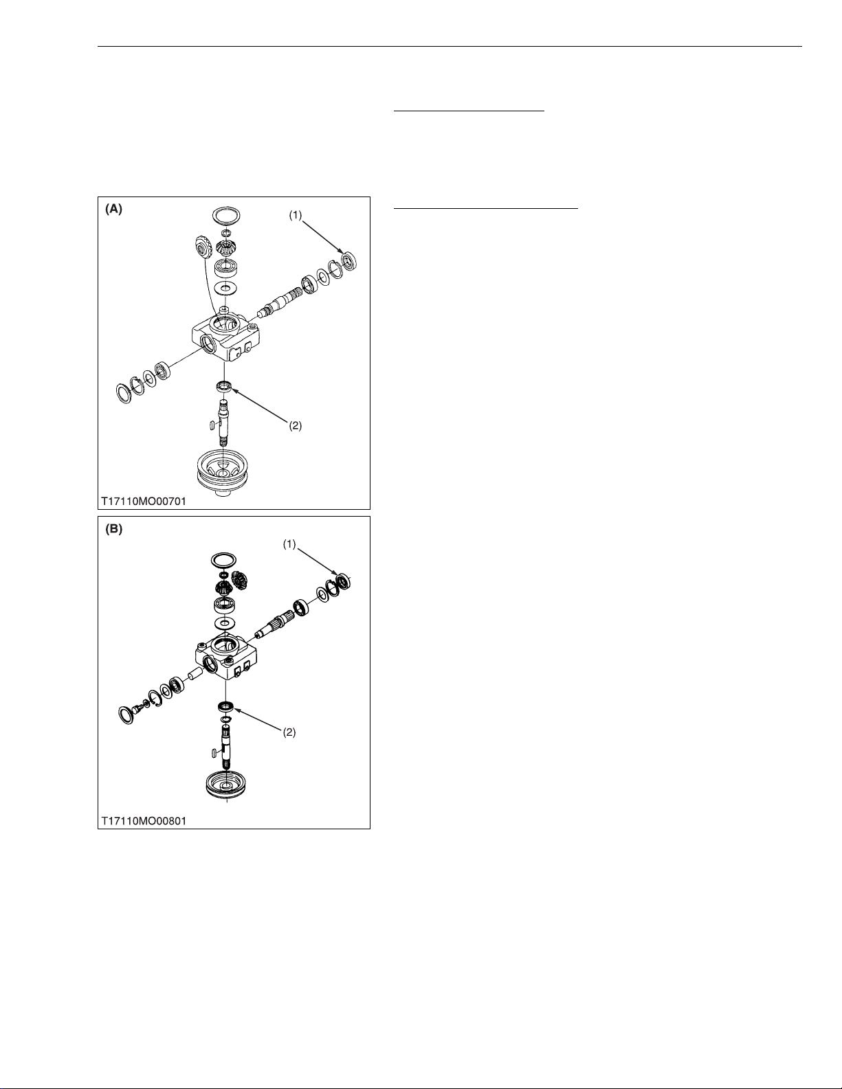
Replacing Gear Box Oil Seal
1. Replace the gear box oil seals (1), (2) with new ones. (See page
S-8, 13.)
(1) Oil Seal
(2) Oil Seal
G GENERAL
W1029013
(A) RCK54-24B-EC, RCK60-24B-EC,
RCK60-27B-EC
(B) RC60-24BR, RC60-27BR
W1029072
G-11
Page 23

RCK54/60-24B-EC · RCK60-27B-EC · RC60-24/27BR, WSM
KiSC issued 11, 2006 A
7. SETTING UP MOWER
G GENERAL
Assembling Mower
CAUTION
• Do not operate the rear gauge wheel adjusting lever (4)
without support by block (3).
1. Take out all mower components from the case, and assemble the
mower.
2. Support the mower deck with a block (3) as shown in the figure.
3. Turn the an ti-scalp whee l (1) sidewa y position, and set the rear
gauge wheel (2) on the lowest cutting height.
4. Remove the block.
(1) Anti-scalp Wheel
(2) Rear Gauge Wheel
(3) Block
(4) Rear Gauge Wheel Adjusting Lever
W1029213
Rear Wheel (RCK54-24B-EC, RCK60-24B-EC, RC60-24BR)
1. Park the tractor on level ground, and set the both rear wheels (1)
of the tractor at the outer position (A).
(1) Rear Wheel A : Outer Position
W1015453
Front Hanger Bracket
1. Attach the front hanger bracket (1) to the frame with M14 bolts.
(1) Front Hanger Bracket
W1029353
G-12
Page 24

RCK54/60-24B-EC · RCK60-27B-EC · RC60-24/27BR, WSM
KiSC issued 11, 2006 A
G GENERAL
Mid Hanger Bracket
1. Screw M12 stud bolts (1) in the clutch housing.
2. Attach the mid hanger brackets (2) to the clutch housing with
spring washers and nuts.
31.4 N·m
Stud bolt
Tightening torque
Nut
3.2 kgf·m
23.1 ft-lb s
68.6 N·m
7.0 kgf·m
50.6 ft-lb s
(1) Stud Bolt
(2) Mid Hanger Bracket
(A) Outside (Round End)
(B) Inside (Flat End)
(C) Thread Size : M12 x Pitch 1.25
(D) Thread Size : M12 x Pitch 1.75
(E) RCK54-24B-EC, RCK60-24B-EC,
RC60-24BR
(F) RCK60-27B-EC, RC60-27BR
W1029421
Rear Hanger Bracket (Lift Cylinder Type)
■ B1710, B2110 and B2410
1. Assemble the lift cylinder kit as shown in figu re .
2. Apply grease to the cylinder joint pin (4), (5) and lift shaft (1).
3. Apply seal tape to the cylinde r adaptor (2 ) and set the direction
as shown in figure.
Tighten the cylinder adaptor with specified torque then rotate
(clockwise) the adaptor to set the specified direction.
4. Set the cylinder rod flat face toward the RH side of machine.
Tightening torque Cylinder adaptor
24.5 N·m
2.5 kgf·m
18.1 ft-lb s
(1) Lift Shaft
(2) Cylinder Adaptor
(3) Cylinder
(4) Joint Pin
(5) Joint Pin
G-13
A : 1.57 rad. (90 °)
W1015981
Page 25

RCK54/60-24B-EC · RCK60-27B-EC · RC60-24/27BR, WSM
KiSC issued 11, 2006 A
G GENERAL
■ B2710
1. Assemble the lift cylinder kit as shown in figure.
2. Apply grease to the cylinder joint pin (2) and (3).
3. Apply seal tap e to the cyl inder adaptor ( 4) and set the direction
as shown in figure.
Tighten the cylinder adaptor with specified torque then rotate
(clockwise) the adaptor to set the specified direction.
4. Assemble the middle lift arm (1) as shown in figure, smaller
clearance toward the RH side of machine.
5. Set the cylinder rod flat face toward the RH side of machine.
Cylinder adaptor
Tightening torque
Holder mounting reamer
screw
24.5 N·m
2.5 kgf·m
18.1 ft-lbs
48.1 to 55.8 N·m
4.9 to 5.7 kgf·m
35.5 to 41.2 ft-lbs
(1) Middle Lift Arm
(2) Joint Pin
(3) Joint Pin
(4) Cylinder Adaptor
(5) Cylinder
(6) Holder
(7) Cylinder Rod
(8) Holder Mounting Reamer Screw
A : Clearance 2.0 mm (0.078 in.)
B : Clearance 10.0 mm (0.394 in.)
C : 0.35 to 0.70 rad. (20 to 40 °)
W1016196
G-14
Page 26
RCK54/60-24B-EC · RCK60-27B-EC · RC60-24/27BR, WSM
KiSC issued 11, 2006 A
G GENERAL
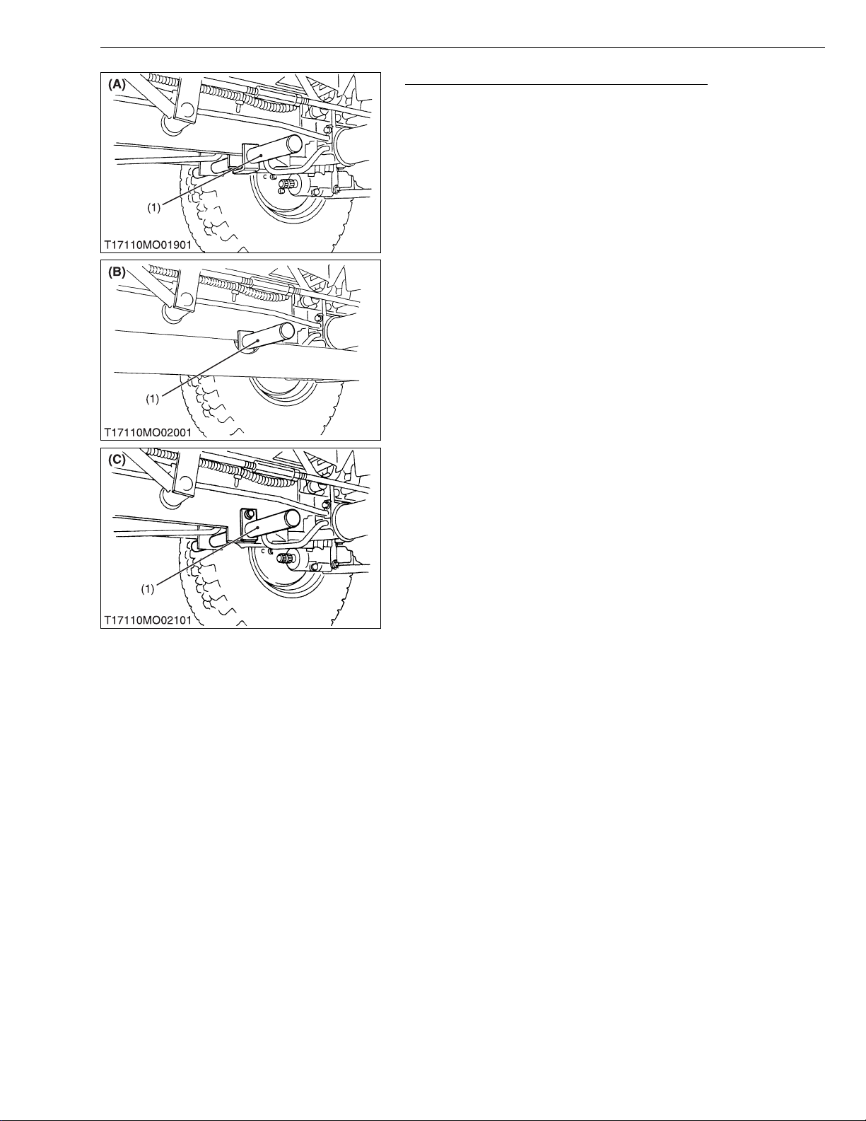
Rear Hanger Bracket (3-Point Hitch Lift Type)
1. Insert the rear hanger bracket (1) from left side of the frame
holes, and set it with M8 bolt.
(1) Rear Hanger Bracket (A) RCK 54-24B-E C, RCK60-24B-EC
(B) RCK60-27B-EC
(C) RC60-24BR, RC60-27BR
W1016620
G-15
Page 27

RCK54/60-24B-EC · RCK60-27B-EC · RC60-24/27BR, WSM
NOTE■
KiSC issued 11, 2006 A
G GENERAL
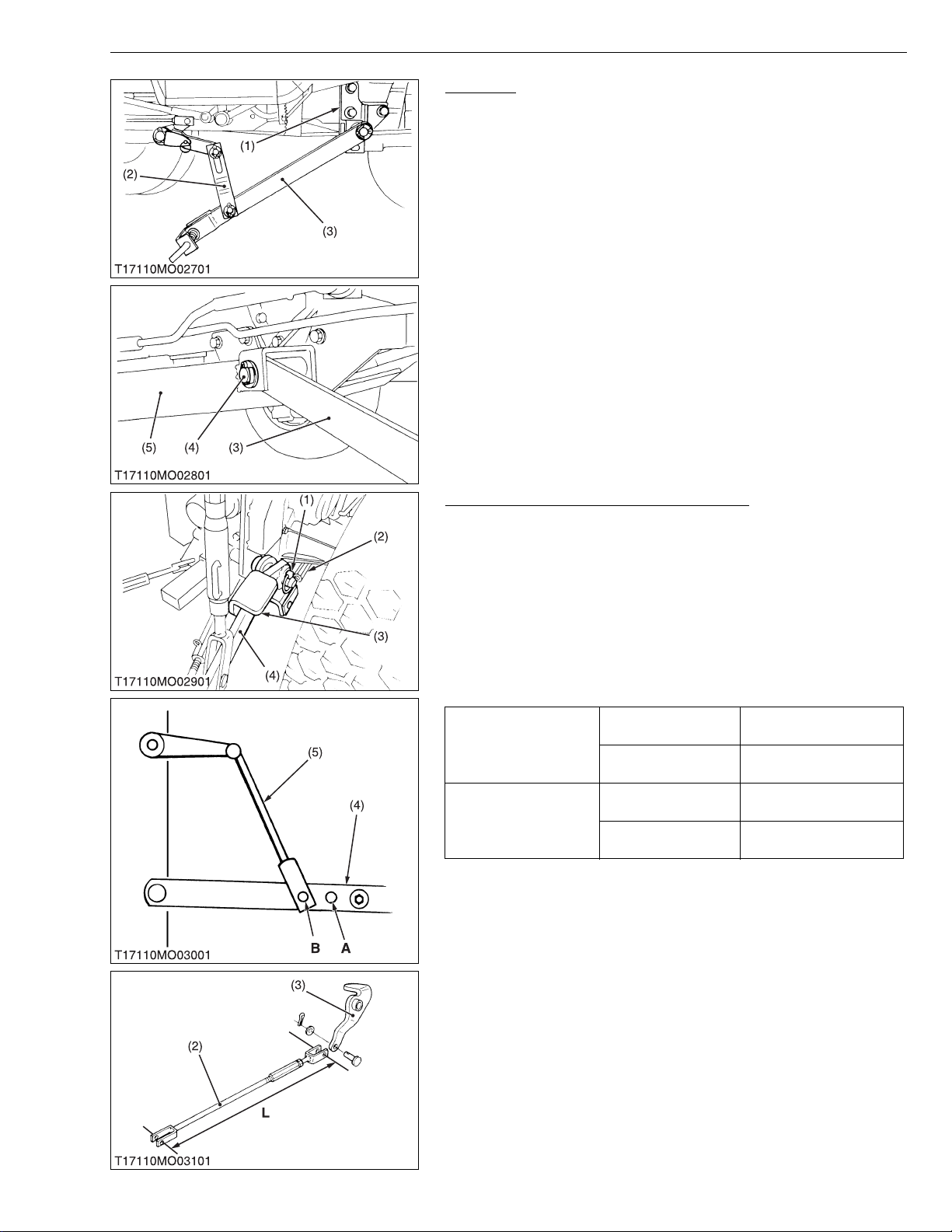
Lift Arm, Lift Link and Connecting Rod
1. Install the lift arms (2), lift links (3) and connecting rods (1) to the
rear hanger bracket with plain washers and cotter pins.
• The lift cylinder type does not use the connecting rod (1).
• Completely bend t he cotter pin (5) to prevent contact with
link stopper as shown in the figure.
• When assembling the connecting rod, insert the clevis pin
(6), (7) care with the direction as shown in figure, and be sure
to properly bend the cotter pin.
(1) Connecting Rod
(2) Lift Arm
(3) Lift Link
(4) Link Stopper
(5) Cotter Pin
(6) Clevis Pin
(7) Clevis Pin
(A) RCK54-24B-EC, RCK60-24B-EC,
RC60-24BR, RC60-27BR with 3Point Hitch Lift Type
(B) RCK60-27B-EC with 3-Point Hitch
Lift Type
(C) RCK54-24B-EC, RCK60-24B-EC,
RCK60-27B-EC
(D) RC60-24BR, RC60-27BR
W1016829
G-16
Page 28
RCK54/60-24B-EC · RCK60-27B-EC · RC60-24/27BR, WSM
IMPORTANT■
KiSC issued 11, 2006 A
G GENERAL
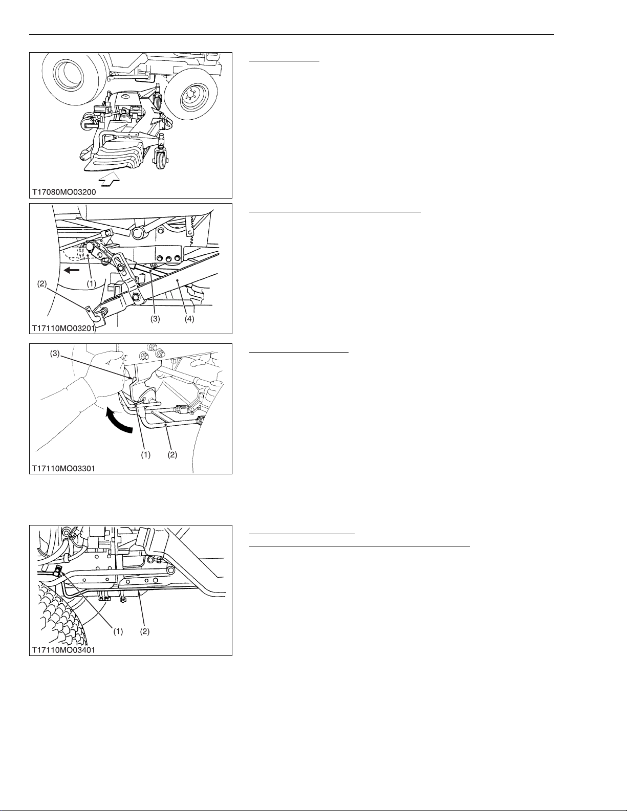
Rear Link
(When mounting the mower only)
1. Install the rear link s (3 ) to t he mid hanger bracket s (1 ) w ith pl ain
washers and cotter pins.
2. Attach the lift links (2) to the rear links (3) with clevis pins, plain
washers and cotter pins.
(When mounting the mower with front loader)
1. Install the rear links (3) to the front loader frame (5) with pins (4),
plain washers and cotter pins.
2. Attach the lift links (2) to the rear links (3) with clevis pins, plain
washers and cotter pins.
(1) Mid Hanger Bracket
(2) Lift Link
(3) Rear Link
(4) Pin (20 mm dia. × 135 mm length,
0.79 in. dia. × 5.31 in. length)
(5) Front Loader Frame
W1017268
Lift Bracket (3-Point Hitch Lift Type Only)
1. Remove the spacer and lower links from the shaft of lower link.
2. Attach both lift brackets (3) inside the lower links (4) with the
lower link pins (1) as shown in the figure.
3. Connect the connecting rods (2) to the lift brackets (3) with clevis
pins, plain washers and cotter pins.
• Connect the lift rods (5) of the tractor as below, and adjust
the length of both lift rods equally with the turnbuckle of the
right lift rod.
(Reference)
Tractor lift rod and lower
link setting position
Connecting rod length
(L)
(1) Lower Link Pin
(2) Connecting Rod
(3) Lift Bracket
(4) Lower Link
(5) Lift Rod
B2410
B2710
B1710
B2110
RCK54-24B-EC
RCK60-24B-EC
RCK60-27B-EC
A : Lift rod and lower link setting
position
B : Lift rod and lower link setting
position
A Position
B Position
620 mm
24.4 in.
665 mm
26.2 in.
W1017587
G-17
Page 29
RCK54/60-24B-EC · RCK60-27B-EC · RC60-24/27BR, WSM
NOTE■
IMPORTANT■
KiSC issued 11, 2006 A
G GENERAL
Setting Mower
1. Turn the steering wheel fully left.
2. Install the mower from right side of the tractor.
3. Roll the mo wer under the tractor, and then retur n the steering
wheel.
W1030314
Mounting Universal Joint Rear Link
1. Pull back the coupler (1) of the universal joint.
2. Push the univ er sal j oi nt (3) onto the mid -P TO shaft, a nd r el ease
the coupler (1).
3. Slide the universal joint back and forward to make sure the
universal joint is locked securely.
4. Lower the rear links.
5. Attach the rear links (4) to the mower deck, pulling the L-pins (2).
(1) Coupler
(2) L-Pin
(3) Universal Joint
(4) Rear Link
W1030772
Mounting Front Link
1. Push down the link fixing lever, pulling the L-pin.
2. Hook the front link (2) to the level fulcrum, and turn the link fixing
lever (1).
3. Return the L-pin (3).
• Make sure the link fixing lever (1) is fixed with L-pin (3)
securely.
• After mounted the mower, be sure to check the mower deck
and tractor body are not interference.
(1) Link Fixing Lever
(2) Front Link
(3) L-pin
W1031053
Hydraulic Pipe Fitting
(RCK54-24B-EC, RCK60-24B-EC, RC60-24BR)
1. Loosen the screw (1) and pull up the hydraulic pipe (2) on
underside of machine, then retighten the screw ( 1) to keep the
gear box of mower and the hydraulic pipe (2) out of contact.
2. Operate the hydraulic control l ever rearward to ri se the highest
position.
3. Make su re th at the g ear box o f m owe r and hydraulic pipe (2) do
not contact.
(1) Screw (2) Hydraulic Pipe
W1018237
G-18
Page 30
RCK54/60-24B-EC · RCK60-27B-EC · RC60-24/27BR, WSM
KiSC issued 11, 2006 A
G GENERAL
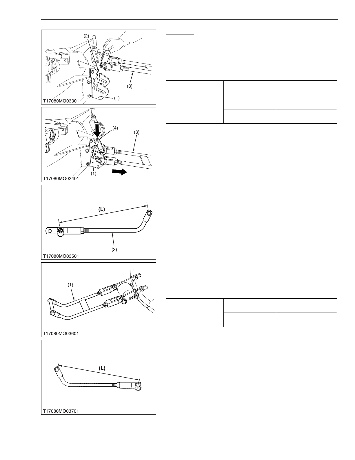
Front Link
[Side Discharge]
1. Hook the front link (3) with the clevis pin section to front e nd of
the groove (2), and then turn the stopper (4) as shown in the
figure.
(Reference)
• Make sure the length (L) of the front link (3) as below.
510.0 mm
20.08 in.
505.0 mm
19.88 in.
500.0 mm
19.69 in.
Front link length (L)
RCK54-24B-EC
RCK60-24B-EC
RCK60-27B-EC
(1) Stay
(2) Groove
(3) Front Link
(4) Stopper
W1030496
[Rear Discharge]
1. Attach the front link (1) to the deck with clevis pins, plain washers
and rings.
(Reference)
• Make sure the length (L) of the front link as below.
RC60-24BR
Front link length (L)
RC60-27BR
470.0 mm
18.5 in.
530.0 mm
20.9 in.
(1) Front Link
W1030661
G-19
Page 31

RCK54/60-24B-EC · RCK60-27B-EC · RC60-24/27BR, WSM
■
KiSC issued 11, 2006 A
G GENERAL
Adjusting Front Link (Lift Cylinder Type)
CAUTION
• Before starting engine, make sure that all levers (in cluding
auxiliary hydraulic control lever) are in neutral position.
• Shut off the engine and allow the mower blades to stop
before making adjustment.
1. Park the tractor on a firm, flat and level surface.
2. Raise the mo wer and set the he ig ht of m ower ga uge whee ls the
same.
3. Lower the mower to the ground.
4. If the gauge wheels are not on the gr ound, remov e the fron t link
from the mower. And adjust the length (L) of the front link (1) until
the gauge wheels come into contact with the ground.
5. Attach the front link to the mower.
6. Start the engine.
7. Operate the a uxil iary hydr auli c con trol lev er rear ward to rise the
mower.
8. Stop the e ngine then check whether the mower is level. If the
mower is not level, lower the mower to the ground and adjust the
clevis (2).
IMPORTANT
• Tire pressure must be correct.
(1) Front Link
(2) Clevis
(A) RCK54-24B-EC, RCK60-24B-EC,
RCK60-27B-EC
(B) RC60-24BR, RC60-27BR
W1018742
G-20
Page 32

RCK54/60-24B-EC · RCK60-27B-EC · RC60-24/27BR, WSM
IMPORTANT■
KiSC issued 11, 2006 A
G GENERAL
Adjusting Front Link and Connecting Rod
(3-Point Hitch Lift Type)
CAUTION
• Before starting the engine, change the mid-PTO and gear
shift lever into neutral.
• Shut off the engine and allow the mower blades to stop
before making adjustments.
1. Park the tractor on a firm, flat and level surface.
2. Raise the mower and se t the hei ght o f the m ower ga uge wheels
the same.
3. Lower the mower to the ground.
4. If the gauge wheels are not on the gr ound, remo ve the fro nt link
from the mower. And adjust the length (L) of the front link (1) until
the gauge wheels come into contract with the ground.
5. Attach the front link to the mower.
6. Start the engine.
7. Lift the mower to the maximu m lifting position and shut off the
engine.
8. Adjust the turnbuckles (7) of the left and right connecting rods (6)
so that the clearances are within the factory specifications.
Clearance (C)
between front
stopper and mid
hanger bracket
Clearance (D)
between rear
stopper and
tractor frame
Factory
spec.
Factory
spec.
RCK54-24B-EC
RCK60-24B-EC
RCK60-27B-EC
RC60-24BR
RC60-27BR
RCK54-24B-EC
RCK60-24B-EC
RCK60-27B-EC
RC60-24BR
RC60-27BR
2.0 to 4.0 mm
0.08 to 0.15 in.
2.0 to 5.0 mm
0.08 to 0.20 in.
0 mm, 0 in.
LH
Just contact
5.0 to 8.0 mm
RH
0.20 to 0.31 in.
LH
5.0 to 10.0 mm
and
0.20 to 0.39 in.
RH
• Proper adjustment for the connecting rod length is very
important to avoid damage to the mower lifting system.
• Tire pressure must be correct.
(1) Front Link
(2) Mid Hanger Bracket
(3) Front Stopper
(4) Tractor Frame
(5) Rear Stopper
(6) Connecting Rod
(7) Turnbuckle
(A) RCk54-24B-EC, RCK60-24B-EC,
RCK60-27B-EC
(B) RC60-24BR, RC60-27BR
W1019204
G-21
Page 33

MECHANISM
KiSC issued 11, 2006 A
CONTENTS
1. POWER TRANSMISSION ...................... ...... ....... ...... ....... ...... ....... ...... ....... .... M-1
2. LIFTING MECHANISM ...................................................................................M-3
[1] MOWER LIFT CYLINDER TYPE............................................................M-3
[2] 3-POINTS HITCH LIFT TYPE.................................................................M-4
Page 34

RCK54/60-24B-EC · RCK60-27B-EC · RC60-24/27BR, WSM
KiSC issued 11, 2006 A
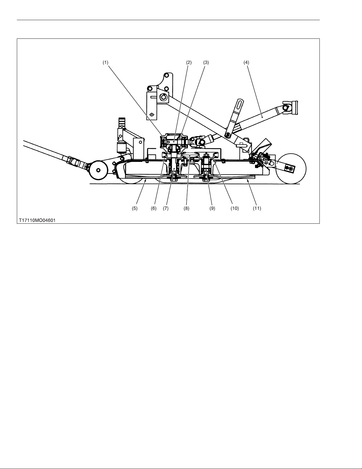
1. POWER TRANSMISSION
[RCK54-24B-EC, RCK60-24B-EC, RCK60-27B-EC]
ROTARY MOWER
(1) 19T Bevel Gear (RCK60-24B-
EC, RCK60-27B-EC)
21T Bevel Gear
(RCK54-24B-EC)
(2) 16T Bevel Gear
(3) Pinion Shaft
(4) Universal Joint
(5) Mid-PTO Shaft
(6) Center Blade
(7) Center Pulley
(8) Bevel Gear Shaft
(9) Mower Belt
(10) Blade Shaft
(11) Outer Pulley
(12) Outer Blade
The power is transmitted from mid-PTO to blades as follows:
■ Center Blade
Mid-PTO Shaft (5) → Universal Joint (4 ) → Pinion Shaft (3) → Bevel Gear (1) → Bevel Gear (2) → Bevel Ge ar
Shaft (8) → Center Blade (6)
■ Outer Blade
Mid-PTO Shaft (5) → Universal Joint (4 ) → Pinion Shaft (3) → Bevel Gear (1) → Bevel Gear (2) → Bevel Ge ar
Shaft (8) → Center Pulley (7) → Mower Belt (9) → Outer Pulley (11) → Blade Shaft (10) → Outer Blade (12)
M-1
Page 35
RCK54/60-24B-EC · RCK60-27B-EC · RC60-24/27BR, WSM
KiSC issued 11, 2006 A
[RC60-24BR, RC60-27BR]
ROTARY MOWER
(1) 16T Bevel Gear
(2) Pinion Shaft
(3) 19T Bevel Gear
(4) Universal Joint
(5) Center Blade
(6) Center Pulley
(7) Bevel Gear Shaft
(8) Mower Belt
(9) Blade Shaft
(10) Outer Pulley
(11) Outer Blade
The power is transmitted from mid-PTO to blades as follows :
■ Center Blade
Mid-PTO Shaft → Universal Joint (4) → Pinion Shaft (2) → 19T Bevel Gear (3) → 16T Bevel Gear (1) → Bevel
Gear Shaft (7) → Center Blade (5)
■ Outer Blad e
Mid-PTO Shaft → Universal Joint (4) → Pinion Shaft (2) → 19T Bevel Gear (3) → 16T Bevel Gear (1) → Bevel
Gear Shaft (7) → Center Pulley (6) → Mower Belt (8) → Outer Pulley (10) → Blade Shaft (9) → Outer Blade (11)
M-2
Page 36
RCK54/60-24B-EC · RCK60-27B-EC · RC60-24/27BR, WSM
KiSC issued 11, 2006 A
2. LIFTING MECHANISM
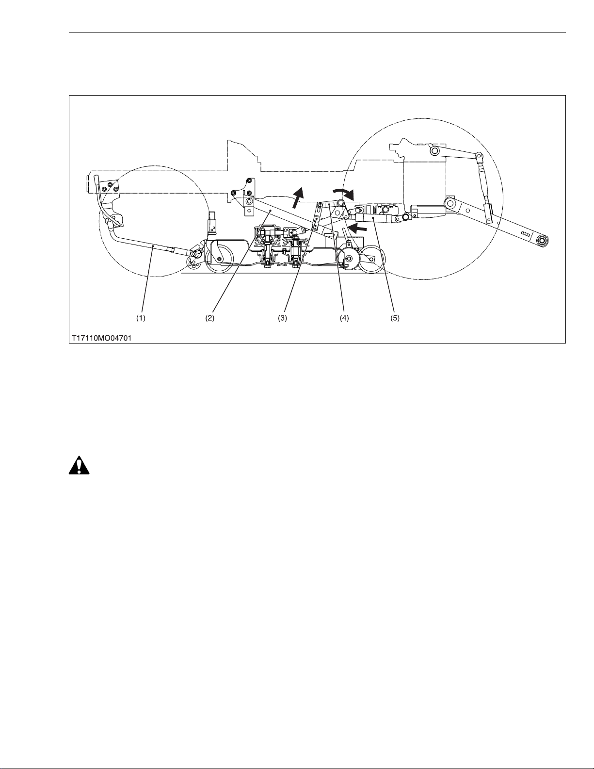
[1] MOWER LIFT CYLINDER TYPE
ROTARY MOWER
(1) Front Link
(2) Rear Link
The lifting of mower is performed by the hydraulic system installed on the tractor.
For avoiding danger , the mower should be kep t lifting when traveling. W hen the auxiliary contr ol valve lever is
moved to “LIFT” position, th e mower lift cyl inders (5) retract by the oil press ure, and the cy linder rods are pushed
forward.
Therefore, lift arms (4) round and the mower is lifted by the lift links (3) and rear links.
As this link system is a parallel linkage, the mower can be kept parallel at every position.
CAUTION
• Never operate mower in transport position.
(3) Lift Link (4) Lift Arm (5) Mower Lift Cylinder
M-3
Page 37

RCK54/60-24B-EC · RCK60-27B-EC · RC60-24/27BR, WSM
KiSC issued 11, 2006 A
[2] 3-POINTS HITCH LIFT TYPE
ROTARY MOWER
(1) Front Link
(2) Rear Link
(3) Lift Link
(4) Lift Arm
(5) Connecting Rod (6) Lower Link
The lifting of mower is performed by the hydraulic system installed on the tractor.
For avoiding danger, the mower should be kept lifting when traveling. When the position control lever is moved to
“LIFT” position, the lower link s (6) ar e ris en b y th e oi l pres s ur e of h yd rauli c sy st em, a nd th e co nne cti ng ro ds ( 5) ar e
pulled rearward.
Therefore, lift arms (4) round and the mower is lifted by the lift links (3) and rear links.
As this link system is a parallel linkage, the mower can be kept parallel at every position.
CAUTION
• Never operate mower in transport position.
M-4
Page 38

SERVICING
KiSC issued 11, 2006 A
CONTENTS
1. TROUBLESHOOTING......................................................................................S-1
2. SERVICING SPECIFICATIONS ......................................................................S-2
3. TIGHTENING TORQUES ............................. ....... ...... ....... ...... ....... ...... ....... .....S-3
4. CHECKING, DISASSEMBLING AND SERVICING........................................S-4
[1] CHECKING AND ADJUSTING.................................................................S-4
[2] DISASSEMBLING AND ASSEMBLING....................................................S-7
(1) RCK54-24B-EC, RCK60-24B-EC, RCK60-27B-EC
(Side Discharge Mower) .......................................................................S-7
(2) RC60-24BR, RC60-27BR (Rear Discharge Mower)...........................S-11
[3] SERVICING ..............................................................................................S-16
Page 39

RCK54/60-24B-EC · RCK60-27B-EC · RC60-24/27BR, WSM
KiSC issued 11, 2006 A
1. TROUBLESHOOTING
ROTARY MOWER
Symptom Probable Cause Solution
Blade Does Not Turn • Mid-PTO system malfunctioning
• Broken mower belt
Blade Speed Is Slow • Loosen mower belt
• Clogged grass
• Flattened out or worn cup washer
Cutting Is Poor • Worn or broken mower blade
• Loosen mower blade screw
• Cutting height improper
Mower Is Not Lifted • Broken linkage system
• Trouble of hydraulic system
Check transmission
Replace mower belt
Replace mower belt
or tension spring
Remove grass
Replace cup washer
Sharpen or replace
mower blade
Retighten mower
blade screw
Adjust cutting height
Replace linkage
system
Check hydraulic
system
Reference
Page
–
S-4
S-4
–
S-7, 11
S-4
S-7, 11
S-5, 6
–
–
W1014322
S-1
Page 40

RCK54/60-24B-EC · RCK60-27B-EC · RC60-24/27BR, WSM
KiSC issued 11, 2006 A
2. SERVICING SPECIFICATIONS
Item Factory Specification Allowable Limit
Pinion Shaft (without Mower Belt) Turning Force Less than 117.7 N
12.0 kgf
26.5 lbs
Turning Torque Less than 1.47 N·m
0.15 kgf·m
1.08 ft-lbs
Bevel Gears in Gear Box Backlash
RCK54-24B-EC
RCK60-24B-EC
Backlash
RCK60-27B-EC
RC60-24BR
RC60-27BR
0.10 to 0.20 mm
0.0039 to 0.0079 in.
0.13 to 0.25 mm
0.0051 to 0.0098 in.
ROTARY MOWER
–
–
0.40 mm
0.0157 in.
0.40 mm
0.0157 in.
W1013874
S-2
Page 41

RCK54/60-24B-EC · RCK60-27B-EC · RC60-24/27BR, WSM
KiSC issued 11, 2006 A
3. TIGHTENING TORQUES
Tightening torques of screws, bolts and nuts on the table below are especially specified.
(For general use screws, bolts and nuts: See page G-4.)
Item N·m kgf·m ft-lbs
Mower blade screw
Gear box mounting screw
Standard type / Reamer type
Center pulley holder screw
Standard type / Reamer type
Outer pulley mounting nut
Pulley holder mounting screw
98.1 to 117.7
77.6 to 90.2
77.6 to 90.2
166.7 to 186.3
77.4 to 90.2
10.0 to 12.0
8.0 to 9.2
8.0 to 9.2
17.0 to 19.0
7.9 to 9.2
ROTARY MOWER
72.3 to 86.8
57.1 to 66.5
57.1 to 66.5
123.0 to 137.4
57.1 to 66.5
W1012736
S-3
Page 42
RCK54/60-24B-EC · RCK60-27B-EC · RC60-24/27BR, WSM
IMPORTANT■
NOTE■
KiSC issued 11, 2006 A
ROTARY MOWER
4. CHECKING, DISASSEMBLING AND SERVICING
[1] CHECKING AND ADJUSTING
Checking Mower Blade
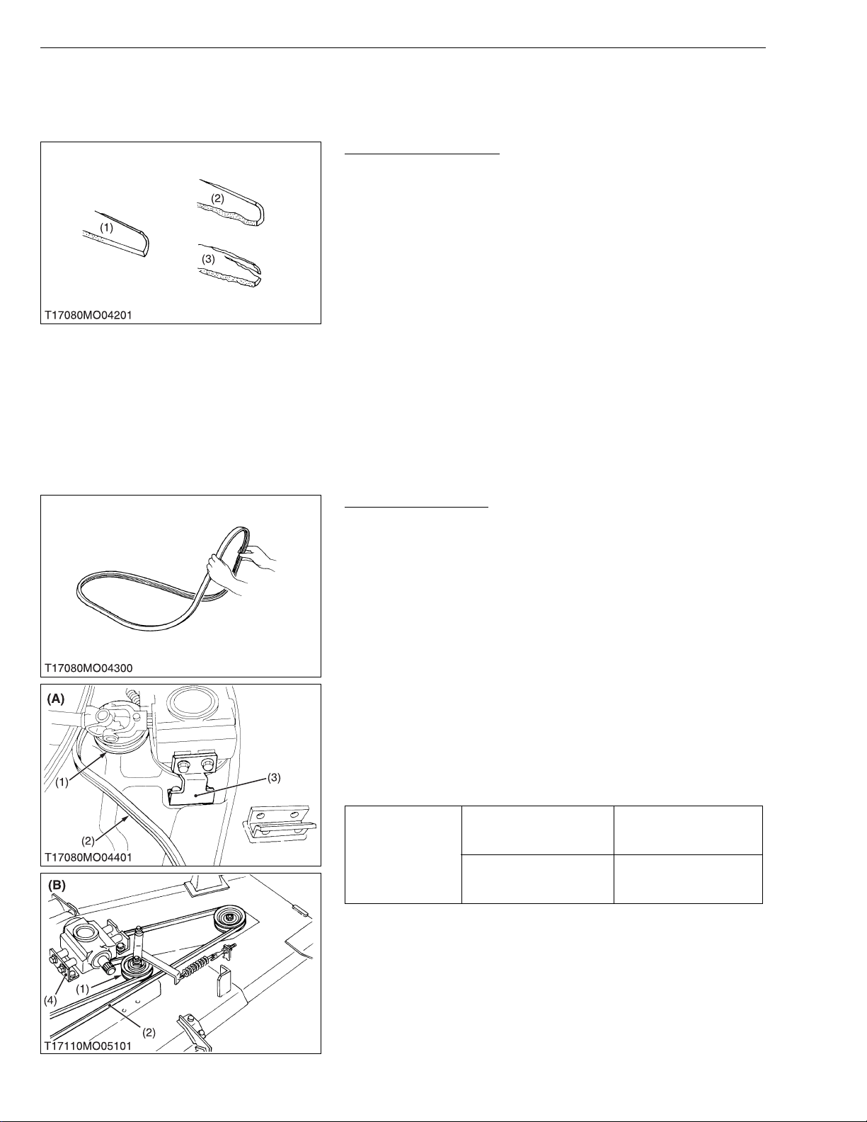
1. Check the cutting edge of mower blade.
2. Sharpen the cu tting edge s, if the mowe r blades ar e as shown in
figure (2).
3. Replace the mower blades, if they are as shown in figure (3).
• Never forget to set the dust cover (RCK54-24B-EC, RCK6024B-EC, RCK60-27B-EC), friction plate (center blade of
RC60-24BR), two cup washers and spline boss, when
reassembling the mower blades. (See page S-7, 11.)
• To sharpen the mower blades by yourself, clamp the mower
blade securely in a vise a nd use a large mill file along the
original bevel.
• To balance the mower blade, place a small rod through the
center hole and check to see if the blade balance evenly.
File heavy side of the blade until it balance out even.
(1) New Blade
(2) Worn Blade
Checking Mower Belt
1. Check to see the mower belt.
2. Replace the mower belt with a new one, if there is found surface
split at more than 3 positions.
(When replacing mower belt)
1. Dismount the mower from the tractor.
2. Remove the left and right hand belt cover from the mower deck.
3. Clean around the gear box .
4. Remove the right hand stay (3) which mounts the gear box to the
mower deck. (RCK54-24B-EC, RCK60-24B-EC, RCK60-27BEC)
Remove the left hand stay (4) which moun ts the gear box to the
mower deck. (RC60-24BR, RC60-27BR)
5. Remove the mower belt (2) from the tens ion pulley (1) . Slip the
mower belt over the top of the gear box.
6. To install a new belt, reverse the above procedure.
7. Be sure to ad just t he tens ion spr ing le ngth (RC60- 24BR, RC6027BR). Refer with page S-13.
Gear box mounting screw
(Standard type / Reamer
Tightening torque
type)
Center pulley holder screw
(Standard type / Reamer
type)
(3) Cracked Blade
77.6 to 90.2 N·m
8.0 to 9.2 kgf·m
57.1 to 66.5 ft-lbs
77.6 to 90.2 N·m
8.0 to 9.2 kgf·m
57.1 to 66.5 ft-lbs
W1011041
(1) Tension Pulley
(2) Mower Belt
(3) Gear Box Stay (Right)
(4) Gear Box Stay (Left)
S-4
(A) RCK54-24B-EC, RCK60-24B-EC,
RCK60-27B-EC
(B) RC60-24BR, RCK60-27BR
W1011180
Page 43
RCK54/60-24B-EC · RCK60-27B-EC · RC60-24/27BR, WSM
IMPORTANT■
KiSC issued 11, 2006 A
ROTARY MOWER
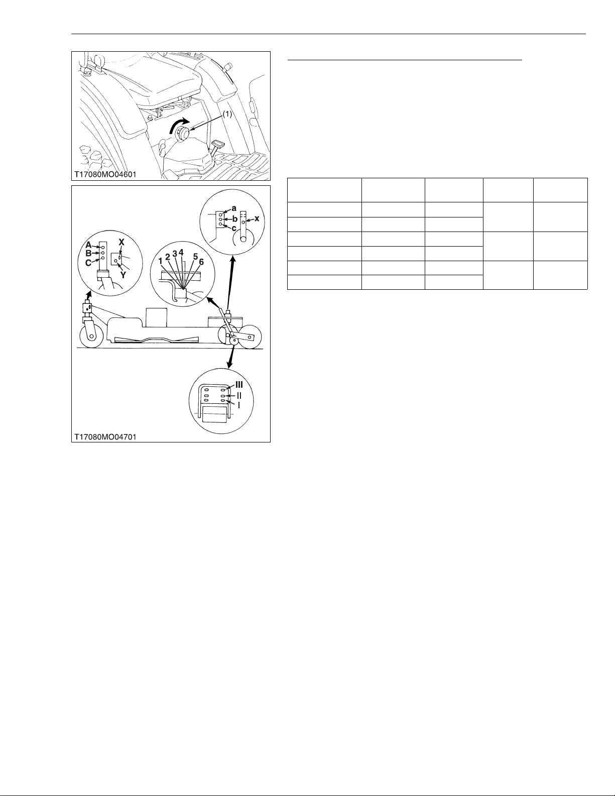
Adjusting Cutting Height (Side Discharge Mower)
1. The cutting height can be adjusted from 38 mm to 102 mm (from
1.5 in. to 4.0 in.).
2. To adjust the cut tin g heigh t, lift the mowe r slig htly a nd cl ose the
3-point lowering speed knob (1).
3. Adjust the cutting height with the front gauge wheels, rear gauge
wheel, anti-scalp whee l and anti-scalp rollers as shown in the
table below.
The recommend cutting height is approx. 50 mm (2.0 in.).
[RCK54-24B-EC, RCK60-24B-EC, RCK60-27B-EC]
Cutting height
35 mm (1.5 in.) C-X 1
51 mm (2.0 in.) C-Y 2
64 mm (2.5 in.) B-X 3
76 mm (3.0 in.) B-Y 4
89 mm (3.5 in.) A-X 5
102 mm (4.0 in.) A-Y 6
Front gauge
wheel
Rear gauge
wheel
Anti-scalp
wheel
a-x I
b-x II
c-x III
Anti-scalp
roller
• After adjusting the cutting height, open the 3-point lowe ring
speed knob (1) and adjust the lowering speed of the mower.
(1) 3-point Lowering Speed Knob
W1011439
S-5
Page 44

RCK54/60-24B-EC · RCK60-27B-EC · RC60-24/27BR, WSM
IMPORTANT■
KiSC issued 11, 2006 A
ROTARY MOWER
Adjusting Cutting Height (Rear Discharge Mower)
1. The cuttin g height can be adjuste d from 25 mm to 89 mm (from
1.0 in. to 3.5 in.).
2. To adjust th e cutting height , lift th e mower s ligh tly and c lose the
3-point lowering speed knob.
3. To adjust the cutting height, set the front gauge wheels, antiscalp skids and rear gauge wheels as shown in the table below.
The recommended cutting height is approx. 50 mm (2.0 in.).
[RC60-24BR, RC60-27BR]
Cutting height Front gauge wheel
25 mm (1.0 in.) C-X 1
38 mm (1.5 in.) C-Y 2
50 mm (2.0 in.) B-X 3
64 mm (2.5 in.) B-Y 4
76 mm (3.0 in.) A-X 5
89 mm (3.5 in.) A-Y 6
Rear gauge
wheel
Anti-scalp
skid
I
II
• After adjusting the cutting height, open the 3-point lowering
speed knob and adjust the lowering speed of the mower.
W1012112
Adjusting Front Link and Connecting Rod
1. See page G-20, 21.
W1012485
S-6
Page 45
RCK54/60-24B-EC · RCK60-27B-EC · RC60-24/27BR, WSM
NOTE■
IMPORTANT■
KiSC issued 11, 2006 A
ROTARY MOWER
[2] DISASSEMBLING AND ASSEMBLING
(1) RCK54-24B-EC, RCK60-24B-EC, RCK60-27B-EC (Side Discharge Mower)
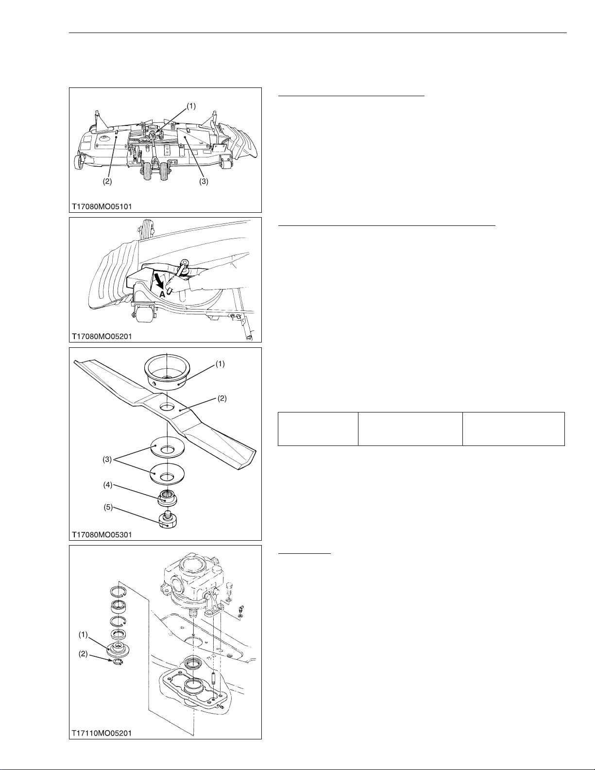
Universal Joint and Belt Covers
1. Remove the universal joint (1).
2. Remove the left and right belt covers (2), (3).
(1) Universal Joint
(2) Belt Cover (Left)
Mower Blades (Center Blade and Outer Blades)
1. Turn over the mower.
2. Unscrew the mower blade screw (5), and remove the spline boss
(4), two cup washers (3), mower blade (2) and dust cover (1).
• To remove the blade securely, wedge a block of wood
between one blade and the mower deck in such position that
it will hold the blade safely while loosing or tightening the
blade screw.
(When reassembling)
• Be sure to assemb le the two cup washers betwee n the mower
blade and spline boss.
(3) Belt Cover (Right)
W1012580
• Make sure the cup washer is not flattened out or worn,
causing blade to slip easily.
Replace two cup washers if either is damaged.
98.1 to 117.7 N·m
Tightening torque Mower blade screw
(1) Dust Cover
(2) Mower Blade
(3) Cup Washer
(4) Spline Boss
(5) Mower Blade Screw
A : Loosen
10.0 to 12.0 kgf·m
72.3 to 86.8 ft-lbs
W1012667
Blade Boss
1. Remove the external snap ring (2).
2. Remove the blade boss (1).
(1) Blade Boss (2) External Snap Ring
W1012871
S-7
Page 46
RCK54/60-24B-EC · RCK60-27B-EC · RC60-24/27BR, WSM
KiSC issued 11, 2006 A
ROTARY MOWER
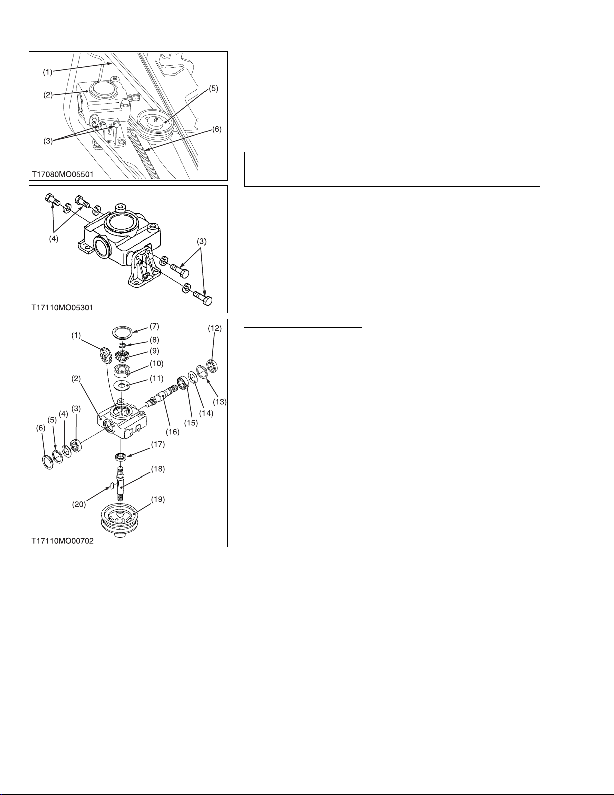
Gear Box and Mower Belt
1. Turn over the mower.
2. Remove the mower belt (1) from the tension pulley (5).
3. Unscrew the left and right gear box mounting screws (3), (4) and
remove the gear box (2) from the mower deck.
(When reassembling)
• Install the reamer screws (3) at their origi nal posi tions as sh own
in the figure.
77.6 to 90.2 N·m
Tightening torque Gear box mounting screw
8.0 to 9.2 kgf·m
57.1 to 66.5 ft-lbs
(1) Mower Belt
(2) Gear Box
(3) Gear Box Mounting Screw
(Reamer Screw)
(4) Gear Box Mounting Screw
(5) Tension Pulley
(6) Tension Spring
W1012961
Disassembling Gear Box
1. Unscrew the drain plug, and drain gear box oil.
2. Remove the center pulley (19) with a puller, and remove the
feather key (20) on the bevel gear shaft (18).
3. Remove the gear box caps (6), (7).
4. Remove the oil seal (12), internal snap ring (13) and shim (14).
5. Tap out the pinion shaft (16) with the ball bearing (15), and
remove the bevel gear (1).
6. Remove the internal snap ring (5), shim (4) and ball bearing (3).
7. Remove the external snap ring ( 8), and dr aw out the bev el gear
shaft (18).
8. Remove the b evel gear (9), ball b earing (10), shim (11) an d oil
seal (17).
(When reassembling)
• Replace the o il seals (12), (17) a nd gear box caps (6), (7) with
new ones.
• Check the backlash and turning torque.
If not proper, adjust with the shims (5), (11), (14).
(See page S-16, 17)
(1) 19T Bevel Gear (RCK60-24B-EC,
RCK60-27B-EC)
21T Bevel Gear (RCK54-24B-EC)
(2) Gear Box
(3) Ball Bearing
(4) Shim
(5) Internal Snap Ring
(6) Gear Box Cap
(7) Gear Box Cap
(8) External Snap Ring
(9) 16T Bevel Gear
(10) Ball Bearing
(11) Shim
(12) Oil Seal
(13) Internal Snap Ring
(14) Shim
(15) Ball Bearing
(16) Pinion Shaft
(17) Oil Seal
(18) Bevel Gear Shaft
(19) Center Pulley
(20) Feather Key
W1013296
S-8
Page 47
RCK54/60-24B-EC · RCK60-27B-EC · RC60-24/27BR, WSM
NOTE■
KiSC issued 11, 2006 A
ROTARY MOWER
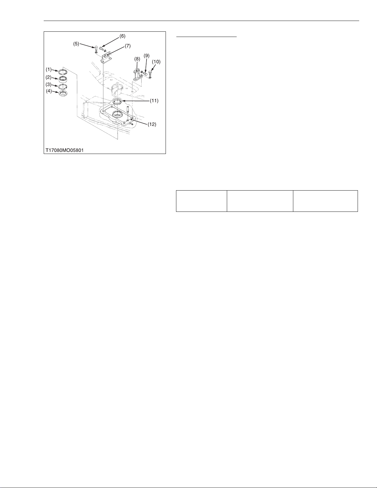
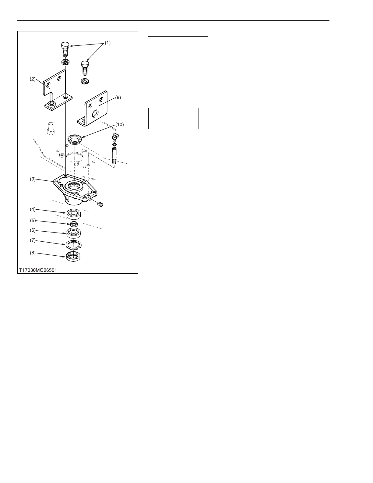
Center Pulley Holder
1. Unscrew the center p ull ey ho lde r scr ews (5 ) and re ame r sc rews
(10).
2. Remove the upper oil seal (11) and lower oil seal (4).
3. Remove the internal snap ring (3) and ball bearing (2).
(When reassembling)
• Replace the oil seals (4), (11) with new ones.
• Install the reamer screws (10) at their original positions as shown
in the figure.
• When reassembling the center pulley holder (12), gear box
and gear box stays (7), (8), screw the all screws by hand
temporary.
• Tighten the screws in the order as below, to prevent the
incline the gear box.
• Tighten the reamer screws (9) to the gear box first, then
tighten the reamer s crews (10) to the center pulley ho lder
(12) with specified torque.
• Tighten the gear box screws (6) to the gear box, then tighten
the center pulley holder screws (5) with specified torque.
• See page S-8 for tightening torque of gear box screw.
Tightening torque
Center pulley holder screw
(Standard type / Reamer
type)
77.6 to 90.2 N·m
8.0 to 9.2 kgf·m
57.1 to 65.1 ft-lbs
(1) Internal Snap Ring
(2) Ball Bearing
(3) Internal Snap Ring
(4) Oil Seal
(5) Center Pulley Holder Screw
(6) Gear Box Screw
(7) Gear Box Stay RH
(8) Gear Box Stay LH
(9) Gear Box Ream er Screw
(10) Center Pulley Holder Reamer
Screw
(11) O il Seal
(12) Center Pulley Holder
W1013720
S-9
Page 48
RCK54/60-24B-EC · RCK60-27B-EC · RC60-24/27BR, WSM
KiSC issued 11, 2006 A
ROTARY MOWER
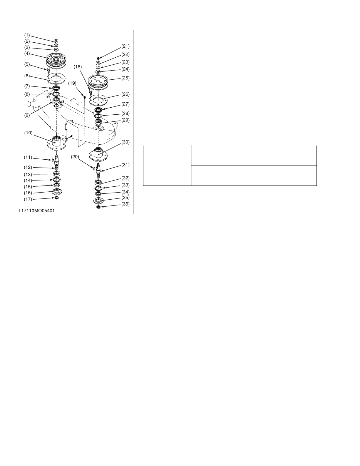
Outer Pulley and Blade Shaft
1. Unscrew the outer pulley mounting nut (22), and remove the
outer pulley (25) and feather key (20).
2. Unscrew the pulley holder mou nting screws (18), and separate
the left pulley holder (30) and plate (26) from the mower deck.
3. Remove the external snap ring (36) on the left blade shaft (31).
4. Remove the spline boss (35) and oil seal (34).
5. Remove the internal snap ring (33) and tap out the left blade shaft
(31) with the ball bear ings (29), (3 2), taking c are not to dama ge
the grease nipple (21).
6. Remove the oil seal (27) and internal snap ring (28).
7. Remove the ball bearings (29), (32) from the blade shaft (31).
8. Remove the right pulley holder (10) and blade shaft (12) as
above.
(When reassembling)
• Replace the oil seals (34), (27), (15) and (7) with new ones.
166.7 to 186.3 N·m
Outer pulley mounting nut
Tightening torque
Pulley holder mounting
screw
17.0 to 19.0 kgf·m
123.0 to 137.4 ft-lbs
77.4 to 90.2 N·m
7.9 to 9.2 kgf·m
57.1 to 66.5 ft-lbs
(1) O ut er Pulley Mounting Nut
(2) Spring Washer
(3) P lain Washer
(4) O ut er Pulley (Right)
(5) Pulley Holder Mounting Screw
(6) Plate
(7) Oil Seal
(8) Internal Snap Ring
(9) Ball Bearing
(10) Pulley Holder (Left)
(11) Feather Key
(12) Blade Shaft (Right)
(13) Ball Bearing
(14) Internal Snap Ring
(15) Oil Seal
(16) Spline Boss
(17) External Snap Ring
(18) Pulley Holder Mounting Screw
(19) Grease Nipple
(20) Feather Key
(21) Grease Nipple
(22) Outer Pulley Mounting Nut
(23) Spring Washer
(24) Plain Washer
(25) Outer Pulley (Left)
(26) Plate
(27) Oil Seal
(28) Internal Snap Ring
(29) Ball Bearing
(30) Pulley Holder (Left)
(31) Blade Shaft (Left)
(32) Ball Bearing
(33) Internal Snap Ring
(34) Oil Seal
(35) Spline Boss
(36) External Snap Ring
W1013387
S-10
Page 49
RCK54/60-24B-EC · RCK60-27B-EC · RC60-24/27BR, WSM
■
IMPORTANT■
KiSC issued 11, 2006 A
(2) RC60-24BR, RC60-27BR (Rear Discharge Mower)
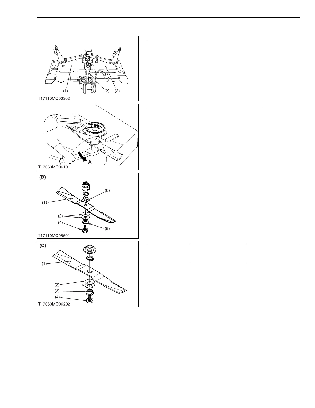
Universal Joint and Belt Covers
1. Remove the universal joint (2) from the pinion shaft.
2. Remove the left and right belt covers (1), (3).
(1) Belt Cover (Left)
(2) Universal Joint
Mower Blades (Center Blade and Outer Blades)
1. Unscrew the mower blade screw (4), and remove the spline boss
(3) for RC60-27BR, lock washer (5) for RC60-24BR, two cup
washers (2) and mower blade (1).
NOTE
• The mower blade screw has left-hand threads.
Turn it counterclockwise to loosen (A).
• Wedge a block of wood between the mower blade and
mower deck or use a box wrench over the pulley nut to
prevent the blade shaft from rotating while removing the
mower blade screw.
• The friction plate (6) ad apts to center blade of RC60-24BR
only.
(When reassembling)
• Be sure to assemble two cup washers between the mower blade
and spline boss.
• Be sure to assem ble the friction plate (6) that ada pt to center
blade of RC60-24BR only.
ROTARY MOWER
(3) Belt Cover (Right)
W1015130
• Make sure the cup washer is not flattened out or worn,
causing blade to slip easily.
Replace the cup washer if either is damaged.
Tightening torque Mower blade screw
(1) Mower Blade
(2) Cup Washer
(3) Spline Boss
(4) Mower Blade Screw
(5) Lock Washer
(6) Friction Plate
(B) RC60-24BR
(C) RC60-27BR
98.1 to 117.7 N·m
10.0 to 12.0 kgf·m
72.3 to 86.8 ft-lbs
W1015217
S-11
Page 50
RCK54/60-24B-EC · RCK60-27B-EC · RC60-24/27BR, WSM
KiSC issued 11, 2006 A
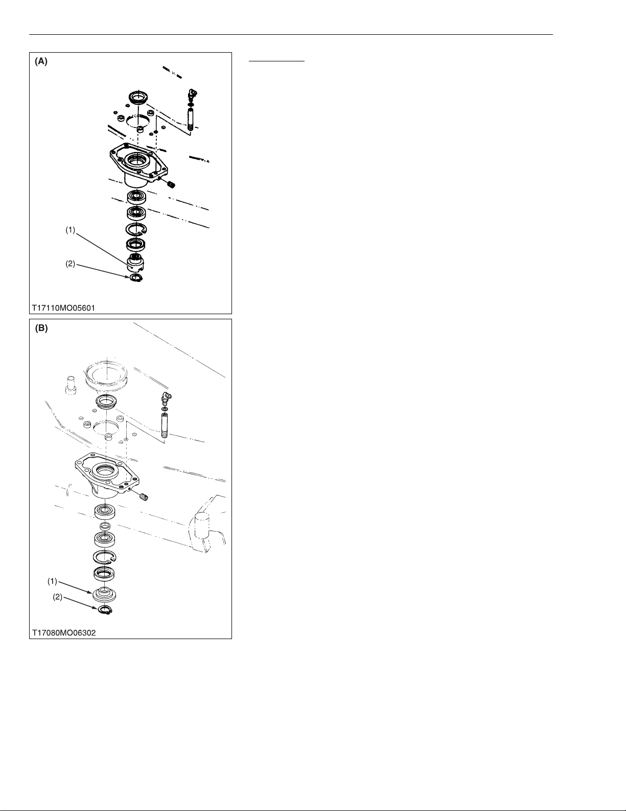
Blade Boss
1. Remove the external snap ring (2).
2. Remove the blade boss (1 ).
(1) Blade Boss
(2) External Snap Ring
(A) RC60-24BR
(B) RC60-27BR
ROTARY MOWER
W1015526
S-12
Page 51
RCK54/60-24B-EC · RCK60-27B-EC · RC60-24/27BR, WSM
KiSC issued 11, 2006 A
ROTARY MOWER
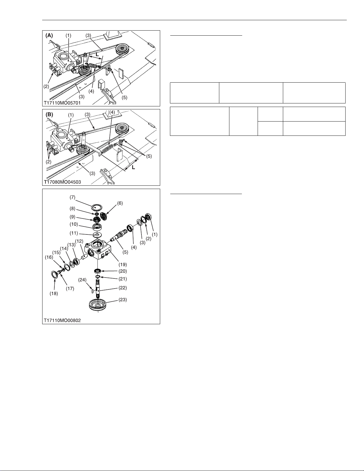
Gear Box and Mower Belt
1. Loosen the belt tension adjusting nuts (5), and remove the
tension spring (4).
2. Unscrew the gear box mounting screws (2), and remove the
mower belt (3).
3. Pull out the gear box (1) upward.
(When reassembling)
77.6 to 90.2 N·m
Tightening torque Gear box mounting screw
8.0 to 9.2 kgf·m
57.1 to 66.5 ft-lbs
Tension spring length
(L)
(1) Gear Box
(2) Gear Box Mounting Screw
(3) Mower Belt
(4) Tension Spring
(5) Belt Tension Adjusting Nut
Factory
spec.
RC6024BR
RC6027BR
(A) RC60-24BR
(B) RC60-27BR
160.0 mm
6.3 in.
245.0 mm
9.7 in.
W1015617
Disassembling Gear Box
1. Unscrew the drain plug, and drain the gear box oil.
2. Remove the center pulley (23) with a puller, and remove the
feather key (24) on the bevel gear shaft.
3. Remove the gear box caps (7), (18).
4. Remove the oil seal (1), external snap ring (2) and shim (3).
5. Remove the screw (17), washer (16) and tap out the pinion shaft
(5) with ball bearing (4).
6. Remove the 19T bevel gear (6) and pinion shaft collar (12).
7. Remove the internal snap ring (15) and shims (14).
8. Remove the ball bearing (13).
9. Remove the externa l snap rin g (8), a nd dra w out the bevel ge ar
shaft (22).
10.Remove the 16T bevel gear (9) with ball bearing (10).
(When reassembling)
• Replace the oil seals (1), (20) and g ear box caps (7), (18 ) with
new ones.
• Check the backlash and turning torque.
If not proper, adjust with the shims (3), (11) and (14). (See page
S-16, 17)
(1) Oil Seal
(2) Internal Snap Ring
(3) Shim
(4) Ball Bearing
(5) Pinion Shaft
(6) 19T Bevel Gear
(7) Gear Box Cap
(8) External Snap Ring
(9) 16T Bevel Gear
(10) Ball Bearing
(11) Shim
(12) Pinion Shaft Collar
(13) Ball Bearing
(14) Shim
(15) Internal Snap Ring
(16) Washer
(17) Sc rew
(18) Gear Box Cap
(19) Gear Box
(20) Oil Seal
(20) Externa l Snap Ring
(21) Bevel Gear Shaft
(23) Center Pulley
(24) Feather Key
W1018511
S-13
Page 52
RCK54/60-24B-EC · RCK60-27B-EC · RC60-24/27BR, WSM
NOTE■
KiSC issued 11, 2006 A
ROTARY MOWER
Center Pulley Holder
1. Unscrew the center pulley holder screws (1), and remove the
center pulley holder from the mower deck.
2. Remove the upper oil seal (10) and lower oil seal (8).
3. Remove the internal snap ring (7), ball bearings (4), (6) and collar
(5).
• The collar (5) adapts to RC60-27BR only.
(When reassembling)
• Replace the oil seals (8), (10) with new ones.
77.6 to 90.2 N·m
Tightening torque Center pulley holder screw
8.0 to 9.2 kgf·m
57.1 to 66.5 ft-lbs
(1) Center Pulley Holder Screw
(2) Gear Box Stay RH
(3) Center Pulley Holder
(4) Ball Bearing
(5) Collar
(6) Ball Bearing
(7) Internal Snap Ring
(8) Oil Seal
(9) Gear Box Stay LH
(10) Oil Seal
W1019050
S-14
Page 53

RCK54/60-24B-EC · RCK60-27B-EC · RC60-24/27BR, WSM
NOTE■
KiSC issued 11, 2006 A
ROTARY MOWER
(A)
Outer Pulley and Blade Shaft
1. Unscrew the outer pulley mounting nut (18), and remove the
outer pulley (21) and feather key (26).
2. Unscrew the pull ey holder mount ing screws (22), a nd separate
the left pulley holder (24) from the mower deck.
3. Remove the external snap ring (32) on the left blade shaft (27).
4. Remove the blade boss (31) and oil seal (30).
5. Remove the internal snap ring (29) and tap out the left blade shaft
(27) with ball bearings ( 25), (28), tak ing care not to damag e the
grease nipple (17).
6. Remove the oil seal (23).
7. Remove the ball bearings (25), (28) from the blade shaft (27).
8. Remove the right pulley holder (8) and blade shaft (11) as above.
• The collar (33) adapts to RC60-24BR only.
(When reassembling)
• Replace the oil seals (30), (23), (14), (6) with new ones.
166.7 to 186.3 N·m
Outer pulley mounting nut
Tightening torque
Pulley holder mounting
screw
(1) Grease Nipple
(2) Outer Pulley Moun ting Nut
(3) Spring Washer
(4) Plain Washer
(5) Outer Pulley (Right)
(6) Oil Seal
(7) Pulley Holder Mounting Screw
(8) Pulley Holder (Right)
(9) Ball Bearing
(10) Feather Key
(11) Blade Shaf t (Right)
(12) Ball Bearing
(13) Internal Snap Ring
(14) Oil Seal
(15) Blade Boss
(16) External Snap Ring
(17) Grease Nipple
(18) Outer Pulley Moun ting Nut
(19) Spring Washer
(20) Plain Washer
(21) Outer Pulley (Left)
(22) Pulley Holder Mounting Screw
(23) Oil Seal
(24) Pulley Holder (Left)
(25) Ball Bearing
(26) Feather Key
(27) Blade Shaft (Left)
(28) Ball Bearing
(29) Internal Snap Ring
(30) Oil Seal
(31) Blade Boss
(32) Externa l Snap Ring
(33) Collar
(A) RC60-24 BR
(B) RC60-27 BR
17.0 to 19.0 kgf·m
123.0 to 137.4 ft-lbs
77.4 to 90.2 N·m
7.9 to 9.2 kgf·m
57.1 to 66.5 ft-lbs
W1019310
S-15
Page 54
RCK54/60-24B-EC · RCK60-27B-EC · RC60-24/27BR, WSM
KiSC issued 11, 2006 A
[3] SERVICING
ROTARY MOWER
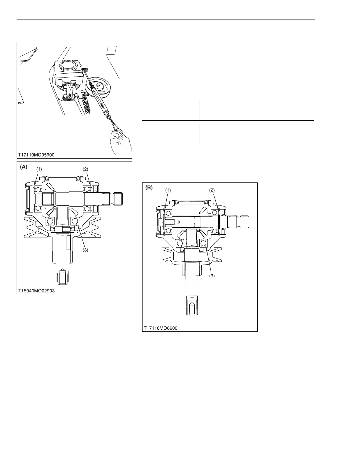
Turning Torque of Pinion Shaft
1. Remove the mower belt, and reassemble the gear box to the
mower deck.
2. Wind a string around the pinion shaft and set a spring balance (or
push-pull gauge) to the tip of the stri ng, and then slowly pull the
spring balance horizontally to measure the turning force.
3. If the measureme nt exc eeds the fac tory spec ific ation, check the
bearing and gears and adjust the adjusting shims (1), (2), (3).
Less than 117.7 N
Turning force Factory spec.
12.0 kgf
26.5 lbs
Turning torque Factory spec.
Less than 1.47 N·m
0.15 kgf·m
1.08 ft-lbs
(Reference)
• Thickness of adjusting shims (1), (2) : 0.2 mm (0.0079 in.)
0.3 mm (0.0118 in.)
• Thickness of adjusting shims (3) : 0.1 mm (0.0039 in.)
0.2 mm (0.0079 in.)
(1) Adjusting Shim
(2) Adjusting Shim
(3) Adjusting Shim
S-16
(A) RCK54-24B-EC, RCK60-24B-EC,
RCK60-27B-EC
(B) RC60-24BR, RC60-27BR
W1019836
Page 55

RCK54/60-24B-EC · RCK60-27B-EC · RC60-24/27BR, WSM
KiSC issued 11, 2006 A
ROTARY MOWER
Backlash between Bevel Gears
1. Remove the gear box cap (3).
2. Place fuses the 19T bevel gear (2) on the pinion shaft (5).
3. Turn the pinion shaft.
4. Take out the fuses, and measure the t hickness of fuses with an
outside micrometer. (Backlash equal thickness of fuse)
5. If the backlash exceeds the allowable limit, adjust with shims (1),
(4), (6).
Backlash between
bevel gears
RCK54-24B-EC
Factory
spec.
Allowable limit
RCK60-24B-EC
RCK60-27B-EC
RC60-24BR
RC60-27BR
0.10 to 0.20 mm
0.0039 to 0.0079 in.
0.13 to 0.25 mm
0.0051 to 0.0098 in.
0.40 mm
0.0157 in.
(Reference)
• Thickness of adjusting shims (1), (4) : 0.2 mm (0.0079 in.)
0.3 mm (0.0118 in.)
• Thickness of adjusting shims (6) : 0.1 mm (0.0039 in.)
0.2 mm (0.0079 in.)
(1) Shim
(2) 19T Bevel Gear
(3) Gear Box Cap
(4) Shim
(5) Pinion Shaft
(6) Shim
(A) RCK54-24B-EC, RCK60-24B-EC,
RCK60-27B-EC
(B) RC60-24BR, RC60-27BR
W1020126
S-17
Page 56

EDITOR
KUBOTA FARM & INDUSTRIAL MACHINERY SERVICE, LTD.
64, ISHIZU-KITAMACHI, SAKAI-KU, SAKAI-CITY, OSAKA, 590-0823, JAPAN
PHONE : (81)72-241-1129
FAX : (81)72-245-2484
E-mail : [email protected]
KUBOTA Corporation
:
Printed in Japan 2006. 11, S, EI, EI, e Code No.9Y011-17110
2001. 02, S, EI, EI, e
 Loading...