

WSE DigiReader DR4205, DigiReader DR4238, DigiReader DR4205K, DigiReader DR4205GM, DigiReader DR4205W Installation And Operation Manual
...
DigiReader Series
INTRODUCTION
The DigiReader DR4200 Series Digital Proximity Readers (DigiReaders) are security devices that
reads digital credentials at ranges from 1 to 36 inches (2½ to 91 cm) depending upon the model and
the environmental conditions. DR4200 Series DigiReaders are bi-directional, so that a credential can
be read from either side of the sensor. DR4200 Series DigiReaders are used with the NexSentry 4100
Family, SE818SC and SE422 ACUs operating as stand-alone devices or in conjunction with a
NexSentry Manager, an SE6000 (a NexSentry Command Center NSCC) or an SE5850, (WSE
access control host systems). Connection between DigiReaders and an ACU is over the WSE
proprietary S-Net interface or over a Wiegand interface to a Wiegand ACU. The Wiegand data can
be either 26- or 34-bit Wiegand standard.
CAUTION 1. Read this manual carefully before attempting to wire in place a DR4200 Series
DigiReader. The warranty is void if damage occurs to the unit as a result of
incorrect wiring.
CAUTION 2. The information in this manual is not intended to conflict with the building codes,
electrical codes, fire codes, or safety codes required for any given installation.
In all cases, the prevailing building codes must take precedence.
P/N 6600025, REV. BX 1
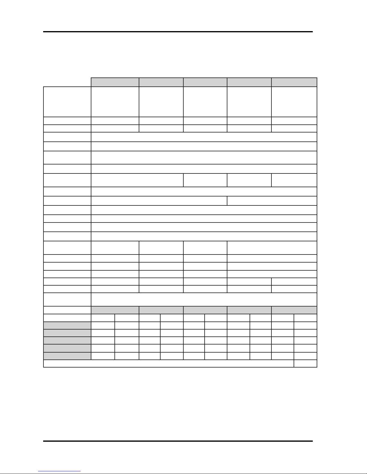
GENERAL SPECIFICATIONS
1024RD 3024RD *seireS5024RD 6224RD 8324RD
DigiReader Series
/tsoctsewoL
noitpircseD
)sehcnI(snoisnemiD2.0x7.0x8.12.1x5.7x8.1* 3.1x0.9x8.719.1x8.31x9.52
).mC(snoisnemiD5.0x8.1x5.40.3x0.91x5.4* 2.3x9.22x2.548.4x0.53x8.56
ycneuqerFtimsnarTnoitarepoxelpudlluf,zhK041
ycneuqerFrevieceRzHk07
revieceR
noitaludomeD
elcyCdaeRdraCcesm001
ecruoSrewoPAm08nahtssel,CDV42-61*
aivderewoPeriwriapdetsiwtten-S
noitapissiDrewoPsttaw2nahtsseL sttaw71nahtsseL
srellortnoC224ES,CS818otlA,seireS0014yrtneSxeN
rellortnocotecafretnI snoitacinummocteN-S;584-SR,)dedleihs,GWA22(riapdetsiwtlauD
srotacidnIelbammargorp,)der-wolley-neerg(roloc-irtelgniS
noitcetorPrepmaTseY
ytidimuH
(erutarepmeT)F°051ot13-051ot13-* 041ot4(erutarepmeT)C°66ot53-66ot53-* 06ot02-
tnemnorivnEylnoesuroodnIesuroodtuO/roodnI* esuroodtuOdnaroodnI
).sbL(thgieW52.01<*5<01<
)smargK(thgieW211.054.0<*3.2<5.4<
tnailpmocADA
egnaRdaeR.xaM
)stinU()sehcnI().mC()sehcnI().mC()sehcnI().mC()sehcnI().mC()sehcnI().mC(
yeKardauQ5.1otpu8.3otpu3otpu6.7otpu4otpu01otpu31otpu33otpu22otpu55otpu
yeKxeN5.1otpu8.3otpu3otpu6.7otpu4otpu01otpu31otpu33otpu22otpu55otpu
yeKaruD5.1otpu8.3otpu4otpu01otpu6otpu51otpu22otpu55otpu63otpu19otpu
etaMyeK1otpu5.2otpu1otpu5.2otpu2otpu5otpu21otpu03otpu51otpu83otpu
gaTaruD1otpu5.2otpu1otpu5.2otpu2otpu5otpu01otpu52otpu51otpu83otpu
1024RD 3024RD 5024RD 6224RD 8324RD
rofredaertsellams
'hctiwsthgil'
sgnitnuomepyt
langis)KSP(yeKtfihS-esahP
%09ot%01
)gnisnednoc-non(
ytimixorplatigiD
roodrofredaer
snoillum
%09ot%01
gnisnednoc
sutatssseccaetacidniotsrotacidni
sngisedtnereffiD
sgnitnuomdna
*seiresnihtiw
*gnisnednoc%09ot%01
ytimixorplatigiD
htiwredaer
daerdesaercni
egnar
6.0,CDV42-61
lanimonpma
.noitallatsnifotnemnorivnelacisyhpnognidnepedyravyamegnardaermumixaM
ytimixorplatigiD
htiwredaer
daermumixam
egnar
7.0,CDV42-61
lanimonpma
lausivdnaelbidua,sseccaeerf-sdnah:edulcnisseccadelbasidgnisaerofserutaeflaicepS;seY
*See Table 1A for details on DR4205 Readers
2 P/N 6600025, REV. BX
Table 1: Digital Reader Specifications
DigiReader Series
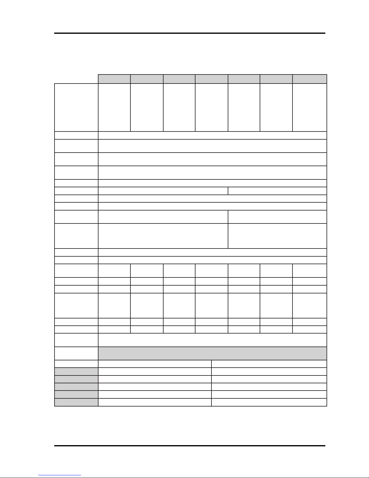
DR 4205 SERIES SPECIFICATIONS
5024RD E5024RD MG5024RD K5024RD W5024RD EW5024RD MGW5024RD
noitpircseD
snoisnemiD)mc2.3x6.41x5.31("72.1x"47.5x"3.5
timsnarT
ycneuqerF
revieceR
ycneuqerF
revieceR
noitaludomeD
elcyCdaeRdraCcesm001
ecruoSrewoPAm08nahtssel,CDV42-61 Am08nahtssel,CDV42-8
aivderewoPeriwriapdetsiwtten-S
noitapissiDrewoPsttaw2nahtsseL
srellortnoC224ES,CS818otlA,seireS0014yrtneSxeN
otecafretnI
rellortnoc
srotacidnIelbammargorp,roloc-irtelgniS
noitcetorPrepmaTseY
ytidimuH
(erutarepmeT)F°051ot91051ot13-051ot91051ot13-051ot91051ot13-051ot91
erutarepmeT)C°(66ot7-66ot53-66ot7-66ot53-66ot7-66ot53-66ot7-
tnemnorivnE
)secnuO(thgieW51429151214291
)smarG(thgieW024276235024043276235
tnailpmocADA
mumixaM
egnaRdaeR
)stinU()sehcnI()sretemitneC(
yeKardauQ4otpu01otpu
yeKxeN4otpu01otpu
yeKaruD6otpu51otpu
etaMyeK2otpu5otpu
gaTaruD2otpu5otpu
latigiD
ytimixorp
redaer
zHk07
snoitacinummoc
%09ot%0
gnisnednoc
esuroodnI
ylno
latigiD
ytimixorp
rofredaer
esulanretxe
noitarepoxelpudlluf,zhK041
langis)KSP(yeKtfihS-esahP
%001ot%5
gnisnednoc
dezirehtaeW
-hsalpsdna
roffoorp
esuroodtuo
sutatssseccaetacidniot
latigiD
ytimixorp
htiwredaer
foytilibapac
ssalggnieb
detnuom
%09ot%01
gnisnednoc
esuroodnI
ylno
latigiD
ytimixorp
htiwredaer
detargetni
foorpretaw
rofdapyek
dnaroodni
esuroodtuo
teN-S;584-SR,)dedleihs,GWA22(riapdetsiwtlauD
%001ot%5
gnisnednoc
dezirehtaeW
-hsalpsdna
roffoorp
esuroodtuo
dnageiW
ytimixorp
redaer
%09ot%01
gnisnednoc
esuroodnI
ylno
sledoM5024RDllA
dnageiW
ytimixorp
rofredaer
esulanretxe
d'qeRtinUecafretnI
deriuqertinUecafretnI
%09ot%5
gnisnednoc
dezirehtaeW
-hsalpsdna
roffoorp
esuroodtuo
dnageiW
ytimixorp
htiwredaer
foytilibapac
ssalggnieb
detnuom
dnageiWyrtneSxeN.seireS0014yrtneSxeN
-SR,)dedleihs,GWA22(riapdetsiwTlauD
-5tib-43ro-62;snoitacinummocteN-S;584
dnageiWyrtneSxeN;dradnatsdnageiWeriw
%09ot%01
gnisnednoc
esuroodnI
ylno
srotacidnilausivdnaelbidua,sseccaeerf-sdnah:edulcnisseccadelbasidgnisaerofserutaeflaicepS;seY
P/N 6600025, REV. BX 3
Table 1A: DR4205 Series Specifications

BASIC OPERATION
DigiReaders emit a low-level 140-kHz field. When a digital credential card is placed in this field, a
digital chip embedded in the key uses the fields energy to become activated. Once activated, the
key responds by broadcasting a 70-kHz signal, modulated with a key-specific code sequence, back
to the reader. The reader receives this signal and converts it to a digital code which is then sent to
the Controller. The Controller identifies the digital credential according to its code and makes either
an access granted or an access denied decision.
DR4205K (/W) has a keypad on the face of the DigiReader. The key pad is used to enter the users
Personal Identification Number (PIN). (See the appropriate Controller or security management
system manual for details on PIN assignment.)
The user may enter his or her own PIN. The LED turns amber, and then the user presents a digital
credential; or the user may first present the key, the LED turns amber, and then the user enters the
PIN. The time allotted for this procedure is defined by the PIN GRACE PERIOD which is set with
the Controller SYSTEM command. (See the appropriate Controller or security management system
manual for information on setting this parameter.) If an error is made in entering the PIN, the user
may press the "*" key to clear the keypad and begin entry again.
DigiReader Series
The keypad versions can be configured for keypad-only use or credential-only use. Refer to your
controller manual or security management system manual for details on setup and configuration.
DR4200K is just the keypad part of the DR4205K.
LED OPERATION
LED (S-NET OPERATION)
When the DigiReader is on line, the LED is red during the ready state. The TUNE command is used
to specify LED and beeper behavior when a valid key is presented. An equivalent of the tune
command may be found in each WSE security management system system.
DigiReaders have a single three-color LED that can be controlled by the Controller. If power is applied
to the unit when not connected to a Controller, or improperly configured at the Controller, the LED
acts as follows: Flashes red four times in four seconds, changes to steady amber for four seconds
and then turns off for 52 seconds. When a key is presented, the sensor beeps four times, and the
LED flashes amber until the key is moved out of range. The flashing red, steady amber, off cycle
then resumes and repeats indefinitely while power is supplied.
4 P/N 6600025, REV. BX
DigiReader Series
LED (WIEGAND OPERATION)
The LED is controlled to be red or green by the level of the Wiegand LED control input.
120-OHM TERMINATION JUMPER
The internal jumper places 120 ohms of resistance between Data A and Data B for proper end-ofline termination. Install the jumper only if the DR4200 Series DigiReader is the last device on the
cable. If you are using:
5HDGH U
'5.
'5
'5
'5(
'5:
'5*0
'5.
'5)0
7HUPLQDWLR Q
-XPSHU
:
'5 :
Table 2: Termination Jumpers
If you are using the DR4208, DR4226 or DR4238, an external 120 ohm, 1/4 watt resistor must be
used. There is no internal jumper on these models. The jumper is only available on surface mount
technology (SMT) models.
INTERNAL INTERFACE CABLE
An attached cable provides the connection from the printed-circuit assembly and keyboard to the
access control unit wiring on all DigiReaders except for the DR4201, DR4208, DR4226 and the
DR4238. The cable is color coded as follows:
ROLOC NOITCNUF STNEMMOC
deRCDV82+ot61+)lanimoN(
kcalBnruteRCD
neerGAteN-SslenaplortnocsseccaESWhtiwesuroF
etihWBteN-SslenaplortnocsseccaESWhtiwesuroF
eulB0ataDslenaplortnocsseccadnageiWhtiwesuroF
egnarO1ataDslenaplortnocsseccadnageiWhtiwesuroF
wolleY0DELslenaplortnocsseccadnageiWhtiwesuroF
nworB1DELslenaplortnocsseccadnageiWhtiwesuroF
dleihSdleihSlangiS
slenaplortnoc
sseccadnageiWhtiwdesunehwnruteRCDoteiT
P/N 6600025, REV. BX 5
Table 3: Internal Interface Cable
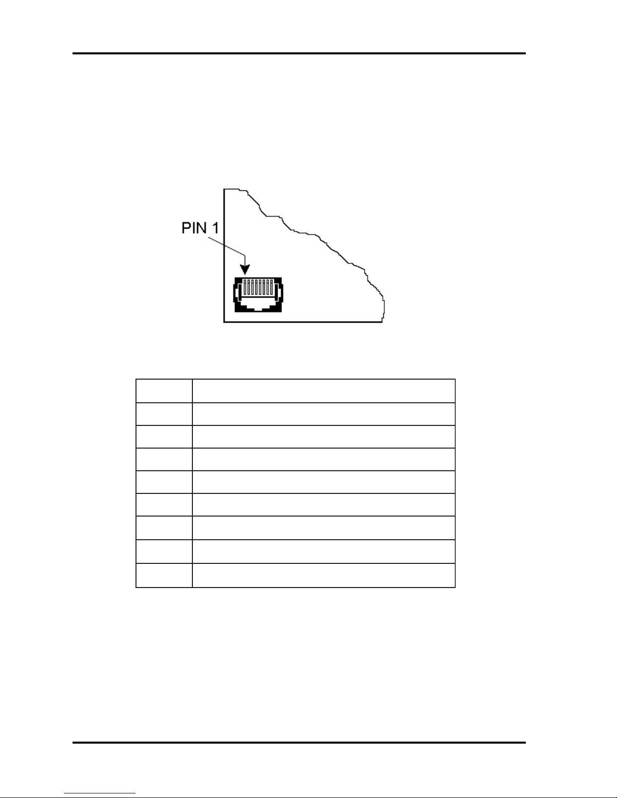
DR4201 READER INTERFACE
The DR4201 reader is connected into the system for S-Net and Wiegand input and output via an
RJ45-telephone-jack-style 8-pin connector J1, located in the bottom left corner of the PC board, as
shown in figure 1, and described in table 4, below:
DigiReader Series
Figure 1: DR4201 RJ45 S-Net/Wiegand 8-pin Connector
niP1JnoitpircseD
1CDV42+
2AteN-S
3BteN-S
4nruteRV42
5)tceles2WpartS(0ataDdnageiWrodleihS
6
7
8
Table 4: DR4201 RJ45 S-Net/Wiegand Signal Pin Descriptions
1ataDdnageiW
0DELdnageiW
1DELdnageiW
NOTE: A mating connector is supplied with each DR4201 reader, but a crimping tool (not supplied)
is required to crimp the connections.
6 P/N 6600025, REV. BX
DigiReader Series
RECOMMENDED S-NET CABLE
The type of cable used for the S-Net will depend on the total length and the number of devices
connected. Table 5 lists WSE recommended cables.
SWITCHES
ERUTCAFUNAM
.tF0004<rewoPdnaataD
.tF005<rewoPdnaataD
.tF005>ylnOataD1489nedleBdedleihSriaP-1GWA42
.tF005>ylnOrewoP
yarG/971WS
2559nedleB
9601nedleB
1439nedleB
2431nedleB
3439nedleB
elbaC&eriWtsewhtuoS
LACISYHP
NOITPIRCSED
ataD:rotcudnoC2
rewoP:rotcudnoC2
dedleihSriaP-2
rotcudnoC2
Table 5: Recommended S-Net Cable
EGUAG
GWA22
GWA61
GWA81
GWA61
GWA81
GWA61
GWA41
There are two switches on most DR4200 Series DigiReader printed circuit board, as follows,
(refer to Figure 2):
Switch SW1 is used to select between the S-Net or Wiegand operating modes.
Switch SW2 is used to set the S-Net address.
The DR4201 reader has a 5-position DIP-switch S1, which combines the functions of the rotary
address switches S1 and S2 used by the other DR4200 Series DigiReaders. This is described in
the DR4201 ADDRESS DIP-SWITCH section, below.
P/N 6600025, REV. BX 7
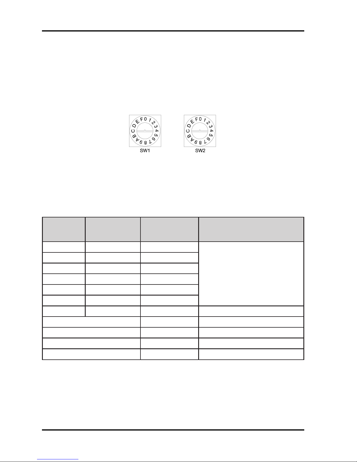
DIGIREADER ADDRESS
Each DigiReader must have a unique address. SW1 is used to select the special reader modes
of operation, (as shown in Table 6). SW1 should be set to 0 for S-Net operation and F for Wiegand
operation. SW2 is set in the factory to 1 but may be set to an address between 1 and 15 (F). Valid
addresses may be limited by the controller; (see the appropriate controller manual).
Figure 2: Address Switch
When used with an SE422 controller, addresses 01 and 02 should be assigned to nodes 13/15 and
14/16, respectively.
DigiReader Series
*1WS
lamroN(
(yeK/NIP
)edoM
06ro5,41
06ro5,42
.. .
.. .
06ro5,4E
06ro5,4F
**8**EroD,C**0lamiced61sserddateN-S
FA tib-62dnageiW
FB tib-43dnageiW
FE edoMomeD
FF ***edoMtseTFR
*1WS
2WS NOITCNUF
edoM)
Table 6: Valid Switch Settings for Switches 1 and 2
(* See the DR4205K SPECIAL OPERATING FEATURE section, below)
(** See next page for S-Net address 16, Normal or PIN/Key explanation)
(*** See the TESTING THE DIGIREADER LOCATION section, below)
sesserddateN-S
lamicedaxehF-1
)lamiced51-1(
8 P/N 6600025, REV. BX
 Loading...