

IP camera tester
User Manual
(V01.00)

Thank you for purchasing the IP camera tester. Please read the manual before using the IP camera
tester and use properly.
For using the IP camera tester safely, please first read the「Safety Information」carefully in the
manual.
The manual should be kept well in case of reference.
Keep the S/N label for after-sale service within warranty period. Product without S/N label will
be charged for repair service.
If there is any question or problem while using the IP camera tester, or damages occurred on the
product, please contact our technical Department.

Content
1 .Safety information--------------------------------------------------------------------------------------------------1
2. IP Camera Tester Introduction------------------------------------------------------------------------------------2
2.1 General------------------------------------------------------------------------------------------------------- 2
2.2 Features------------------------------------------------------------------------------------------------------ 2
2.3 Packing list---------------------------------------------------------------------------------------------------6
2.4 Function interface-------------------------------------------------------------------------------------------7
3. Operation-----------------------------------------------------------------------------------------------------------11
3.1 Installing the Battery--------------------------------------------------------------------------------------11
3.2 Instrument connection------------------------------------------------------------------------------------ 12
3.2.1 IP camera connection----------------------------------------------------------------------------------- 12
3.2.2 Analog camera connection-----------------------------------------------------------------------------13
3.2.3 HD Coaxial camera connection----------------------------------------------------------------- 14
3.2.4 HDMI IN ( *Optional )---------------------------------------------------------------------------15
DVR or other device’s HDMI in port connect to tester’s HDMI in port, the meter will display
input image----------------------------------------------------------------------------------------------- 15
3.3 OSD menu-------------------------------------------------------------------------------------------------- 15
3.3.1 Lite mode & Normal mode---------------------------------------------------------------------- 15
3.3.2 Drop-down Menu--------------------------------------------------------------------------------- 19
3.3.3 Short cut-menu------------------------------------------------------------------------------------ 20
3.3.4 Screen capture------------------------------------------------------------------------------------- 21
3.3.5 TesterPlay------------------------------------------------------------------------------------------ 21
3.3.6 Rapid video---------------------------------------------------------------------------------------- 23
3.3.7 IP discovery---------------------------------------------------------------------------------------- 24
3.3.8 Rapid ONVIF test--------------------------------------------------------------------------------- 25
3.3.9 IP camera test-------------------------------------------------------------------------------------- 38
3.3.10 HDMI IN ( *Optional )----------------------------------------------------------------------- 41

3.3.11 Video monitor test------------------------------------------------------------------------------- 45
3.3.12 Color-bar generator (TV OUT)---------------------------------------------------------------- 53
3.3.13 SDI Camera Test ( *Optional )-------------------------------------------------------------- 54
3.3.14 CVI camera test ( *Optional )--------------------------------------------------------------- 55
3.3.15 TVI camera test ( *Optional )----------------------------------------------------------------61
3.3.16 AHD camera test ( *Optional )-------------------------------------------------------------- 63
3.3.17 Network tool------------------------------------------------------------------------------------- 65
(1)IP address scan------------------------------------------------------------------------------------65
(2)PING Test----------------------------------------------------------------------------------------- 65
(3)Network test (Ethernet bandwidth test)------------------------------------------------------- 66
(4)Port Flashing-------------------------------------------------------------------------------------- 69
(5)DHCP server-------------------------------------------------------------------------------------- 70
(6)Trace route---------------------------------------------------------------------------------------- 70
(7)Link monitor-------------------------------------------------------------------------------------- 71
3.3.18 Rapid IP Discovery------------------------------------------------------------------------------ 72
3.3.19 PoE power / DC12V 2A and DC 5V 2A USB power output------------------------------ 72
3.3.20 Cable Test---------------------------------------------------------------------------------------- 73
3.3.21 RJ45 cable TDR test---------------------------------------------------------------------------- 74
3.3.22 Cable Search ( *Optional )----------------------------------------------------------------- 77
3.3.23 TDR cable test ( *Optional )----------------------------------------------------------------- 78
3.3.24 PoE Voltage test--------------------------------------------------------------------------------- 81
3.3.25 12V power input test---------------------------------------------------------------------------- 82
3.3.26 Digital Multi-meter ( *Optional )----------------------------------------------------------- 83
3.3.27 Optical power meter ( *Optional )---------------------------------------------------------- 90
3.3.28 Visual Fault Locator ( *Optional )---------------------------------------------------------- 92
3.3.29 Audio Record------------------------------------------------------------------------------------ 94
3.3.30 Data monitor------------------------------------------------------------------------------------- 94
3.3.31 Audio player--------------------------------------------------------------------------------------95
3.3.32 Media Player------------------------------------------------------------------------------------- 95

3.3.33 RTSP Player-------------------------------------------------------------------------------------- 96
3.3.34 Hik test tool---------------------------------------------------------------------------------------97
3.3.35 Dahua test tool----------------------------------------------------------------------------------100
3.3.36 Update------------------------------------------------------------------------------------------- 103
3.3.37 Office-------------------------------------------------------------------------------------------- 104
3.3.38 LED Flashlight--------------------------------------------------------------------------------- 104
3.3.39 Browser------------------------------------------------------------------------------------------105
3.3.40 Notepad:----------------------------------------------------------------------------------------- 105
3.3.41 System Setting---------------------------------------------------------------------------------- 106
3.3.42 File explorer------------------------------------------------------------------------------------ 110
3.3.43 Theme--------------------------------------------------------------------------------------------112
3. 4 Audio test------------------------------------------------------------------------------------------------ 114
3.5 PoE power output---------------------------------------------------------------------------------------- 115
3.7 DC12V 2A power output------------------------------------------------------------------------------- 116
4. Specifications---------------------------------------------------------------------------------------------------- 118
4.1 General Specifications---------------------------------------------------------------------------------- 118
4.2 Multi-meter specifications------------------------------------------------------------------------------ 121
4.3 Optical power meter specifications-------------------------------------------------------------------- 123
4.4 Visual fault locator specifications--------------------------------------------------------------------- 124

Page.1.
1 .Safety information
◆ The tester is intended to use in compliance with the local rules of the electrical usage and avoid to
apply at the places which are inapplicable for the use of electrics such as hospital, gas station etc.
◆ To prevent the functional decline or failure, the product should not be sprinkled or damped.
◆ The exposed part of the tester should not be touched by the dust and liquid.
◆ During transportation and use, it is highly recommended to avoid the violent collision and vibration
of the tester, lest damaging components and causing failure.
◆Don’t leave the tester alone while charging and recharging. If the battery is found severely hot, the
tester should be powered off from the electric source at once. The tester should not be charged over 8
hours.
◆ Don’t use the tester where the humidity is high. Once the tester is damp, power off immediately and
move away other connected cables.
◆ The tester should not be used in the environment with the flammable gas.
◆ Do not disassemble the instrument since no component inside can be repaired by the user. If the
disassembly is necessary indeed, please contact with the technician of our company.
◆ The instrument should not be used under the environment with strong electromagnetic interference.
◆ Don’t touch the tester with wet hands or waterish things.
◆ Don’t use the detergent to clean and the dry cloth is suggested to use. If the dirt is not easy to remove,
the soft cloth with water or neutral detergent can be used. But the cloth should be tweaked
sufficiently.
About Digital Multi-meter
◆ Before using, you must select the right input jack, function and range.
◆ Never exceed the protection limit values indicated in specifications for each range of measurement.
◆When the tester is linked to a measurement circuit, do not touch unused terminals.
◆Do not measure voltage if the voltage on the terminals exceeds 660V above earth ground.
◆At the manual range, when the value scale to be measured is unknown beforehand, set the range
selector at the highest position.
◆Always be careful when working with voltages above 60V DC or 40V AC, keep fingers behind the
probe barriers while measuring.

Page.2.
◆Never connect the meter with any voltage source while the function switch is in the current,
resistance, capacitance, diode, continuity, otherwise it will damage the meter.
◆Never perform capacitance measurements unless the capacitor to be measured has been discharged
fully.
◆Never measure any of resistance, capacitance, diode or continuity measurements on live circuits.
Visual laser sources
When you turn on visual laser sources, please don’t stare at it, or will damage to eyes
When not using it, please turn it off and cover the protective cap .
2. IP Camera Tester Introduction
2.1 General
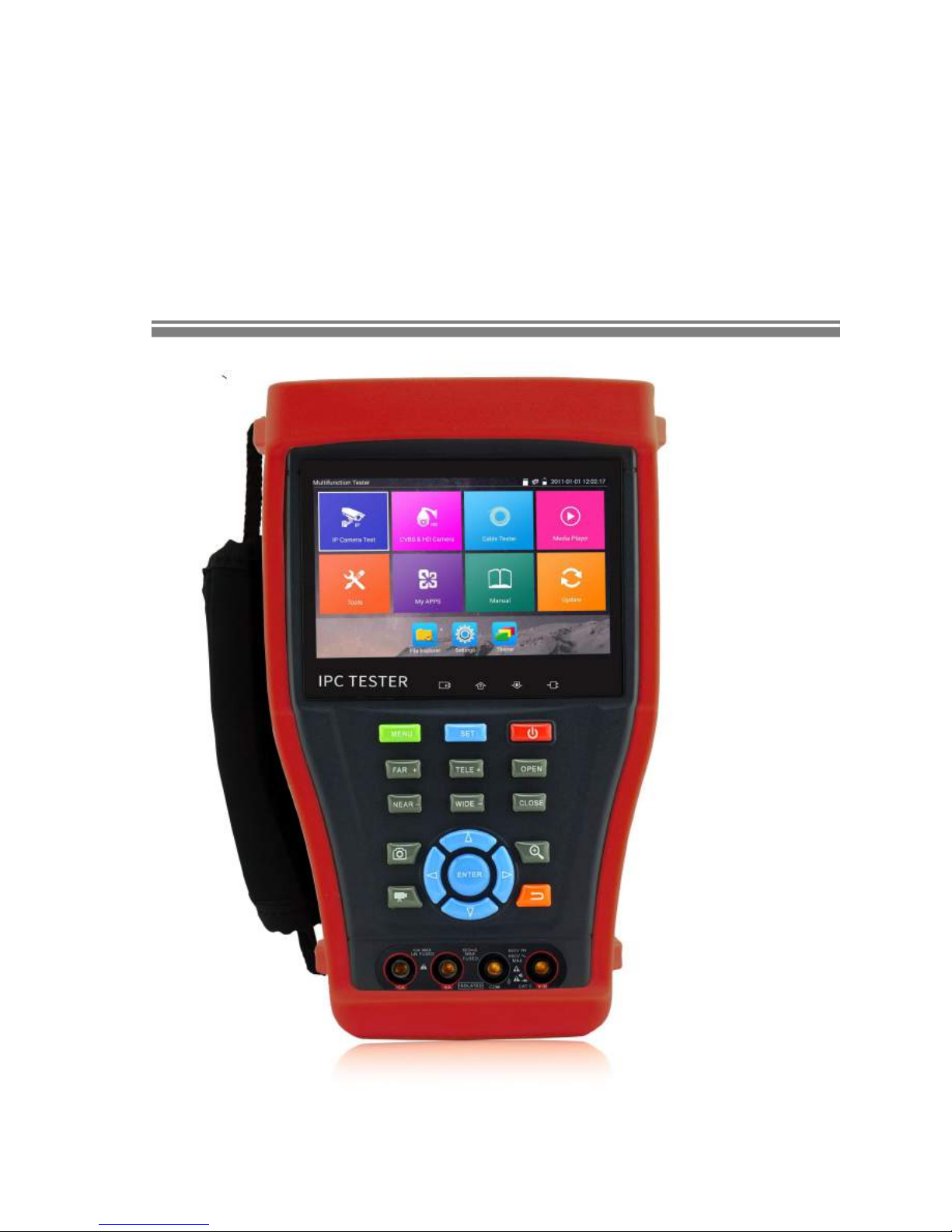
The 4.3 inch IPS touch screen IP camera monitor is designed for maintenance and installation of IP
cameras, analog cameras, TVI, CVI AHD, SDI cameras, as well as testing 4K H.264 /4k H.265 camera
by mainstream, The 960x540 resolution enables it to display network HD cameras and analog cameras
in high resolution. The unit supports many ONVIF PTZ and analog PTZ control. The combination of
touch screen and key buttons make the IP camera tester very user- friendly.
The tester is also a great tool for Ethernet network testing. It can test PoE power voltage, PING, and IP
address searching. You can use the blue cable tracer to locate individual connected cables from a bundle
of cables. Test LAN cable for proper connection termination. Other functions include providing 24W
PoE power to your camera, HDMI IN and out, CVBS loop test , testing IP and analog at the same time,
LED Flashlight, DC 12V 2A power output and much more. Its portability, user-friendly design and
many other functions make the IP tester an essential tool for all installers or technicians.
2.2 Features
New 4.3 inch IPS touch screen cctv tester ,960*540 resolution
4 K H.264 & H .265 display image by mainstream
IP and analog testing at the same time
In HDMI IN mode, It can converter test from analog to digital with dual test window IP &
HDMI IN or Analog & HDMI in * (Optional)

Page.3.
RJ45 cable TDR test and cable quality test, to test cable pair status, length, attenuation
reflectivity, impedance, skew and other parameter.
Screen capture, long press the key “enter”, can capture screen interface and save it in any time
12V power input test
“TesterPlay” app, support Tester, PC and mobile phone display at the same time. The android
version mobile phone install “TesterPlay ” app, or install VLC player in the PC, can real-time
receiving screen information from the tester
Screen management, change function’s icons order, create new directory.
Themes: Lite and normal model can select , change the icons and desktop background ,change
sliding effect etc
Built in Wi-Fi ,display image from the wireless camera , create WIFI hotspot
Rapid video, auto scan the IP camera address, by one key to view the image.
Screen lock : password lock and pattern lock are optional
Office, quick office app (support excel, word, ppt format) doc. Editable
Rapid IP scan , auto scan whole network or other network device ‘s IP address
CVBS loop test , tester can receive and send the color bar generator ,to check BNC cable
Traffic monitoring of the tester "LAN port", display network port or WIFI connection real-time
upload and download speeds and other network parameters.
Drop-down menu : PoE power switch ,IP setting, WLAN switch , HDMI IN functions etc screen
lock, password lock screen or pattern lock
IP discovery, no need to know the first two digits of camera’s IP address , it can auto-scan the
whole network segment IP, and auto-modify tester’s IP address
Rapid ONVIF, search camera quickly, auto log in and display image from the camera, activate
Hikvision camera.
Hik test tool app is designed for activating and debugging Hikvision camera, can auto-identify
unactivated hikvision camera, also can display image from the Hikvision camera.
DH test tool app is design for Dahua Camera test, and modify IP, user name and password
parameters etc

Page.4.
ONVIF camera test, support 4K.
It is used unique hardware decoding, display image from the 4K camera via mainstream.
You can select sub-stream to test higher resolution camera
ONVIF IP camera video testing.
Compatible with H.265/H.264/MPEG4/MJPEG IP cameras, such as Dahua, HIKVISION, and
ACTI Customized service is available.
Built in Wi-Fi, can receive image from wireless camera, as well as ONVIF and customized IP
cameras.
SDI Digital camera image display, record and screen snapshot * (Optional)
HD CVI camera image display, zoom, video record and playback ,Coaxial PTZ control and call
camera OSD menu * (Optional)
HD TVI camera image display, zoom, video record and playback ,Coaxial PTZ control and call
camera OSD menu * (Optional)
AHD camera image display, zoom, video record and playback, Coaxial PTZ control and call
camera OSD menu * (Optional)
HDMI signal output, supports up to 1080P.
Analog camera image display, auto adapt and display the video format of NTSC/PAL
Support more than 30 protocols, such as PELCO-P,PELCO-D,SAMSUNG etc
Video image digital zoom to view the image in greater detail.
Snapshot function allows you to save the current image as a JPG file in the SD card.
Built in enhanced image generator, send the color, pure blue and black image, test monitor
transmission channel and debug display device, observe whether there are light spots or black
spots on the monitor
LED Flashlight.
8GB Micro SD card included.
LCD screen brightness/contrast/color Saturation adjustable
Visual fault locator, to test fiber’s bending and breakage * (Optional)

Page.5.
Optical power meter, test fiber loss and value * (Optional)
Digital Multi-meter , DC and AC voltage measurement, Resistance measurement Continuity test,
Diode measurements, Capacitance measurement * (Optional)
Video level meter PEAK video signal level, SYNC signal level, Color burst chroma level
measurement,test video signal attenuation * (Optional)
Cable tracer, by sending the audio signal, enables the blue cable tracer tester to find the
connected cable from messy cables * (Optional)
Ping test, PING is the most conventional network debugging tools; it is used for testing if the
connected IP camera or other network equipment’s Ethernet port is working normally and the IP
address is correct.
In digital IP surveillance applications, if the IP camera’s IP address is not known; the device
cannot be used. An IP address scan can quickly search for the connected IP camera or other
network device’s IP address.
The PoE voltage test can test for PoE voltage when a POE switch is supplying POE power to an
IP camera
TDR cable test, test cable open circuit and short-circuit * (Optional)
Cable test , Test LAN cable or telephone cable,UTP cable etc ,cable type and the sequence of
wires will be displayed
Support RS232/RS485,rate 600 ~ 115200bps adjustable
PTZ protocol analysis, control protocol command displays to check RS485 transmission
whether is normal, easy to find the fault device
PTZ control. Pan/tilts the P/T unit, zooms in/out the lens, adjusts the focus, aperture and
sets and the preset position
DC5V 2A power output for USB charging (No USB data exchange, voltage only)
PoE power output, supply temporary power for PoE camera
DC5V 2A power output, as a power bank
Audio input and output, test and output the audio signal
7.4V Lithium Ion Polymer Battery ,Working time lasts 10 hours, after charging for 5 ~6 hours

Page.6.
2.3 Packing list
1). Tester
2). Adaptor DC12V 2A
3) Network cable tester
4) Polymer lithium ion battery (7.4V DC 5000mAh)
5). BNC cable
6). RS485 cable
7). SC,ST connector(Only for optical power meter)
8). Multi-meter test leads one pair of red and black (only for the Multi-meter models)
9). Output Power cable
10). Audio cable
11). TDR alligator clamp (only for TDR models)
12). Safety cord
13). Tool bag
14). Manual
15).8GB SD card
Page.7.
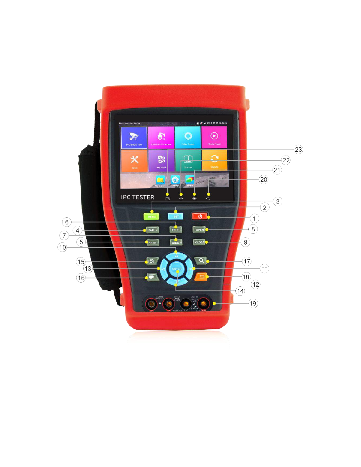
2.4 Function interface
Page.8.
1
Press more than 2 seconds, turn on or off the device ,short press to turn on or off
the menu display
2
Set key
3
Menu key
4
Near focus: Focus the image nearby
5
Far focus: Focus the image faraway
6
TELE: zoom in the image
7
WIDE: zoom out the image
8
Open/set ,Confirm the setting of parameters, open or enlarge the aperture
9
Return/Close : Return or cancel while setting parameters of the menu, close or
decrease the aperture
10
Upward, set function or add parameter. Tilt the PTZ upward
11
Rightward, select the parameter whose value will be changed. Add the value of the
parameter. Pan the PTZ right
12
Confirm key
13
Leftward, select the parameter whose value will be changed
14
Downward, set function or reduce the value of the parameter. Tilt the PTZ
downward
15
Snapshot
16
Video record
17
Open/set ,Confirm the setting of parameters, open or enlarge the aperture
18
Return/Close : Return or cancel while setting parameters of the menu, close or
decrease the aperture
19
Multimeter interface (Optional)
Page.9.
20
The power indicator: it lights green while the tester is powered on by the adapter
21
The data accepted indicator: it lights red while the data is being received
22
The RS485/RS232 data transmission indicator: it lights red while the data is being
transmitted
23
The charge indicator: it lights red while the battery is being charged. As the
charging is complete, the indicator turns off automatically
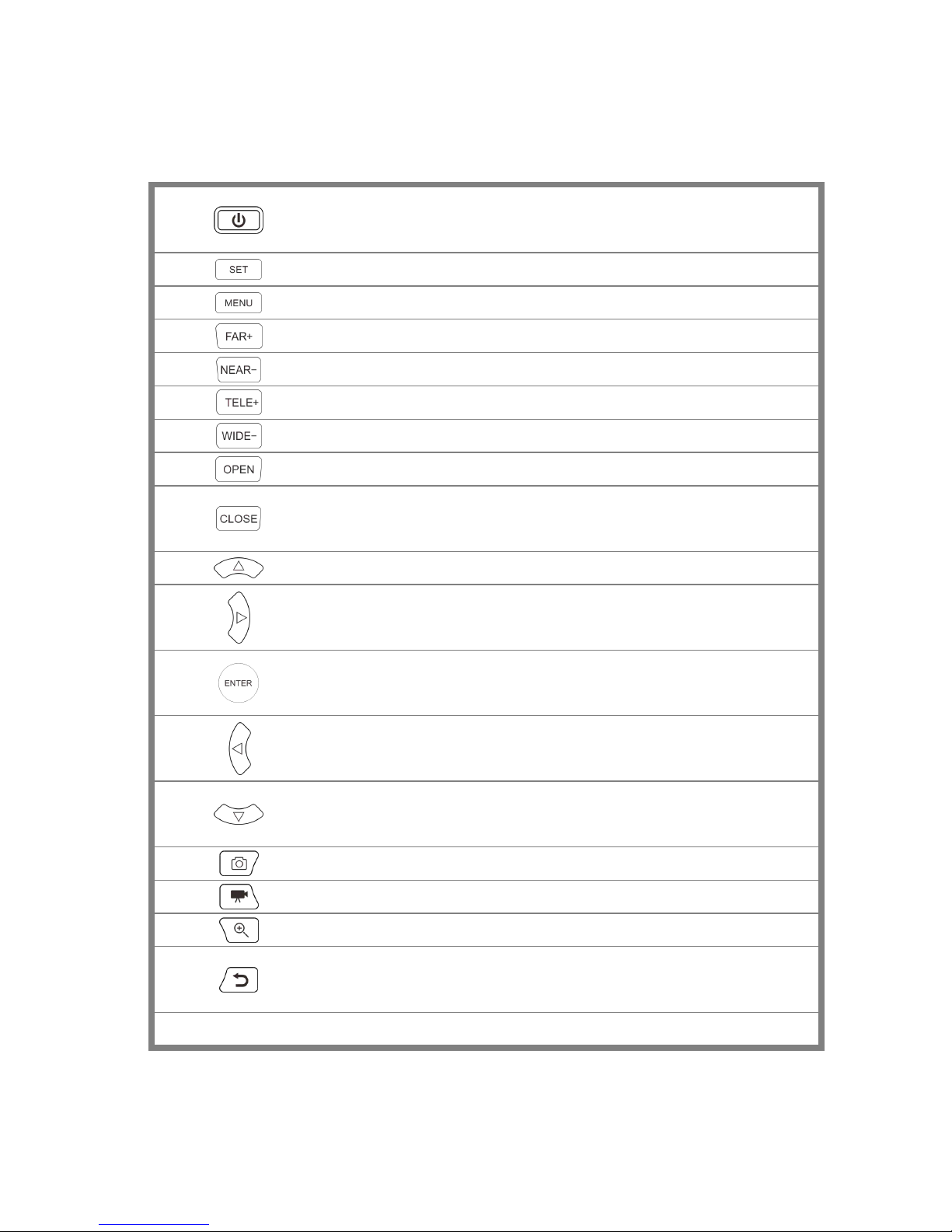
Top interface
Left interface Right interface

Page.10.
24
RS485 Interface: RS485communication for the PTZ
25
RS232 Interface: RS232 communication for the PTZ"HD IN" , AHD /TVI/CVI Coaxial
interface (Optional )
26
DC12V2A power output , for provisional DC power supply
27
TDR cable test interface
28
LED lamp
29
SDI input (BNC interface) (Optional)
30
HDMI input
31
Video image signal output(BNC interface)/cable tracer interface (Optional)
32
Video image signal input(BNC interface)/ AHD,CVI and TVI input (BNC interface)
(Optional)
33
Optical power meter interface (Optional)
34
Visible red laser source emits Interface (Optional)
35
UTP cable port: UTP cable tester port/ Cable tracer port
36
Micro SD card moveable, comes with 8GB, supports up to 32GB
37
Audio input
38
HDMI output interface
39
Audio and earphone output
40
5V2A USB power output , as power bank
41
DC12V2A charging interface
42
PSE power sourcing equipment. Tests PoE voltage
43
PoE power supply output or LAN test port (Use to test PoE or non-PoE IP camera)
Page.11.
3. Operation
3.1 Installing the Battery
The tester has built-in lithium ion polymer rechargeable battery. The battery cable inside battery
cabin should be disconnected for safety during transportation!
Prior to the use of the instrument, the battery cables inside the battery cabin should be well
connected.
Pressing the key continuously can power on or off the tester.
Notice:Pls use the original adaptor and connected cable of the device!
When the battery icon is full or the charge indicator turns off automatically, indicate the battery
charging is completed
Notice: When the Charge Indicator turns off, the battery is approximately 90%
charged. The charging time can be extended for about 1 hour and the charging time within 12
hours will not damage the battery.
Notice :Press the key several seconds to restore the default settings when the
instrument works abnormally.
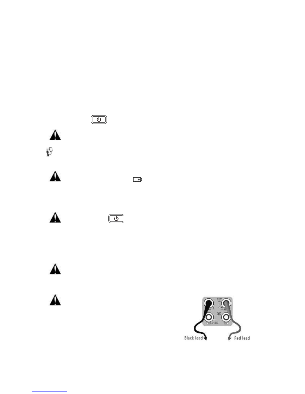
Multi-meter: the red and black multi-meter pen must insert the corresponding port.
Warnings:Instrument communication port is not permitted access circuit voltage over 6V,
otherwise damage the tester.
Warnings:Not allow insert multi-meter pen in the current
terminal to measure voltage
Page.12.
3.2 Instrument connection
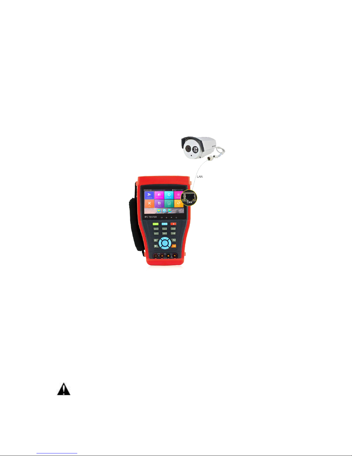
3.2.1 IP camera connection
Power an IP camera with an independent power supply, then connect the IP camera to the IPC tester’s
LAN port, if the link indicator of the tester’s LAN port is green and the data indicator flickers, it means
the IP camera and the IPC tester are communicating. If the two indicators don’t flicker, check if the IP
camera is powered on or the network cable is not functioning properly.
Note:1) If the IP camera requires PoE power, then connect the IP camera to the IP tester’sLAN port .
The tester will supply PoE Power for the IP camera. Click on the icon labeled POE to turn the PoE
Power off or on.
2) If use the tester’s menu to turn off the tester’s PoE power supply, the PoE switch and the power
sourcing equipment are allowed to connect to the tester’s PSE port, and the PoE power will be supplied
to the IP camera by the tester’s LAN port. On this condition, the tester cannot receive data from IP
camera, but the computer connected to the PoE switch can receive the data via the the tester.
Warning: Poe switch or PSE power sourcing equipment only can be connected to tester “PSE
Page.13.
IN” port, otherwise will damage the tester.
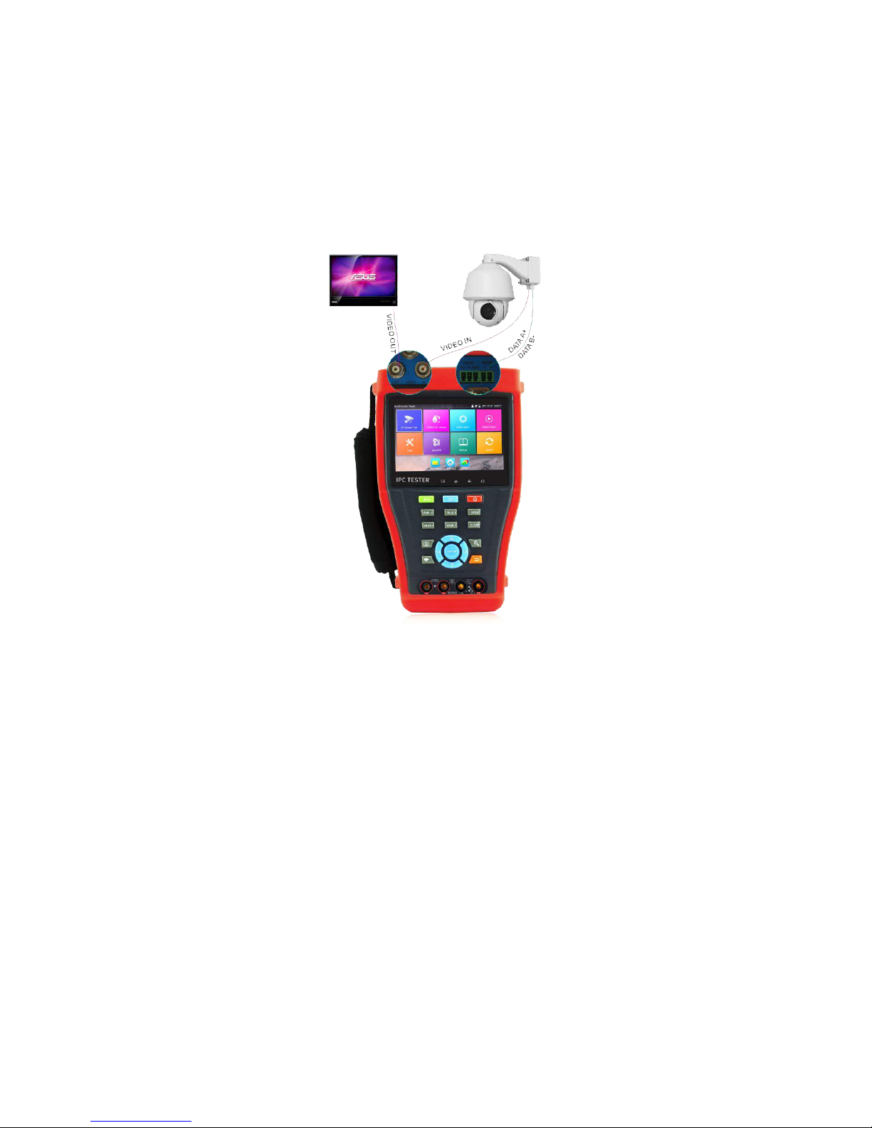
3.2.2 Analog camera connection
(1) Connect the camera's video output to the IP tester’s VIDEO IN. The image will display on the tester
after pushing the PTZ icon
(2) CCTV IP Tester “VIDEO OUT” interface connect to the Video input of monitor and optical video
transmitter and receiver, the image display on the tester and monitor
(3) Connect the camera or the speed dome RS485 controller cable to the tester RS485 interface ,(Note
positive and negative connection of the cable). Support RS232 PTZ controller ,connect the RS232cable
to RS232 interface of the tester
Page.14.
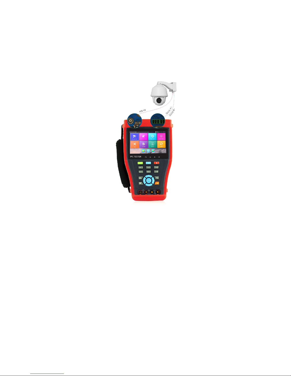
3.2.3 HD Coaxial camera connection
* SDI, CVI, TVI, AHD camera are classified as HD coaxial cameras. Hereby the following instruction
of how to connect SDI camera to the tester is also applied to CVI, TVI, and AHD camera.
(1) Connect the SDI camera's video output to the IP tester’s “SDI IN” interface, the image will display
on the tester. The tester only come with SDI input interface. There is no SDI output interface.
(2) Connect the SDI camera or the speed dome RS485 controller cable to the tester RS485 interface.
Support RS232 PTZ controller; connect the RS232 cable to RS232 interface of the tester.
Page.15.
3.2.4 HDMI IN ( *Optional )
DVR or other device’s HDMI in port connect to tester’s HDMI in port, the meter will display input
image
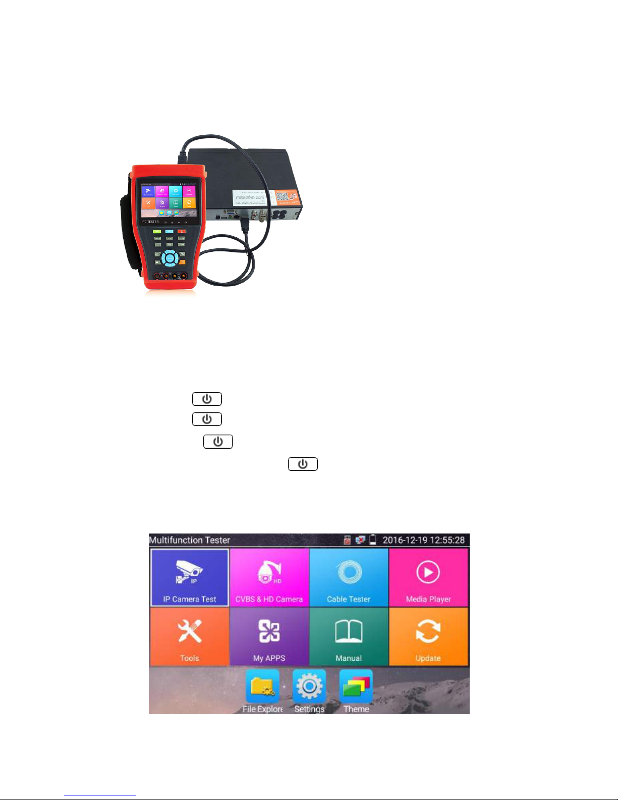
3.3 OSD menu
Press the key 2 seconds to turn on
Press the key 2 seconds to turn off
short press the key to enter sleep mode,press it again to test if tester work abnormally
and cannot be turned off , Press the key several seconds to turn off, the tester reset
3.3.1
Lite mode & Normal mode
Lite mode: You can easy find corresponding apps
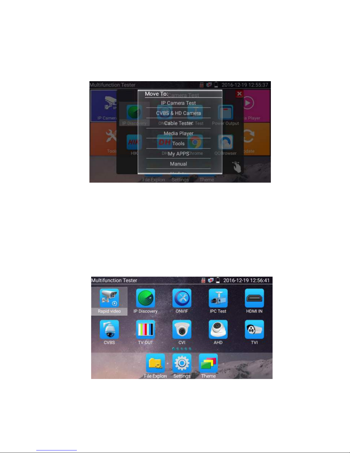
Page.16.
In Lite mode, Press the icon several seconds, can move the icon to other apps
In lite mode, click the finger icon in the lower right corner to release lock icon, move icons and
change function icons sequence.
Normal mode
Tap the screen and slide left or right to change menu.
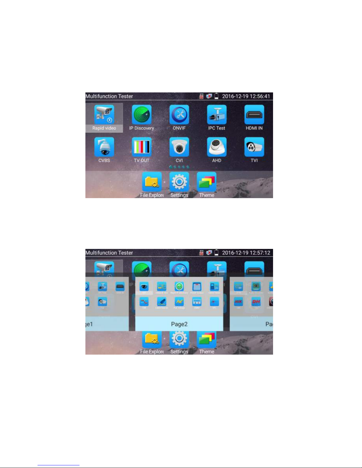
Page.17.
In normal mode, press icon several seconds, go screen management status. Change icons sequence and
move it to common tools bar.
You can move the icon to any pages,self-define the number of icons in any page. Make interface sample
and individuality.
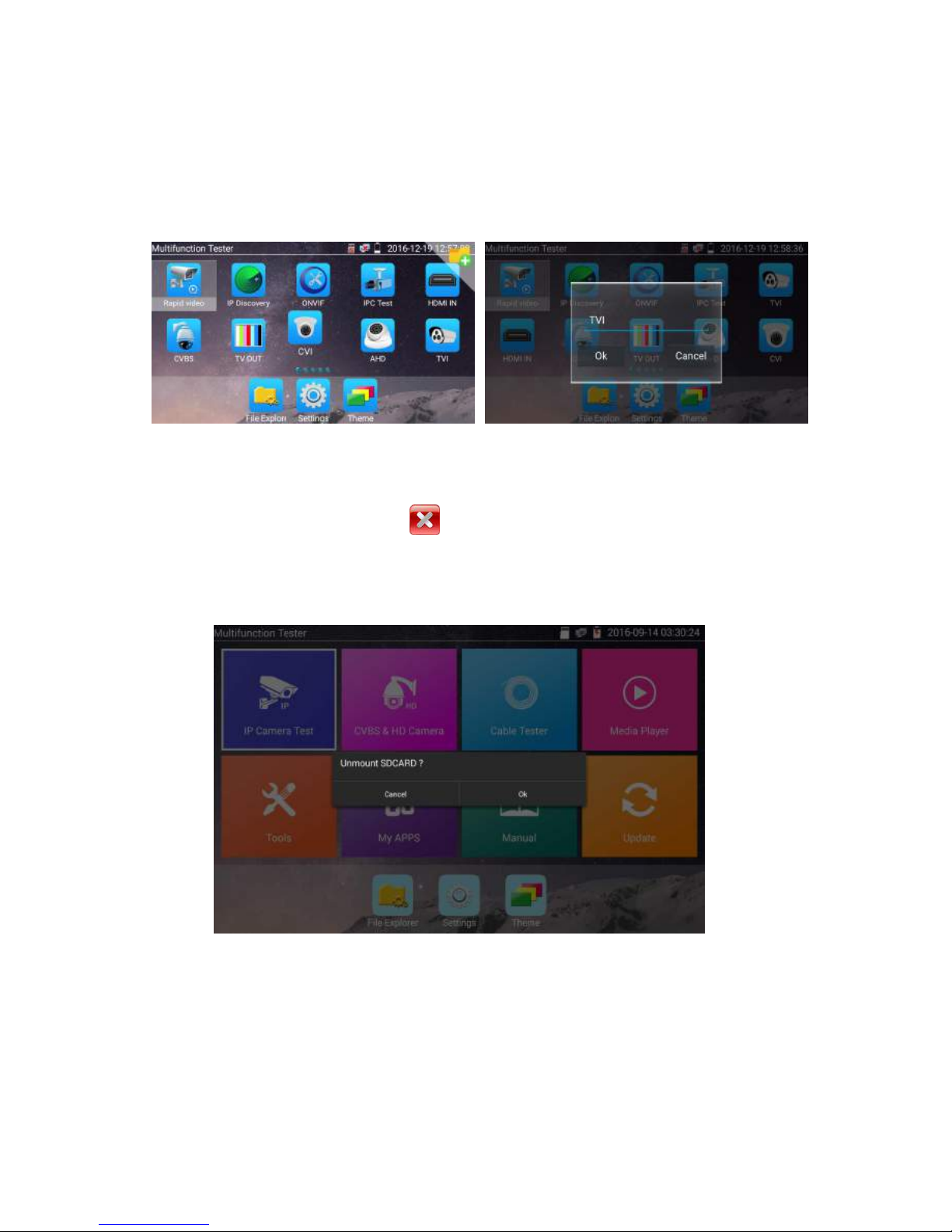
Page.18.
Create New Folder: Drag the icon to the folder in top right corner, enter the folder name. Icon will be
auto placed in the new named folder.
Press the folder several seconds, to change the folder name, you can move the icon out of folder, the
folder will be auto deleted until move out all icons.
Select Icons to enter, if quit, please click
Click SD card, install or remove SD card.
Page.19.
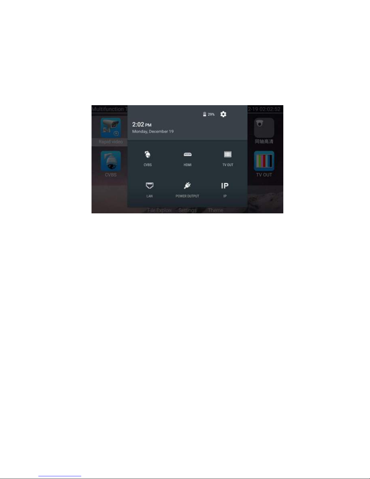
3.3.2 Drop-down Menu
Press and slide at right top right corner twice to open shortcut menu. The shortcut menu includes POE
power output, IP settings, Wi-Fi, HDMI IN, CVBS, Video OUT, LAN, Brightness, settings etc.
HDMI: Click HDMI IN to enter,In HDMI IN mode, it can converter test from analog to digital
with dual test window IP & HDMIN or Analog & HDMI in.
CVBS: Click icon “CVBS “to enter, you can test IP and analog camera at the same time.
TV OUT: Click Video OUT to enter floating window, connecting the BNC cable to tester and
appears analog video monitor interface, it can test circuit and BNC cable whether normal.
LAN: Display network port or WIFI connection real-time upload and download speeds and
other network parameters.
Brightness: Set brightness.
Settings: Enter settings interface.
IP: Enter IP Settings interface.
POE power output: Turn on or off the tester “PoE power “app.
WLAN: Turn on WLAN net and displays current WLAN status.
Page.20.
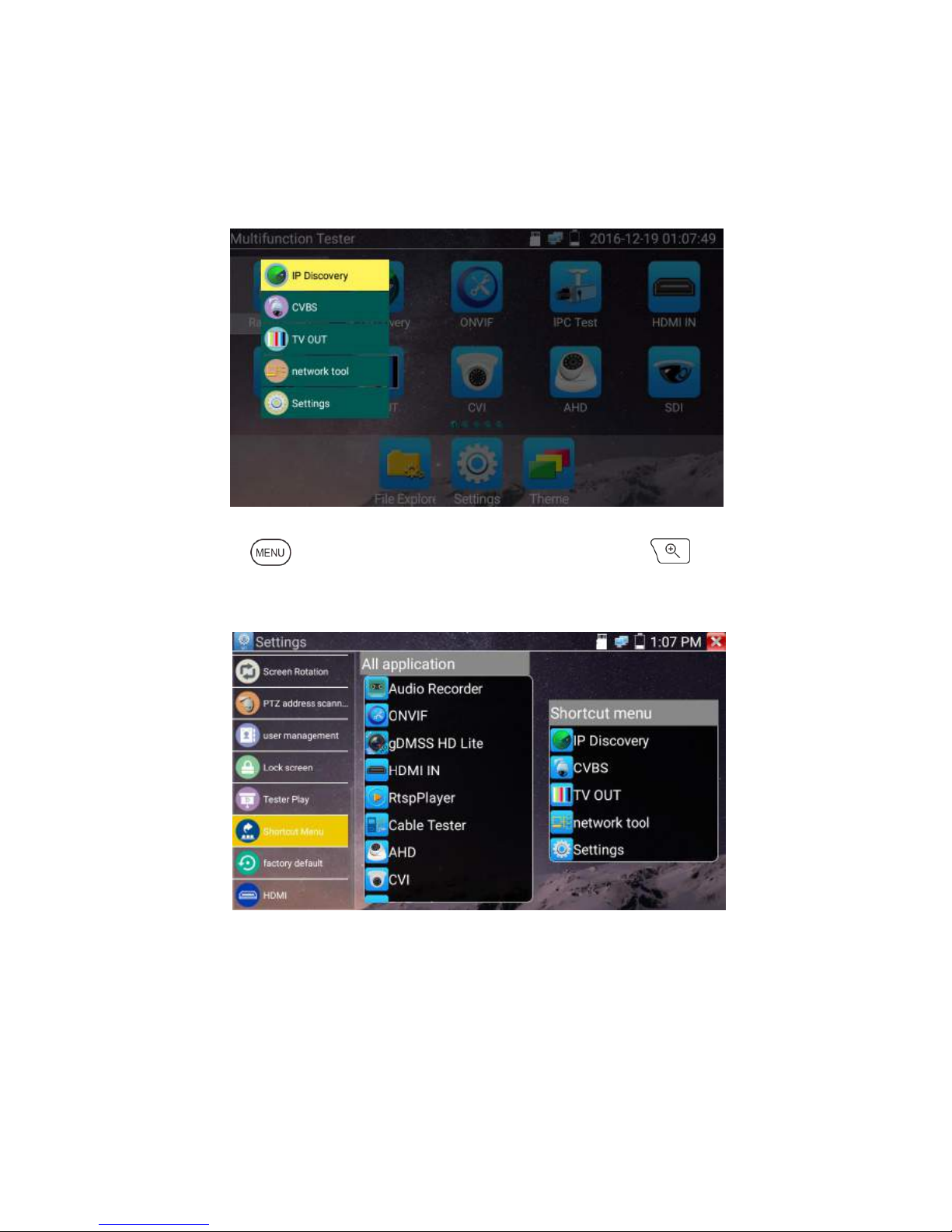
3.3.3 Short cut-menu
You can call shortcut –menu by press tester’s “menu” key, you can self- define shortcut -menu
Press the key“ ”, you can turn on it and switch functions, then press to enter app, tap
other area on the screen, to exit the menu
Short cut-menu setting, you can long press any app in the all applications list ,it will auto move to
shortcut menu . If delete any app in the short cut – menu ,please select a app and press several
seconds ,it will be deleted.
Page.21.
3.3.4 Screen capture
long press the key “enter”, can capture screen interface and save it in any time.
You can go file management to view “file management –sdcard- Pictures—Screenshots
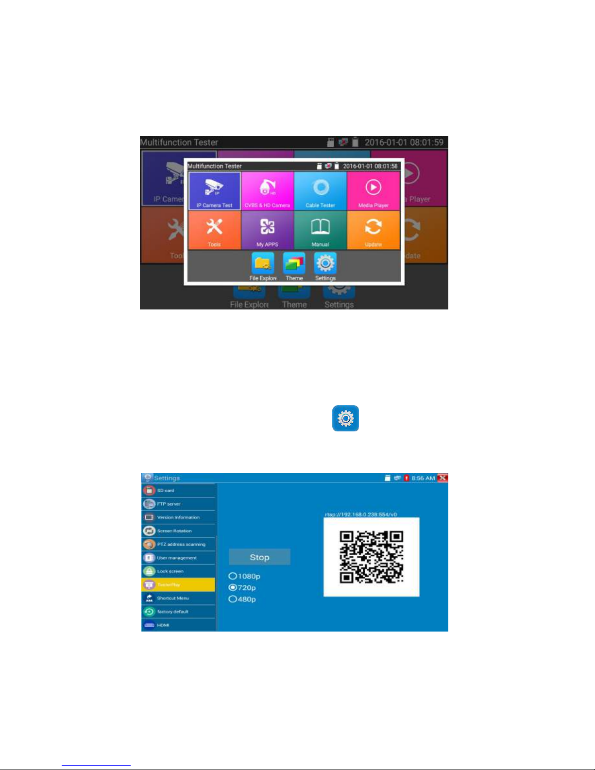
3.3.5 TesterPlay
Mobile screen projection (Only for android version)
The meter creates WIFI hotspot, connect mobile phone to the tester’s WIFI hotspot, or the tester and
mobile phone connect to the same Wi-fi network. Tap icon “ ”, then select “TesterPlay” app to
enter, click “Start” button to generates two-dimensional code, Please use mobile phone scan it, then
download and install the client software, you can view the screen real-time projection.
Page.22.
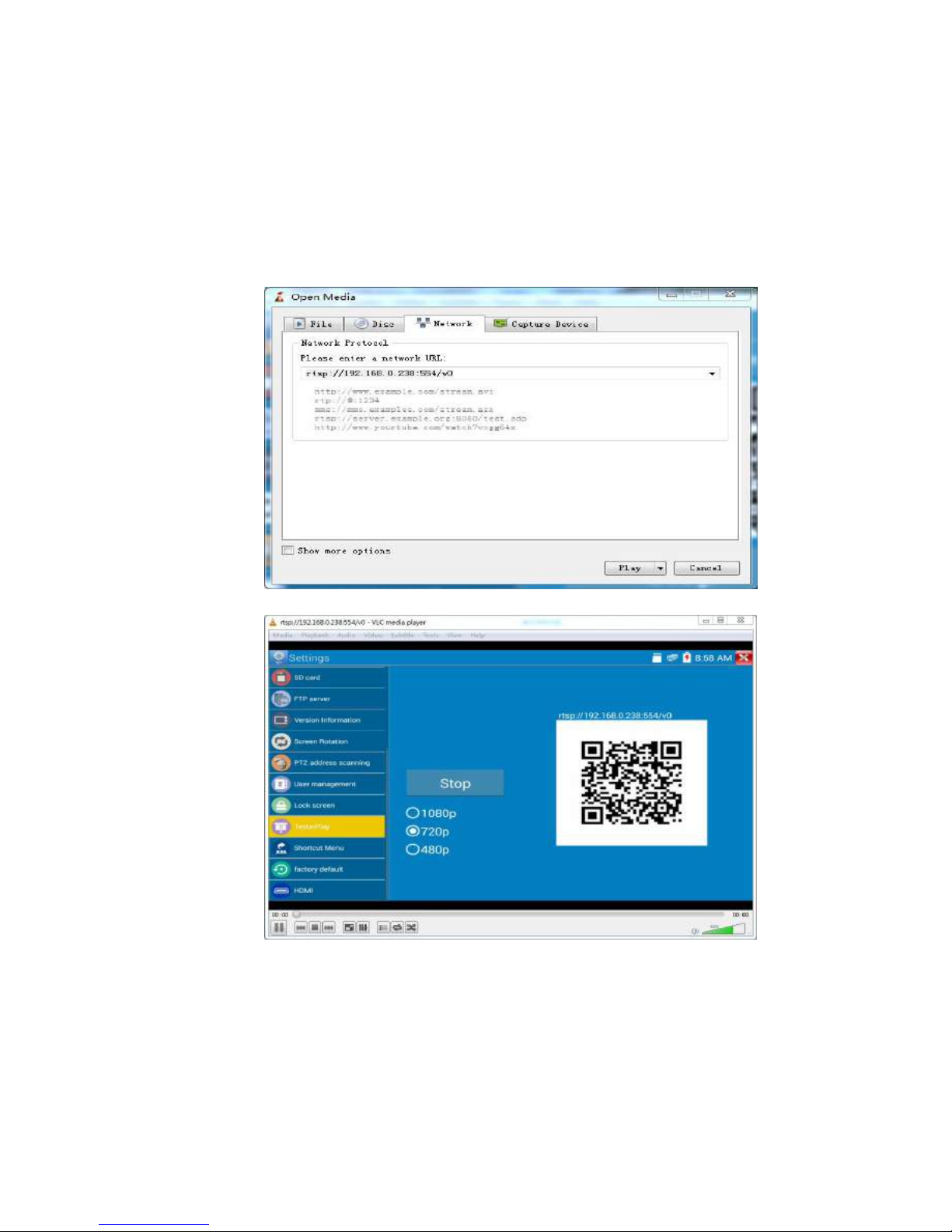
PC screen projection:
Install VLC player in the PC, turn on the VLC player "Media - Open Network Streaming", and
input the RTSP address of on the top instrument two-dimensional code, click "play" to view the
screen real-time projection.
Page.23.
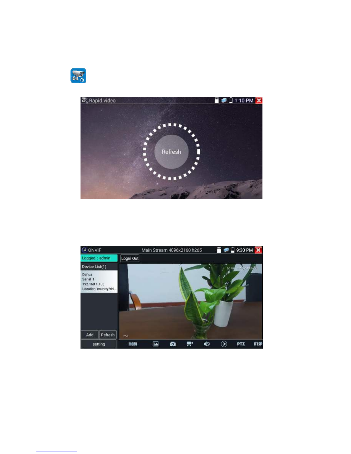
3.3.6 Rapid
video
Press enter function, One key to detect all network cameras and auto play the images.
Auto log in and display camera image. Detailed operation refer to ONVIF function
Page.24.
After exit ONVIF app, Click Refresh to search ip address.
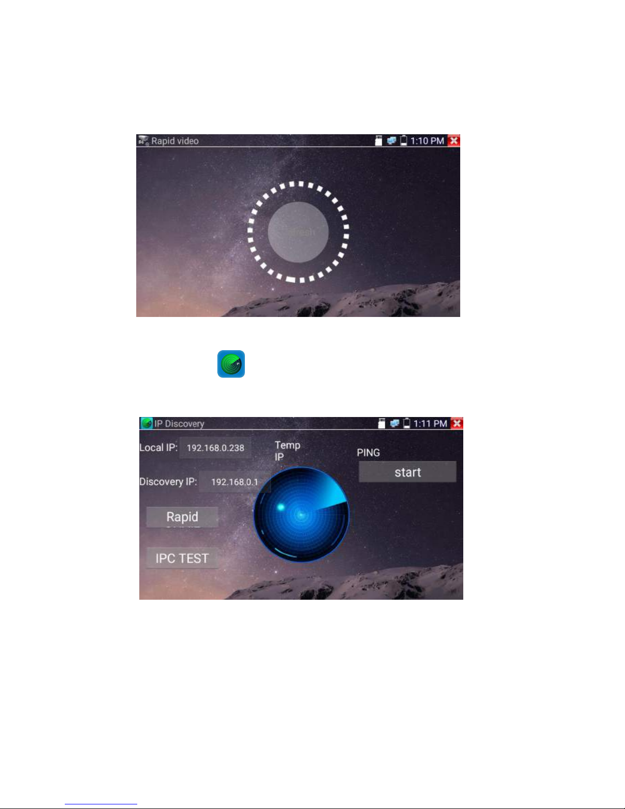
3.3.7 IP discovery
Press IP discovery ,tester auto-scan the whole network segment IP, as well as
auto-modify the tester‘s IP to the same network segment with the scanned camera's IP.
Local IP:Tester’s IP address, Tester can auto-modify the tester‘s IP to the same network segment with
the scanned camera's IP
Page.25.
Discovery IP:Connected tester equipment’s IP address. If the camera connected to the tester directly,
tester will display the camera’s IP address, if tester connects to Local Area Network, it displays the
current IP address.
Temp IIP:After searching IP address, the modified tester’s IP address will not be saved, if you do not
select “Temp IP,” the modified tester’s IP address will auto-save after searching.
Start:PING function, Click "Start", can PING camera’s IP
Rapid ONVIF:Rapid ONVIF Quick link
IPC TEST: IPC TEST Quick link
Applicability:Using IP discovery app ,you don’t need to know the first two digits of camera’s IP
address , it can auto-scan the whole network segment IP, and auto-modify tester’s IP address , greatly
improved engineering efficiency .
3.3.8 Rapid ONVIF test
Rapid ONVIF can display 4K H.265/H.264 camera image by tester mainstream, one key to activate
Hikvision camera
Press enter ONVIF function, the meter auto scan all ONVIF cameras in different network
segments. It lists cameras name and IP address on the Left of screen. Tester can auto login camera and
display camera image. Factory default use admin password to auto login, if you modified the password,
then default use the modified password to login

Page.26.
If you select ONVIF Rapid mode, the meter automatically scan different network segments for ONVIF
cameras. It lists the camera name and IP address on the Device List. Tester can auto login camera and
display camera image.
Click the button “Refresh”, tester will scan the ONVIF camera again. Click the newly displayed ONVIF
camera on the “Device List“. The tester will show the IP camera’s relative information and settings.
Activate HIKVISION Camera: When connected unactivated HIKVISION Camera, tester can auto
recognized ,And prompt "The camera is not active, you need to activate it", click "OK" to start activate .

Page.27.
Enter a new password for the camera
When comes out “activate success” prompt, click login to display camera image.
Pop-up settings menu when click the “ONVIF setting ”icon in the upper left corner

Page.28.
Across network segments scan: After open this function , enter “Setting”-“IP Settings”-“Advanced”to
add other network segments IP, Rapid ONVIF function can across network segments to scan camera’s
IP.
Auto Login : After open this function, tester can auto login camera and display camera image (The
login password is the same with last time, the first time using password is the default password
"admin")
Video transmission protocol: UTP and TCP protocol
Open password cracker : Cracks password of cameras
View manual : Open Manual
Restore Defaults: Revert “Rapid ONVIF” to default settings
Confirm : Save the modified parameters
Click “MENU”icon to open camera setting .

Page.29.
While in the “Live video” menu, click “Video Menu” at the top right of the image to access the
following tools: Snapshot, Record, Photo, Playback, PTZ and Settings
ONVIF PTZ control: Tap the image in the direction you want the PTZ camera to move. Tap the left
side of the image to move left, right to go right, up to go up and down to go down. Compatible IP PTZ
cameras will rotate accordingly. PTZ rotation direction is displayed on top left corner of the image.

Page.30.
IP camera video settings: Click “Video Set” to enter the IP camera’s encoder and resolution settings.
Make the desired changes and click “OK “to save.
Image setting: Click “Imaging Set” to adjust image brightness, saturation, contrast, sharpness and
backlight compensation mode.

Page.31.
Profiles:Click “profiles",can view video streaming current configuration files, as well as switch
between Major stream and minor stream .
Preview pictures:Quickly preview and zoom in or out pictures, automatically and manual refresh

Page.32.
Identification: click “Identification” to view information of the camera
Time set: click “Time set”, Select " Manual set" to set up the time of camera
Maintenance: For camera software reset or restore to factory settings.

Page.33.
User Set: Modify camera user name ,password etc parameters
Network setting:Click “Network Set “to change the IP address. Some cameras cannot support change
IP address, so there is no change after saving.

Page.34.
Zoom in image :press the key to enter the zoom mode. Press it again to exit zoom
mode.When the image is enlarged tap left, right, up or down on the image to move the whole image on
the screen
When the image is enlarged, if not operate on touch screen, it can operate by the keyboard ,press the
key to zoon in , press the key to zoom out ,press upward and downward
key to move image.
If it is network video input to the tester, as the tester supports resolution up to 1080p, the input image
will be very clear after it is enlarged. This is greatly helpful for the installers to ensure the IP camera’s
video coverage and decide the IP camera’s install site.
Image can only be enlarged on SD mode (The icon “ONVIF”is SD mode.)
Select relative function on the bottom Toolbar to operate, “Snapshot“ , “Record”, “Photos ”,
“Video playback”, “Storage set”, “PTZ control” etc.

Page.35.
Snapshot:Click bottom “snapshot” to screenshot the image and store it to SD card.
if select manual storage, appears dialog box “Input Name” , user-defined the files name(by Chinese
character, English letter ,or digit ) to save in SD card, if select “Auto- storage”,the tester auto stores the
files after snapshot.
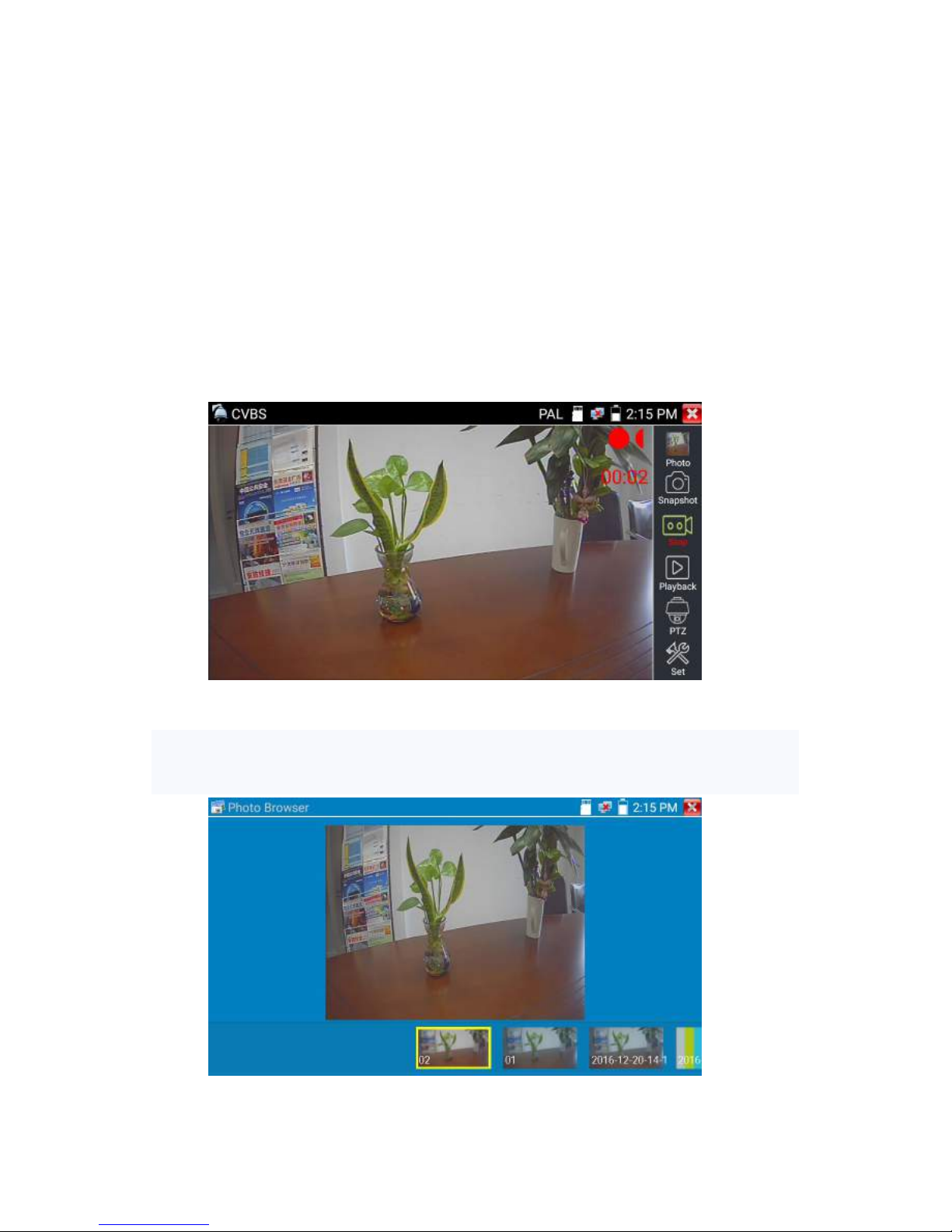
Record:When you click bottom the “Record” icon, video starts recording. A red recording icon
appears on the screen and begins to flash and a timer appears indicating the time elapsed for the video.
Click on the “Stop” icon to stop recording and save the video file to the SD card.
Playback:Click the “Playback” icon to view saved videos. Double click the video you want to play.
Click to return to the last menu

Page.36.
To rename or delete a photo, click and hold on the file until this screen appears:
Video files can play in the Video player on the main menu.
PTZ
Set preset position :Move the camera to preset position, enter the preset number on the Bottom right
corner to complete position preset.
Call the preset position : Select the preset number on the left, click "Call"to call preset

Page.37.
PTZ Speed set : Horizontal and Vertical Speed set
RTSP: Get RTSP address of the current camera
Doc: Auto generate test reports document of camera, click "Create document”. Click Preview to view
the report document

Page.38.
Enter the camera test information, click "Create Document" to complete the report.
click doc menu again, you can preview the report document.
Icons description: the description of function icons on the bottom toolbar
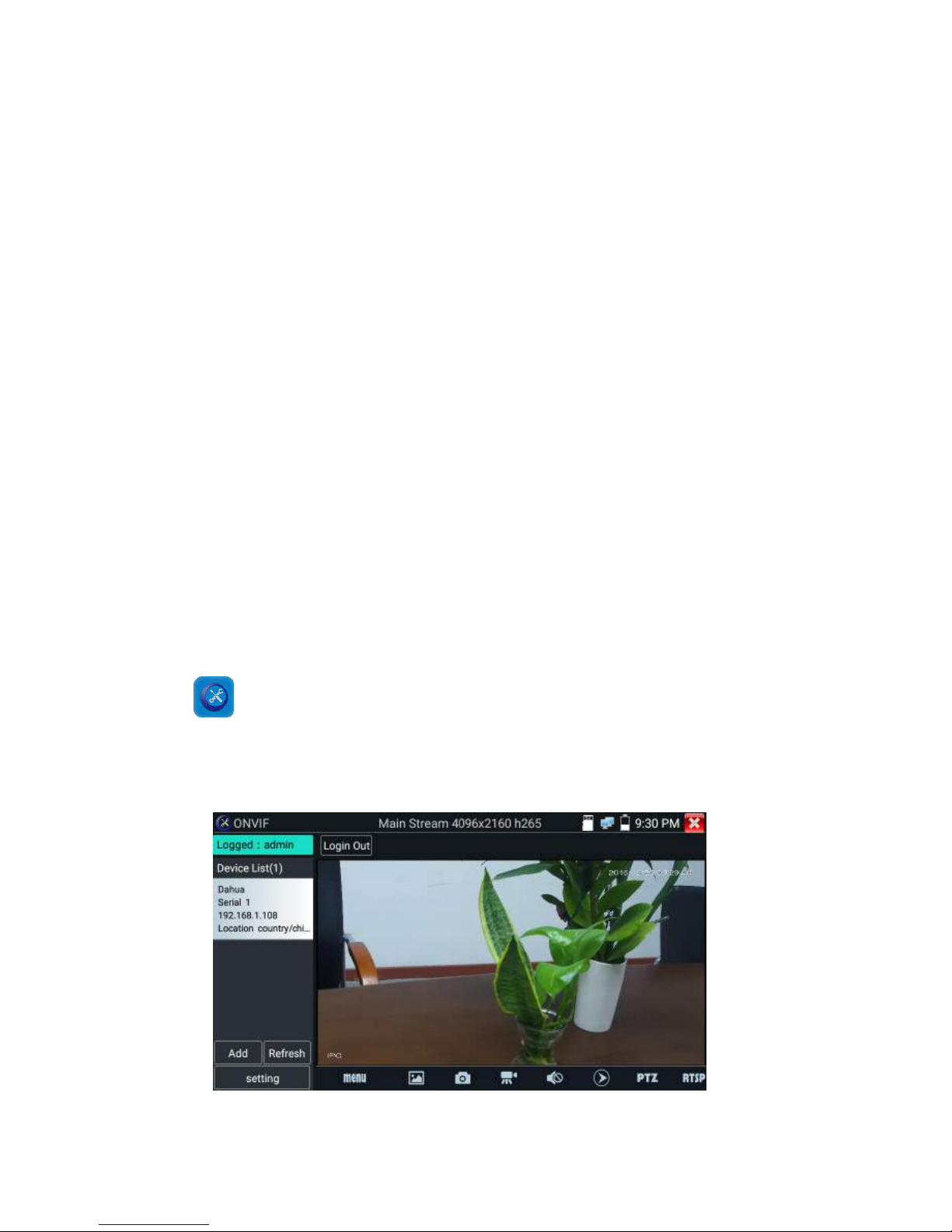
3.3.9 IP camera test
Display image from the 4K H.265 camera by mainstream
Click icon to enter IP camera test
Note: Currently, the IPC Test App only supports some brands’ specific IP cameras,these include
specific models made by ACTI, AXIS, Dahua, Hikvision, Samsung, and many more. If the camera is

Page.39.
not fully integrated, please use the ONVIF or RTSP apps.
IPC test interface
Local IP: This is the tester’s IP address. Click “Edit“ to enter “IP setting“ and change the tester ‘s IP
address settings
IP camera type : Click on the IP Camera type to select the Manufacturer and model number of the
integrated IP camera
Manual:Click IP camera type, list Honeywell , Kodak,Tiandy, Aipu-waton, ACTi,WoshiDA IP camera
etc. If the brand has offered official original protocols, pls select camera type, input IP camera
address ,user name and password ,click” official” to enter the camera image display interface(Currently,
only support DAHUA official protocols )

Page.40.
Stream code: When test camera via RTSP, you can select mainstream or sub stream to test (if camera’s
RTSP have not been start or without, it will tip “auto match fail, please witch to manually selecting
IP Camera's IP: Enter the IP camera’s IP address manually or click “Search” to auto-scan for the IP
camera’s IP address. It is better to directly connect the IP camera to the tester so the search results will
only display the camera’s IP address. If the tester is connected to a PoE switch, it will find and display
several IP address
IPC User Name: Enter IP camera’s user name
IPC Password: Enter IP camera’s login password
IPC Port :: When you select the IP camera type, it will default the camera’s port number and doesn’t
need to be changed.
After all settings are completed, click “Enter” to view the live video

Page.41.
If IP address setting has error or IP camera is not connected.. The tester prompts “Network Error”
Click to quit from image display and return to IP camera test interface.
Once you are viewing video on the IPC Test app, you will see the “Video Menu” icon on the top
right. This button will give you access to Snapshot, Record, Photo, Playback, PTZ, and Set. Please refer
to the ONVIF section to use these functions.
3.3.10 HDMI IN ( *Optional )
HDMI in HD signal test, Tap icon “ ”to enter
When tester receives HDMI in image, the top tool bar shows the resolution of this image. You can
select “resolution ”to set resolution in the setting menu .Tap screen by twice, full image display.
Support resolution below
720×480p /720×576p /1280×720p /1920×1080p /1024×768p/1280×1024p /1280×900p /1440×900p
(1) Snapshot
Click the icon “Snapshot “, when the video in, to take a picture and save the current video frame in the
SD card as JPEG file.
If the unit is set to the manual mode an “Input Name” pop up box will appear and you can enter a title

Page.42.
for the snapshot. If the unit is set up to automatically set file names, this box will not pop up.
(2) Video record
When you click the “Record” icon, video starts recording. A red recording icon appears on the screen
and begins to flash and a timer appears indicating the time elapsed for the video. Click on the “Record”
icon again to stop recording and save the video file to the SD card.
if select manual storage, before recording begins ,appears dialog box “Input Name” ,user-defined the
files name(by Chinese character, English letter ,or digit) to store in SD card , tester will hereby store the
files in SD card after recording . if select “Auto-storage ,tester will auto store the files in SD card after
recording .

Page.43.
(3)Photo
Click the icon “photo” to enter, click the selected thumbnail photo to display it on the screen.
Double-tap the image you want to view to make it full screen. Double-click again the photo to return.
To rename or delete an image, click and hold on the file until this screen below appears
Click to close and return to PTZ controller.

Page.44.
(4) Recorded video playback
Click the “Playback” icon to view your recorded videos. Tap on the video file image you want to watch.
To rename or delete a video, click and hold on the file until this screen appears:
Video files also can play in the main menu “Video Player".
Page.45.
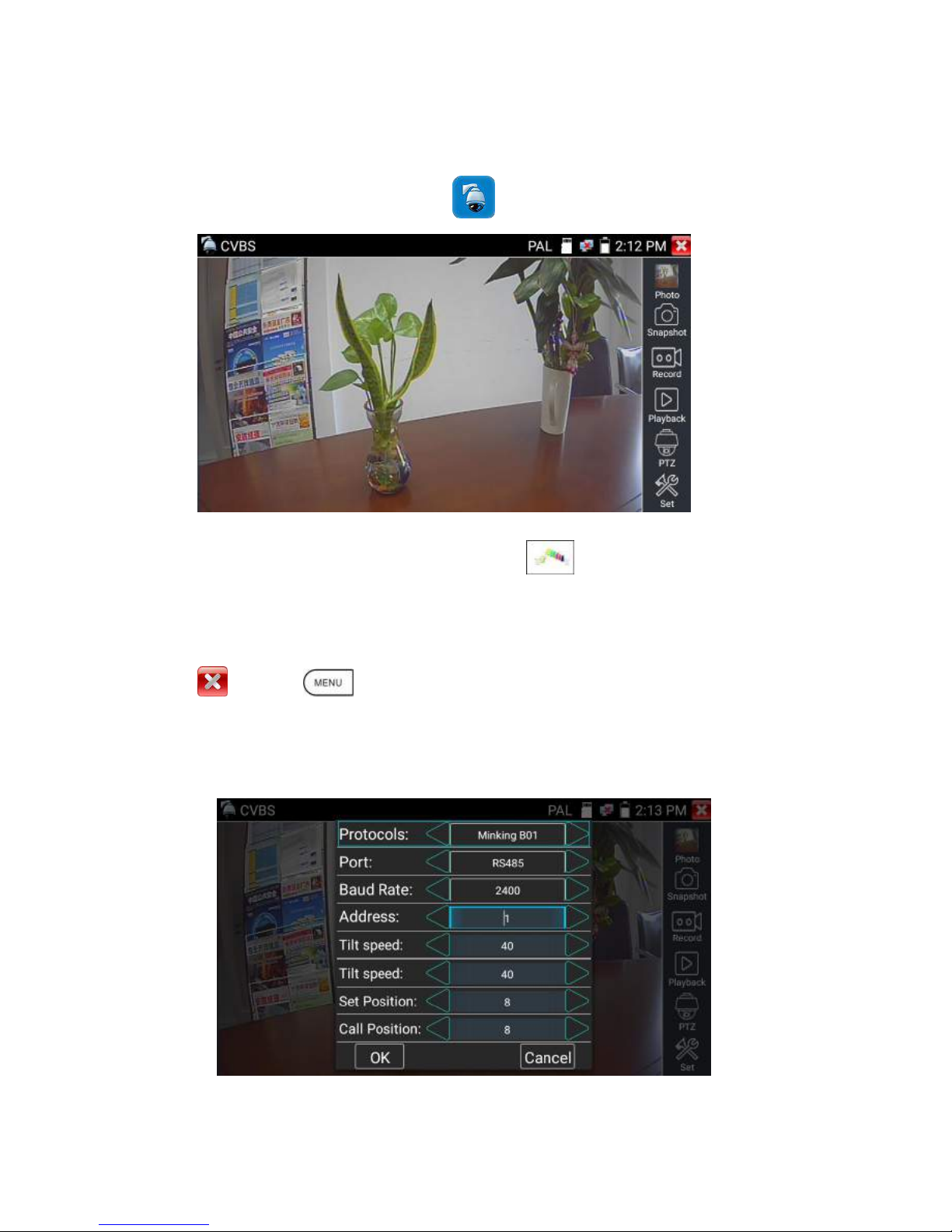
3.3.11 Video monitor test
Analog camera test and PTZ control, click icon to enter
Display the input video image, click the top menu bar icon to enter video level meter,
(PEAK level, SYNC level, COLOR BURST measurement)
Select relative function on the right side Toolbar to operate , functions including “Photos”, “Snapshot” ,
“Record” , “Playback” , “PTZ” , “Set” ,
Click , or press to quit.
Click the screen twice quickly, can be full zoom in on the touch screen.
(1) PTZ controller parameter setting
Select and click icon “PTZ”, to enter PTZ setting:

Page.46.
A. Protocol
Use the up and down arrow keys to move the yellow cursor to the “protocol ”, set corresponding
Protocol and support more than thirty PTZ protocols. Such as
Pelco-D,Samsung,Yaan,LiLin,CSR600,Panasonic,Sony-EVI etc.
B. Port
Click and move, to “port” Select the communication port for the PTZ camera controlling (RS485)
C. Baud
Move the yellow cursor to “Baud”, Select the baud rate according to baud rate of the PTZ
camera.(150/300/600/1200/2400/4800/9600/19200/57600/115200)
D. Address
Set the ID according the ID of PTZ camera (0~254), the setting address data must be consistent the
speed dome address.
E. Pan speed: Set the pan speed of PTZ camera (0~63)
F. Tilt speed: Set the tilt speed of PTZ camera (0~63)
G. Set preset position (Set PS)
Click and select “Set PS”, set and save preset position number(1~128),
H. Call the preset position (Go ps)
Click and select “Set PS”, set and save preset position number (1~128), click “sure” to save,
Call some special preset number, can call the dome camera menu
Check and set the protocols, address, interface and baud, all must be consistent with the dome camera,
then the IPC tester can test .After setting the parameter, the tester can control the PTZ and lens
To control PTZ by screen touch:
Tap left, right, upward and downward on the touch screen to control the PTZ rotation direction. By two
fingers move outward and inward on the touch screen to zoom in and out the PTZ.

Page.47.
PTZ Control:
Press the key control the PTZ direction of rotation
Press the key or , to switch on or turn off the aperture.
Press the key or , adjust the focus manually
Press the key or , manually adjust the zoom
2) Video and storage setting
Click icon “set”,to enter and set analog video image brightness , contrast, color saturation, as well as the
file storage way after snapshot and recording, support auto-storage and manual storage.
When select manual storage, user can name and store the files.
(3) 4 x zoom image display and Video out
When image input, press to enter “zoom”, press it again to quit.
Using the touch screen to control PTZ camera movement:
Tap left, right, upward or downward on the video image to move the PTZ camera in a desired direction.
Stretch two fingers outward or inward on the touch screen to zoom the image in or out.

Page.48.
If not use touch screen to operate, press the key to zoom out , press the key to
zoom in, press upward and downward key to move the image
For analog video input, as the resolution is 720*480, it is normal that the zoom in image is not
clear. But for network digital video input, as it supports resolution up to 960*540, the zoom in image
is still very clear. This is very helpful for IP camera installation.
(4) Snapshot
Click the icon “Snapshot “, when the video in, to take a picture and save the current video frame in the
SD card as JPEG file.
If the unit is set to the manual mode an “Input Name” pop up box will appear and you can enter a title
for the snapshot. If the unit is set up to automatically set file names, this box will not pop up.
Page.49.
(5) Video record
When you click the “Record” icon, video starts recording. A red recording icon appears on the screen
and begins to flash and a timer appears indicating the time elapsed for the video. Click on the “Record”
icon again to stop recording and save the video file to the SD card.
if select manual storage, before recording begins ,appears dialog box “Input Name” ,user-defined the
files name(by Chinese character, English letter ,or digit) to store in SD card , tester will hereby store the
files in SD card after recording . if select “Auto-storage ,tester will auto store the files in SD card after
recording .
(6)Photo
Click the icon “photo” to enter, click the selected thumbnail photo to display it on the screen.
Double-tap the image you want to view to make it full screen. Double-click again the photo to return.

Page.50.
To rename or delete an image, click and hold on the file until this screen below appears.
(7) Recorded video playback
Click the “Playback” icon to view your recorded videos. Tap on the video file image you want to watch.
To rename or delete a video, click and hold on the file until this screen appears:

Page.51.
Video files also can play in the main menu “Video Player".
(8) Video level meter
Click the icon to enter, the IP camera tester has adopted hardware high-speed sampling and
processing technology, can perform both NTSC and PAL video amplitude signal measurements for
PEAK to PEAK, SYNC levels and COLOR BURST chroma level. When an analog signal is fed into
the meter, the tester displays the measurements on the bottom left corner of the screen
While in PAL format, the unit will be mV, While in NTSC format, it will be IRE.

Page.52.
Video signal PEAK to PEAK level:
For NTSC format, the video signal level is 140±15IRE
For PAL format, the video signal level is 1000±200mV
If the level is too low, it will cause the image to lose quality and limit the distance it will travel over
cable. If the level is too high, it will distort the image.
SYNC level: Tests the amplitude of the video sync pulse to verify if the video level is correct.
For NTSC format, the SYNC level is 40 ± 5IRE
For PAL format, the SYNC level is 300 ± 35mV
If the level is too low, it will cause the image to not frame out properly. If the level is too high, it will
lead to a poor quality image.
COLOR BURST level: Testing the color burst level will determine if the burst signal is sufficient to
trigger the displays color producing circuit. Burst will diminish in amplitude over longer cable runs and
can get fall below the threshold for the video display to show a color image.
For NTSC format, the Chroma standard level is 40 IRE
For PAL format, the Chroma standard level is 280mV
If the Chroma level is too low, the color will not be as deep, and some details of the image will become
lighter. If the Chroma level is too high, there will be distortions on the image. If the coaxial cable is too
long, it will reduce the chroma level.
Image loop test:Test video optical transmitter and receiver and video cable, connect one end to the
tester “VIDEO OUT” port ,and the other end connected to “VIDEO IN” port, the signal send via
“VIDEO OUT” port ,and received via “VIDEO IN” port , If the testing is ok, the tester displays several
gradually dwindling photos on the desktop.
NTSC
Video signal level
140±15IRE
Chroma level( COLOR BURST)
40±5IRE
SYNC signal level
40±5IRE
PAL
Video signal level
1000±200mV
Chroma level( COLOR BURST)
300±35mV
SYNC signal level
300±35mV

Page.53.
3.3.12 Color-bar generator (TV OUT)
Click to enter, the tester sends the color bars from the “Video out” port ,Click the icon “PAL”,
select “PAL/NTSC” output formats.
Click the selected color-bars, testing image or single bar ( red, green, blue, white or black). Double click
to full display on the screen and output, click to return main menu.
Application

Page.54.
BNC loop test: Tester can send and receive color bar generator through the tester’s “video out and
video in” port, it is for testing transmission channels, such as video Optical, video cables etc. The tester
“VIDEO OUT” port to connect optical terminal’s sending port, and “VIDEO IN” Port to optical
terminal’ s connect its receiving port.
A. When maintaining the dome camera, the tester sends out the color bar by its BNC output to the
monitor at the monitoring center. If the monitor receive the color bar, it means the video transmit
channel works normally. Meanwhile on the basis of the received color bar, the monitoring center can
judge if transmission has loss or interference.
B. The tester sends out the pure color bar (such as white and black color), to test the monitor whether
has bright or black dots
C. The tester sends out video signal image to test if the image received by the monitor has excursion.
3.3.13 SDI Camera Test ( *Optional )
SDI camera test, Dome camera test and PTZ control, click icon to enter.
When tester receives SDI camera image, it will display the image data.
Double-taps on the screen to make the image displayed full screen.

Page.55.
The tester supports resolution as follows:
1280x720P 25Hz
1280x720P 30Hz
1280x720P 50Hz
1280x720P 60Hz
1920x1080P 25Hz
1920x1080P 30Hz
1920x1080I 50Hz
1920x1080I 60Hz
IPC tester’s HDMI output port can be use as SDI to HDMI converter, output HD SDI image to HD TV
monitor.
Select relative function on the right side Toolbar to operate, “Snapshot“ , “Record”, “Photos ”,
“Video playback”, “PTZ control”, “Video Brightness and Storage set”, the operation is the same to
the video monitor function, please refer to the relevant instructions “3.3.1” in the manual.
Click , or press to quit.
3.3.14 CVI camera test ( *Optional )
HD CVI camera, CVI dome camera test and PTZ control, click icon to enter

Page.56.
When HD CVI signal input, the tester will display the image resolution on the top bar. Double-taps on
the screen to make the image displayed full screen.
The tester supports resolution as follows
1280x720P 25FPS / 1280x720P 30FPS / 1280x720P 50FPS / 1280x720P 60FPS
1920x1080P 25FPS / 1920x1080P 30FPS
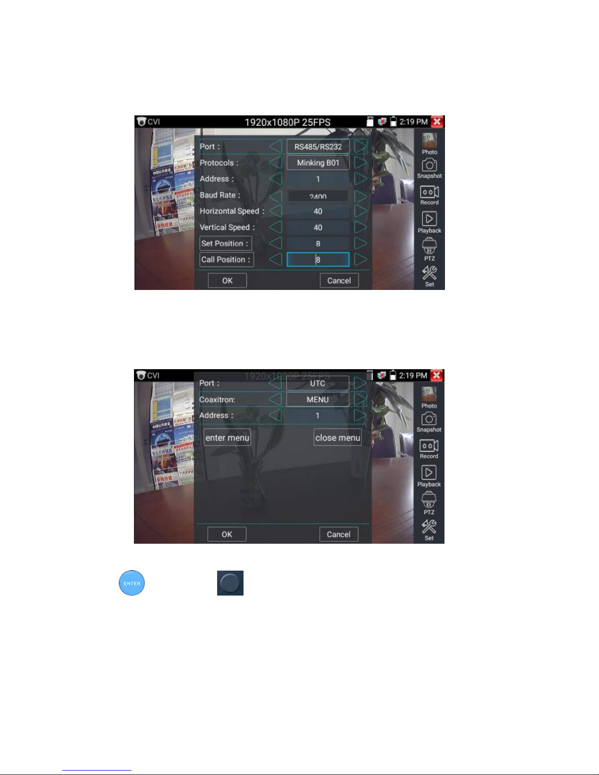
(1)PTZ control
1.1 Coaxial PTZ control
Click the icon“PTZ”on the right toolbar to do the corresponding setting.
“Port”: select coaxial control

Page.57.
Enter PTZ address to perform parameters setting
Operation instructions, please refer to “3.3.1 PTZ (1) Video monitor test”
The PTZ address in the tester must be consistent with the dome camera or decoder, then the IPC
tester can test .After setting the parameter, the tester can control the PTZ and lens.
To control PTZ by screen touch:
Tap left, right, upward and downward on the touch screen to control the PTZ rotation direction, PTZ
cameras will rotate accordingly. By two fingers move outward and inward on the touch screen to zoom
in and out the PTZ.

Page.58.
PTZ Control:
Press the key control the PTZ direction of rotation
Press the key or , to switch on or turn off the aperture.
Press the key or , adjust the focus manually
Press the key or , manually adjust the zoom
Set preset position:
Move the PTZ camera to the preset position, the Tap it and input preset position number. Tap “Set
position” to complete set preset position.
Call preset position
Tap the preset position:
Tap the preset position area, input preset position number. Tap “call position” to complete call preset
position.
Page.59.
1.2 RS485 control
Operation instructions, please refer to “3.3.1 PTZ (1) PTZ control parameters setting”
(2)Coaxial camera menu setting
Tap icon “UTC””, select “menu setting” to enter the dome camera menu
Input calling dome camera menu address code, after finishing the parameter settings, you can press the
key or click the icon to call the dome camera menu.

Page.60.
Press arrow keys to set
(3) Snapshot, record, photo viewer and video play back, please refer to “3.3.1 PTZ (1) Video monitor
test”.Tap “close menu” or press the key “ ”to close camera menu

Page.61.
(4) Save setting
Click icon “Set” on the right toolbar to enter storage setting.
Support auto-storage and manual storage.
When select manual storage, user can name and store the files.
3.3.15 TVI camera test ( *Optional )
HD TVI camera, TVI dome camera test and PTZ control, Click icon to enter
When HD TVI signal input, the tester will display the image resolution on the top bar. Double-taps on
the screen to make the image displayed full screen.
The tester supports resolution as follows:

Page.62.
1280x720P 25FPS / 1280x720P30FPS / 1280x720P 50FPS / 1280x720P 60FPS
1920x1080P 25FPS / 1920x1080P 30FPS / 1920x1080P 50FPS / 1920x1080P 60FPS
Coaxial camera menu settings
Tap icon “UTC”, select “menu setting” to enter the dome camera menu
Input calling dome camera menu address code, after finishing the parameter settings, you can press the
key or click the icon to call the dome camera menu

Page.63.
More operation instructions (such as PTZ control, coaxial camera menu setting ,snapshot, recording and
playback etc), please refer to“3.3.6 CVI camera test”
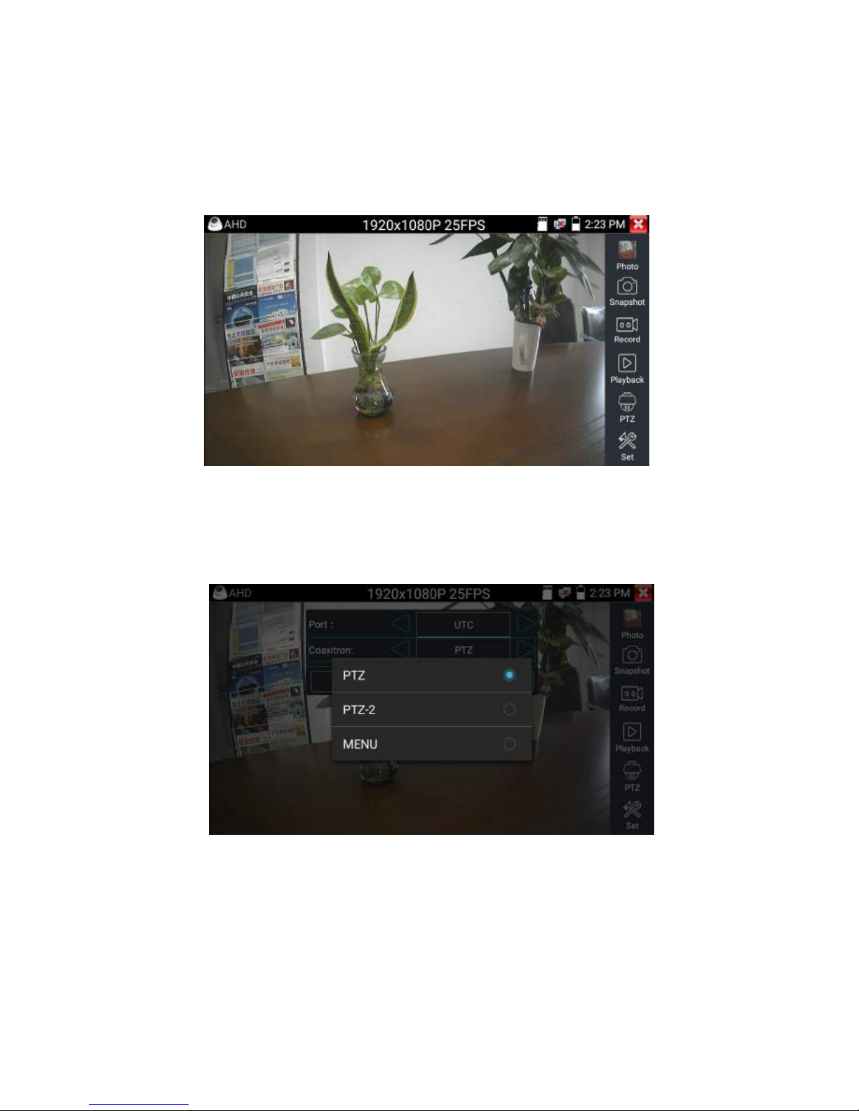
3.3.16 AHD camera test ( *Optional )
AHD camera, AHD dome camera test and PTZ control, Click icon to enter
When AHD signal input, the tester will display the image resolution on the top bar. Double-taps on the
screen to make the image displayed full screen.
Page.64.
The tester supports resolution as follows:
1280x720P 25FPS / 1280x720P 30FPS / 1920x1080P 25FPS / 1920x1080P 30FPS
(1) Coaxial PTZ control
UTC control : select “PTZ control or PTZ control-2”(AHD camera has two different order ,if select
“PTZ” cannot control , pls go “PTZ-2” )
If to coaxial PTZ control the AHD camera, no parameters setting is needed.
More operation instructions please refer to “3.3.6 CVI camera test”
Page.65.
3.3.17 Network tool
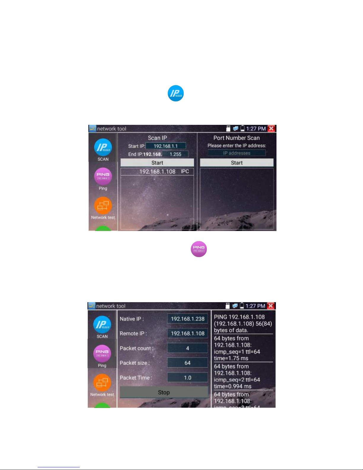
(1)
IP address scan
Connect the cable to the LAN port, click icon to enter, Set your IP address search range by
changing the Start and End IP addresses. Click the “Start” button to scan the IP address range. You can
also input an IP address in the Port Number Scan to scan for open ports.
(2)
PING Test
Connect a network cable to the LAN port and click the icon to open the PING tool. You can set
your LOCAL (native) IP address, Remote IP address (e.g. IP camera), Packet count, Packet Size, Packet
time and Timeout. Press “Start” to start pinging. If the IP camera or network device is not configured
properly or not plugged in, it will say “Destination host unreachable,” or have 100% packet loss. If the
tester connects to the device, the send and receive packets will have a 0% packet loss.

Page.66.
Application: PING testing is the most conventional network debugging tools. It is used for testing if
the connected IP camera or other network equipment’s Ethernet port is working normally and the IP
address is correct.
It’s normal that the first data packet will be lost when test start.
(3)
Network test (Ethernet bandwidth test)
Network test (Ethernet bandwidth test)
To use the Network tester, you will need two IP testers. One is used as a Server and the other as a Client.
Both devices must be on the same network segment in order to communicate. Click the icon to
open the Network Tester app.
a).Start the server: Click “Start Server” button to use the tester as a Server. It will display its IP
address at the top of the screen.

Page.67.
b). Start send packet test: Using the other IP tester, type in the Server's IP address at the top right
corner of the screen. This app is used to send packets for network speed testing. Click the “Start” button
to send the packets and start testing.
Network bandwidth testing can also be tested with a computer using compatible network bandwidth
testing software. Install network bandwidth testing software on a computer, as a test Client or Server, to
do the mutual testing with the tester. If use computer as the server, the computer IP address
is :192.168.0.39
Tester as Client, tester’s IP address is:192.168.0.238. The Server and the Client are at the same network
segment, but with different IP address. Input Server’s IP address 192.168.0.39 in the tester and click

Page.68.
“Start” to test network bandwidth.
Or use tester as a Server, computer as test Client(select Client, input tester’s IP address to test)
When use tester as Server, shows results:

Page.69.
(4)
Port Flashing
Connect a network cable to the meter’s “LAN” port, click the icon to open the Port Flashing
app. Click “Start”. The IP tester sends a unique signal to make the connected LAN port of the switch
flash.
If the tester and PoE switch are connected well, the LAN port of POE switch flash at special frequency,
If not, no any changes on the LAN port
Application:
The tester will send special signals to make the connected LAN port flicker at special frequency, which
will enable the installers to easily and quickly find the connected Ethernet cable. This function can
prevent mistakenly insertion or disconnection non-corresponding cable to artificially interrupt network
connection.

Page.70.
(5)
DHCP server
Click on the DHCP icon to open the DHCP server app. Select the “Start” check box at the top and make
any desired changes to the network settings. Click “Save” to start assigning dynamic IP addresses for
IP cameras and other networked devices. Click the “Refresh” button to check your Client list.
(6)
Trace route
It is used to determine path of the IP packet access target.
Note: Trace route testing results only for reference, for accurate test route tracking, Pls use professional
Ethernet tester.
Click to enter trace route
Input tracking IP address or domain name in the Remote Host IP. Set maximum hop count, normally
default is 30

Page.71.
Click “start” to trace the goal address
(7)
Link monitor
Click the icon to open the Link Monitor app. This app is used to see if an IP address is occupied
by other network devices. This will avoid new address conflicts
Click “Add” and enter the desired IP address. To test different network segments, click the “Settings”
icon on the main menu and go to IP Settings and make the desired changes. Once the desired IP
addresses are added to the Link Monitor list, click “Start”. If the IP address status shows a check mark
the IP address is occupied. If the IP address status shows an X the IP address is available. Click “Stop”
to stop the testing

Page.72.
Application:
Add an IP camera or other network device to the current network group, the new IP address must not be
occupied, otherwise it will result IP conflicts and stop the equipment normal working. Link monitor can
check if the new setting IP address is occupied.
3.3.18 Rapid IP Discovery
Connect the cable to tester’s LAN port. Press to enter Rapid IP Discovery app.
Click “Start “to search all IP address of connected equipments in whole network segment.
Click “Stop “to stop work.
3.3.19 PoE power / DC12V 2A and DC 5V 2A USB power output
When the tester is turned on, the DC12V and DC5V power output functions are automatically turned on.
If the IP tester is turned off, the 5VDC USB can still be used to power an external USB device.
To use the PoE Power Output function, click on the icon and change the switch “ON” or “OFF”.
The IP camera needs to be connected to the LAN port before you turn PoE Power on. If the IP camera
Supports PoE, the PoE power is delivered via pins 1, 2, 3, and 6 on the LAN port. The IP tester will
display “48V ON” at the top of the screen when the POE power is still on.

Page.73.
Note:
1. Don’t input power into the “DC12/2A OUTPUT” port.
2. Don’t output this DC12V/2A power to the DC12V/IN port of the IP camera tester to avoid destroy
3. The IPC tester power output is close to 2A, if the IP camera’s power is over 2V, the tester will auto
enter protection mode. Disconnect all the connections of the tester and then connect the tester with
power adaptor to resume the tester.
4. Before turning on the PoE power output, please make sure the IP camera supports PoE power.
Otherwise it may damage the IP camera.
5 Make sure you plug in your IP camera to the LAN port prior to turning on PoE power
6. Make sure the tester is full charged or more than 80% charged, otherwise the tester will shows
“low power”, “not able to supply power”.
3.3.20 Cable Test
Click icon to enter

Page.74.
Test LAN cable or telephone cable.
Connect LAN cable or telephone cable with the CCTV tester and cable tester. And then the
connecting status, cable type and the sequence of wires as well as the serial number of the cable tester
kit will be displayed.
The number of the cable tester is 255
If need several different number other types cable testers, should pay the additional cost.
Tap "cable test sketch map" ,pop up Straight-through cable and crossover cable skectch, It is for line
sequence reference ,when the crystal on the first pressure in the twisted-pair
3.3.21 RJ45 cable TDR test
Connect cable to tester’s LAN port, click icon “ ” to enter RJ45 cable TDR test app.

Page.75.
Single test: Test cable status, length and attenuation.
Repeat test: Continue to test cable status, length and attenuation.
Status: After link up, screen display “online”, if not link up or open circuit, screen display ”open
circuit”, if cable pair is short circuit, screen display “short circuit”
Length: The max test length is 180 meters, when cable is open circuit or short circuit, can test
the cable length, if screen display “online”, the testing result would be not accurate.
Cable quality test: Green is good quality cable, Yellow is Poor quality cable, Red is water
poured cable, the attenuation value will be displayed when cable over 10 meters
Advanced Test: Test cable pair status, length, attenuation, reflectivity, impedance, skew and
other parameter.
Attenuation reflectivity: After link up, if reflectivity value is 0, it is the best quality
communication
Impedance: After link up ,if the impedance value is 100 Ω,it is the best quality communication,
the range is generally in 85-135 Ω
Skew: After 1000M link up, when skew value is 0ns,it is the best quality communication, if over
50ns, will cause a Bit Error Rate in the transmission.
Connection diagram

Page.76.
Cable sequence diagram:
A straight- through and cross-over cable diagram, the cable sequence display for reference
Click “Help”, check the instruction of all parameters.

Page.77.
3.3.22 Cable Search ( *Optional )
Connect test cable or BNC cable to the UTP port or the CABLE SCAN (VIDEO OUT) port on the
bottom. Click icon to enter, click the Number on the screen to adjust audio type.
Use the blue Combination cable identifier and network cable tester’s copper pointer to touch all the
cables in the bundle .
You are searching at the other end. The cable that gives off the loudest tone is the cable connected to
the tester. Press the + or – buttons on your blue cable identifier to adjust the volume
Note:Install two AAA batteries in your blue Cable Identifier.
Note:While the cable tracer is receiving the audio signal from the tester, it may be induced
into adjacent or crossing cables; however, the cable that makes the loudest noise is the one that’s
connected to the meter.
Application
It’s convenient for people to find out the other end of the cable from the messy cables in security
maintenance and network engineering.
While searching BNC cable, connect one port of the alligator clips to the copper core or copper net of
the BNC cable, the other one to connect the earth wire (barred windows).
Note: The battery of the cable tracer must according to corresponding positive pole + and
Page.78.
negative pole -, otherwise will damage the tester.
Note: While the cable tracer tester is receiving the audio signal from the tester, it may be
influenced by other signals and make some noise.
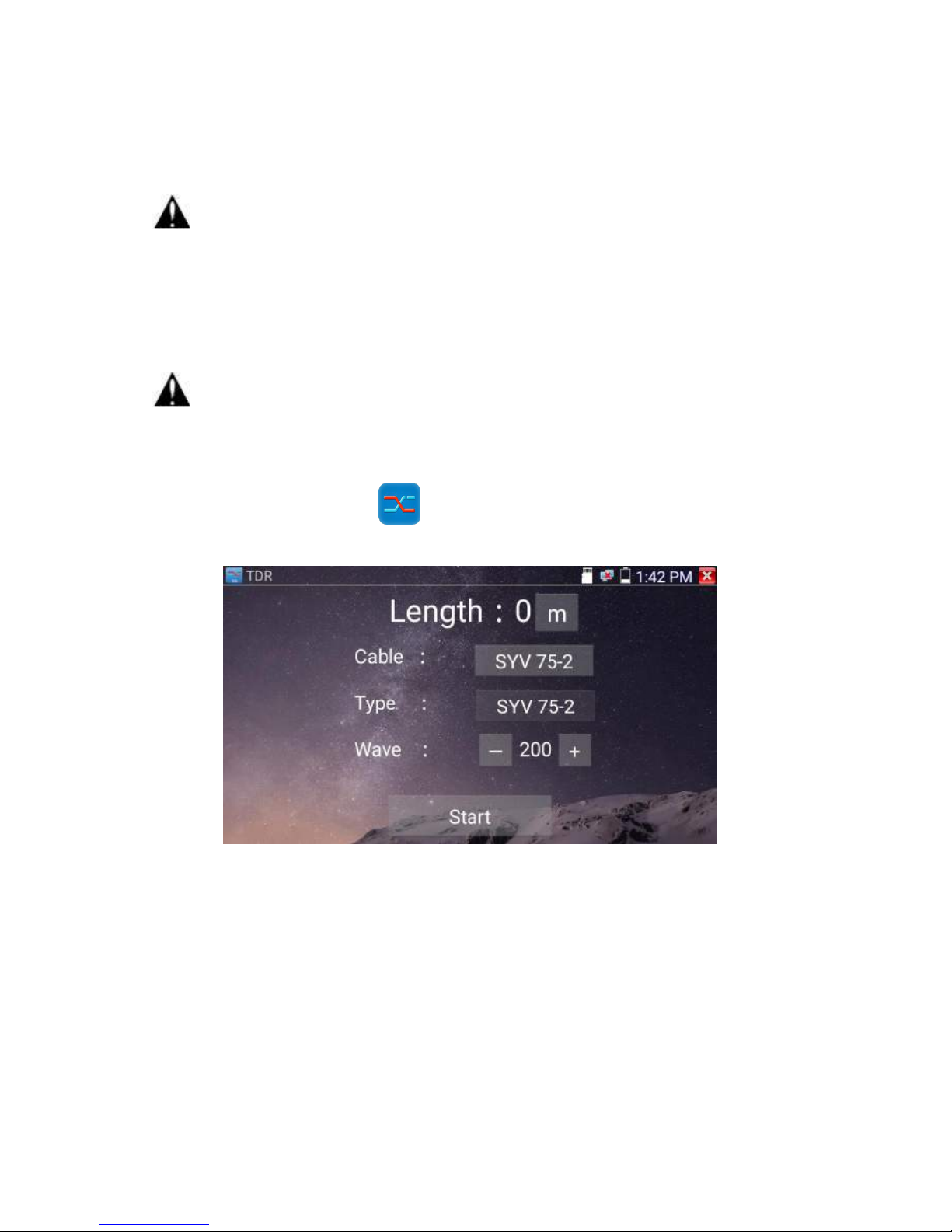
3.3.23 TDR cable test ( *Optional )
Note: The testing cable can’t be connected to any equipment; otherwise it will damage the
tester!
Connect Alligator clip cable to the TDR port, and the cable must connect well before testing, otherwise
it will influence the accuracy. Click to enter, and click “Start” to test
Built-in BNC cable, network cable, RVV control cable, Telephone line and TVVB cable etc can test. 11
groups user-defined cable can be set.
Click “Cable” “Type” to select cable and start testing. One tap on “Start” , do one testing. If select built
in cable type for testing, click “+” and“-” to adjust cable’s wave speed .

Page.79.
User-defined calibration: Choose the cable 100 meters to 200 meters (more than 50 meters) , click
“Cable” , “Type” to select user-defined 1 for calibration, 11 groups user-defined can be set.
1.Select user-defined and click “Calibration “to enter test , click “user-defined 1”can define cable
name,such as:AiPu BNC-5
2. Click “Cable” , “Type” to select cable, and corresponding type, for example, if testing BNC cable,
select “BNC”, if testing communication cable 75-2, select SYV 75-2.

Page.80.
3.Click “+”or“-” to adjust wave speed ,while display length is the same with the actual Length ,click
“Save“to save calibration data . It can be used for the same cable testing next time.
Application:TDR test is the use of pulse reflection method, to transmit pulse signal for tested cable,
when cable is open circuit or short-circuit, reflected pulse is generated, the tester receives and deals with
the reflected wave, measurement results displayed on the screen. TDR can test cable open circuit and
short circuit, help engineer quickly find the cable’s problem location. It is more convenient and efficient
to repair the faulty cable.
Note: The TDR reflect signal could be affected by the cable quality/ cable’s not well
connected etc to cause the different TDR measurement. The TDR measurement is for reference
only.

Page.81.
3.3.24 PoE Voltage test
Click icon to enter PoE voltage measurement
Connect a network cable from a PoE switch to the IP tester’s PSE IN port. Connect an IP camera or
other PoE using node to IP tester’s LAN port, the PoE voltage and the cable’s pin connection status
show on the screen.
Note: This test is for measuring the voltage being drawn by the PoE node and the IP
tester must be between the PoE switch and the PoE node for this test to work.
Note: The PoE switch must be connected to the PSE IN port. The powered device such as IP
camera or other PoE node must be connected to the LAN port.
Note: Do not connect PoE power supply equipment (such as a PoE switch) to the tester’s
UTP/SCAN port; otherwise it will damage the tester.
PSE transmission
When PoE / PSE voltage testing, PoE/PSE conntect to the tester's PSE "IN" port , the camera connetct
to tester's Lan port , tester not only can transmit voltage to supply power for camera ,but also transmit
data at the same time. as well as the computer connect to the PoE/PSE, it can log in connected tester's
PoE camera.

Page.82.
3.3.25 12V power input test
Connect 12V power adaptor to tester’s charging port, then click icon “PoE” to enter voltage
measurement app ,screen show the current adaptor input voltage and power. Note: the current
12V input measured power is the battery charging power and the device working power,the
measured power will change depending on the different of battery power and backlight
brightness.
Warning: Not allow connect device with input power over 17V to tester “12V
IN“port,otherwiseit will damage the machine.

Page.83.
3.3.26 Digital Multi-meter ( *Optional )
Click icon to enter
1) SYMBOLS:
U:DC Voltage Measuring A:DC Current Measuring
Ω:Resistance Measuring :Diode Testing
U~:AC Voltage Measuring A~:AC Current Measuring
:Continuity Testing :Capacitance Measuring
AC/DC
Voltage and current measurement state display
Auto- range
The Multimeter auto adjust the range by input signal or tested components
Data hold
Hold data
Relative
measurement
Display the relative measurement value
Press the key to change display state
10A socket
In 10A current measurement state ,indicate use 10A socket
Over range
The current measurement value over the range, if in the Auto range state, to
switch Auto.
2) OPERATING INSTRUCTION

Page.84.
A. DC Voltage Measuring
a. Connect the black test lead to the “COM ” jack and the red test lead to the “V/Ω” jack.
b.Select U, enter the DC voltage measurement.
c. the tester default Auto range status ,by click “DC auto range” , press the
key can select manual range and restore auto range .
Manual range: 0.000V
6.600V range
00.00V
66.00V range
000.0V
660.0V range
000.0mV
660.0mV rang
B. AC Voltage Measuring
a. Connect the black test lead to the “COM” jack and the red test lead to the “V/Ω” jack.
b. select U ~ , enter the AC voltage measurement.
C.the tester default Auto range status, by click “AC auto range”
d. Manual range can be select , press the key “NEAR” to restore Auto range
e.Manual range: 0.000V 6.600V range
WARNING!
You can’t input the voltage which more than 660V DC, it’s possible to show higher voltage, but it’s
may destroy the inner circuit.
Pay attention not to get an electric shock when measuring high voltage.
WARNING!
You can’t input the voltage which more than 660V AC, it’s possible to show higher voltage, but it’s
may destroy the inner circuit.
Pay attention not to get an electric shock when measuring high voltage.

Page.85.
00.00V
66.00V range
000.0V
660.0V range
000.0mV
660.0mV range
C. DC Current Measuring (only manual range )
a. Connect the black test lead to the “COM ” jack and the red test lead to the “mA” jack for a maximum
of 660mA current. For a maximum of 10A, move the red lead to the 10A jack.
b.select A, enter the DC current measurement,the screen display“DC current ”, can select manual
range;
c.Manual range: 0.000mA 6.6mA range
00.00mA 66.00mA range
000.0mA 660.0mA range
00.00A 10.00A range(use 10A socket)
d. Select the range to enter current measurement
NOTE:
When only the figure “OL” is displayed, it indicates over range situation and the higher range has to
be selected.
When the value scale to be measured is unknown beforehand, set the range selector at the highest
position.
The maximum current of mA socket is 660mA, over-current will destroy the fuse, and will damage
the meter.
The maximum current of 10A socket is 10A, over-current will destroy the meter, and will damage
WARNING!
Shut down the power of the tested circuit, and then connect the meter with the circuit for
measurement.

Page.86.
the operator.
D. AC Current Measuring (Only Manual range)
a. Connect the black test lead to the “COM” jack and the red test
lead to the“mA” jack for a maximum of 660mA current. For a
maximum of 10A, move the red lead to the 10A jack.
b. select A~, enter the AC current measurement, manually select
the range
c. Manual range: 0.000mA 6.600mA range
00.00mA 66.00mA range
000.0mA 660.0mA range
00.00A 10.00A range(use 10A socket)
Note:
When only the figure “OL” is displayed, it indicates over range situation and the higher range has to
be selected.
When the value scale to be measured is unknown beforehand, set the range selector at the highest
position.
The maximum current of mA socket is 660mA; over-current will destroy the fuse, and will damage
the meter.
The maximum current of 10A socket is 10A, over-current will destroy the meter, and will damage
the operator.
WARNING!
Shut down the power of the tested circuit, and then connect the meter with the circuit for
measurement.

Page.87.
In“ AC ” mode, only can input “AC ”, if not, will damage the meter.
E. Resistance Measuring
a. Connect the black test lead to the “COM ” jack and the red test lead to the “V/Ω” jack.
b. to select Ω, enter the Ω measurement
the tester default Auto range status, Press the key manually select
range ,Press “NEAR” to restore “Auto range”
Manual range:(Connect the red lead to black leads, will display the
measure range)
000.0Ω
660Ω range
0.000 KΩ
6.600KΩ range
00.00 KΩ
66.00KΩ range
000.0 KΩ
660.0KΩ range
0.000 MΩ
6.600MΩ range
00.00 MΩ
66.00MΩ range
F. Continuity Testing
a. Connect the black test lead to the “COM” jack and the red test lead to the “V/Ω” jack.
b.to select , enter the continuity test, Connect test leads across two point
of the circuit under testing.
c. If continuity exists (i.e., resistance less than about 50Ω), built-in buzzer
will sound.
WARNING!
When measuring in-circuit resistance, be sure the circuit under test has all power removed and
that all capacitors have discharged fully.
WARNING!
When testing the circuit continuity, be sure that the power of the circuit has been shut down and all
capacitors have been discharged fully.

Page.88.
G. Diode Testing
a. Connect the black test lead to the “COM” jack and the red test lead to
the “V/Ω” jack. (the red lead anode “+” )
b. to select , enter the diode testing.
c. Connect test red lead across to the anode, the black lead to the
cathode of the diode under testing.
d. Connect test red lead across to the cathode, the black lead to the anode of the diode under testing.
e .Tested diode, forward voltage low 30mv,there is sound indication ,then can finish the testing quickly
without view the screen.
H. Capacitance Measuring
a. Connect the black test lead to the“ COM ” jack and the red test lead to the “V/Ω ” jack.
b. Select “ ” to enter, enter the capacitance measurement.
c. The tester default auto range status, and manual range by press upward and downward key, Auto rang
by press the key “NEAR”
Manual range: 0.000nF
6.600nF range
00.00nF
66.00nF range
000.0nF
660.0nF range
0.000uF
6.600μF range
WARNING!
The capacitance of a capacitor should be tested separately, should not test in the installation
of circuit.
WARNING!
To avoid electric shock, be sure the capacitors have been discharged fully before measuring the
capacitance of a capacitor.

Page.89.
00.00uF
66.00μF range
000.0uF
660.0μF range
0.000mF
6.600mF range
00.00mF
66.00mF range
d. Before connect test leads across two sides of the capacitor under measurement, be sure that the
capacitor has been discharged fully.
Note:
a. The capacitance of a capacitor should be tested separately, should not test in
the installation of circuit.
b. To avoid electric shock, be sure the capacitors have been discharged fully before measuring the ca
pacitance of a capacitor.
c. While testing the capacitance of a capacitor to
660uF, the Max time will be 6.6 seconds, if the capacitor is leaked or damaged,
the data can’t be read. The tester will be normal after disconnecting the capacitor.
Manual range and Auto range
When testing, click “Range select " to change the value, click “Auto range “to enter Auto
measurement
Data hold

Page.90.
Click “Hold data” to enter, the data be hold, the value is green. Press it again to quit.
Relative value measurement
Click “Relative “to enter, the tester Auto-save the data, the displayed new measurement and
relative value is red color. Press it again to quit
The hold function and the relative value be combined use, the display value is yellow
The meter protection
Voltage protection
You can’t input the voltage which more than 660V AC, it’s possible to show higher voltage, but
it’s may destroy the inner circuit.
Resistance, Continuity, Diode, PTC component Protection
Wrong input voltage, will Auto enter protection state , It only suitable for short and limit time work.
If input voltage over 600V, will damage the meter.
mA current fuse range: 250V 1A
if the current over the rated range ,fuse will melt to protect the meter .Pls use the same model when
change the fuse, Pls opens the battery cover to change.
Note: 10A socket without fuse protection, if over the current range
Wrong using the 10A socket to measure the voltage, will damage the meter.
3.3.27 Optical power meter ( *Optional )
Click icon to enter ,with five wavelength 1625nm,1550nm , 1490nm , 1310nm ,1300nm ,
850nm ,linear or nonlinear optical power display, both for optical power testing and Fiber link loss
relative measurement . It is necessary tool for installation and maintenance optical fiber communication,
cable television and CCTV security system.
Note: Please keep the fiber connector and the dust cap be clean, and clean the detector with the special

Page.91.
alcohol.
Data hold
While testing, click “Hold” to data hold, the data will not change. It’s convenient to read. Press
again to quit.
Relative power value (optical link loss) measurement
While testing, set the wavelength for measurement. Click “relative”(difference) to test, the tester Auto
save current fiber power value as the base reference value. Input another optical fiber to be measured,
the displayed new measurement and relative value is red color. Press it again to quit.

Page.92.
Data hold and Relative measuring use together, the data is yellow while the function is effect.
3.3.28 Visual Fault Locator ( *Optional )
Click icon to enter
VFL four status can select——“Steady mode”, “Evasive 1Hz”,“Evasive 2Hz”and“Time off”. Click
button “Steady mode” to enter steady status, click button “Evasive 1Hz” and “Evasive 2Hz, to enter
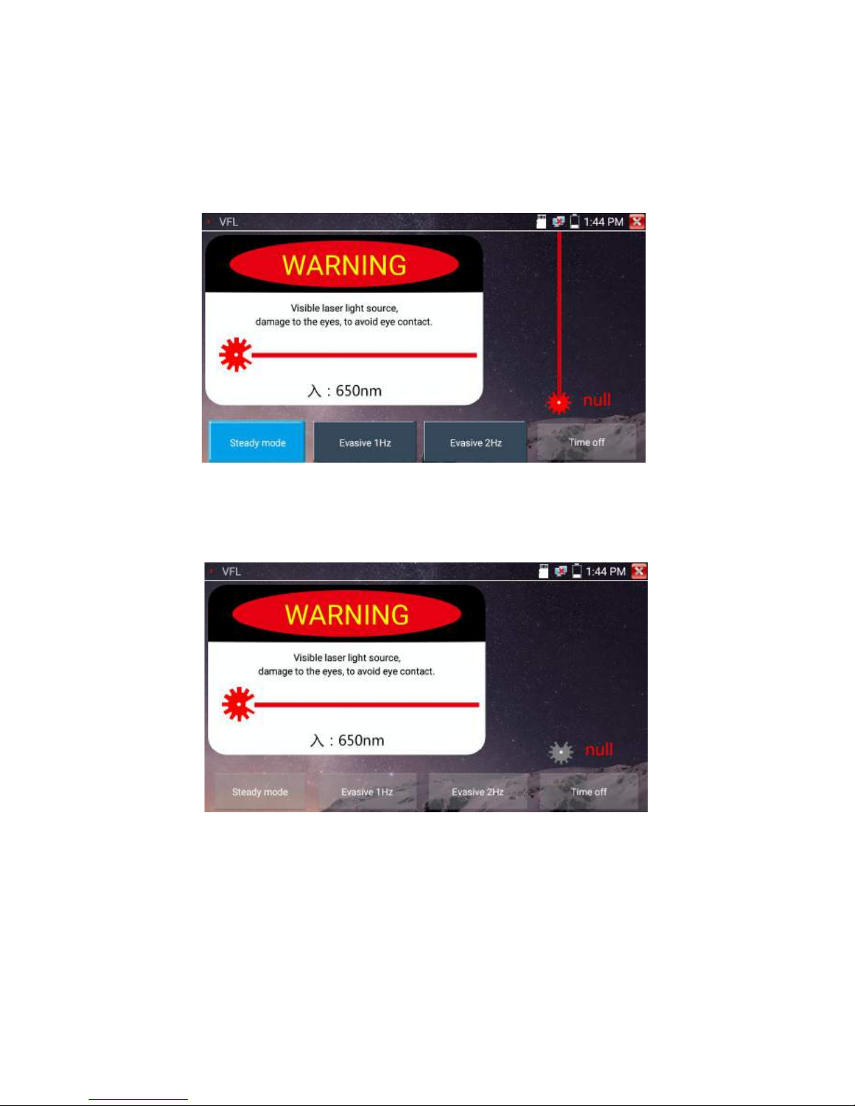
Page.93.
pulse mode, click button “Time off”, VFL is turned off. Timed turn off can select (5 mins, 10 mins, 30
mins, 60 mins and 120 mins).
Click” Steady mode”, red laser source emits steady, click again to quit.
Click icons “Evasive 1Hz”or“Evasive 2Hz”to enter pulse mode, the red laser source is emitted by a
certain frequency, press it again to quit

Page.94.
3.3.29 Audio Record
Connect an audio device to the IP tester’s audio input port. Click the icon to enter the Audio
Recorder app. Click the red button to stop, and the unit will prompt you to save the recording
3.3.30 Data monitor
Pls click icon to enter
Click “Setting” to choose the baud rate of RS485/RS232; it must be the same as the DVR or the Control
keyboard .The DVR or Control keyboard send the code to the tester, if it can be read, the protocol will
shown on the upper right, like Pelco D, if not, like P:---
While the tester receives the code, press the key to empty.
Though the RS485 port, display the PTZ control code of the multifunctional keyboard or the DVR.
Controller can check the status of the RS485 transmission through the code on the display. (The RS485
communication rate must be the same.)
Application: Check the RS485 communication states of the video optical transmitter whether normal.
Engineer can analyze the protocol and check the data through the displayed code.

Page.95.
3.3.31 Audio player
Click the icon to enter . The audio player only supports MP3 format Audio files.
3.3.32 Media Player
Click the icon to enter
The Media player can browse video and image files. It supports the video formats of MP4, H.264,
MPEG4, and MKV. The IP tester recorded files can play directly via the Media player. The Media
player will automatically display the video files from the SD card. Click on the desired file to play.
Click RETURN to exit.
To rename or delete an existing file, press the file name for a few seconds until the screen below
 Loading...