

Page 1
ASSEMBLY & INSTALLATION
INSTRUCTION FOR #120/121
Please read carefully and save these instructions, as you may need them at a later date.
GENERAL
All electrical connections must be in accordance with local and National Electrical Code (N.E.C.) standards. If
you areunfamiliar with proper electrical wiring connections obtain the services of a qualified electrician.
Remove the fixture and the mounting package from the box and make sure that no parts are missing by
referencing the illustrations on the installation instructions.
CAUTION
Turn off the main power at the circuit breakerbefore installing the fixture, in order to prevent possible shock.
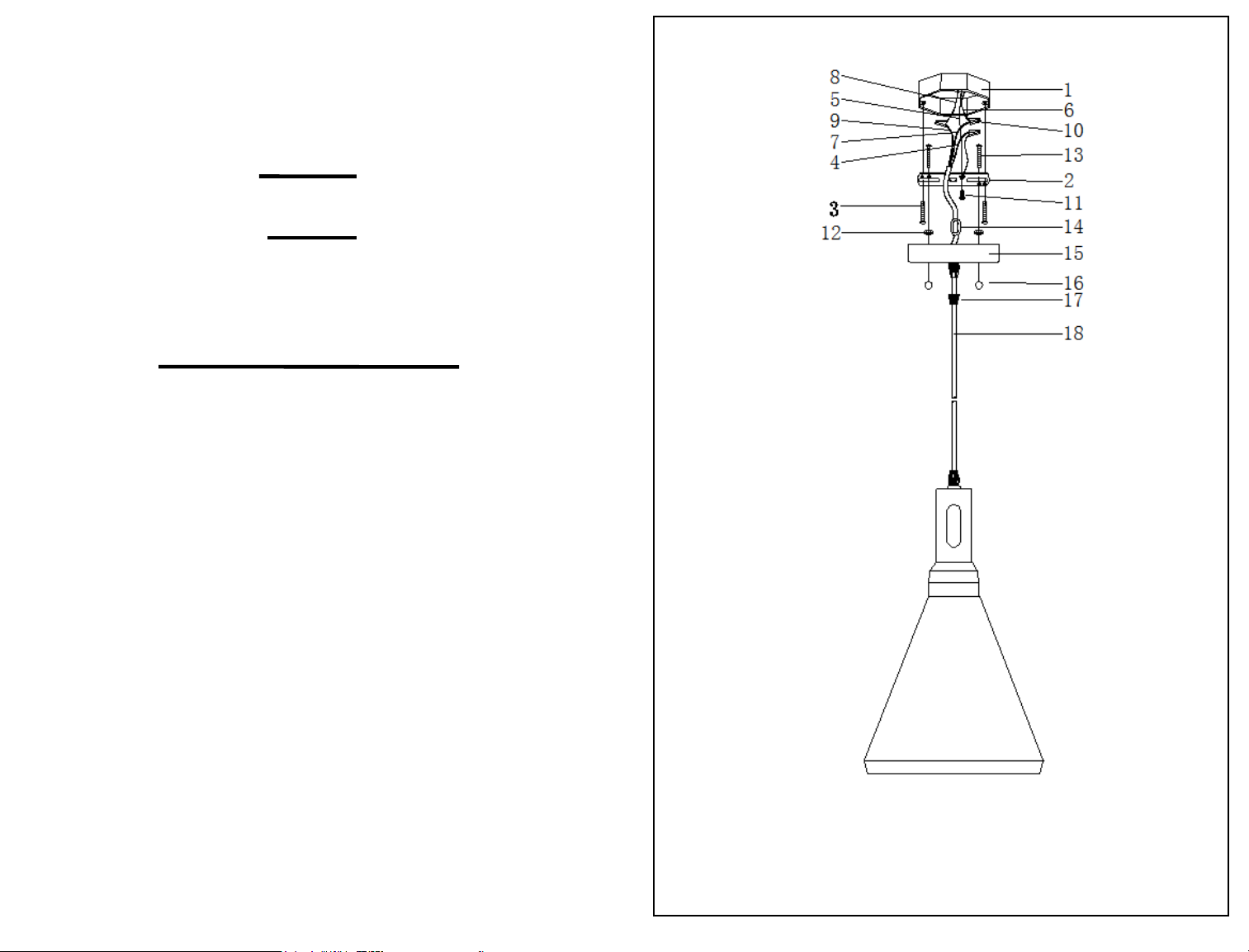
17. FEMALE CONNECTOR
18. CORD
FIG
ASSEMBLY AND INSTALLATION
1. Unscrew FEMALE CONNECTOR(17) and adjust the CORD(18) to your desired length(if wire cut
needed, please ensure exposed wire is about 1/2”).
2. After the adjustment of the length of the cord, please slide the “8”WIRE CLAMP(14) near to the
COVER PLATE, then screw the FEMALE CONNECTOR(17) till tight.
2. Screw the FIXTURE MOUNTING SCREWS (13) into the BACK PLATE (2) and thread the HEX
NUTS (12) onto the FIXTURE MOUNTING SCREWS (13), as shown. Secure the position of the
FIXTURE MOUNTING SCREWS (13) by tightening the HEX NUTS (14) against the BACK PLATE
(2).
3. Secure the BACK PLATE (2) to the OUTLET BOX (1) with MOUNTING SCREWS (3).
4. Attach the BLACK SUPPLY WIRE (8) to the BLACK FIXTURE LEAD WIRE (9) by using the
WIRE CONNECTOR (10). At the same manner, attach the WHITE SUPPLY WIRE (6) to the
WHITE FIXTURE LEAD WIRE (7). Loop the SUPPLY GROUND WIRE (5) around the GROUND
SCREW (11) of the BACK PLATE (2). (Note: Be sure to provide an extra 3” length of the SUPPLY
GROUND WIRE (5) for connection to the FIXTURE GROUND WIRE (4).) Tighten the GROUND
SCREW (11). Connect the remaining SUPPLY GROUND WIRE (5) to the GREEN FIXTURE
GROUND WIRE (4) using a WIRE CONNECTOR (10). Place wiring and connections inside the
OUTLET BOX (1).
5. Place the COVER PLATE (15) onto the FIXTURE MOUNTING SCREWS (13), and secure it into
place using the DECORATIVE NUTS(16)provided.
6. Screw light bulb into the socket and make sure it does not exceed the maximum wattage
specified on the fixture’s wattage rating label.
INSTALLATION IS NOW COMPLETED
1. OUTLET BOX
2. BACK PLATE
3. MOUNTING SCREW
4. FIXTURE GROUND WIRE
5. SUPPLY GROUND WIRE
6. WHITE SUPPLY WIRE
7. WHITE FIXTURE LEAD WIRE
8. BLACK SUPPLY WIRE
9. BLACK FIXTURE LEAD WIRE
10. WIRE CONNECTOR
11. GROUND SCREW
12. HEX NUTS
13. FIXTURE MOUNTING SCREW
14. “8” WIRE CLAMP
15. COVER PLATE
16. DECORATIVE NUT
 Loading...