

Page 1
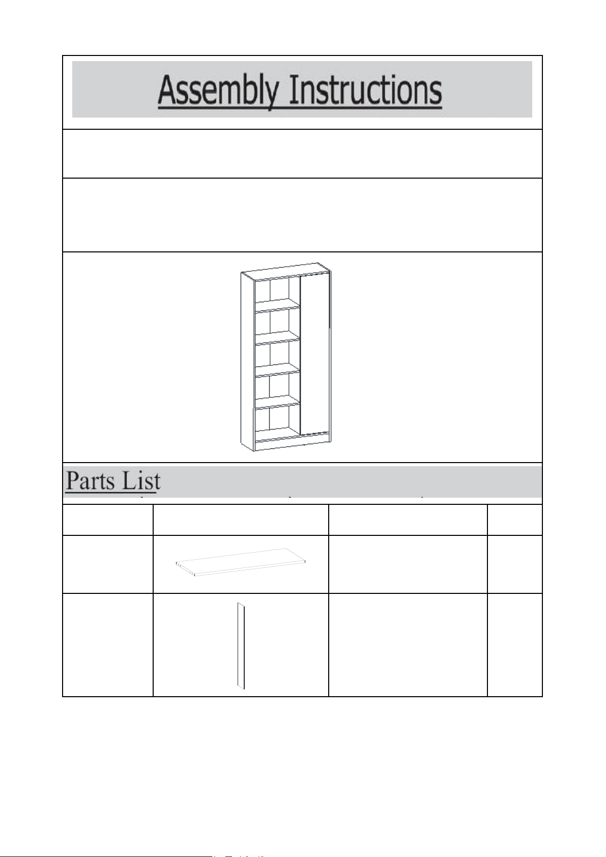
Label Picture Description QTY
A Top Panel 1
B Left Side Panel 1
Caution : You must read this before you proceed
BOOKCASE
Page 1 OF 18
Page 2
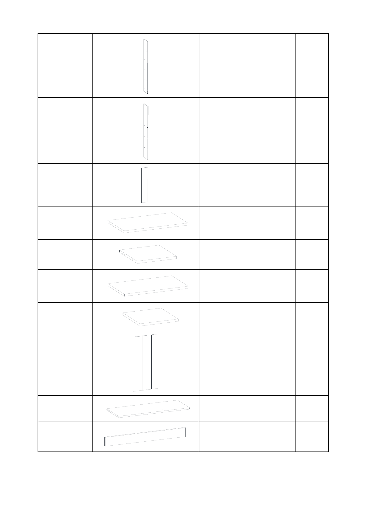
C Right Side Panel 1
D Center Panel 1
E Door Panel 1
F Long Middle Panel 1
G Short Middle Panel 1
H Long Shelf Panel 3
I Short Shelf Panel 3
J Back Panel 1
K Bottom Panel 1
L Leg Panel 2
Page 2 OF 18
Page 3
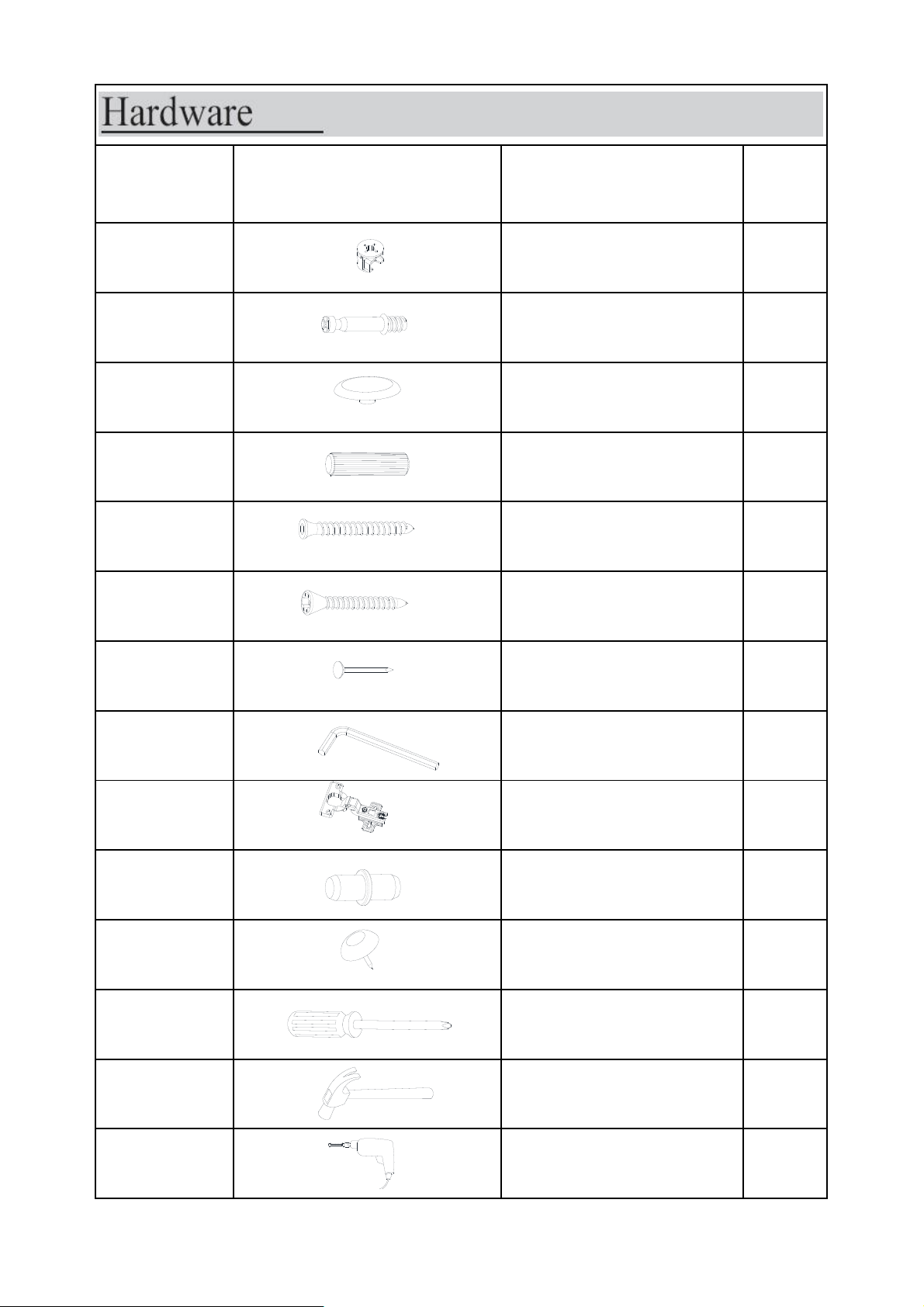
Label Picture Description QTY
① Cam Lock 19
② Cam Bolt 19
③ Cam Cap 19
④
Positioning Dowel
(8*30mm)
29
⑤
Cap Wood Screw
(6*50mm)
3
⑥ Screw (3.5*16mm) 13
⑦ Nail 41
⑧ Allen Key 1
⑨ Connector 3
⑩ Shelf Support 25
⑪ PVC Nail Leg 9
⑫
Screwdriver (not
provided)
1
⑬
Hammer (not
provided)
1
⑭
Power Drill (not
provided)
1
Page 3 OF 18
Page 4
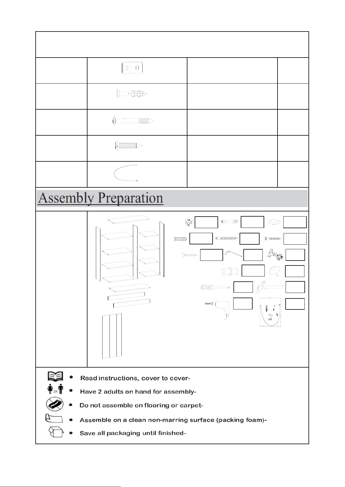
⑮ Metal Bracket 4
⑯ Wall Plug 2
⑰
Wall Plug Screw 2
⑱
Pan Head Screw 2
⑲
Cabinet Restraint
Strap
2
Cabinet Restraint Device Hardware
Before
Beginning
Assembly:
X 19
X 19
X 19
X 29
X 3
X 13
X 41
X 1
X 3
X 25
X 1
X 1
X 1
X 2
X 9
Page 4 OF 18
Page 5
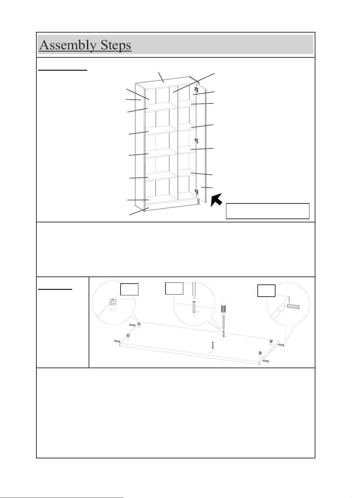
Step 1
Overview
Unpack and place all parts on a clean, non-marring surface.
1.1) Insert Cam Locks(①) into mounting positions on Top
Panel(A) by hand.
1.2) Insert Positioning Dowel(④) into mounting positions on Top
Panel(A) by hand.
1.3) Attach Cam Bolts(②) to mounting positions on Top Panel(A)
with Screwdriver(⑫).
This Bookcase has multiple parts and may require up to 60 minutes to
assemble. To give you an overview of the Bookcase parts, the above picture
is to help you put the various parts into perspective. Please read through the
instructions below to familiarise yourself with the parts and steps before
assembly.
Short Shelf Panel (I)
FRONT FACING
Top Panel (A)
Left Side Panel (B)
Back Panel (J)
Right Side Panel (C)
Center Panel (D)
Door Panel (E)
Long Middle Panel (F)
④
A
⑫
②
②
④
②
1.2
Long Shelf Panel (H)
Long Shelf Panel (H)
Long Shelf Panel (H)
Bottom Panel (K)
Leg Panel (L)
1.1
1.3
⑫
①
④
④
④
①
①
①
①
Short Shelf Panel (I)
Short Shelf Panel (I)
Short Middle Panel (G)
Page 5 OF 18
Page 6
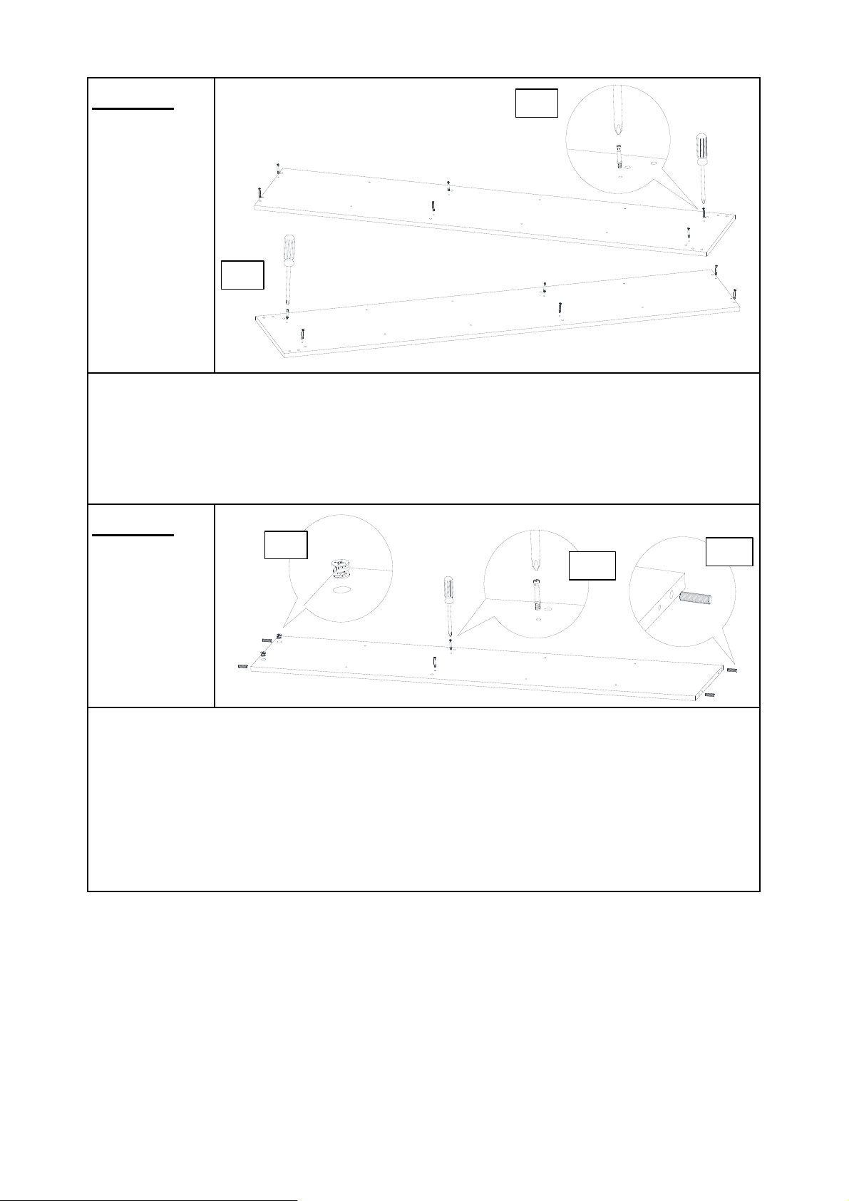
Step 2
Step 3
3.1) Insert Positioning Dowels(④) into mounting positions on
Center Panel(D) by hand.
3.2) Insert Cam Locks(①) into mounting positions on Center
Panel(D) by hand.
3.3) Attach Cam Bolts(②) to mounting positions on Center
Panel(D) with Screwdriver(⑫).
2.1) Attach Cam Bolts(②) to mounting positions on Left Side
Panel(B) with Screwdriver(⑫).
2.2) Attach Cam Bolts(②) to mounting positions onRight Side
Panel(C) with Screwdriver(⑫).
B
①
⑫
②
D
C
⑫
②
3.2
3.3
①
①
②
②
⑫
3.1
④
2.1
2.2
Page 6 OF 18
Page 7
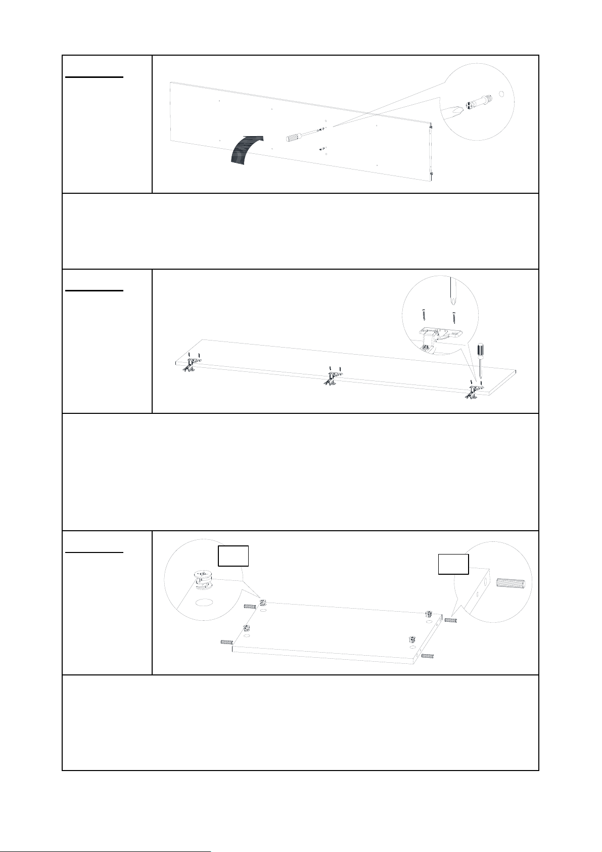
Step 4
Step 5
Step 6
Lift Center Panel(D) upward with help from another adult.
Attach Cam Bolts(②) to mounting positions on the opposite side of
Center Panel(D) with Screwdriver(⑫).
Attach Connectors(⑨) to Door Panel(E) with Screws(⑥) using
Screwdriver(⑫).
Tighten the Screws fully in a sequential manner.
Note: There are pre-existing mounting positions on the Door
Panel(E) to attach the Connectors(⑨).
6.1) Insert Cam Locks(①) into mounting positions on Long Middle
Panel(F) by hand.
6.2) Insert Positioning Dowels(④) into mounting positions on Long
Middle Panel(F) by hand.
E
D
④
④
④
①
①
④
⑥
F
①
⑫
②
⑫
②
②
⑥
⑫
⑨
⑨
⑨
⑨
6.1
6.2
④
①
①
Page 7 OF 18
Page 8
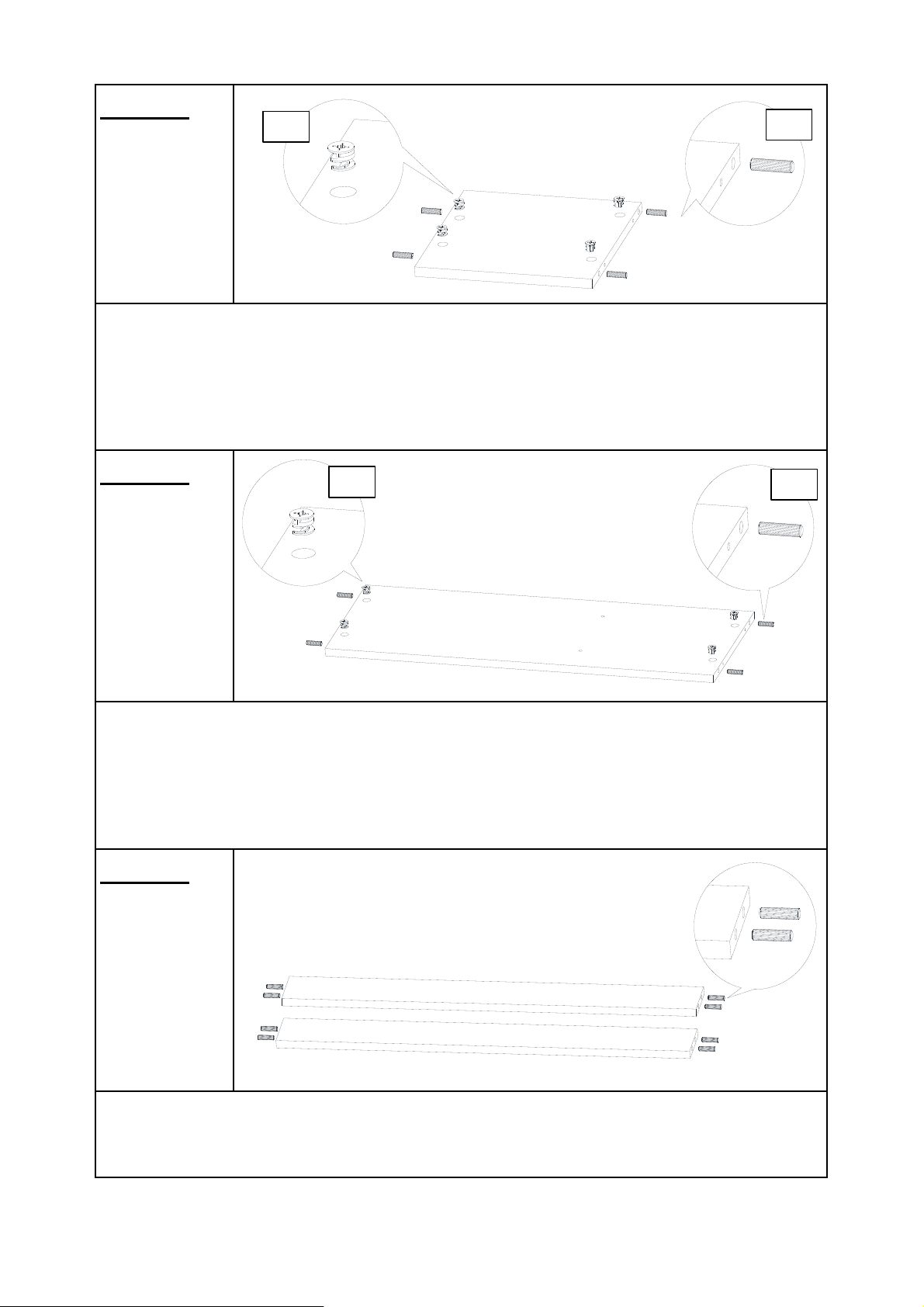
Step 7
Step 8
Step 9
7.1) Insert Cam Locks(①) into mounting positions on Short Middle
Panel(G) by hand.
7.2) Insert Positioning Dowels(④) into mounting positions on Short
Middle Panel(G) by hand.
8.1) Insert Cam Locks(①) into mounting positions on Bottom
Panel(K) by hand.
8.2) Insert Positioning Dowels(④) into mounting positions on
Bottom Panel(K) by hand.
Insert Positioning Dowels(④) into mounting positions on Leg
Panels(L) by hand.
④
G
①
④
④
K
④
①
①
①
④
L
7.1
7.2
①
①
①
④
④
④
8.2
8.1
④
④
④
①
①
①
④
L
Page 8 OF 18
Page 9
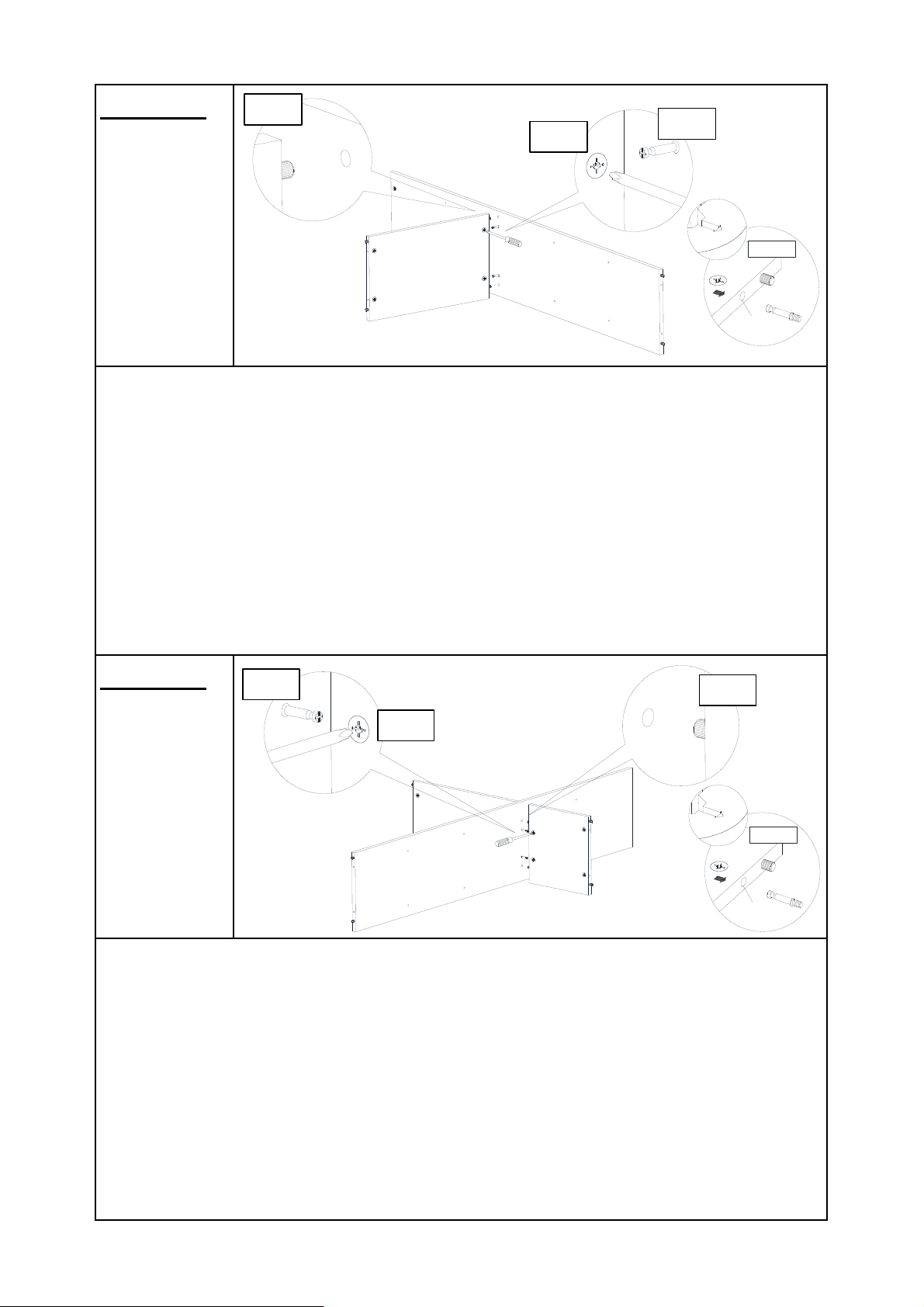
Step 10
Step 11
10.1) Insert Positioning Dowels(④) from Long Middle Panel(F) into
mounting positions on Center Panel(D).
Note: Ensure the arrows on Cam Locks head points towards
the Cam Bolt mounting positions.
10.2) Insert the mounting positions on side of Long Middle
Panel(F) onto Cam Bolts(②) on Center Panel(D).
10.3) Turn the Cam Locks(①) clockwise with the Screwdriver(⑫)
until they all lock into place.
11.1) Insert Positioning Dowels(④) from Short Middle Panel(G)
into mounting positions on Center Panel(D).
Note: Ensure the arrows on Cam Locks head points towards
the Cam Bolt mounting positions.
11.2) Insert the mounting positions on side of Short Middle
Panel(G) onto Cam Bolts(②) on Center Panel(D).
11.3) Turn the Cam Locks(①) clockwise with the Screwdriver(⑫)
until they all lock into place.
D
④
②
⑫
①
②
G
D
F
④
10.1
F
①
⑫
10.2
10.3
11.2
11.3
11.1
Arrow
NOTE
Cam Bolt
Mounting Position
Arrow
NOTE
Cam Bolt
Mounting Position
①①④
②
①
①④②
Page 9 OF 18
Page 10
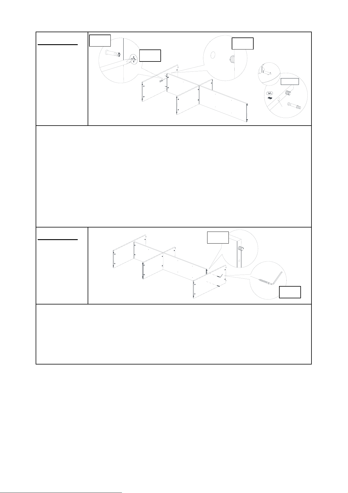
Step 12
Step 13
13.1) Insert Positioning Dowels(④) from Center Panel(D) into
mounting positions on Bottom Panel(K).
13.2) Attach Bottom Panel(K) to Center Panel(D) with Cap Wood
Screws(⑤) using Allen Key(⑧).
12.1) Insert Positioning Dowels(④) from Center Panel(D) into
mounting positions on Top Panel(A).
Note: Ensure the arrows on Cam Locks head points towards
the Cam Bolt mounting positions.
12.2) Insert the mounting positions on side of Center Panel(D)
onto Cam Bolts(②) on Top Panel(A).
12.3) Turn the Cam Locks(①) clockwise with the Screwdriver(⑫)
until they all lock into place.
A
④
D
D
⑫
①
④
12.1
F
G
②
12.2
12.3
K
13.1
13.2
⑧
⑤
Arrow
NOTE
Cam Bolt
Mounting Position
①
①④②
Page 10 OF 18
Page 11
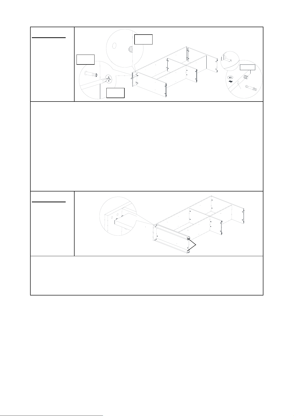
Step 14
Step 15
Insert Positioning Dowels(④) from two Leg Panel(L) into mounting
positions on Left Side Panel(B).
14.1) Insert Positioning Dowels(④) from Top Panel(A) and Bottom
Panel(K) into mounting positions on Left Side Panel(B).
Note: Ensure the arrows on Cam Locks head points towards
the Cam Bolt mounting positions.
14.2) Insert the mounting positions on side of Top Panel(A) and
Bottom Panel(K) onto Cam Bolts(②) on Left Side Panel(B).
14.3) Turn the Cam Locks(①) clockwise with the Screwdriver(⑫)
until they all lock into place.
K
⑫
④
④
L
②
①
14.1
14.2
14.3
B
④
B
A
Arrow
NOTE
Cam Bolt
Mounting Position
①①④
②
B
L
Page 11 OF 18
Page 12
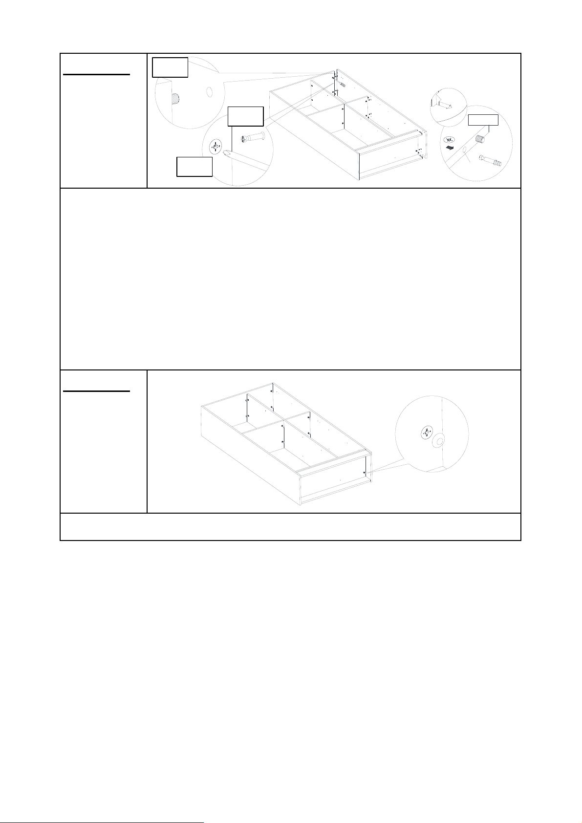
Step 16
Step 17
16.1) Insert Positioning Dowels(④) from Top Panel(A) and Bottom
Panel(K) into mounting positions on Right Side Panel(C).
Note: Ensure the arrows on Cam Locks head points towards
the Cam Bolt mounting positions.
16.2) Insert the mounting positions on side of Top Panel(A) and
Bottom Panel(K) onto Cam Bolts(②) on Right Side Panel(C).
16.3) Turn the Cam Locks(①) clockwise with the Screwdriver(⑫)
until they all lock into place.
Attach Cam Caps(③) to all Cam Locks(①) by hand.
④
②
⑫
①
16.1
16.2
16.3
C
K
①
③
A
Arrow
NOTE
Cam Bolt
Mounting Position
①
①
④
②
③
③
③
③
③
③
③
③
③
③
③
③
③
③
③
③
③
③
Page 12 OF 18
Page 13
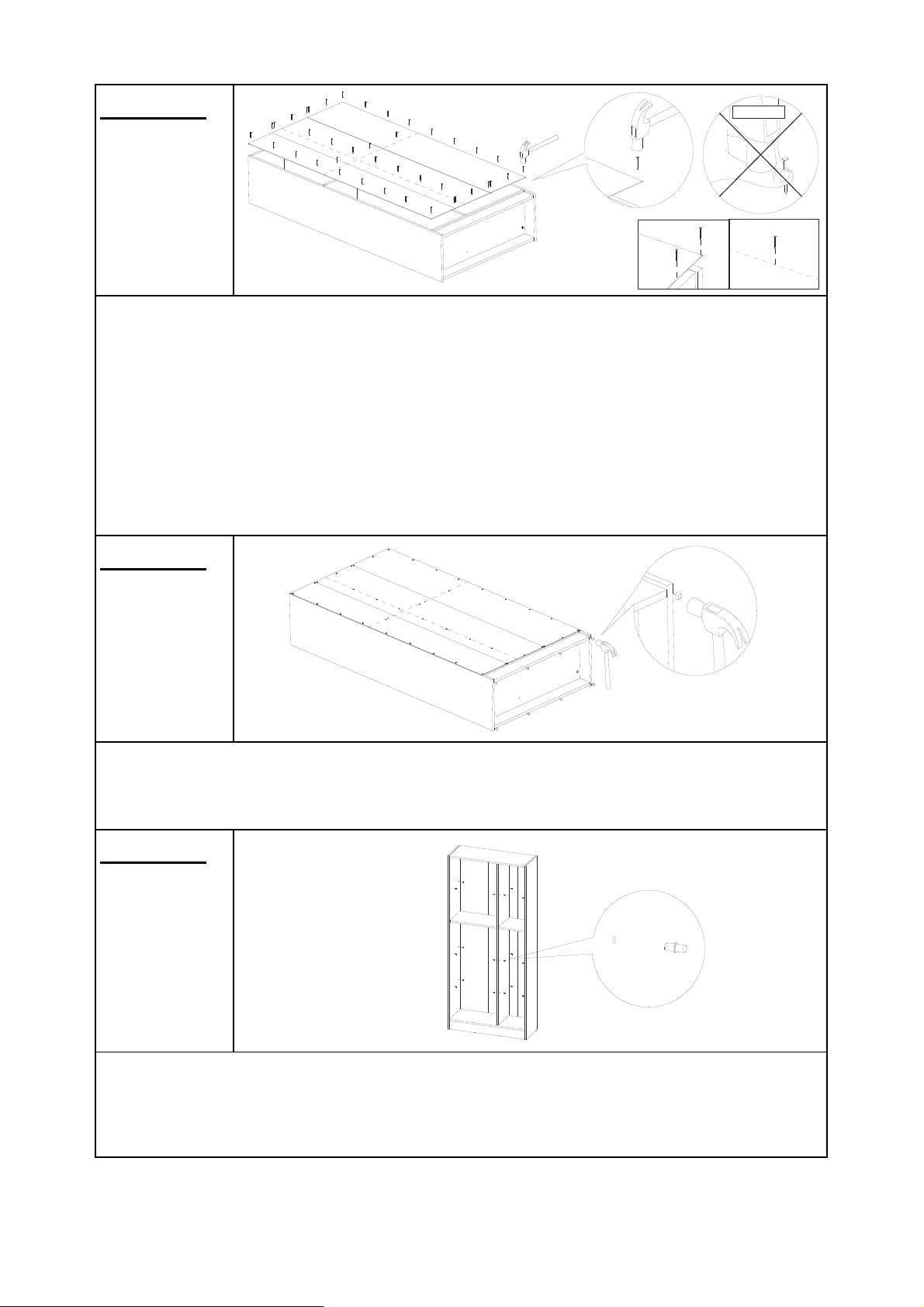
Step 18
Step 19
Step 20
Flip the whole Bookcase over.
Attach Back Panel(J) to Bookcase Assembly using Nails(⑦) with
Hammer(⑬).
Please be extra careful when using a hammer to avoid injury.
Note: Hit Nails along all four edges (slightly inwards from
sides) on the lines drawn on the Back Panel(J).
Attach PVC Nail Legs(⑪) to the Base of the assembled Bookcase
with Hammer(⑬).
Insert Metal Shelf Support(⑩) into mounting positions on Left Side
Panel(B), Right Side Panel(C), and Center Panel(D) by hand.
CAUTION
⑦
J
⑬
⑪
⑬
B
C
D
⑩
Note
⑦
⑦
⑦
D
Page 13 OF 18
Page 14
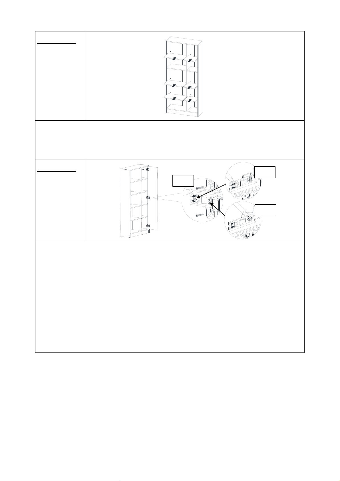
Step 21
Step 22
22.1) Attach Connectors(⑨) to Right Side Panel(C) using
Screws(⑥) with Screwdriver(⑫).
Tighten the Screws fully in a sequential manner.
22.2) Rotate first screw on Connectors(⑨) to adjust left-right
position of Door Panel(E) when necessary.
22.3) Rotate second screw on Connectors(⑨) to adjust in-out
position of Door Panel(E) when necessary.
Note: There are pre-existing mounting positions on the Right
Side Panel(C) to attach the Connectors(⑨) .
Put Long Shelf Panels(H) and Short Shelf Panels(I) in place on
Shelf Supports(⑩).
H
I
E
C
22.1
22.2
22.3
⑨
⑥
⑥
⑫
H
H
I
I
Page 14 OF 18
Page 15
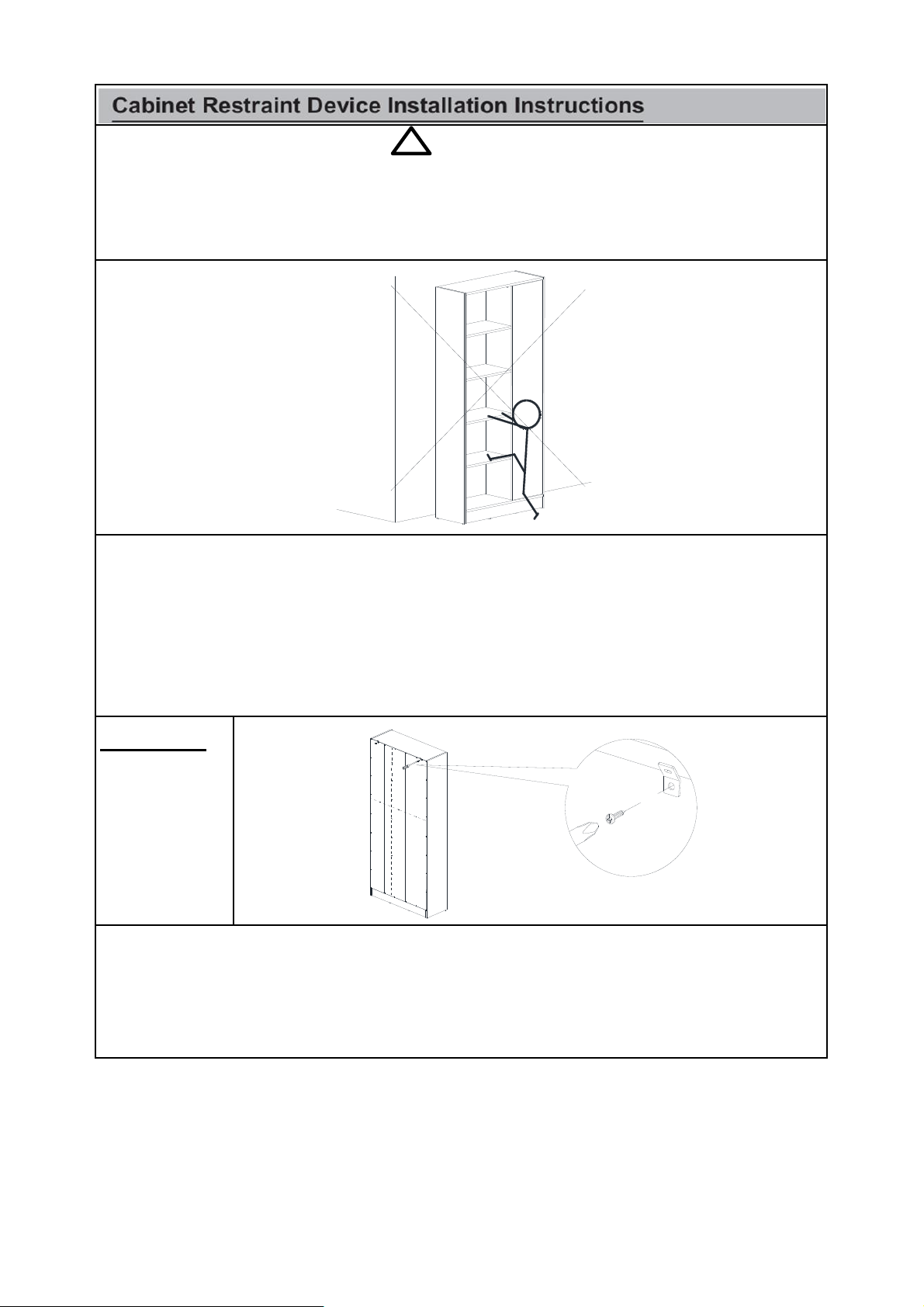
Step 23
23.1) Turn the Bookcase so the back side faces you.
23.2) Attach Metal Brackets(⑮) to Back Panel(J) using Pan Head
Screws(⑱) with Screwdriver(⑫).
! WARNING
Serious or fatal crushing injuries can occur from tipping furniture.
To help prevent tip-over: ALWAYS secure this furniture to the wall using Cabinet
Restraint Device.
See product instructions for more ways to help prevent furniture tip-over.
Usage For Cabinet Restraint Device:
To Secure Bookcase against wall, attach Metal Brackets(⑮) to
wall and product, and use Cabinet Restraint Straps(⑲) to connect
the Metal Brackets(⑮).
Instructions:
⑱
⑮
J
⑫
⑮
⑮
Page 15 OF 18
Page 16
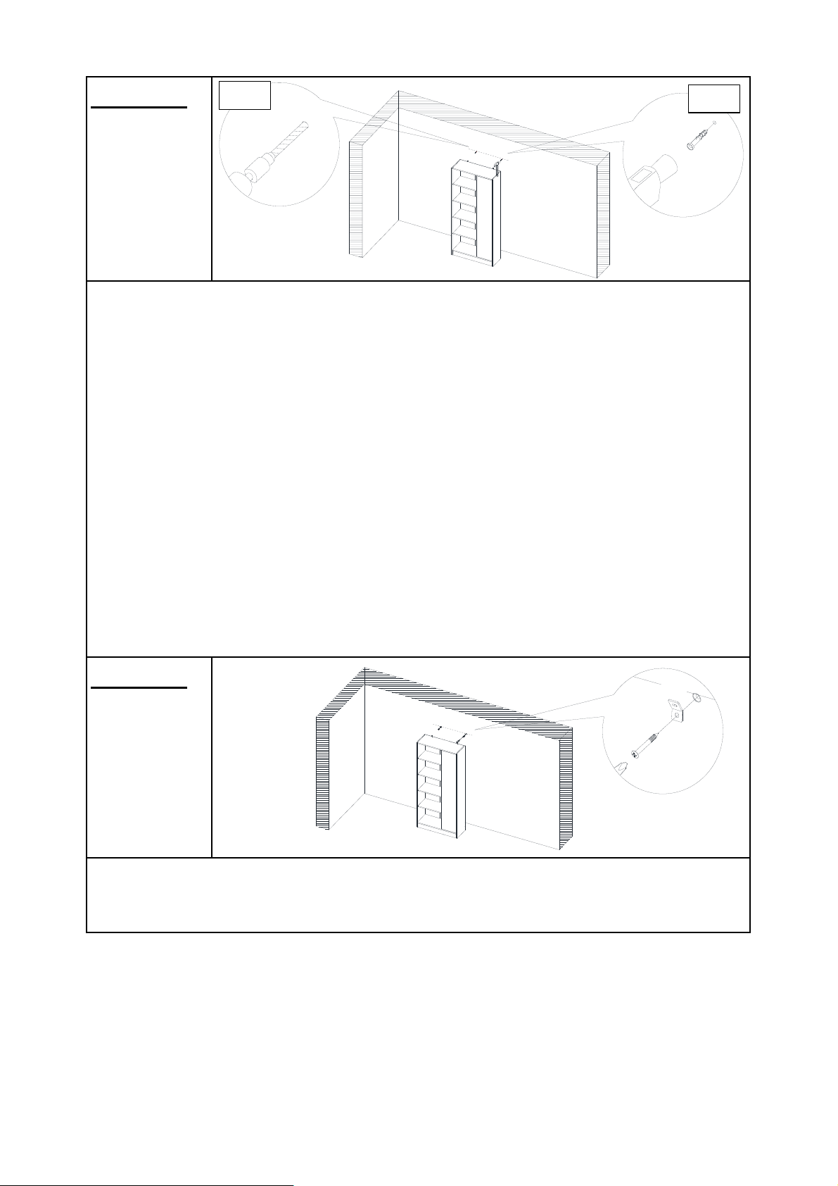
Step 24
Step 25
24.1) Drill two holes on wall at same height as Metal Brackets(⑮)
on Bookcase with Power Drill(⑭).
You can mark these points in two ways as below:
1) Move the Bookcase back to the wall. Mark two points same
height as Bookcase on the wall.
Note: The Metal Brackets need to be secured to solid, load
bearing surface. Please use a Stud Finder(not supplied) if
needed to locate the Wall Frame.
2) Measure the height of the Metal Brackets(⑮) with
ruler/measuring tape and mark on wall to keep them accurate and
same height.
24.2) Insert Wall Plugs(⑯) into holes on wall with Hammer(⑬).
Attach Metal Brackets(⑮) to Wall Plugs(⑯) using Wall Plug
Screws(⑰) with Screwdriver(⑫).
⑬
⑮
⑰
⑫
⑯
⑭
24.2
24.1
⑯
⑯
⑯
⑮
⑮
Page 16 OF 18
Page 17
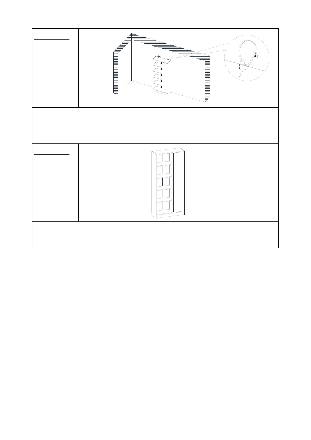
Step 26
Step 27
Move the Bookcase back against wall. Pull the Restraint
Straps(⑮) through the Metal Brackets(⑮) on the wall and
Bookcase one by one, and pull the Restraint Straps(⑲) tight.
Your Bookcase is ready for use.
This Bookcase can only be used on a flat, level surface.
⑮
⑲
⑮
⑲
⑲
Page 17 OF 18
Page 18
Page 18 OF 18
 Loading...