

Page 1

FUSEFORCE
Hand Fixation System
SURGICAL TECHNIQUE
®
Page 2

Contents
Chapter 1 3
Chapter 2 4
Appendix A 7
Intended Use
Surgical Technique
Ordering Information
Indication Sizing Reference
Proper surgical procedures and techniques are the responsibility of the medical professional. The following
guidelines are furnished for information purposes only as techniques used by the design surgeons. Each
surgeon must evaluate the appropriateness of the procedures based on his or her personal medical
training and experience. Prior to use of the system, the surgeon should refer to the product package
insert for complete warnings, precautions, indications, contraindications and adverse eects. Package
inserts are also available by contacting Wright Medical Technology, Inc. Contact information can be
found on the back of this surgical technique, and the package insert is available at www.wmt.com.
Please contact your local Wright representative for product availability.
Page 3

Intended Use
1
1
chapter
Indications
The FUSEFORCE® Implant System is intended to be used for fracture and
osteotomy fixation and joint arthrodesis of the hand and foot.
Contraindications
General contraindications for the use of these implants for joint reconstruction,
osteotomy or fusion include:
» Significant bone demineralization.
» Inadequate neurovascular status.
» Inadequate skin or musculotendinous system.
» Inadequate bone stock.
» Psychologically unsuitable patient.
» Possibility for conservative treatment.
» Bone, musculature, tendons, or adjacent soft tissue compromised by disease,
infection, or prior implantation, which cannot provide adequate support or
fixation for the prosthesis.
» Known metal allergy.
» Diabetes.
» Active infection.
Warnings
Patients should be made aware of the increased potential for device failure
when excessive demands are made upon it. Strenuous loading, excessive
mobility, and articular instability all may lead to accelerated wear and eventual
failure by loosening, fracture, or dislocation of the device.
» If excessive loading cannot be prevented, an implant should not be used.
» Abnormal or excessive forces could lead to delayed union, non-union, or
failure of the implant.
» This device has not been evaluated for safety and compatibility in the MR
environment.
» This device has not been tested for heating or migration in the MR
environment.
Prior to use of the system, the surgeon should refer to the product Instructions For Use package
insert for warnings, precautions, indications, contraindications and adverse eects. Instructions
For Use package inserts are also available by contacting the manufacturer. Contact information
can be found on the back of this surgical technique and the Instructions For Use package inserts
are available on wmt.com under the link for Prescribing Information.
3Chapter 1 Description of ChapterChapter 1 Intended Use
Page 4
Surgical
Technique
Preparation
Determine the correct Implant size by using a standard ruler or tape measure.
Open the matching size FUSEFORCE® Implant Kit with its corresponding
Inserter, Reamer, Reamer Guide and Locator Pin.
Procedure
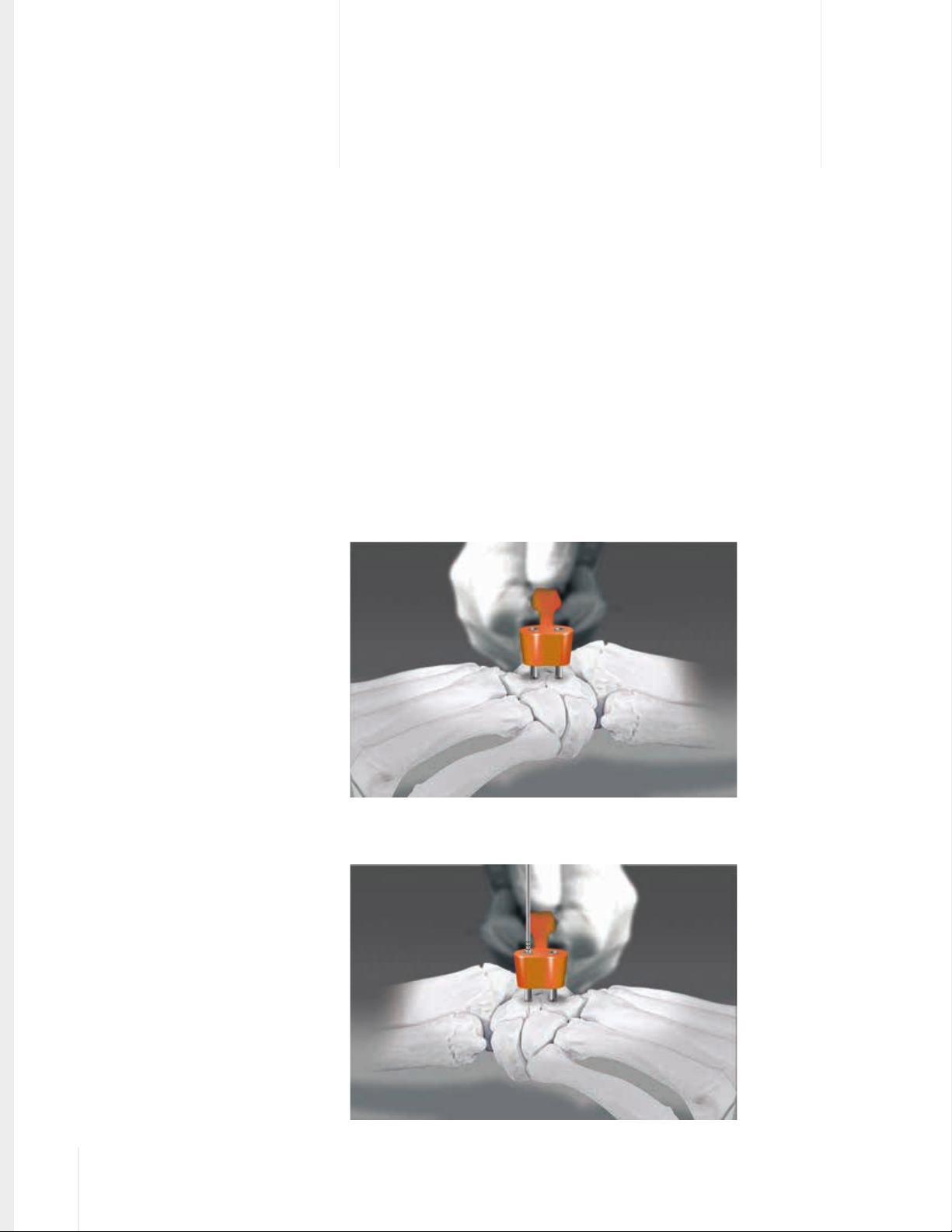
While maintaining desired reduction, place Reamer Guide across the fusion site
with both guides touching bone.
| Figure 1
2
chapter
Drill the first hole to the proper depth using the laser marked Reamer provided
in the Kit.
4 Chapter 1 Description of Chapter
Chapter 2 Surgical Technique
| Figure 2
| Figure 1
| Figure 2
Page 5
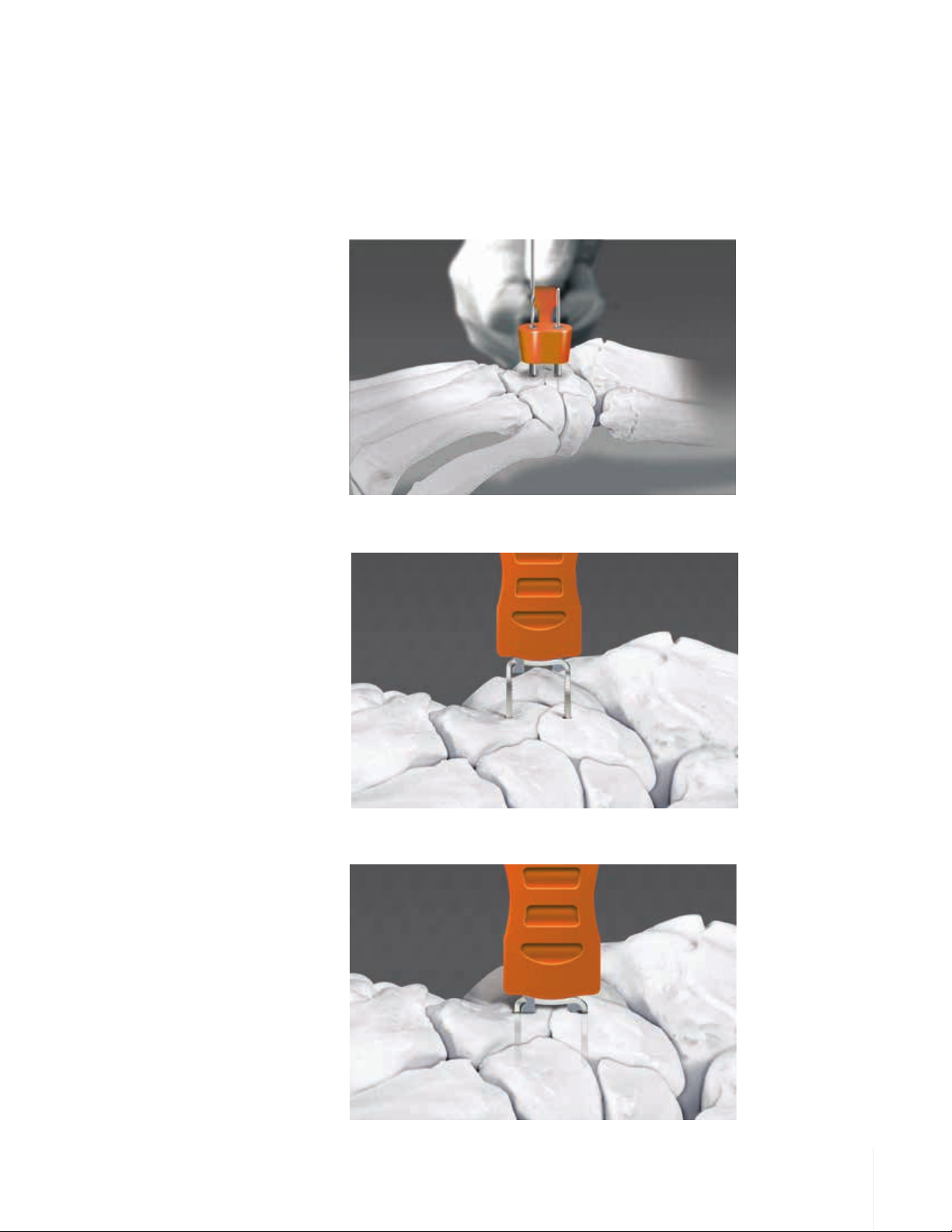
Insert a Locator Pin into the first hole to maintain proper reduction while the
second hole is drilled. Drill second hole to the proper depth using the laser
marked Reamer. Remove the Reamer, Locator Pin and Reamer Guide. Remove
the Inserter / Implant assembly from the sterile Kit.
| Figure 3
| Figure 3
While maintaining reduction, align and insert the tips of the FUSEFORCE® into
the drilled holes.
| Figure 4
| Figure 4
Tamp the FUSEFORCE® as flush to the bone as possible. Implant positioning
may be evaluated radiographically.
Chapter 2 Surgical Technique
| Figure 5
| Figure 5
5Chapter 1 Description of Chapter
Page 6
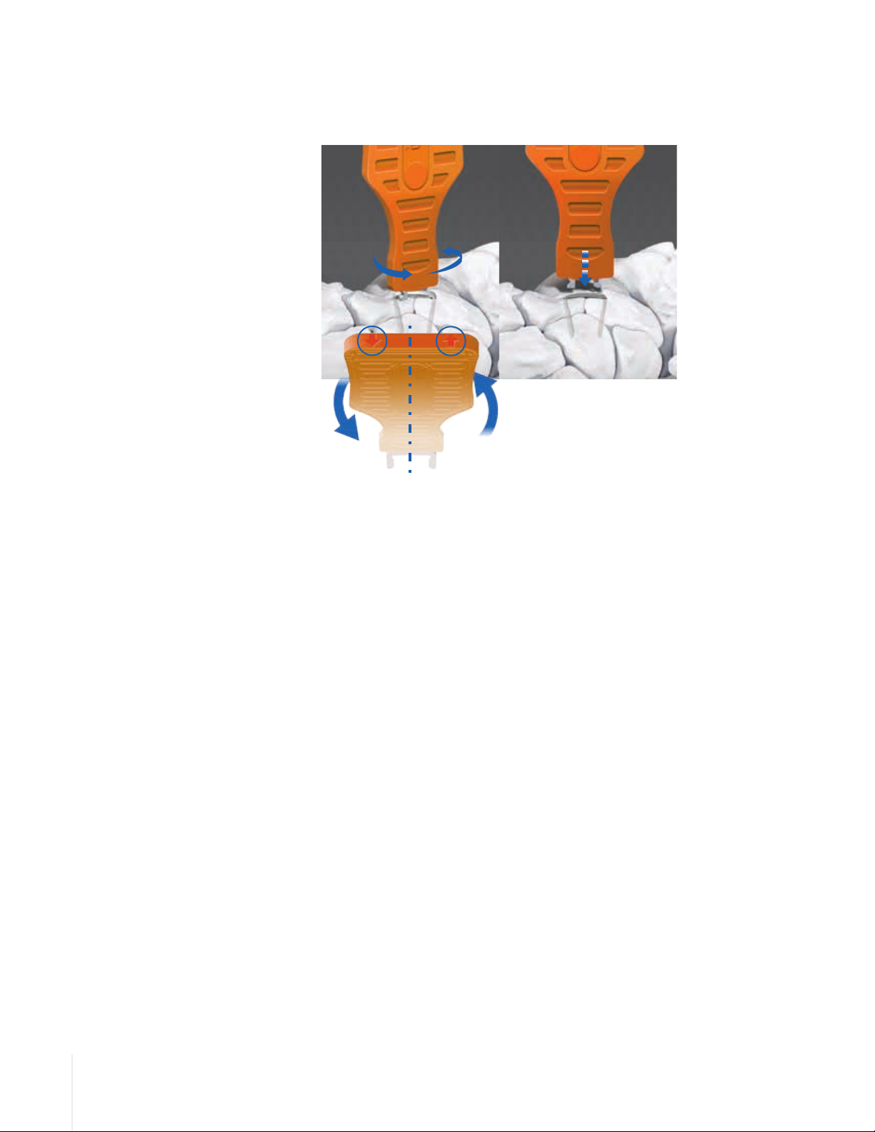
Twist the plastic Inserter counter- clockwise (as shown by arrows on top) to
release the Implant. Place the end of the Inserter on the implant and apply
pressure, manually or using a mallet, to fully seat the FUSEFORCE® Implant.
6 Chapter 1 Description of Chapter
Chapter 2 Surgical Technique
Page 7
Ordering
A
B
A
2mm
B
A
2mm
3mm
Information
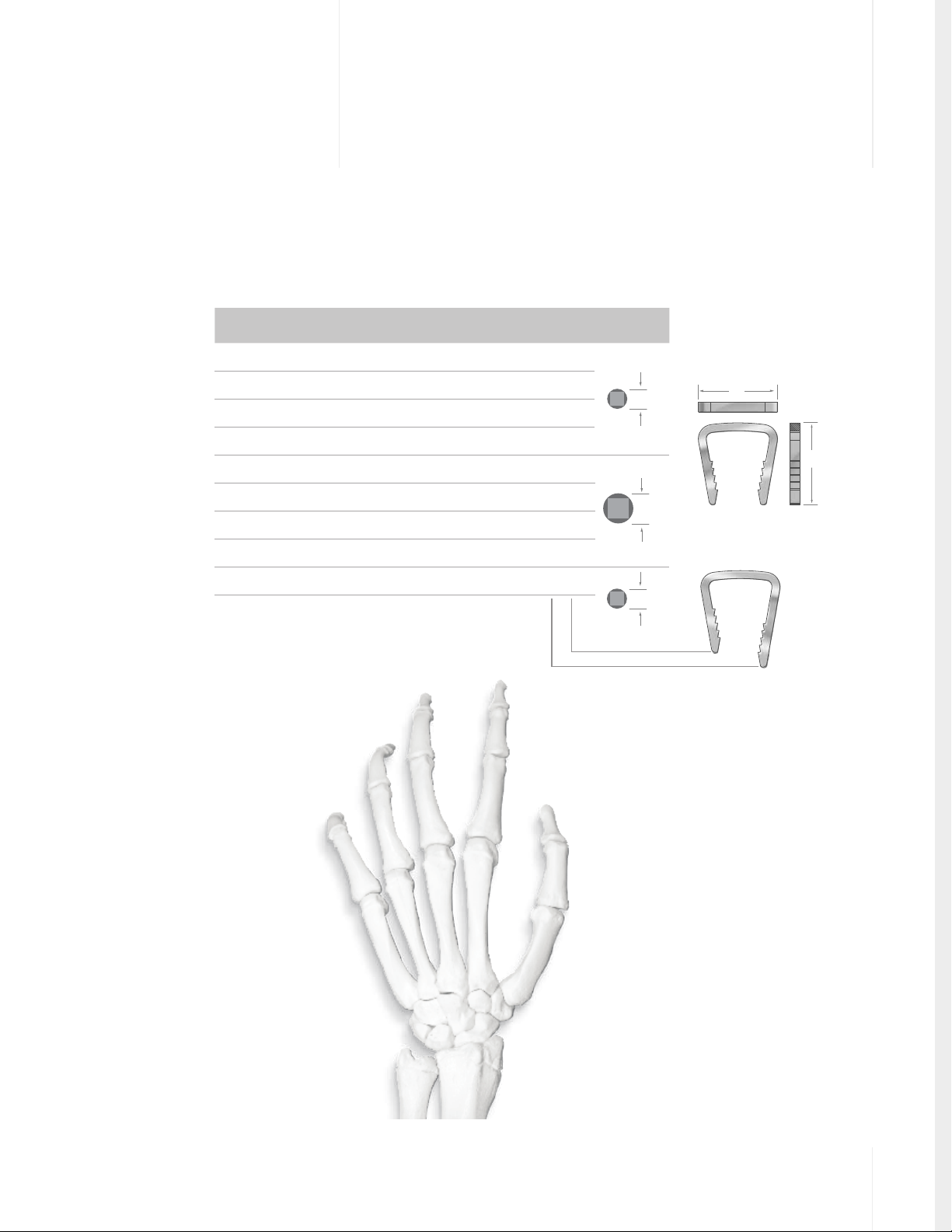
FUSEFORCE® Hand Fixation System
P/N ALT P/N*
FFNS0808 FFS-0808 FUSEFORCE® 8 8
FFNS1010 FFS-1010 FUSEFORCE® 10 10
FFNS1012 FFS-1012 FUSEFORCE® 10 12
FFNS1212 FFS-1212 FUSEFORCE® 12 12
FFNS1515 FFS-1515 FUSEFORCE® 15 15
FFNS1816 FFS-1816 FUSEFORCE® 18 16
FFNS2020 FFS-2020 FUSEFORCE® 20 20
FFNS2522 FFS-2522 FUSEFORCE® 25 22
FFNS101513 FFS-101513 FUSEFORCE® 10 15/13
Description Bridge
Width A
Leg
Length B
Reamer
Size
2mm
3mm
2mm
APPENDIX
APPENDIX A
A
B
*ALT PN is the Solana part number
CROSSCHECK® Plating System
FUSEFORCE® Ordering Information
7
Page 8

Wright Medical Technology, Inc.
1023 Cherry Road
Memphis, TN 38117
800 238 7117
901 867 9971
www.wmt.com
Wright Medical EMEA
Atlas Arena, Australia Building
Hoogoorddreef 7
1101 BA Amsterdam
the Netherlands
011 31 20 565 9060
Wright Medical UK Ltd.
Unit 1, Campus Five
Letchworth Garden City
Hertfordshire SG6 2JF
United Kingdom
011 44 (0)845 833 4435
™Trademarks and ®Registered marks of
Wright Medical Technology, Inc.
©2015 Wright Medical Technology, Inc.
All Rights Reserved.
011395B_19-Aug-2015
 Loading...