

Page 1
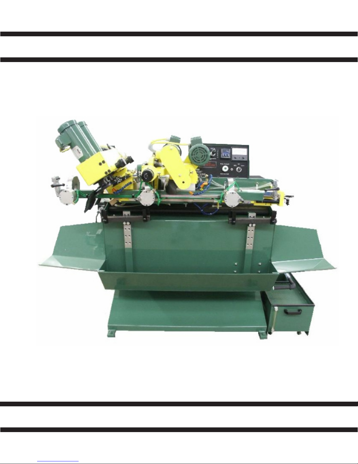
DUAL SIDE GRINDER
W-1904-P
OPERATORS MANUAL
MADE IN THE U.S.A.
3-01-06
Page 2

W-1904-P QUAD DUAL SIDE GRINDER
Contents
LIMITED WARRANTY ........................................................................................................... 2
GENERAL SAFETY RULES.................................................................................................. 3
SPECIFICATIONS ................................................................................................................. 4
OPTIONS .............................................................................................................................. 5
COMMON REPLACEMENT PARTS ..................................................................................... 5
PRE SET UP ......................................................................................................................... 6
MAINTENANCE......................................................................................................................7
MACHINE CONTROLS ......................................................................................................... 8
LOADING SAW ................................................................................................................... 12
TOOTH GEOMETRY ........................................................................................................... 14
CONVERSION CHART ....................................................................................................... 16
ELECTRICAL SCHEMATIC ................................................................................................. 21
AIR SCHEMATC...................................................................................................................23
PARTS LIST ........................................................................................................................ 25
INDEX.................................................................................................................................. 67
1
Revised 1-2014
Page 3

W-1904-P QUAD DUAL SIDE GRINDER
LIMITED WARRANTY
This machine is warranted against defects in workmanship and materials under normal use and
proper maintenance, for one year after date of purchase from WRIGHT MACHINE TOOL CO.
Any part which is determined to be defective in material or workmanship and returned to WRIGHT
MACHINE TOOL CO., shipping costs prepaid will be repaired or replaced, at WRIGHT MACHINE
TOOL CO. option.
WRIGHT MACHINE TOOL CO., INC. PHONE (541) 942-3712
365 Palmer Avenue FAX (541) 942-0730
Cottage Grove, Oregon 97424
2
Revised 1-2014
Page 4

3
W-1904-P QUAD DUAL SIDE GRINDER
GENERAL SAFETY RULES
Failure to follow the safety rules and other basic safety precautions, may result in serious
injury.
Always use eye protection: When operating this machine, eye protection should be worn. Grind-
ing particles and the possibility of wheel breakage make eye protection necessary. Also face or
dust mask if operation is dusty. Use adequate ventilation.
Use ear protection: If operation is creating excessive noise.
Disconnect power: To machine when NOT in use.
Keep Clear: Of grinding wheels and pinch points when machine is running.
Don’t over reach: Keep proper footing and balance at all times.
Saws are sharp: Wear appropriate personal protective equipment when handling saw blades.
Mounting of wheels: Should only be done by persons with mechanical aptitude and good knowl-
edge of mounting, care, and inspection of grinding wheels. Wheels must be rated for the RPM of
the machine.
Dress properly: Do not wear loose clothing or jewelry. Nonskid foot wear is recommended. Wear
protective hair covering to contain long hair.
Avoid dangerous environments: Don’t use in wet location. Keep work area well lit. Do not use
this machine in the presence of flammable liquid or gasses.
Keep children away: Do not let VISITORS contact this machine.
Keep work area clean: Cluttered areas invite accidents.
All electrical covers: Must be in place before applying electrical power to this machine. Electri-
cal service must be locked out prior to removing any electrical covers on machine guards. Access
to electrical components must be restricted to trained personnel only to avoid possible electrical
shock.
Voltage greater: Than specified on name plate can result in serious injury to user.
Never stand on this machine: Serious injury could occur if the machine tipped or if the grinding
wheel is accidently contacted.
Follow safety precautions: For the wheels, coolant and material being ground. This information
is available on the Safety Data sheet for each of these products.
Revised 1-2014
Page 5

W-1904-P QUAD DUAL SIDE GRINDER
SPECIFICATIONS
The W-1904-P “QUAD” is designed to Side Grind Band Saws. A Roughing Station sizes
the tooth to approximate dimension using two 5" 11V9 Cup Wheels, at the same time
the Finish Station grinds the second tooth to the exact dimension using two 5" C. B.
N. Grinding Wheels.
STANDARD VOLTAGE: 440 Volt, 3 Phase, 50/60 HZ
OPTIONAL VOLTAGE: As Requested
4
SHIPPING WEIGHT: 2,300 lbs
CRATE SIZE: L 83" X W 48" X H 60"
AIR REQUIREMENTS: 2 CFM at 80 psi
STANDARD SAW SIZE: 6" to 16"
OPTIONAL SAW SIZE: Down to 2"
SPINDLE MOTORS: (4) 1hp 3450 RPM Motors TEFC
Revised 1-2014
Page 6

W-1904-P QUAD DUAL SIDE GRINDER
OPTIONS
Totalizer Counter W-70
Double Cuts Saw Carrier for Machine: W-1550
Short Band Saw Support Assembly: W-2083
Narrow Band Saw Carrier 2" to 6": W-2190
Sliver Tooth Saw Carrier (4 Required): W-2231-1
5
Stands: W-2259 Back Feed
W-2260 Back Stands
W-2262 Guide Stands
Double Cuts Saw Carrier for Back Stands: W-2265
S G Grinding Wheel (Rough Head) V-45 (2 Req.)
Borazon Grinding Wheel (Finish Head) B-45 (2 Req.)
COMMON REPLACEMENT PARTS
Coolant Nozzle W-1294
Feed Finger Assy W-2186-1
Revised 1-2014
Page 7

W-1904-P QUAD DUAL SIDE GRINDER
PRE SET UP
COOLANT
Coolant capacity is 7 to 10 gallons. A rust inhibiting grinding coolant MUST be used or severe
rust damage to machine can result. Mix coolant according to manufacturer’s instructions.
Coolant pump plugs into female receptacle on back door of the machine.
RUST DAMAGE IS NOT COVERED BY THE WARRANTY
MOUNTING GRINDING WHEELS
All grinding wheels must be rated for the RPM of this machine. Wheels exposed
to higher than rated RPM are dangerous.
Mounting of the grinding wheel should only be done by persons with mechanical aptitude
and good knowledge of mounting, care, and inspection of grinding wheels.
6
STYLE OF GRINDING WHEELS
ROUGHING HEAD
V-45 5" X 1-3/4" X 1-1/4" 11V9 2 Required
Cup Wheel
FINISH HEAD
B-45 5" X 1-3/4" X 1-1/4" Borazon 2 Required
Cup Wheel
GRINDING WHEELS MUST BE RATED FOR 5000 RPM OR THE RPM OF YOUR
MACHINE.
NOTE: Power must be disconnected to machine when changing Grinding Wheels.
To change Grinding Wheels move head to full open position. With a 3/16 Allen wrench,
loosen wheel retainer bolt located through the 1/2" hole in the belt cover. The wheel retainer
bolt is standard right hand thread.
Revised 1-2014
Page 8

W-1904-P QUAD DUAL SIDE GRINDER
The useful life of this machine can be dramatically extended if the following
rules of operation are followed.
1. Clean the machine regularly.
2. A good rust inhibiting coolant must be used in the correct ratio. Too weak a mix will
cause rust problems and too thick will damage the paint and load the Diamond wheels.
3. Do not clean the machine with high pressure air or water. This can blow grit into the
internal parts of the machine and cause rusting problems which is not covered by warranty.
MAINTENANCE
DAILY 1. Check coolant level and filter.
2. Clean exterior of machine.
3. Check hydraulic oil level. (periphery grinder)
7
WEEKLY 1. Check coolant tank for carbide buildup.
2. Replace coolant filters.
MONTHLY 1. Grease index linear bearing.
or 100,000 CYCLES 2. Inspect feed finger for wear.
3. Inspect clamp jaws for wear.
4. Inspect roller hold down bearings.
EVERY 6 MONTHS 1. Inspect spindle drive belt.
or 500,000 CYCLES 2. Clean spindle motor fan.
3. Remove stainless splash guards and clean completely.
4. Inspect index system linear slide bearing assembly for
excessive clearance.
EVERY 24 MONTHS 1. Replace spindle drive belt and inspect pulleys.
or 1,000,000 CYCLES 2. Inspect pulleys for wear.
Revised 1-2014
Page 9
W-1904-P QUAD DUAL SIDE GRINDER
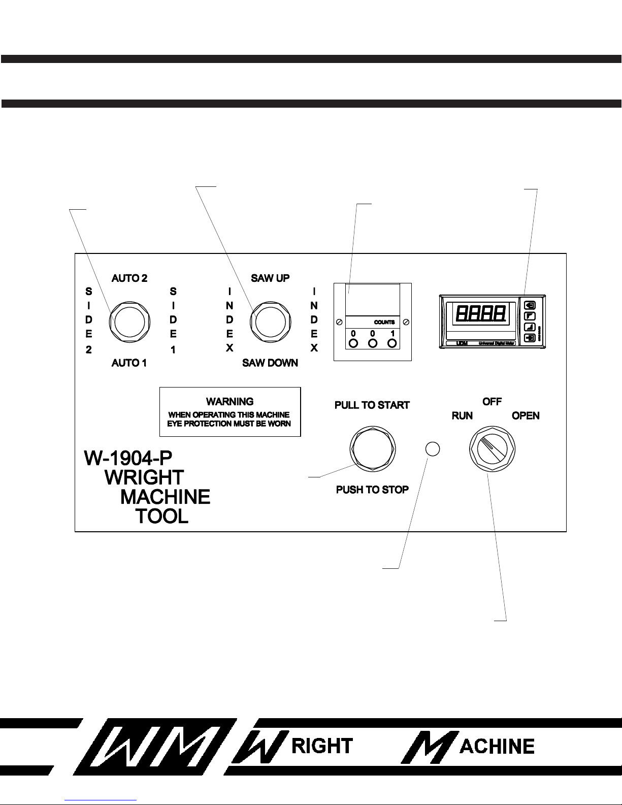
CONTROL PANEL
8
A
W-735-TW
B
W-735-TW
E
W-194
C
W-195
D
W-1427-1
F
W-1011
G
W-1004
Revised 1-2014
Page 10
9
W-1904-P QUAD DUAL SIDE GRINDER
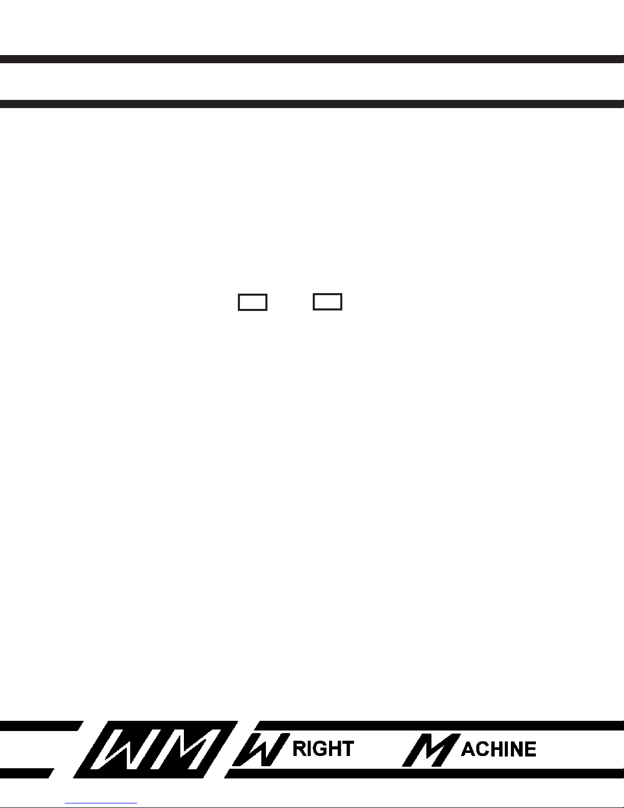
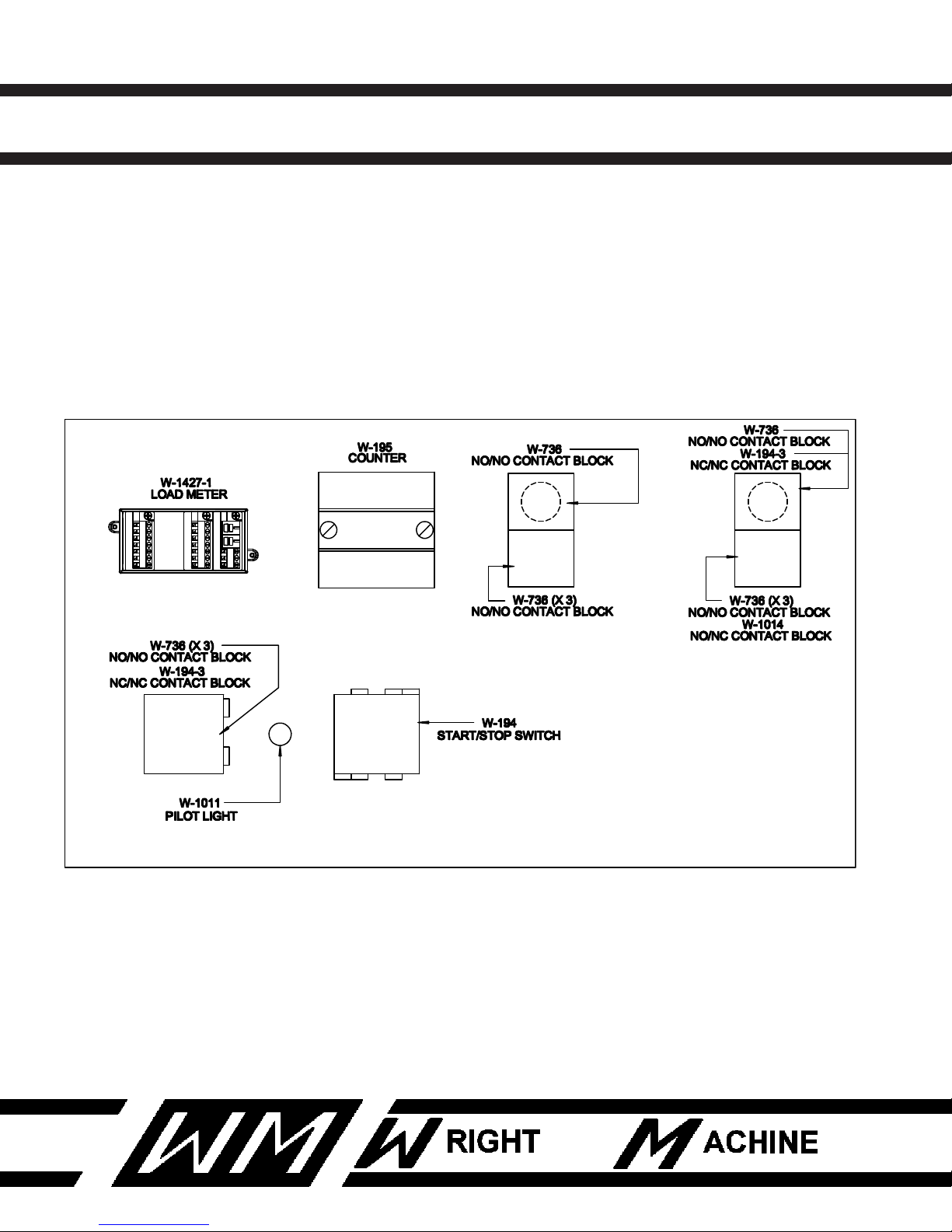
CONTROL PANEL
A. Control Joy Switch has 5 positions. Left for side #2 (Manual Finish Head In only), right for
side #1 (Manual Rough In only), down for Automatic #1 (Rough Grind only) up is for Automatic
#2 (Rough and Finish Grind only.) Machine must be running for these controls to work.
B. Saw Up / Saw Down only function when saw clamp is open. Index Forward / Reverse
only function when saw clamp is closed and machine is not running.
C. Tooth Counter only counts in the Automatic #2 position.
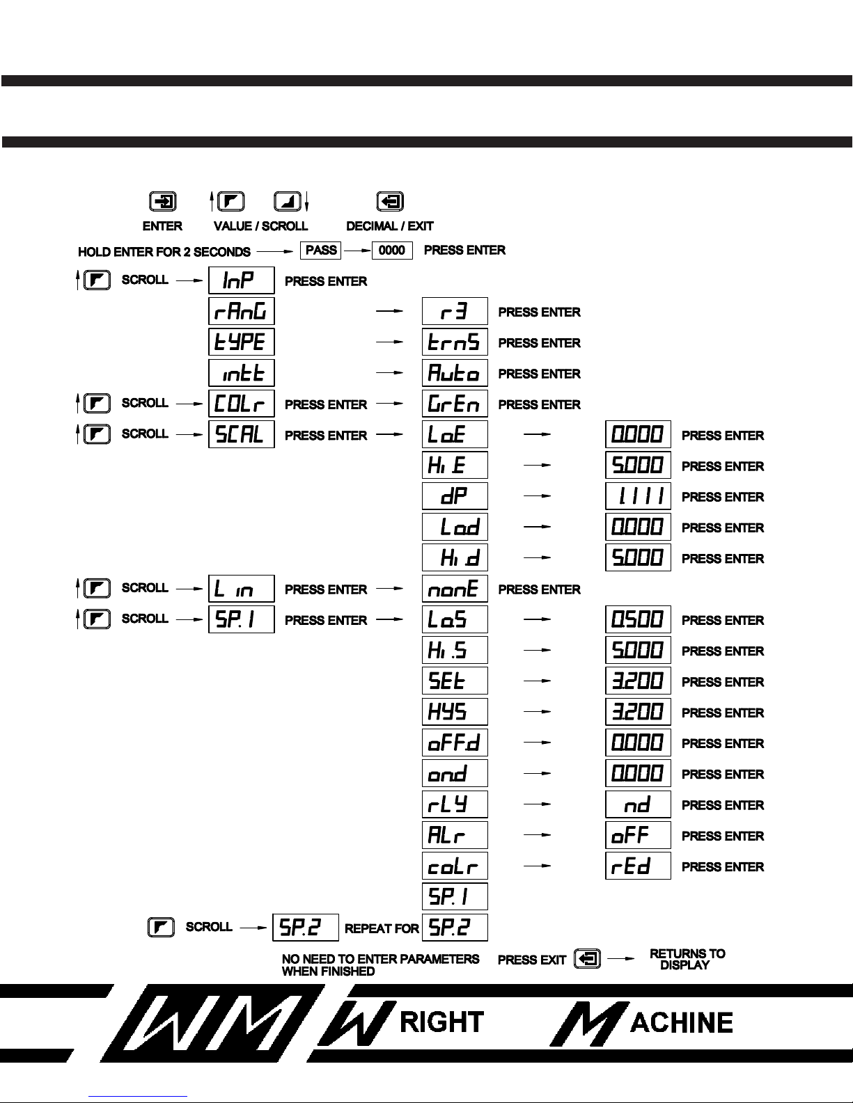
D. The Load Meter monitors the power required to grind with the periphery Heads. The Load
Meter is set by accessing the SET and the HYS screens.
The meter controls the set point which is a nominal amp draw with no grind load. The hystersis
is what established the amp draw during the grind, which suspends forward grind motion if
the Finish Head hits a tooth that is wider than expecxted, this load meter will slow the speed
as necessary to reduce the chance of wheel or saw damage.
E. Pull to start - Push to stop.
F. Indicator light shows power to machine.
G. Open position - Opens saw clamp jaws. Run position - Closes clamp jaws and allows the
machine to be started. When machine is not in use turn to Off position.
Revised 1-2014
Page 11
W-1904-P QUAD DUAL SIDE GRINDER
LOAD METER
10
Revised 1-2014
Page 12
W-1904-P QUAD DUAL SIDE GRINDER
CONTROL PANEL BACKSIDE
11
Revised 1-2014
Page 13
W-1904-P QUAD DUAL SIDE GRINDER
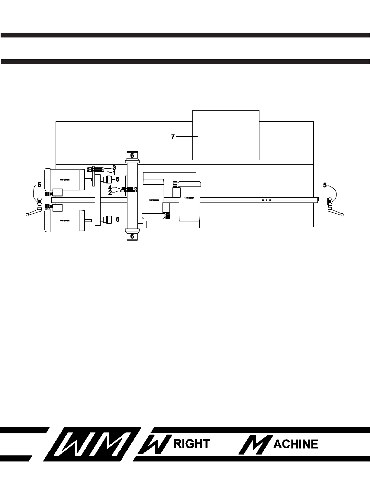
MACHINE CONTROLS
12
1. Depth of grind Finish Head.
2. Depth of grind Roughing Head.
3. Grind speed Finish Head.
4. Grind speed Roughing Head.
5. Band Saw hold downs (2).
6. In-Feed knobs (4).
7. Control console.
Revised 1-2014
Page 14
W-1904-P QUAD DUAL SIDE GRINDER
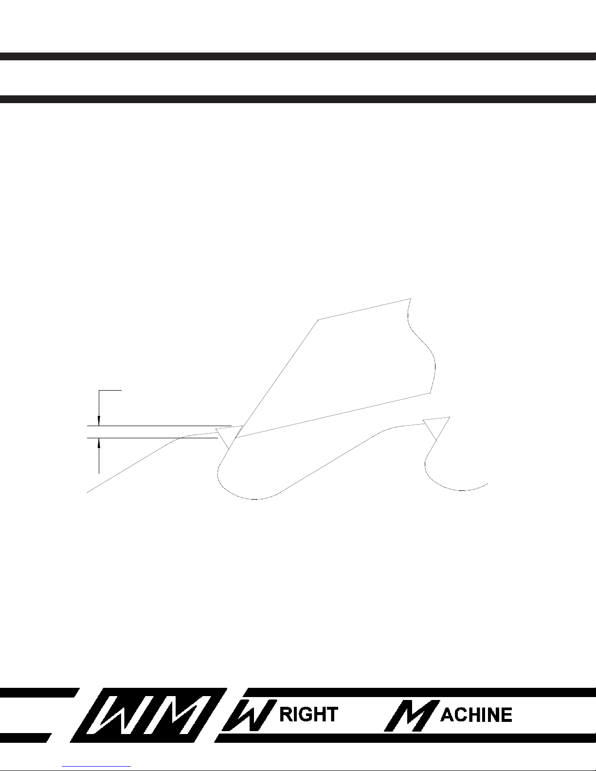
1/8"
LOADING SAW
1. Turn Switch (G) to Open. Move Saw carrier Down by moving Switch (B) to Saw Down.
2. Place saw in carrier track. Move Switch (B) to Saw Up. As saw is traveling up through
the Clamp Jaws, make certain that the Index Fingers are over a gullet. Otherwise the fingers
and saw tooth may be damaged.
HANDS MUST BE KEPT CLEAR OF PINCH POINTS DURING THIS OPERATION
3. The band saw is in the proper position when the tooth is 1/8" above the Index Finger.
13
NOTE: The more accurate the height is set, less variation in Kerf will be experienced. If the tooth is placed higher a wider Kerf will occur. If lower, a narrower Kerf
will occur.
Revised 1-2014
Page 15

W-1904-P QUAD DUAL SIDE GRINDER
LOADING SAW
SET UP (CONTINUED)
4. Tighten Band Saw Hold Down at each end of the Saw Clamp Bar. If too tight the index will
not be able to slide back, and if too loose the band saw will lift up when indexing.
5. After making sure the Index Finger is in the gullet, turn Switch (G) to Run. This will close
the Clamp Jaws. Move Joy Switch (B) to the left until a tooth passes the Index Finger. Then
allow Joy Switch (B) to return to center position.
6. At this time a saw tooth should be against the Index Fingers. If the index stroke is insufficient, adjust as shown on page 10
14
7. Set Tooth Counter (C) on the number of teeth to be ground.
8. Place Joy Switch (A) in center position, pull Start button.
9. After coolant flow is on tip, place Joy Switch (A) into Automatic #1.
10. The grinding head will travel down and grind a tooth. Set speed and stroke as necessary.
11. Adjust In-Feed knobs as necessary on the grinding head to achieve desired finish kerf
width. Set speed and stroke as necessary.
Revised 1-2014
Page 16
W-1904-P QUAD DUAL SIDE GRINDER
TOOTH GEOMETRY
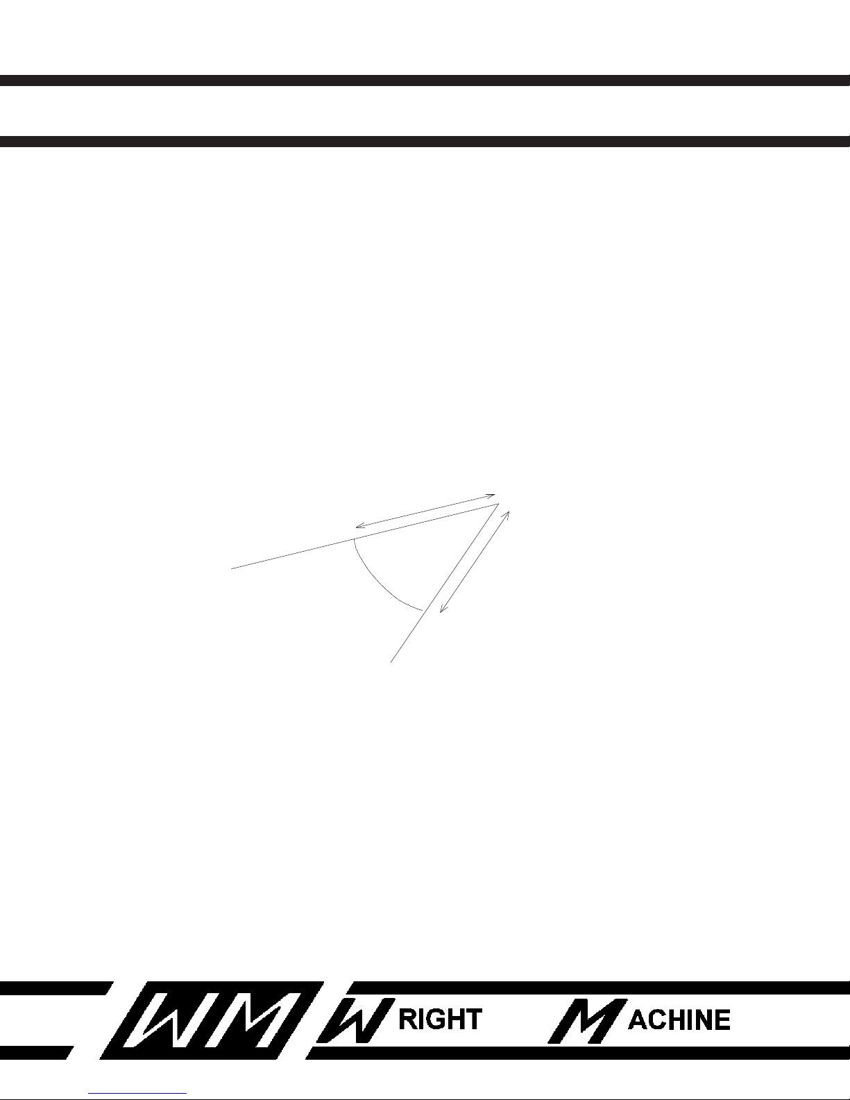
The W-1904 is set at what we consider AVERAGE tooth angles when it leaves
our factory.
FINISH HEAD
30 Degree Hook - 8 Degree Back 3 Degree Tangential 3 Degree Radial
ROUGHING HEAD
30 Degree Hook 0 Degree Tangental 1 Degree Radial
15
TANGENTAL
RADIAL
NOTE: The Roughing Head must be set on 0 degree tangental.
If different angles are desired, adjust as follows.
RADIAL ANGLE
Loosen Radial Lock Bolts, move In-Feed handle up or down as necessary to
set desired radial angle. Radial scale reads in degrees.
TANGENTAL ANGLE
Loosen Tangental Lock Bolts and move Spindle Housing as necessary to set
desired tangental angle. Tangental scale reads in degrees.
Revised 1-2014
Page 17
W-1904-P QUAD DUAL SIDE GRINDER
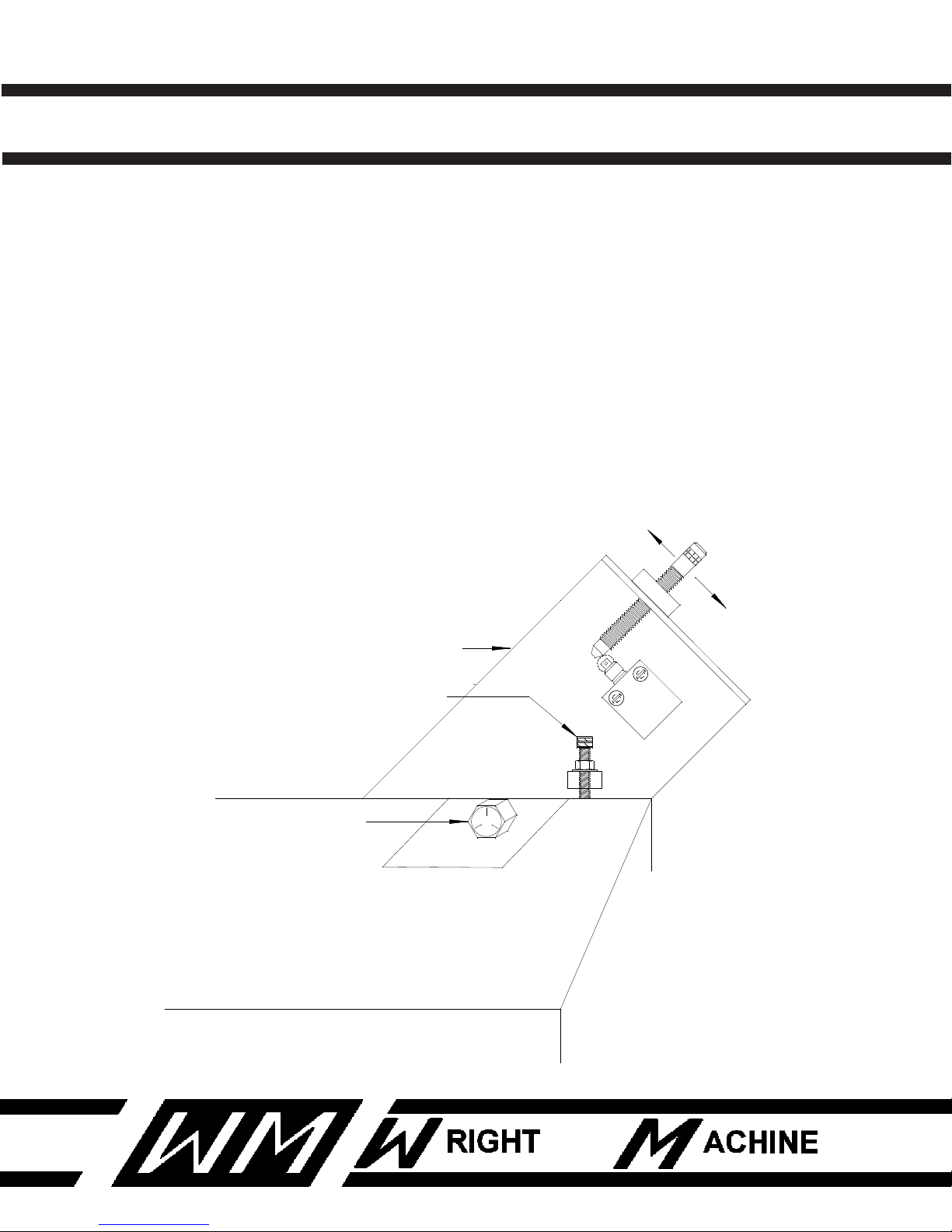
GRINDING HEAD
HEAD ADJUSTMENT BOLT
HEAD ATTATCHMENT BOLT
LESS RADIAL
MORE TANGENTAL
MORE RADIAL
LESS TANGENTAL
TOOTH GEOMETRY
INCREASE RADIAL ANGLE VS TANGENTAL ANGLE
Loosen bolts that attach head to base and rotate head using adjustment bolt.
INCREASE RADIAL AND TANGENTAL ANGLE
Loosen feed finger tower bolts and move tower to the right to increase both
angles. Move tower to the left to decrease angles. Rotating head clockwise
increases radial angle and decreases tangental angle. Rotating head counterclockwise increases tangental angle and decreases radial angle.
16
Revised 1-2014
Page 18
W-1904-P QUAD DUAL SIDE GRINDER
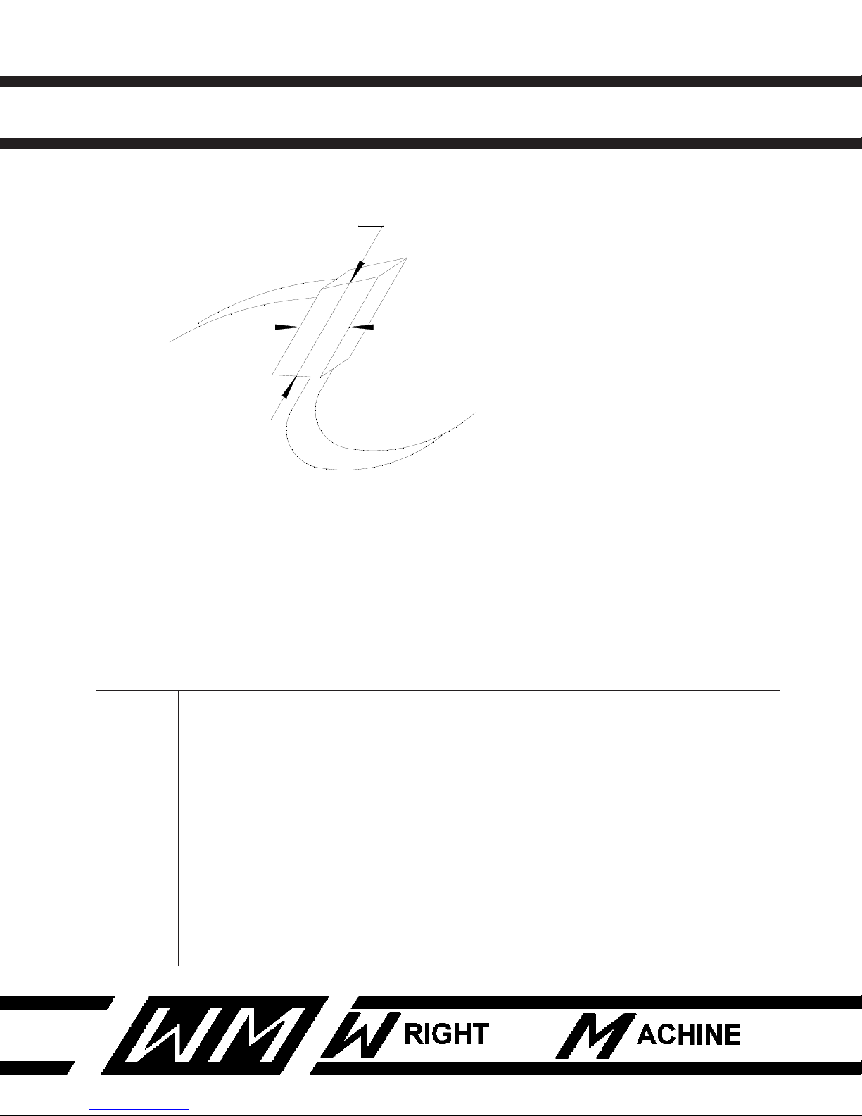
RADIAL ANGLE
TOP TO BOTTOM
TANGENTAL ANGLE
FRONT TO BACK
17
CONVERSION CHART
DEGREES OF ANGLE CONVERTED TO DROP OFF IN THOUSANDTHS X DISTANCE.
To convert degrees to thousandths, select degrees required on line (A). Example:
3.5 degrees. On line (B) select length of measurement. Example: .375 for a 3/8 tip.
Where 3.5 degrees and .375 intersect is drop off in thousandths of an inch.
Line (A) .5 1 1.5 2 2.5 3 3.5 4 4.5 5 5.5 6
.125 1 2 3 4 5 6 7 8 9 10 11 12
.250 2 4 7 9 11 13 15 18 20 22 24 26
.312 3 5 8 11 14 16 19 22 25 27 30 33
.375 3 7 10 13 16 20 23 26 30 33 36 39
.437 4 8 11 15 19 23 27 30 34 38 42 46
.500 4 9 13 17 22 26 31 35 39 44 48 52
Line (B)
Revised 1-2014
Page 19
W-1904-P QUAD DUAL SIDE GRINDER
21
R
N2
M2
120V
14A
4
19
16
15
17
20
18
DOWN
C NC
C NC
UP
N1
CLOSED IN
OPEN
SAW CLAMP
T2
T1
S1
S3
SAW
LIFT
BLU
REDBLK
S2
T3
M1
CLOSED
IN RUN
PULL TO START
PUSH TO STOP
10
24
25
O
P
6 8 4 5
95 96
95 96
COUNTER
TOOTH
COUNT
FINISH
MS2
ROUGH
MS1
1
2
A1
A2
A1 A2
10 14
K3
L4
COUNTER
MS CR4
2 10
X
4
27 11
SAW CLAMP
FULL PRESSURE
G
WATER
PUMP
3
MS
Q1
CRB
CRA
11
12 4
3
14
13
CRA
14
13
CRB
10 2
9 1
CRA
MS2 OL
MS1 OL
DRAG OPEN
CRB
ORG
M3
OPEN IN RUN
PURPLE
YELLOW
BLUE
3 4
3 4
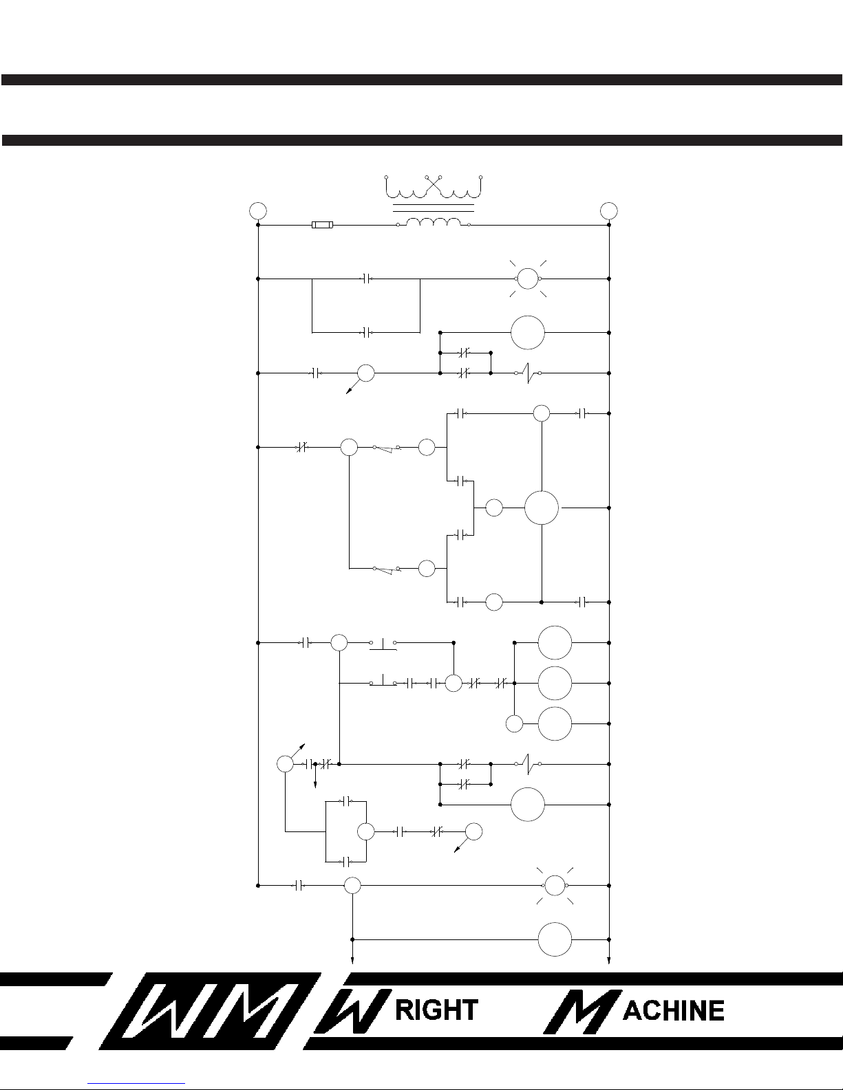
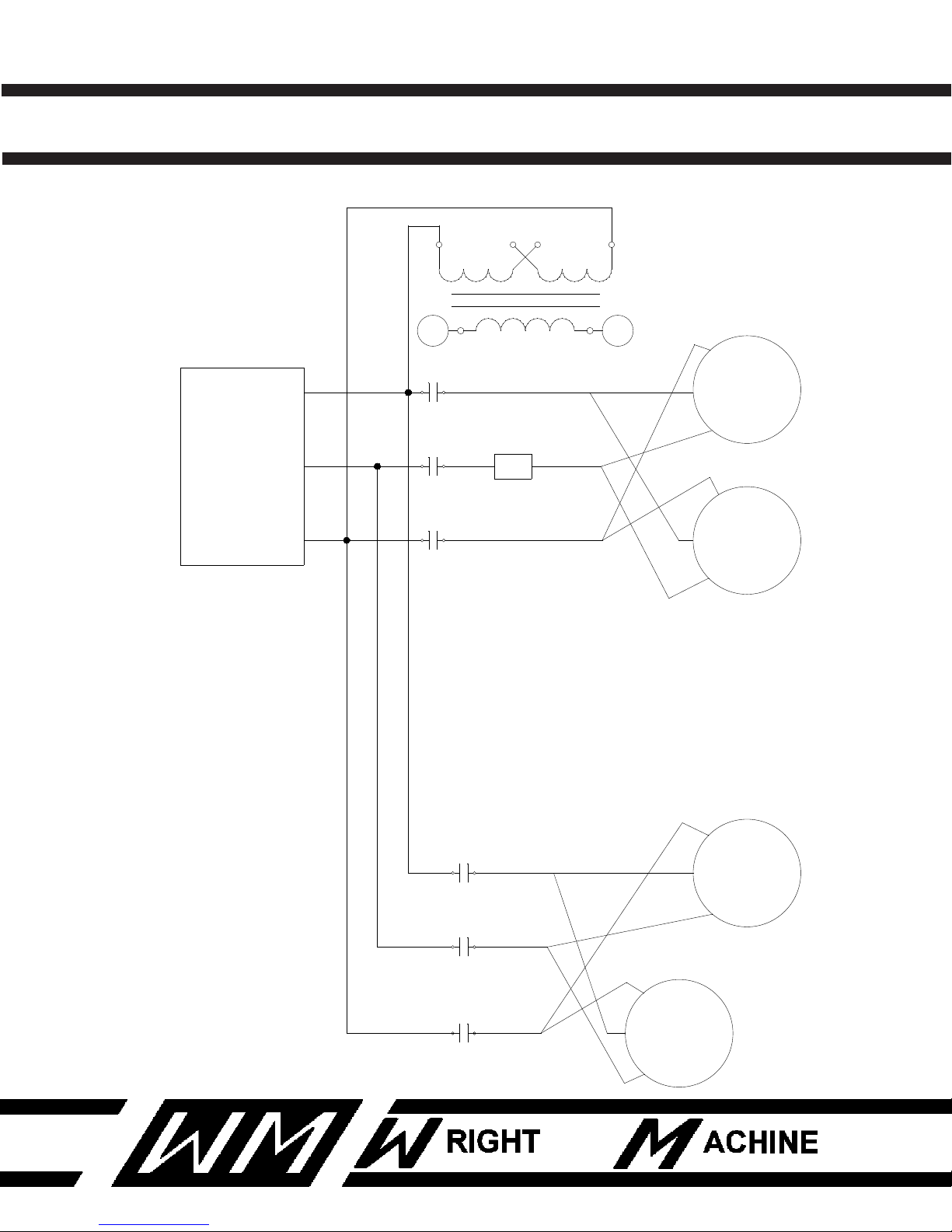
ELECTRICAL SCHEMATIC
18
Revised 1-2014
Page 20
W-1904-P QUAD DUAL SIDE GRINDER
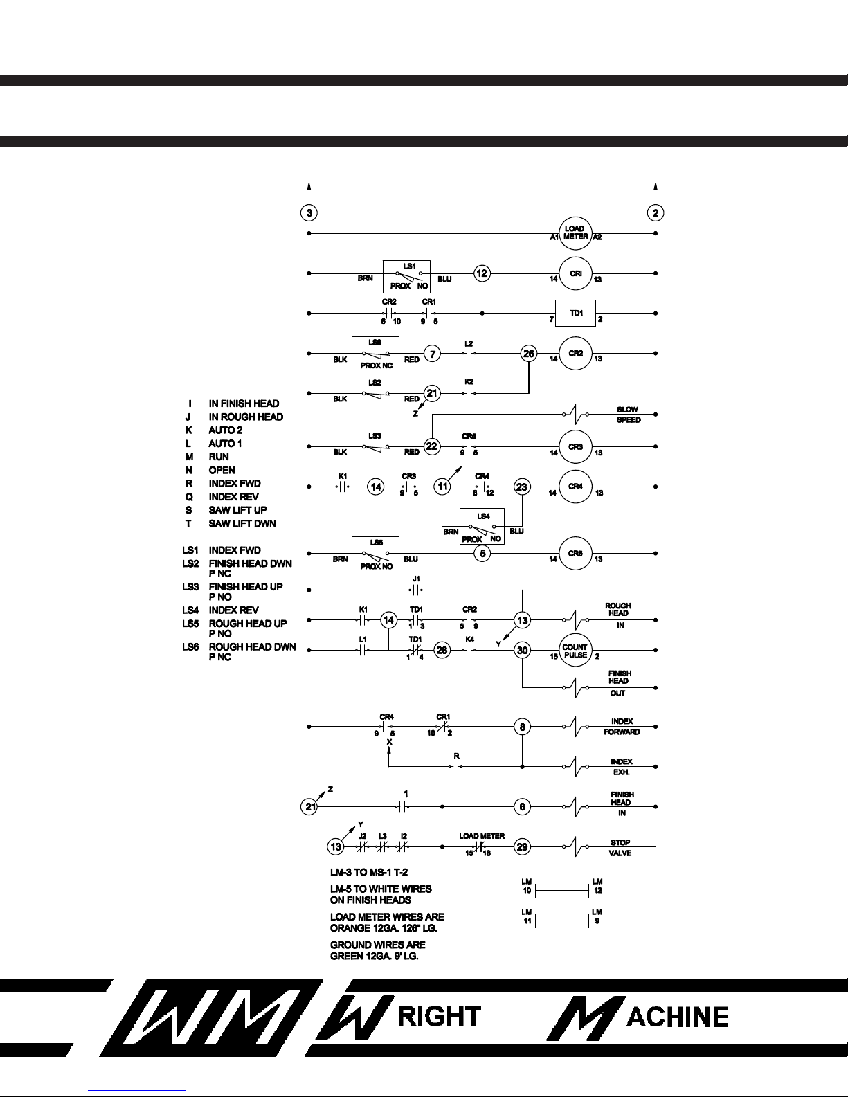
ELECTRICAL SCHEMATIC
19
Revised 1-2014
Page 21
W-1904-P QUAD DUAL SIDE GRINDER
110V
440V
1
2
440V
3 PH.
FINISH
MS1
L1 T1
L2 T2
L3 T3
L1
L2
L3
T1
T2
T3
ROUGH
MS 2
MTT
7,4
9,6
8,5
2
3
1
3
2
1
7,4
9,6
8,5
7,4
9,6
8,5
8,5
9,6
7,4
3
2
1
3
2
1
LM
1 2
ELECTRICAL SCHEMATIC
20
Revised 1-2014
Page 22
W-1904-P QUAD DUAL SIDE GRINDER
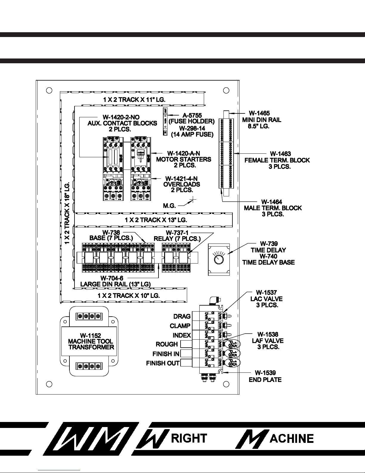
SUB PANEL ASSEMBLY
21
Revised 1-2014
Page 23

W-1904-P QUAD DUAL SIDE GRINDER
SUB PANEL ASSEMBLY
QTY PART NUMBER DESCRIPTION
1 A-5755 FUSE HOLDER
2 F-11 10-24 NUT
18 F-56 #10 SAE WASHER
18 F-333 10-24 X 3/8 SCREW
1 F-337 10-24 X 1-1/4 SCREW
2 F-345 8-32 X 3/8 SCREW
2 F-357 10-24 X 1-1/2 SCREW
1 W-298-14 14 AMP FUSE
1 W-2202-Q SHEET METAL PANEL
7 W-737-1 RELAY W/LIGHT
7 W-738 RELAY BASE
13" W-704-6 LARGE DIN RAIL
1 W-739 TIME DELAY
1 W-740 TIME DELAY BASE
1 W-1152 MACHINE TOOL TRANSFORMER
52" W-1446 1" X 2" SLA TRACK
2 W-1420-2-NO AUX. CONTACT BLOCK
2 W-1420-A-N MOTOR STARTER
2 W-1421-4-N OVERLOAD
3 W-1463 FEMALE TERMINAL BLOCKS
3 W-1464 MALE TERMINAL BLOCK
8.5" W-1465 MINI DIN RAIL
3 W-1537 LAC VALVES
2 W-1538 LAF VALVES
1 SET W-1539 END PLATE
22
Revised 1-2014
Page 24
W-1904-P QUAD DUAL SIDE GRINDER
DRAWING NUMBER
REVISED
DRAWN BYAPPROVED BYSCALE
DATE
WRIGHT MACHINE TOOL
REGULATOR
80 PSI
W-161
FILTER
(TRAP)
MUFFLER
W-1442
EXH.
DRAG
CLAMP NC GRN
NC GRN
IN
AIR
INDEX
ROUGH
6
W-1537
NC BLU
NO BLU
NO YEL
NC YEL
NO RED
ROUGH
HEAD CYL.
W-2209-1
40 PSI. REG.
INDEX REV.
W-68
CLAMP CYL.
3 EA.
W-2236
IN
INDEX REV.
QUICK EXH.
W-162
OUT
INDEX CYL.
W-1402-M
8
NONE DGR
SHEET 1 OF 1
1
DATE
SYMBOL
APPD.
BY
CHANGE(S) MADE...
BY
DRAWN
1
DATE
SYMBOL
APPD.
BY
CHANGE(S) MADE...
CHANGE(S) MADE...
0-00-00LP
BY
DRAWN
NO RED
OUT
IN
W-465
FF
FREE FLOW
0 19
OIL POT
15
FINISH OUT
COUNTER
13
8
10
4
W1904W1904-PAIR
W-1904-P
06-03-03
SIDE FEED
CYLINDER
W-2209
W-465
FF
FREE FLOW
0 19
SLOW
FEED
SIDE
STOP VALVE
W-1009
STOP
VALVE
OUT
IN
#7
#9
FINISH IN
CLR
BLK
RED
W-1904-P AIR DIAGRAM
W-1538
W-1537
BC DP
MIRRORED FLOW VALVES
7-08-03
1
1
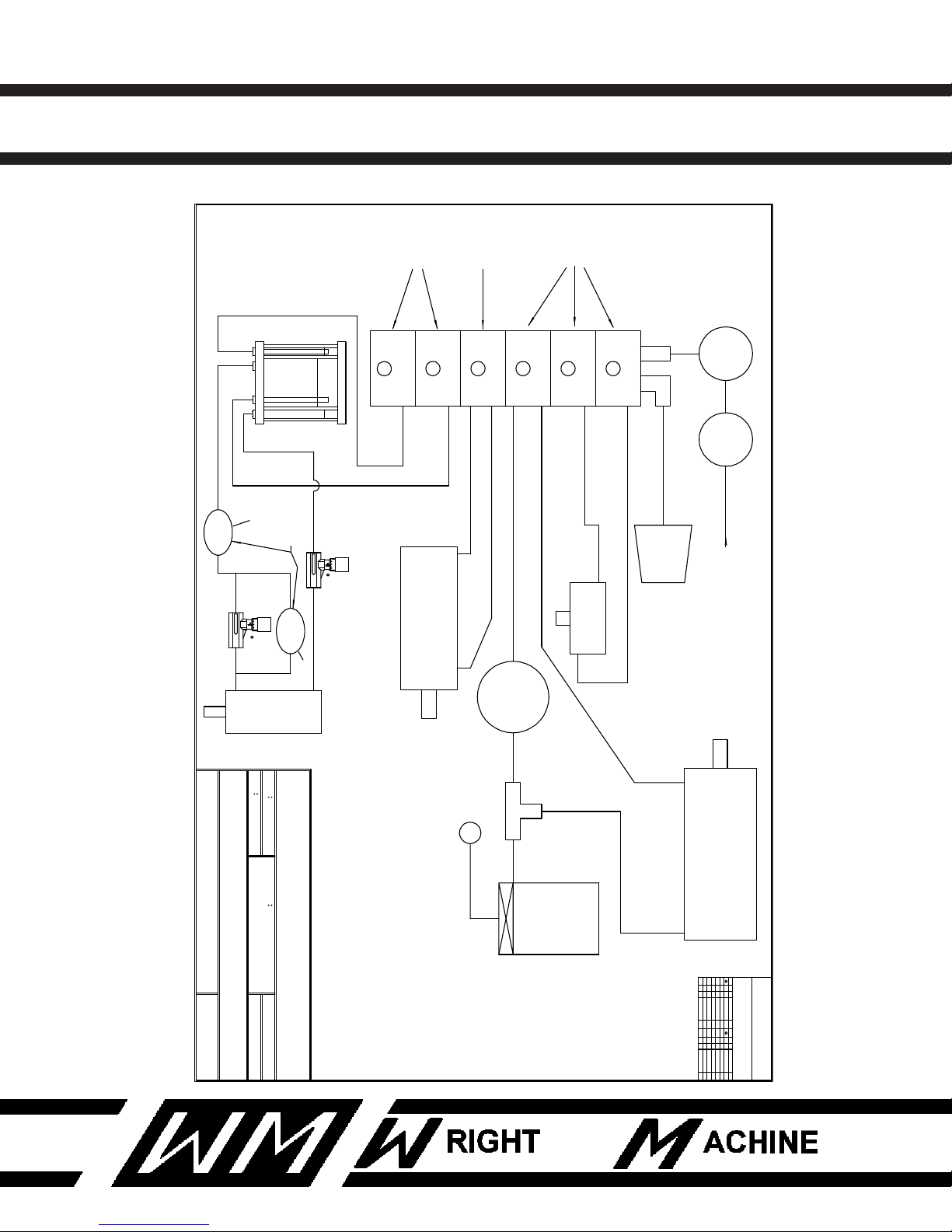
AIR SCHEMATIC
23
Revised 1-2014
Page 25
W-1904-P QUAD DUAL SIDE GRINDER
24
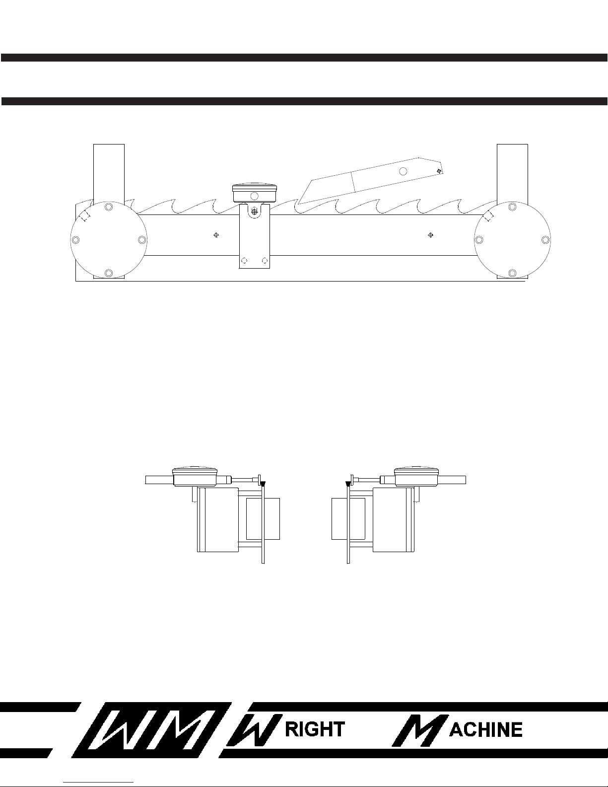
NOTE: USE SIDE DIAL INDICATOR WITH CLAMP JAWS
CLOSED.
THIS WILL INSURE PROPER MEASUREMENT.
Revised 1-2014
Page 26

W-1904-P QUAD DUAL SIDE GRINDER
PARTS LIST
This parts list is broken down into various areas within the machine.
Each of the following areas have part numbers that start on the first page with
an assembly view on the following page.
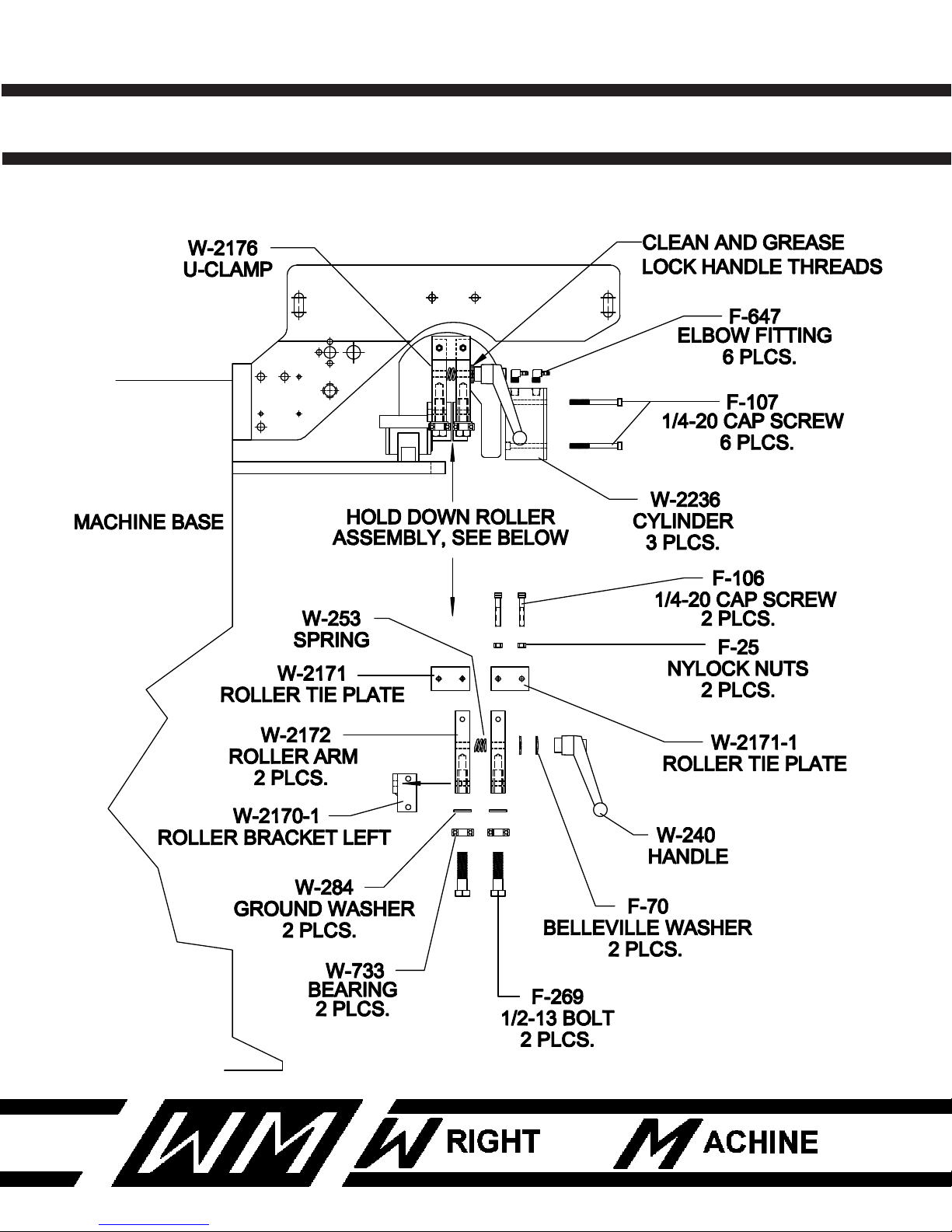
LEFT END OF BASE (OUTSIDE)
QTY PART NUMBER DESCRIPTION
2 F-25 NYLOCK NUTS
2 F-70 BELLEVILLE WASHER
2 F-106 1/4-20 SOCKET HEAD CAP SCREW
6 F-107 1/4-20 SOCKET HEAD CAP SCREW
2 F-269 1/2-13 BOLT
6 F-647 ELBOW FITTING
1 W-240 HANDLE
1 W-253 COMPRESSION SPRING
2 W-284 GROUND WASHER
2 W-733 BEARING
1 W-2170-1 ROLLER BRACKET LEFT
1 W-2171 ROLLER TIE PLATE
1 W-2171-1 ROLLER TIE PLATE
2 W-2172 ROLLER ARM
1 W-2176 U-CLAMP
3 W-2236 AIR CYLINDER
25
Revised 1-2014
Page 27
W-1904-P QUAD DUAL SIDE GRINDER
LEFT END OF BASE (OUTSIDE)
26
Revised 1-2014
Page 28

W-1904-P QUAD DUAL SIDE GRINDER
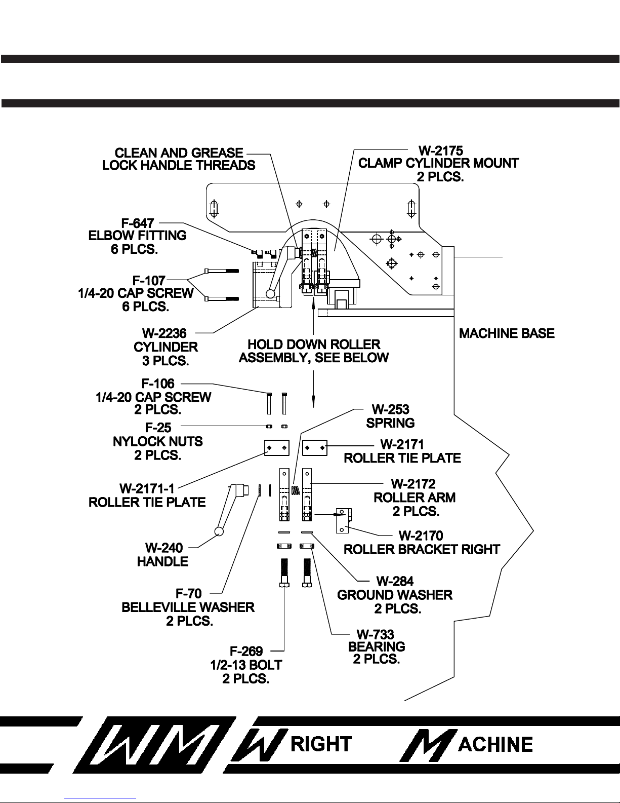
RIGHT END OF BASE (OUTSIDE)
QTY PART NUMBER DESCRIPTION
2 F-25 NYLOCK NUTS
2 F-70 BELLEVILLE WASHER
2 F-106 1/4-20 SOCKET HEAD CAP SCREW
6 F-107 1/4-20 SOCKET HEAD CAP SCREW
2 F-269 1/2-13 BOLT
6 F-647 ELBOW FITTING
1 W-240 HANDLE
1 W-253 COMPRESSION SPRING
2 W-284 GROUND WASHER
2 W-733 BEARING
1 W-2170 ROLLER BRACKET RIGHT
1 W-2171 ROLLER TIE PLATE
1 W-2171-1 ROLLER TIE PLATE
2 W-2172 ROLLER ARM
2 W-2175 CLAMP CYLINDER MOUNT
3 W-2236 AIR CYLINDER
27
Revised 1-2014
Page 29
W-1904-P QUAD DUAL SIDE GRINDER
RIGHT END OF BASE (OUTSIDE)
28
Revised 1-2014
Page 30

W-1904-P QUAD DUAL SIDE GRINDER
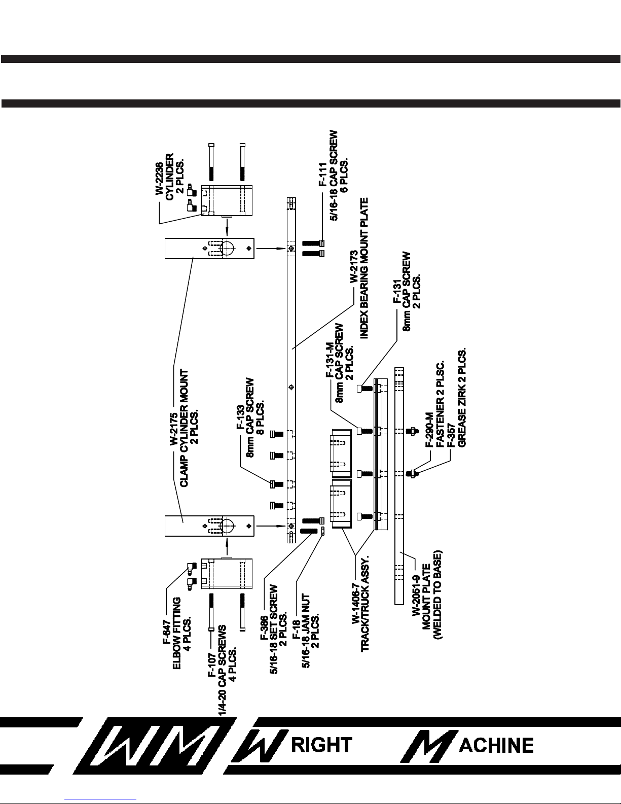
CLAMP FEED SYSTEM
QTY PART NUMBER DESCRIPTION
2 F-18 5/16-18 JAM NUT
4 F-107 1/4-20 CAP SCREW
6 F-111 5/16-18 CAP SCREW
2 F-131 8mm CAP SCREW
2 F-131-M 8MM CAP SCREW
8 F-133 8mm CAP SCREW
2 F-290-M 8MM HEX BOLT
2 F-357 GREASE ZIRK
2 F-386 5/16-18 SET SCREW
4 F-647 ELBOW FITTING
1 W-1406 TRACK/TRUCK ASSEMBLY
1 W-2051-9 MOUNT PLATE
1 W-2173 INDEX BEARING MOUNT PLATE
2 W-2175 CLAMP CYLINDER MOUNT
2 W-2236 AIR CYLINDER
29
Revised 1-2014
Page 31
W-1904-P QUAD DUAL SIDE GRINDER
FRONT VIEW OF CLAMP FEED SYSTEM
30
Revised 1-2014
Page 32

W-1904-P QUAD DUAL SIDE GRINDER
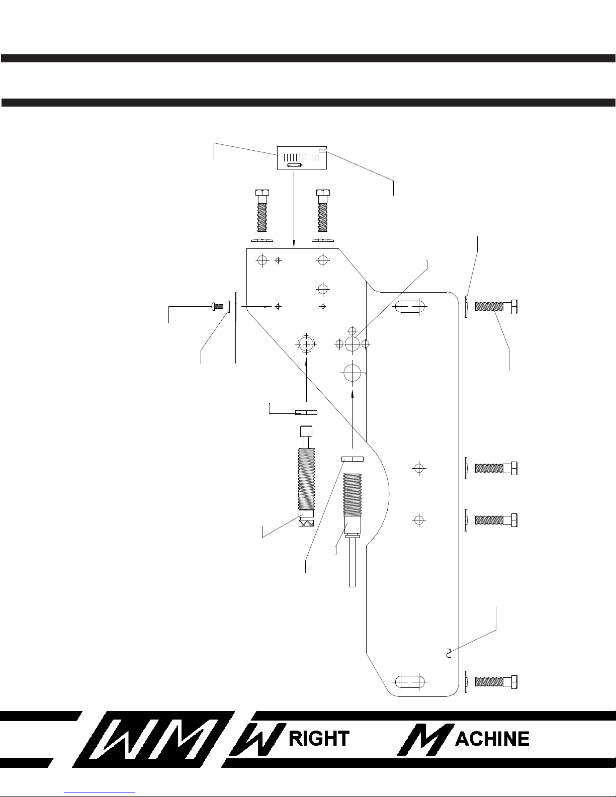
FRAME MOUNT FOR GRINDING HEAD
QTY PART NUMBER DESCRIPTION
2 F-54 #6 WASHER
3 F-56 #10 WASHER
3 F-59 FENDER WASHER
7 F-70 BELLEVILLE WASHER
7 F-279 3/8-16 HEX HEAD BOLT
3 F-333 10-24 SET SCREW
2 F-335 6-32 CAP SCREW
1 W-1051-C CYLINDER JAM NUT
1 W-1051-1 DAMPENER CYLINDER
1 W-2131 FRAME
1 W-2200 RADIAL SCALE
1 W-2207 PROXIMITY SWITCH
31
Revised 1-2014
Page 33
W-1904-P QUAD DUAL SIDE GRINDER
F-279
3/8 HEX HEAD BOLT
7 PLCS.
F-70
BELLVILLE WASHER
7 PLCS.
SEE "FEED LIMIT" ASSEMBLY
FOR LOCATION OF COMPONENTS
W-1051-1
DAMPENER CYLINDER
W-1051-C
CYLINDER JAM NUT
W-2207
PROXIMITY SWITCH
JAM NUT
W-2131
FRAME
F-333
10-24 SCREW
F-56
#10 WASHER
F-59
FENDER WASHER
3 PLCS.
3 PLCS.
3 PLCS.
024
6810
W-2200
RADIAL SCALE
F-335
6-32 SCREW
F-54
#6 WASHER
2 PLCS.
2 PLCS.
FRAME MOUNT FOR GRINDING HEAD
32
Revised 1-2014
Page 34

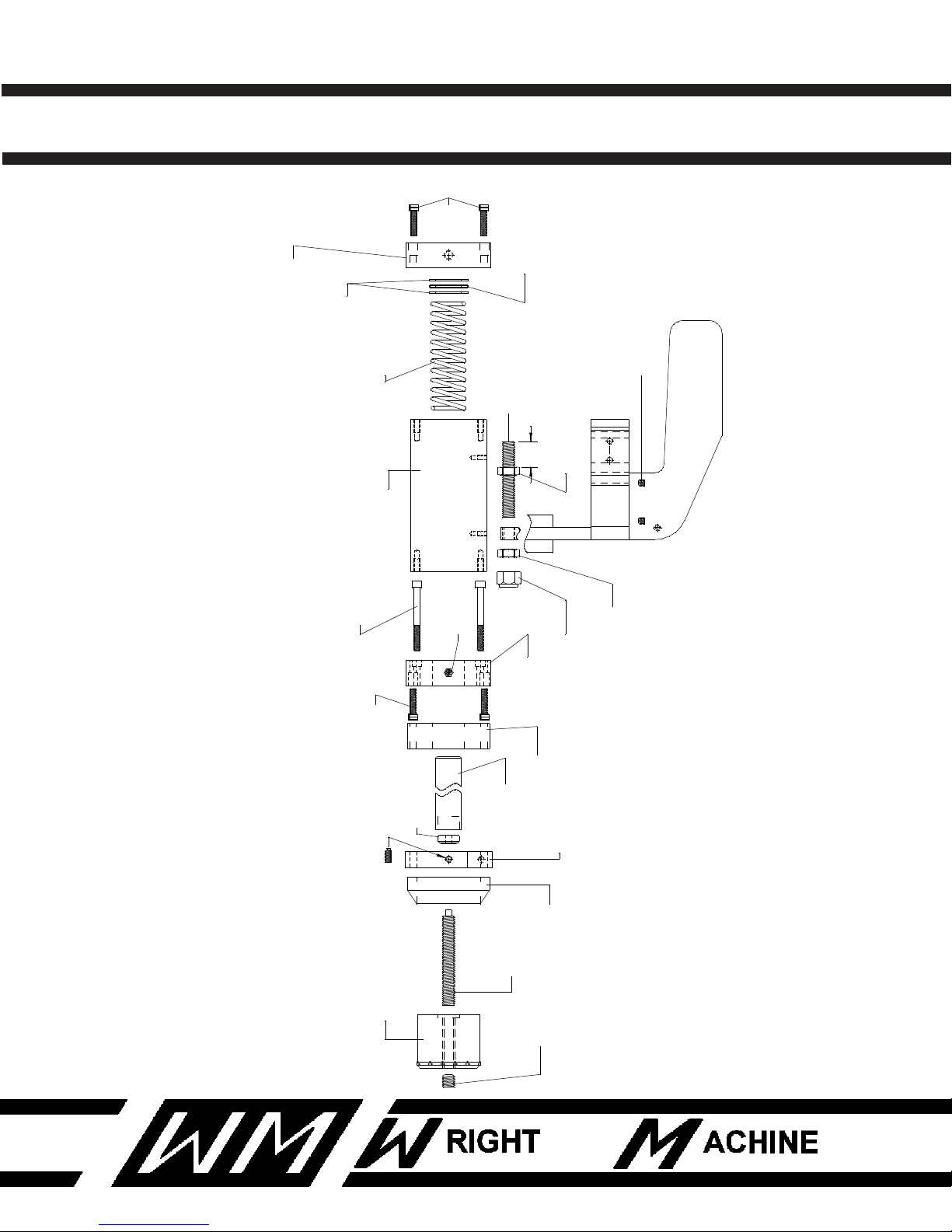
W-1904-P QUAD DUAL SIDE GRINDER
(INNER) GRINDING HEAD ASSEMBLY
QTY PART NUMBER DESCRIPTION
1 F-22 1/2-13 NUT
1 F-26 1/2-13 NUT
1 F-43 1/2-13 NYLOCK NUT
5 F-104 1/4-20 CAP SCREW
2 F-107 1/4-20 CAP SCREW
1 F-376 1/4-20 SET SCREW
1 F-392 1/2-20 SET SCREW
2 F-394 5/16-18 SET SCREW
1 W-357-2 ZERK FITTING
1 W-992 THRUST BEARING
1 W-1032-2 DEPTH FEED KNOB
1 W-1033 MARK RING
1 W-1055 LEAD SCREW
1 W-2124 DEPTH STOP SIDE
1 W-2153-A1 1/2-13 BOLT
1 W-2154-A BEARING BOSS
1 W-2154-B BEARING BOSS
1 W-2157 BEARING BOSS SPACER
1 W-2158 PIVOT SHAFT
1 W-2164 LEAD SCREW NUT
2 W-2217 FLAT GROUND WASHER
1 W-2218 THRUST WASHER
33
Revised 1-2014
Page 35
W-1904-P QUAD DUAL SIDE GRINDER
LOCATION OF
F-376 SET SCREW
W-2227
COMPRESSION SPRING
W-2164
LEAD SCREW NUT
W-992
THRUST BEARING
PIVOT SHAFT
W-2158
W-2124
DEPTH STOP SIDE
F-104
1/4-20 CAP SCREW
W-2154-B
BEARING BOSS
F-107
1/4-20 CAP SCREW
2 PLCS.
W-2157
BEARING BOSS SPACER
F-394
5/16-18 SET SCREW
2 PLCS.
W-1033
MARK RING
W-1055
LEAD SCREW
W-1032-2
DEPTH FEED KNOB
F-392
1/2-20 SET SCREW
W-2217
FLAT GROUND WASHER
2 PLCS.
W-2218
THRUST WASHER
W-2154-A
BEARING BOSS
5 PLCS.
F-104
W-357-2
ZERK FITTING
W-2153-A1
1/2-13 BOLT
1"
F-22
1/2-13 NUT
F-43
F-26
1/2-13 NUT
1/2-13 NUT (NYLOCK)
INNER GRINDING HEAD ASSEMBLY
34
Revised 1-2014
Page 36

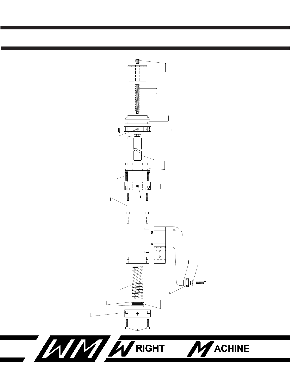
W-1904-P QUAD DUAL SIDE GRINDER
(OUTER) GRINDING HEAD ASSEMBLY
QTY PART NUMBER DESCRIPTION
5 F-104 1/4-20 CAP SCREW
2 F-107 1/4-20 CAP SCREW
1 F-376 1/4-20 SET SCREW
1 F-392 1/2-20 SET SCREW
2 F-394 5/16-18 SET SCREW
1 W-71 WASHER
1 W-357-2 ZERK FITTING
1 W-733 BEARING
1 W-992 THRUST BEARING
1 W-1032-2 DEPTH FEED KNOB
1 W-1033 MARK RING
1 W-1055 LEAD SCREW
1 W-2124 DEPTH STOP SIDE
1 W-2153-B OUTSIDE MOTOR ARM WELDMENT
1 W-2154-A BEARING BOSS
1 W-2154-B BEARING BOSS
1 W-2157 BEARING BOSS SPACER
1 W-2158 PIVOT SHAFT
1 W-2164 LEAD SCREW NUT
1 W-2187 ECCENTRIC
1 W-2217 FLAT GROUND WASHER
1 W-2218 THRUST WASHER
1 W-2227 COMPRESSION SPRING
35
Revised 1-2014
Page 37
W-1904-P QUAD DUAL SIDE GRINDER
LOCATION OF
F-376 SET SCREW
W-2227
COMPRESSION SPRING
W-2164
LEAD SCREW NUT
W-992
THRUST BEARING
PIVOT SHAFT
W-2158
W-2124
DEPTH STOP SIDE
F-104
1/4-20 CAP SCREW
W-2154-B
BEARING BOSS
F-107
1/4-20 CAP SCREW
2 PLCS.
W-2157
BEARING BOSS SPACER
W-2153-B
W-71
WASHER
W-733
BEARING
F-104
W-2187
ECCENTRIC
F-394
5/16-18 SET SCREW
2 PLCS.
W-1033
MARK RING
W-1055
LEAD SCREW
W-1032-2
DEPTH FEED KNOB
F-392
1/2-20 SET SCREW
W-2217
FLAT GROUND WASHER
2 PLCS.
W-2218
THRUST WASHER
W-2154-A
BEARING BOSS
5 PLCS.
F-104
W-357-2
ZERK FITTING
OUTSIDE MOTOR ARM WELDMENT
OUTER GRINDING HEAD ASSEMBLY
36
Revised 1-2014
Page 38

W-1904-P QUAD DUAL SIDE GRINDER
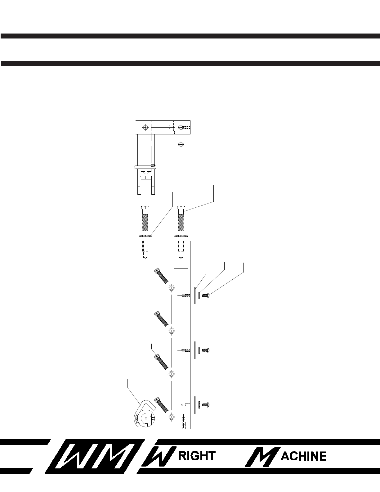
GRIND HEAD ARM ASSEMBLY
QTY PART NUMBER DESCRIPTION
8 F-56 #10 WASHER
8 F-59 FENDER WASHER
6 F-70 BELLEVILLE WASHER
4 F-104 1/4-20 CAP SCREW
6 F-279 3/8-16 HEX HEAD BOLT
1 F-284 5/8 UNF HEX HEAD BOLT
8 F-333 10-24 CAP SCREW
1 F-436 1/4 X 1 DOWEL PIN
2 W-2132-2 CYLINDER PIVOT MOUNT
37
Revised 1-2014
Page 39
W-1904-P QUAD DUAL SIDE GRINDER
F-333
10-24 SCREW
F-56
#10 WASHER
F-59
FENDER WASHER
F-104
1/4-20 BOLT
4 PLCS.
3 PLCS.
3 PLCS.
3 PLCS.
W-2132-2
CYLINDER PIVOT MOUNT
F-279
3/8 HEX HEAD BOLT
3 PLCS.
F-70
BELLVILLE WASHER
3 PLCS.
ROUGH HEAD
GRIND HEAD ARM ASSEMBLY
38
Revised 1-2014
Page 40

W-1904-P QUAD DUAL SIDE GRINDER
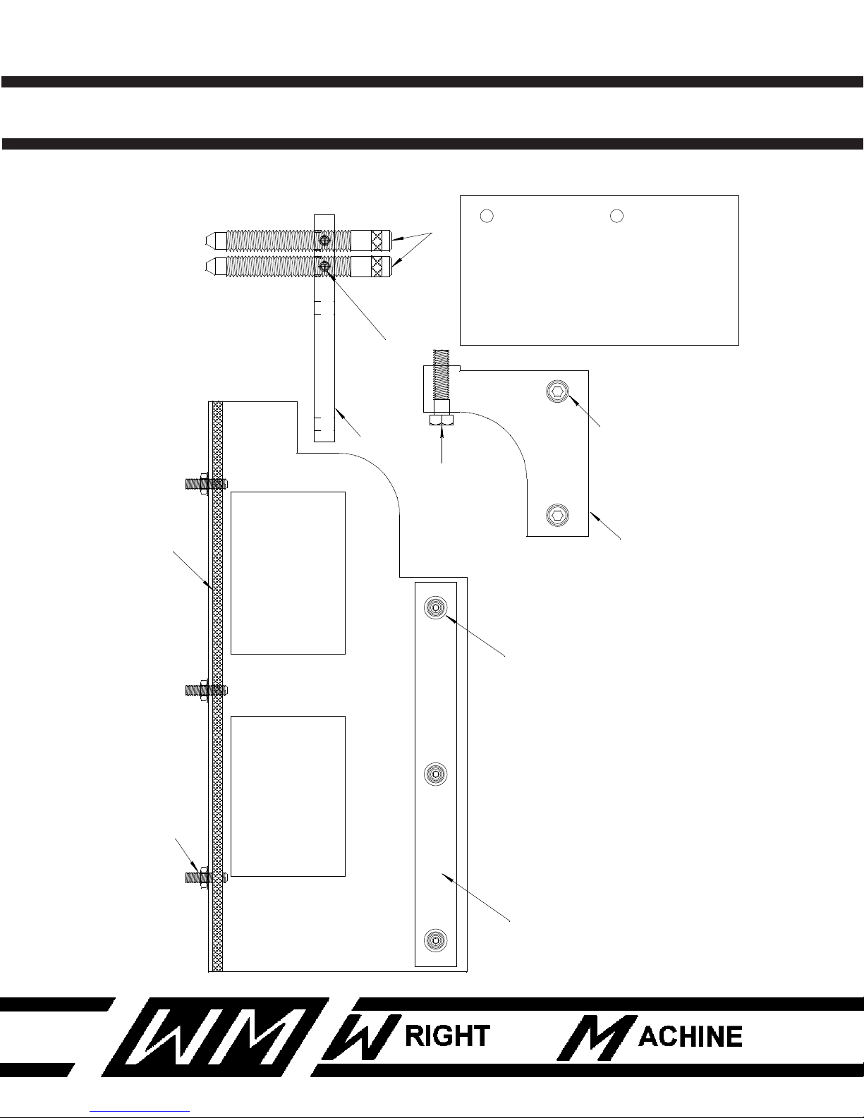
GRINDING HEAD COVERS
QTY PART NUMBER DESCRIPTION
3 F-12 1/4-20 JAM NUT
3 F-61 #12 WASHER
2 F-118 3/8 - 16 X 1-1/4 SHCS
1 F-279 3/8 - 16 X 1-1/2 HEX HEAD
3 F-358 1/4-20 X 1/2 BUTTON HEAD
2 F-376 1/4-20 X 1/2 SET SCREW
3 F-398 1/4-20 X 1 SET SCREW
1 W-2116-1 SUPPORT GUSSET
1 W-2116-5 RUBBER FLAP CLAMP
2 W-2124 DEPTH STOP
1 W-2125 STOP BRACKET
1 W-2128-1 BOTTOM COVER
1 W-2128-2 RUBBER FLAP CLAMP
1 W-2130 TRACK COVER
39
Revised 1-2014
Page 41
W-1904-P QUAD DUAL SIDE GRINDER
W-2116-1
W-2124
W-2125
W-2128-1
W-2128-2
W-2116-5
F-279
F-376
F-358 X 3
F-61 X 3
F-118 X 2
F-398 X 3
F-61 X 3
F-12 X 3
W-2130
GRINDING HEAD COVERS
40
Revised 1-2014
Page 42

W-1904-P QUAD DUAL SIDE GRINDER
FEED FINGER ASSEMBLY
QTY PART NUMBER DESCRIPTION
1 F-12 1/4-20 JAM NUT
1 F-32 3/8-24 JAM NUT
1 F-38 NYLOCK NUT 3/8-24
1 F-102 SHCS 1/4-20 X 1-1/2
2 F-104 1/4-20 CAP SCREW
1 F-106 SHCS 1/4-20 X 5/8
2 F-122 3/8-16 CAP SCREW
1 F-379 SET SCREW 1/4-20 X 5/8
1 F-391 1/4-20 SET SCREW
1 F-608 FITTING
1 F-612-1 SHUT OFF VALVE
1 F-620 ELBOW FITTING
1 F-660 FITTING
2 W-436 THRUST BEARING
1 W-437 WASHER (BEARING RACE)
1 W-263 SPRING
1 W-632-2 SPACER
5 W-667 FLAT GROUND WASHER
1 W-1294-C 1/8 N.P.T. CONNECTOR
1 W-1294-3 COOLANT FITTING
2 W-1411 O-RING
1 W-2184 FINGER BRACKET
1 W-2184-3 HOLD DOWN STRAP
1 W-2185 FINGER PIVOT
1 W-2186-2 INDEX FEED FINGER
1 W-2188 BEARING COVER
2 W-2188-1 BEARING COVER
41
Revised 1-2014
Page 43
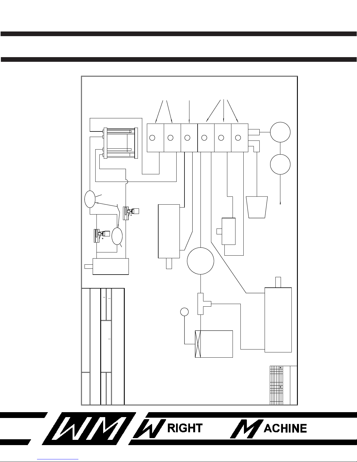
W-1904-P QUAD DUAL SIDE GRINDER
DRAWING NUMBER
REVISED
DRAWN BYAPPROVED BYSCALE
DATE
WRIGHT MACHINE TOOL
REGULATOR
80 PSI
W-161
FILTER
(TRAP)
MUFFLER
W-1442
EXH.
DRAG
CLAMP NC GRN
NC GRN
IN
AIR
INDEX
ROUGH
6
W-1537
NC BLU
NO BLU
NO YEL
NC YEL
NO RED
ROUGH
HEAD CYL.
W-2209-1
40 PSI. REG.
INDEX REV.
W-68
CLAMP CYL.
3 EA.
W-2236
IN
INDEX REV.
QUICK EXH.
W-162
OUT
INDEX CYL.
W-1402-M
8
NONE DGR
SHEET 1 OF 1
1
DATE
SYMBOL
APPD.
BY
CHANGE(S) MADE...
BY
DRAWN
1
DATE
SYMBOL
APPD.
BY
CHANGE(S) MADE...
CHANGE(S) MADE...
0-00-00LP
BY
DRAWN
NO RED
OUT
IN
W-465
FF
FREE FLOW
0 19
OIL POT
15
FINISH OUT
COUNTER
13
8
10
4
W1904W1904-PAIR
W-1904-P
06-03-03
SIDE FEED
CYLINDER
W-2209
W-465
FF
FREE FLOW
0 19
SLOW
FEED
SIDE
STOP VALVE
W-1009
STOP
VALVE
OUT
IN
#7
#9
FINISH IN
CLR
BLK
RED
W-1904-P AIR DIAGRAM
W-1538
W-1537
BC DP
MIRRORED FLOW VALVES
7-08-03
1
1
FEED FINGER ASSEMBLY
42
Revised 1-2014
Page 44
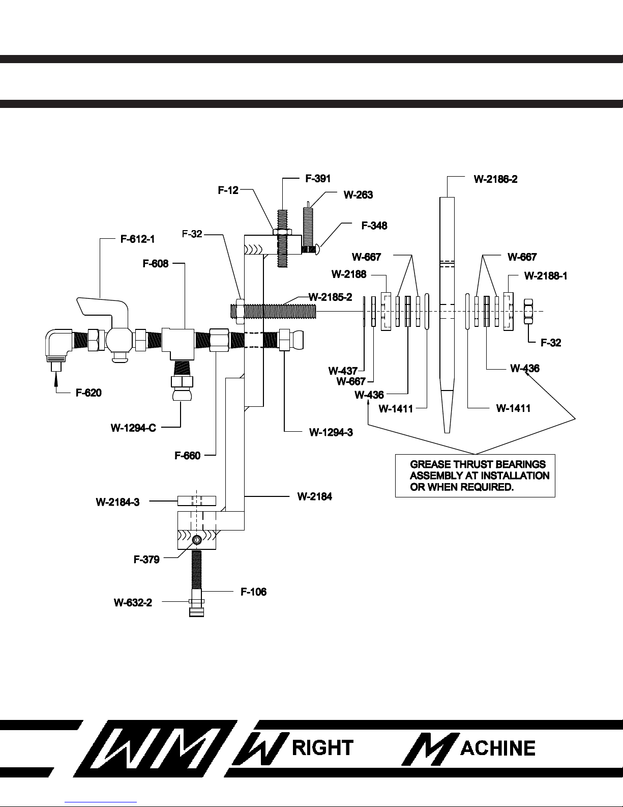
W-1904-P QUAD DUAL SIDE GRINDER
FEED FINGER ASSEMBLY
43
Revised 1-2014
Page 45

W-1904-P QUAD DUAL SIDE GRINDER
CLAMP ASSEMBLY
QTY PART NUMBER DESCRIPTION
1 F-24 1/2-20 NUT
5 F-110 5/16-18 CAP SCREW
2 F-392 1/2-20 SET SCREW
4 F-333-1 10-24 ROUND HEAD SCREW
2 F-407 3/16 ROLL PIN
1 W-2178-1 OUTER CLAMP JAW
1 W-2179 OUTER CLAMP STIFFENER
2 W-2181 CLAMP CYLINDER ATTACHMENT BRACKET
2 W-2182 CLAMP JAW ATTACHMENT BRACKET
4 W-2183 HOSE HOLDER
1 W-2236 CLAMP CYLINDER
2 W-2236-M CLAMP CYLINDER
1 W-2236-2 CYLINDER ADJUSTMENT BOLT
44
Revised 1-2014
Page 46
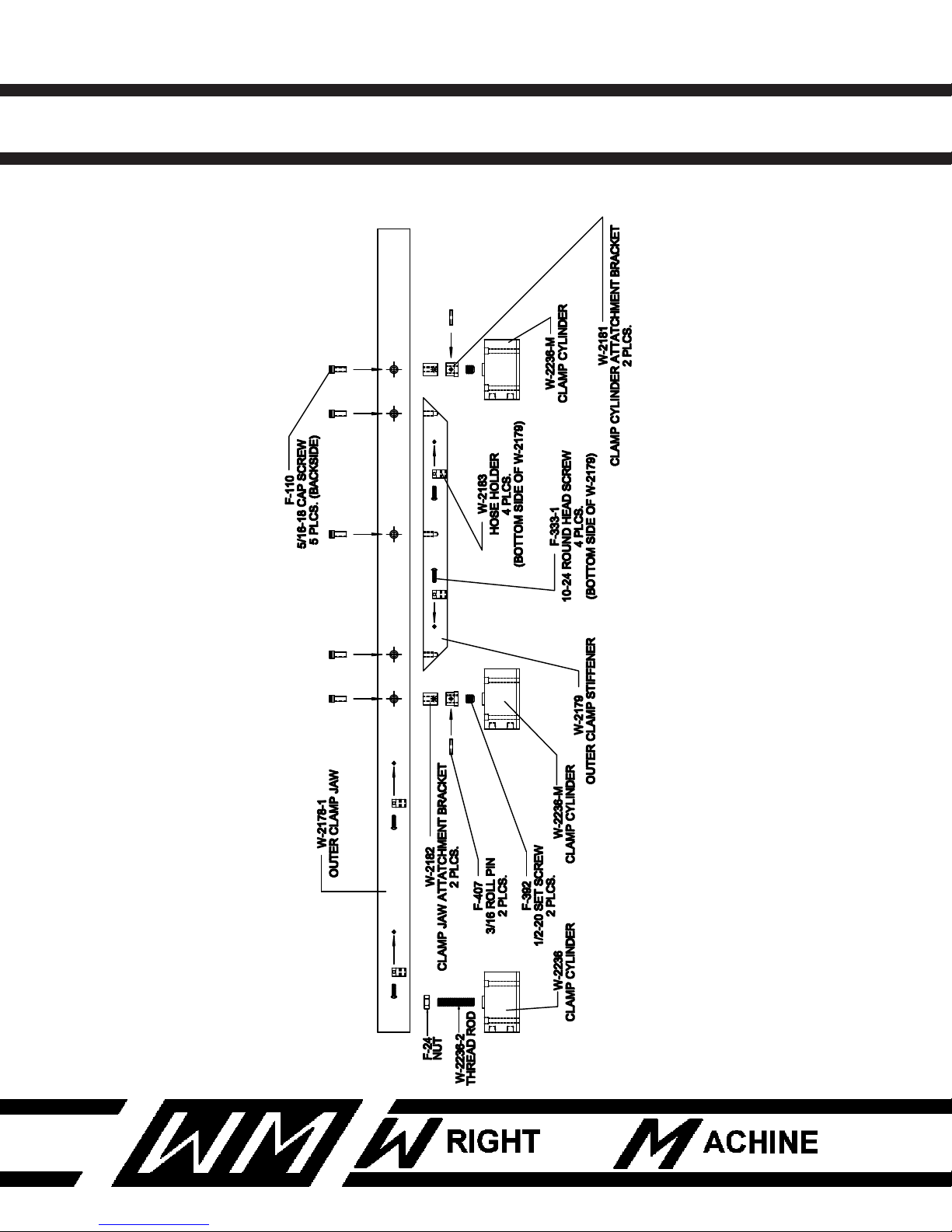
W-1904-P QUAD DUAL SIDE GRINDER
TOP VIEW OF CLAMP ASSEMBLY
45
Revised 1-2014
Page 47

W-1904-P QUAD DUAL SIDE GRINDER
INDEX ASSEMBLY
QTY PART NUMBER DESCRIPTION
1 F-25 1/4-20 NYLOCK NUT
1 F-31 1/2-13 ACORN NUT
6 F-58 WASHER
1 F-102 1/4-20 CAP SCREW
7 F-114 5/16-18 CAP SCREW
2 F-119 5/16-18 CAP SCREW
1 F-268-M 1/2-13 BOLT (MODIFIED)
2 F-313 1/4-20 FLAT HEAD SCREW
2 F-333 10-24 SCREW
2 F-378 1/4-20 SET SCREW
2 F-380 1/4-20 SET SCREW
1 F-434 1/4 DIA. PIN
2 F-671 AIR FITTING
1 W-284 WASHER
1 W-508 TOMSON SHAFT
1 W-1000-1 NUT
1 W-1402-M HEAVY DUTY INDEX AIR CYLINDER
1 W-1404 PROXIMITY SWITCH
1 W-1469 ENDINE CYLINDER
1 W-2032 CLEVIS
1 W-2033 CYLINDER LINK
1 W-2034 MOUNT BRACKET (B)
1 W-2035 MOUNT BRACKET (A)
1 W-2036 MOUNT BRACKET (C)
1 W-2450 MOUNT BRACKET
1 W-2451 TARGET CYLINDER
46
Revised 1-2014
Page 48
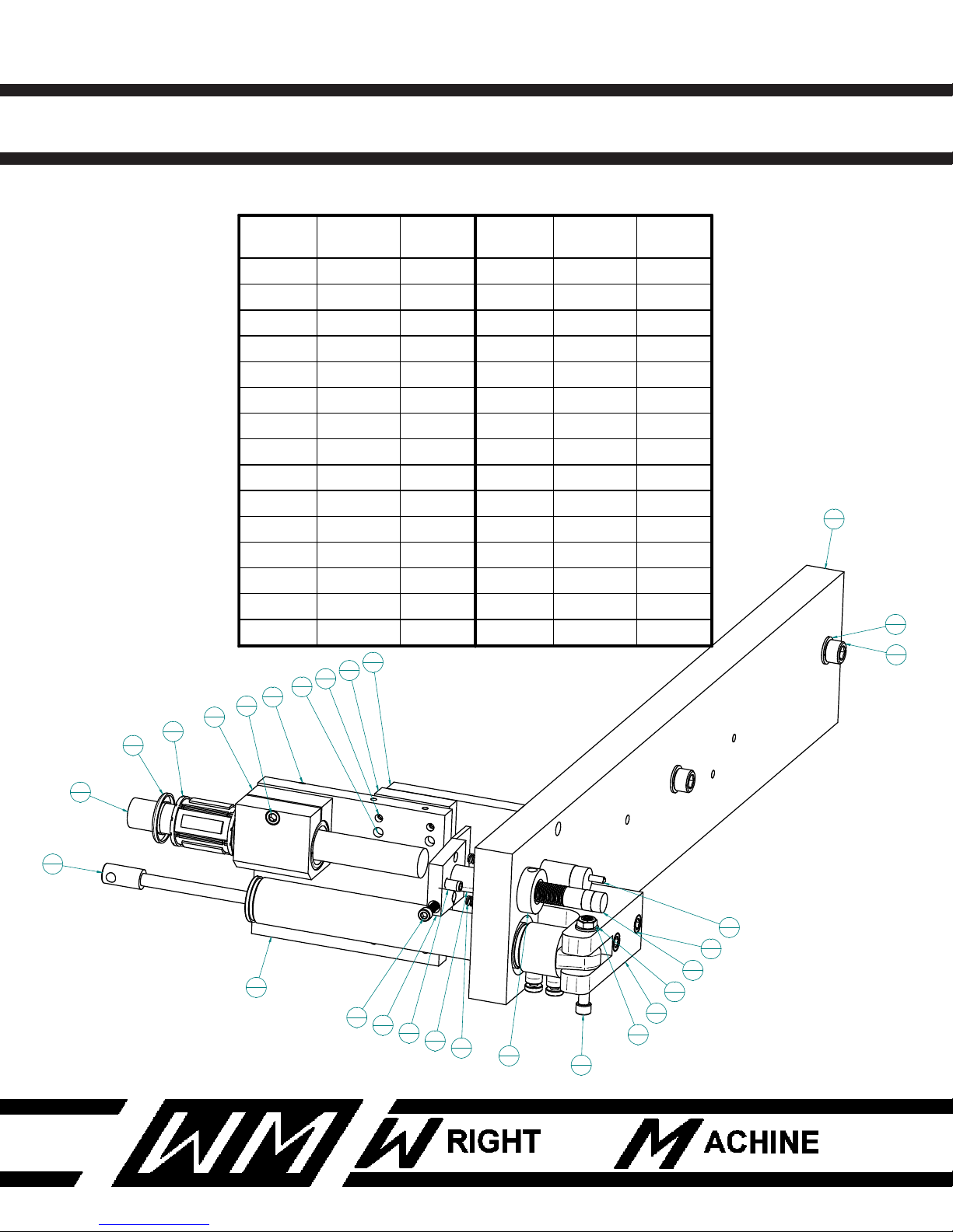
W-1904-P QUAD DUAL SIDE GRINDER
9
1
25
1
1
1
23
1
12
1
11
1
10
1
7
1
4
1
6
1
8
1
21
1
18
2
19
1
17
1
20
1
24
2
15
4
30
2
26
1
22
1
28
1
16
2
13
4
3
1
29
2
27
1
2
2
Item
Number
PART # Quantity
1 W-2031 1
2 W-382 2
3 F-410 1
4 W-2452 1
5* F-378 1
6 W-2453 1
7 W-2124 1
8 W-2454 1
9 W-1404 1
10 W-2036 1
11 W-2035 1
12 W-2034 1
13 F-377 4
14* F-58 4
15 F-114 4
Item
Number
PART # Quantity
16 F-313 2
17 C-5053 1
18 W-513 2
19 W-514 1
20 F-102 1
21 W-508 1
22 F-140 1
23 W-2032 1
24 F-113-1 2
25 W-1469 1
26 F-127 1
27 F-61 1
28 F-25 1
29 F-60 2
30 F-122 2
INDEX ASSEMBLY
47
Revised 1-2014
Page 49

W-1904-P QUAD DUAL SIDE GRINDER
INDEX CYLINDER ASSEMBLY, ROUGHING HEAD
QTY PART NUMBER DESCRIPTION
1 F-23 3/8-16 NYLOCK NUT
1 F-11 10-24 NUT
2 F-60 5/16 WASHER
1 F-122 3/8-16 BOLT
1 F-137 10-24 BOLT
2 F-671 HOSE FITTING
1 W-1000-1 CYLINDER NUT
1 W-1403 ROD END
1 W-1404 PROXIMITY SWITCH
1 W-2132-2 CYLINDER PIVOT MOUNT
1 W-2209-1 AIR CYLINDER
1 W-2228 HEAD RETURN SPRING
1 W-2450 SPACER
1 W-2451 CYLINDER TARGET
48
Revised 1-2014
Page 50
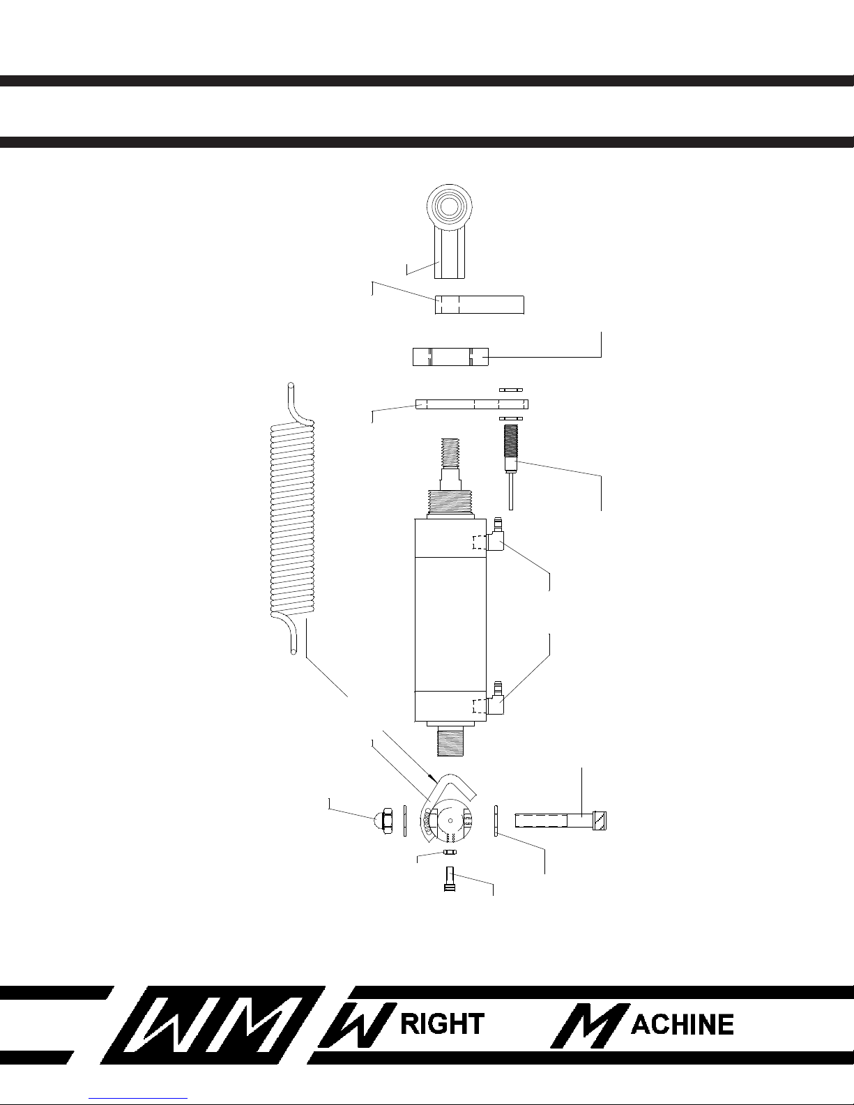
W-1904-P QUAD DUAL SIDE GRINDER
W-2209-1
AIR CYLINDER
F-671
HOSE FITTING
2 PLCS.
W-2132-2
CYLINDER PIVOT MOUNT
F-122
F-23
3/8-16 NYLOCK NUT
F-11
10-24 NUT
F-137
10-24 BOLT
3/8-16 BOLT
F-60
5/16 WASHER
2 PLCS.
W-1404
PROXIMITY SWITCH
W-2450
SPACER
W-2451
CYLINDER TARGET
W-1403
ROD END
W-1000-1
CYLINDER NUT
W-2228
HEAD RETURN SPRING
SPRING
LOCATION
INDEX CYLINDER ASSEMBLY, ROUGHING HEAD
49
Revised 1-2014
Page 51

W-1904-P QUAD DUAL SIDE GRINDER
FEED LIMIT ASSEMBLY
QTY PART NUMBER DESCRIPTION
1 F-140 10-24 CAP SCREW
1 F-378 1/4-20 SET SCREW
2 F-382 SPRING
1 F-410 ROLL PIN
1 W-2124 DEPTH STOP
1 W-2452 TARGET FRAME
1 W-2453 DEPTH NUT
1 W-2454 SET COLLAR
50
Revised 1-2014
Page 52
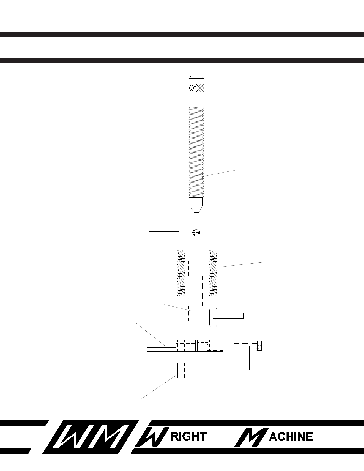
W-1904-P QUAD DUAL SIDE GRINDER
W-382
SPRING
W-2453
DEPTH NUT
2 PLCS.
F-410
ROLL PIN
W-2454
SET COLLAR
W-2124
DEPTH STOP
F-140
10-24 CAP SCREW
F-378
1/4-20 SET SCREW
W-2452
TARGET FRAME
FEED LIMIT ASSEMBLY
51
Revised 1-2014
Page 53

W-1904-P QUAD DUAL SIDE GRINDER
HEAD FEED UP AND DOWN
QTY PART NUMBER DESCRIPTION
1 F-15 1/4-20 JAM NUT
1 F-19 3/8-16 NUT
1 F-58 1/4 WASHER
1 F-114 5/16-18 X 1-1/2 SHCS
1 F-118 3/8 - 16 X 1-1/4 SHCS
1 F-119 3/8-16 X 2-1/4 SHCS
12 F-134 8mm X 25mm SHCS
1 F-287 1/2-13 HEX HEAD BOLT
2 F-357 10-24 X 1-1/2 RND HEAD SLOT
1 F-631 FITTING
2 F-638 BARBED FITTING
1 W-177 SPRING
2 W-284 GROUND WASHER
1 W-437 WASHER (BEARING RACE)
2 W-731 MICRO SWITCH
1 W-1406-2 TRUCKS AND RAIL
1 W-1406-9 LUBRICATOR BOLT
1 W-2116-3 TRACK MOUNT
52
Revised 1-2014
Page 54
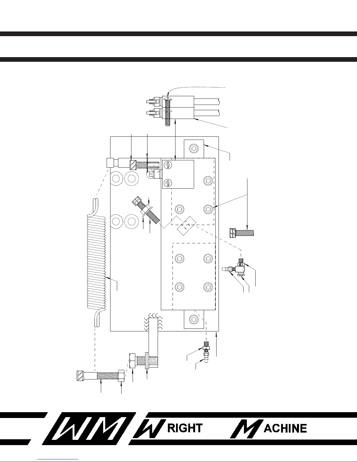
W-1904-P QUAD DUAL SIDE GRINDER
W-177
W-2116-3
W-287
F-134 X 12
F-1406-2
F-118
W-437
F-19
F-119
W-284 X 2
W-1406-9
F-638
W-1406-9
F-631
F-638
F-357 X 2
LS2 LS3
W-731 X 2
F-114
F-58
F-15
HEAD FEED UP AND DOWN
53
Revised 1-2014
Page 55

W-1904-P QUAD DUAL SIDE GRINDER
HEAD FEED CYLINDER ASSEMBLY
QTY PART NUMBER DESCRIPTION
3 F-608 FITTINGS
1 F-610 1/8 NPT FITTING
2 F-614 1/8 NPT HEX NIPPLE
1 F-616 1/8 TO 1/4 BUSHING
2 F-620 ELBOW FITTING
1 F-622 1/8 X 3/8 NPT MALE CONNECTOR
2 F-638 BARBED FITTING
2 W-465 FLOW CONTROL
2 W-748 BLEEDER VALVE
1 W-1403 ROD END
1 W-2209 AIR CYLINDER
54
Revised 1-2014
Page 56
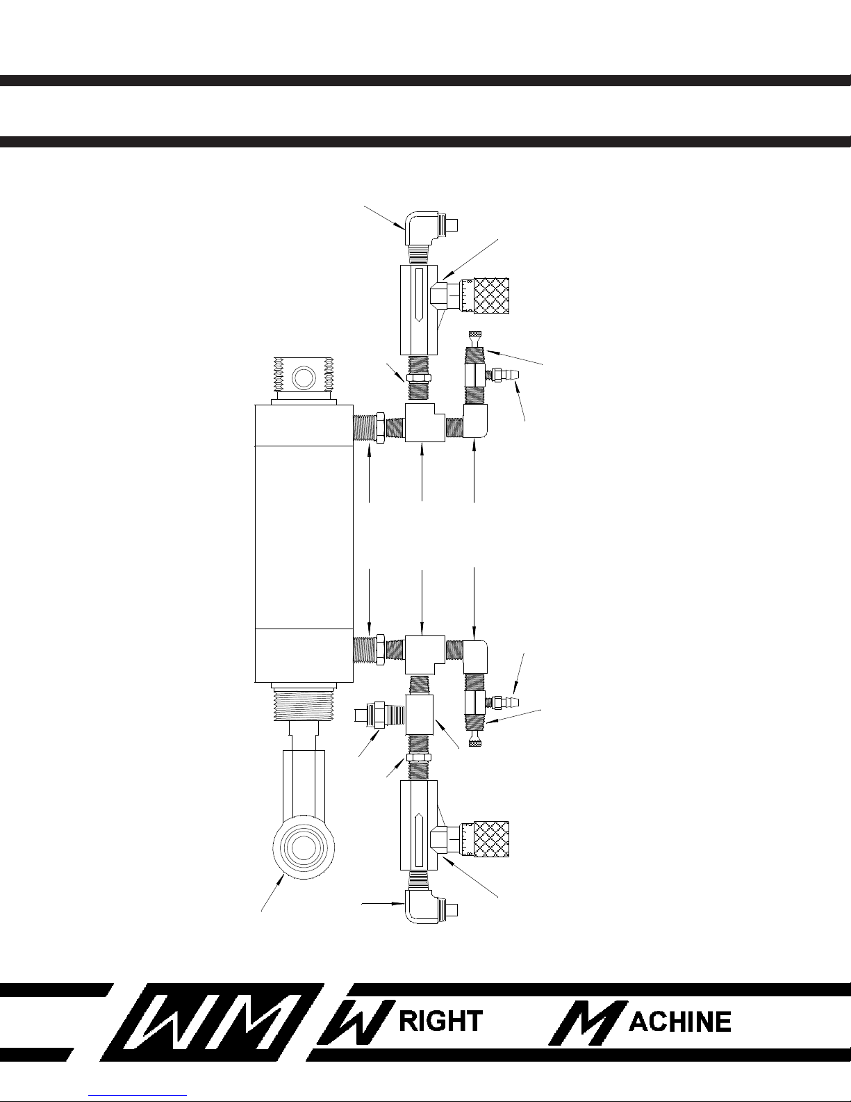
W-1904-P QUAD DUAL SIDE GRINDER
FREE FLOW
3
1
2
01 9
W-465
W-1403
W-2209
F-620
F-608
F-614
F-616
F-610
F-638
W-748
F-622
FREE FLOW
3
1
2
0 19
F-608
F-620
W-465
F-638
W-748
F-614
HEAD FEED CYLINDER ASSEMBLY
55
Revised 1-2014
Page 57

W-1904-P QUAD DUAL SIDE GRINDER
HEAD INFEED ASSEMBLY
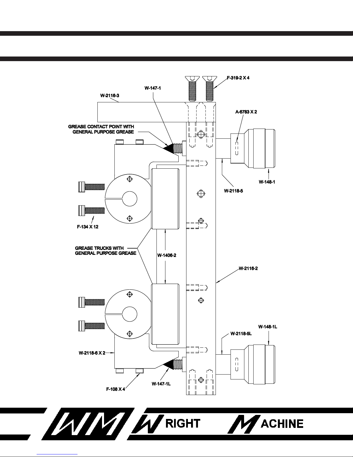
QTY PART NUMBER DESCRIPTION
2 A-6783 RUBBER O-RING
4 F-108 1/4-20 X 2 SHCS
12 F-134 8mm X 25mm SHCS
4 F-319-2 3/8-16 X 1 FLAT HEAD
1 W-147-1 LEAD SCREW (R.H)
1 W-147-1L LEAD SCREW (L.H)
1 W-148-1 HAND FEED KNOB (R.H)
1 W-148-1L HAND FEED KNOB (L.H)
1 W-1406-2 TRUCKS AND RAIL
1 W-2116-2 TRACK MOUNT
1 W-2116-3 TRACK MOUNT( LEFT END)
1 W-2118-5 STAND OFF KNOB (R.H)
1 W-2118-5L STAND OFF KNOB (L.H)
2 W-2118-6 LEAD SCREW TARGET
56
Revised 1-2014
Page 58
W-1904-P QUAD DUAL SIDE GRINDER
HEAD IN FEED ASSEMBLY
57
Revised 1-2014
Page 59

W-1904-P QUAD DUAL SIDE GRINDER
OIL POT INFEED
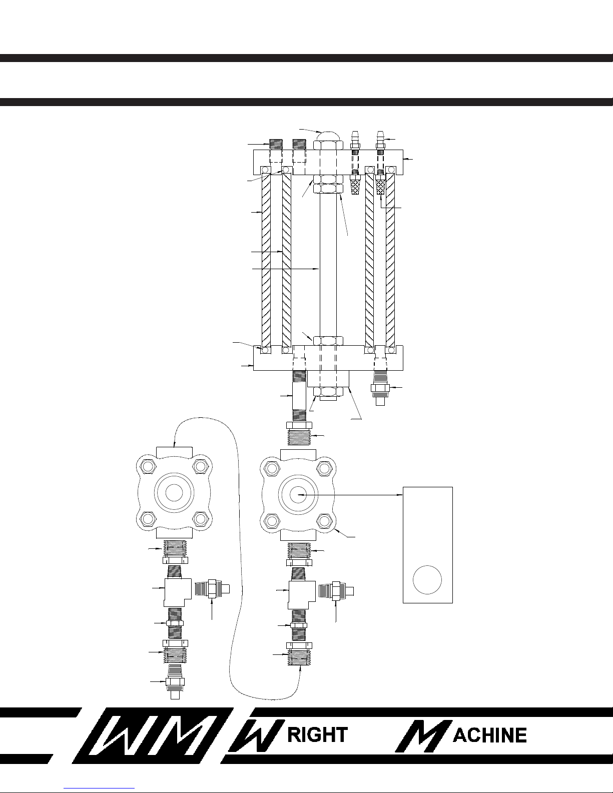
QTY PART NUMBER DESCRIPTION
1 F-22 1/2-13 JAM NUT
1 F-24 1/2-20 JAM NUT
1 F-31 1/2-13 ACORN NUT
1 F-41 1/2-13 HYDRA-LOK NUT
1 F-42 1/2-20 HYDRA-LOK NUT
2 F-608 FITTING
2 F-614 HEX NIPPLE
5 F-617 BUSHING
4 F-622 1/8 NPT X 3/8 NPT CONNECTOR
2 F-634 1/8 NPT PLUG
2 F-638 BARBED FITTING
1 F-663 NIPPLE
2 W-730-1 AIR FITTING
2 W-757 O-RING
2 W-1009 VALVE
1 W-1009-1 SOLENOID
2 W-1158 O-RING
1 W-1171 BOTTOM LARGE END CAP
1 W-1172 TOP END CAP
1 W-2194 STUD
1 W-2195 OIL TUBE
1 W-2196 OIL TUBE
1 W-2486-2 OIL POT BRACKET
58
Revised 1-2014
Page 60
W-1904-P QUAD DUAL SIDE GRINDER
F-42
F-24
W-1158
2 PLCS
W-757
2 PLCS.
F-31
F-22
F-41
W-2195
W-2196
W-2194
W-2846-2
W-1172
W-1171
F-638 X 2
F-634 X 2
W-730-1 X 2
OUT
IN
F-617
F-622
F-608
OUT
IN
F-617
F-622
F-614
F-617
F-622
F-608
F-617
F-614
F-663
F-622
W-1009 X 2
W-1009-1
F-617
OIL POT INFEED ASSEMBLY
Oil pot should be 2/3 full of
AW32 10w hydraulic oil,
inner and outer chamber.
59
Use suction gun with flex
tubing to add oil to pot.
Air bleed at cylinder.
Revised 1-2014
Page 61

W-1904-P QUAD DUAL SIDE GRINDER
SPINDLE MOTOR ASSEMBLY
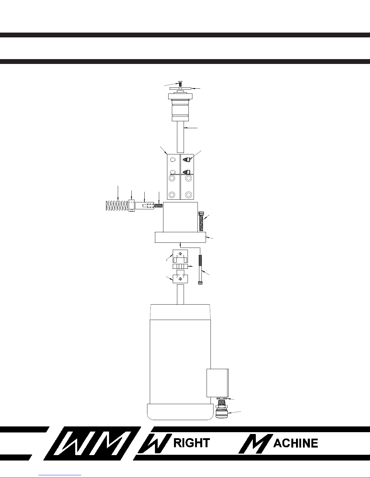
QTY PART NUMBER DESCRIPTION
8 F-101 1/4-20 X 5/8 SHCS
4 F-107 1/4-20 X 20 SHCS
8 F-114 5/16-18 X 1-1/2 SHCS
2 F-304 10-24 X 1/2 SHCS
2 F-385 5/16-18 X 3/4 SET SCREW
2 W-209 INFEED SPRING
2 W-210-1 LOCK NUT FOR W-1460-1
2 W-462 5/8 COLLAR
2 W-658 WHEEL NUT
2 W-1166-A SPINDLE ASSEMBLY
2 W-1409-1 1 HP MOTOR
2 W-1460-1 CORD GRIP
2 W-2286 COUPLING
2 W-2287 SPIDER GEAR
2 W-2112 MOTOR ADAPTER
2 W-2112-1 SPRING POLE
2 W-2117-3 SPINDLE HOUSING
2 W-2117-4 SPINDLE HOUSING
60
Revised 1-2014
Page 62
W-1904-P QUAD DUAL SIDE GRINDER
F-101 X 4
W-1166-A
W-2112
W-209
W-462
F-385
W-2287
W-1460-1
W-210-1
W-2286
W-2112-1
W-658
F-304
W-1409-1
1 HP MOTOR
F-107 x 2
F-114 x 4
W-2117-3 & 4
SPINDLE MOTOR ASSEMBLY
61
Revised 1-2014
Page 63

W-1904-P QUAD DUAL SIDE GRINDER
SPINDLE GUARD HOUSING
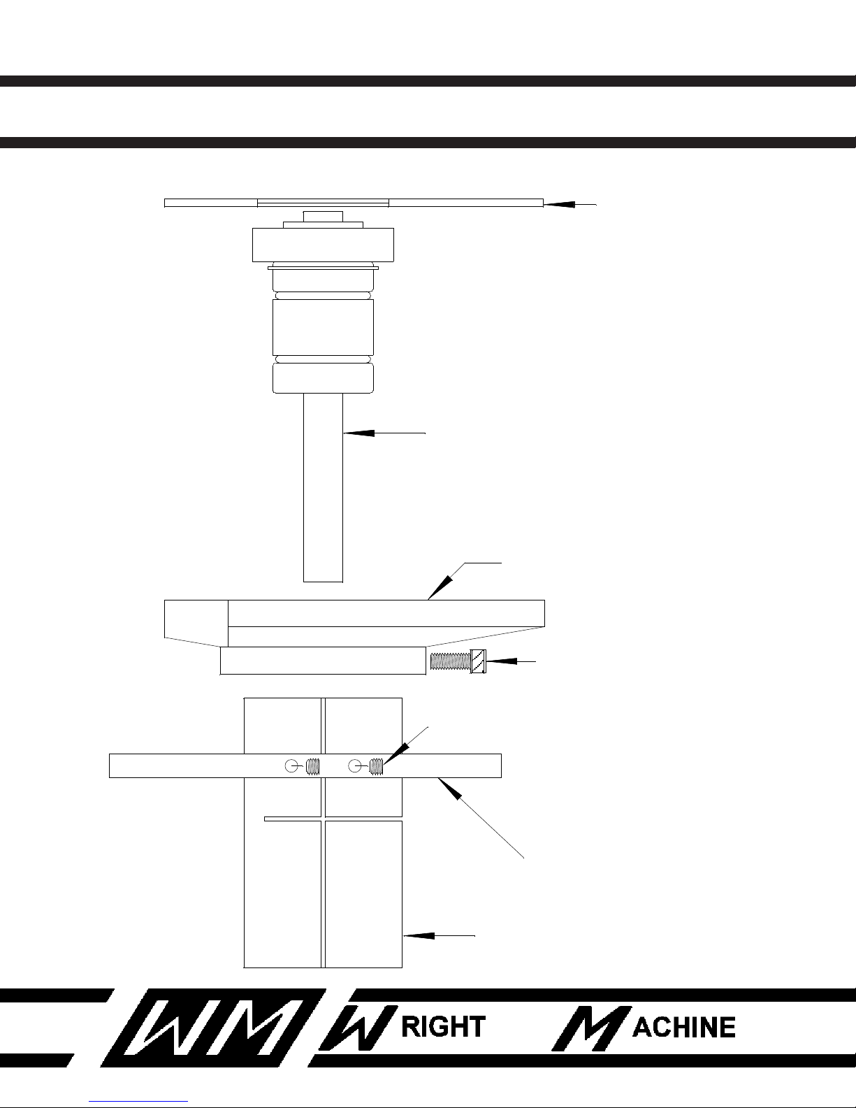
QTY PART NUMBER DESCRIPTION
6 F-101 1/4-20 X 5/8 SHCS
4 F-380 1/4-20 X 1/4 SET SCREW
2 W-1166-A SPINDLE ASSEMBLY
1 W-2113-R RIGHT WHEEL GUARD
1 W-2113-L LEFT WHEEL GUARD
2 W-2114 SIDE WHEEL COVER
1 W-2117-3 RIGHT SPINDLE HOUSING
1 W-2117-4 LEFT SPINDLE HOUSING
1 W-2126-2R RIGHT SPINDLE SHIELD
1 W-2126-2L LEFT SPINDLE SHIELD
62
Revised 1-2014
Page 64
W-1904-P QUAD DUAL SIDE GRINDER
W-1166-A
W-2114
F-380
F-101 X 3
W-2113-R OR L
W-2126-2R OR 2L
W-2117-3 OR 4
SPINDLE GUARD HOUSING
63
Revised 1-2014
Page 65

W-1904-P QUAD DUAL SIDE GRINDER
SAW LIFT ASSEMBLY
QTY PART NUMBER DESCRIPTION
8 F-19 3/8-16 NUT
4 F-20 5/16-18 A-CORN NUT
4 F-22 1/2-13 NUT
8 F-29 3/8-16 A-CORN NUT
4 F-58 1/4" WASHER
4 F-110 5/16-18 CAP SCREW
16 F-116 3/8-16 CAP SCREW
1 F-268 1/2-13 HEX BOLT
1 F-287 1/2-13 HEX BOLT
8 F-64 10mm WASHER
2 F-438 WOODRUF KEY
4 W-284 GROUND WASHER
4 W-330 5/8 BORE PILLOW BLOCK
4 W-1318 1/2-13 STUD
1 W-2089 SAW LIFT FRAME
2 W-2090 SAW LIFT NUT/GUIDE
2 W-2091 LEAD SCREW
1 W-2093 CHAIN TENSION ARM
1 W-2211 DRIVE SPROCKET
4 W-2212 SPROCKET
1 W-2213 IDELER SPROCKET
1 W-2224 SAW LIFT DRIVE MOTOR
64
Revised 1-2014
Page 66
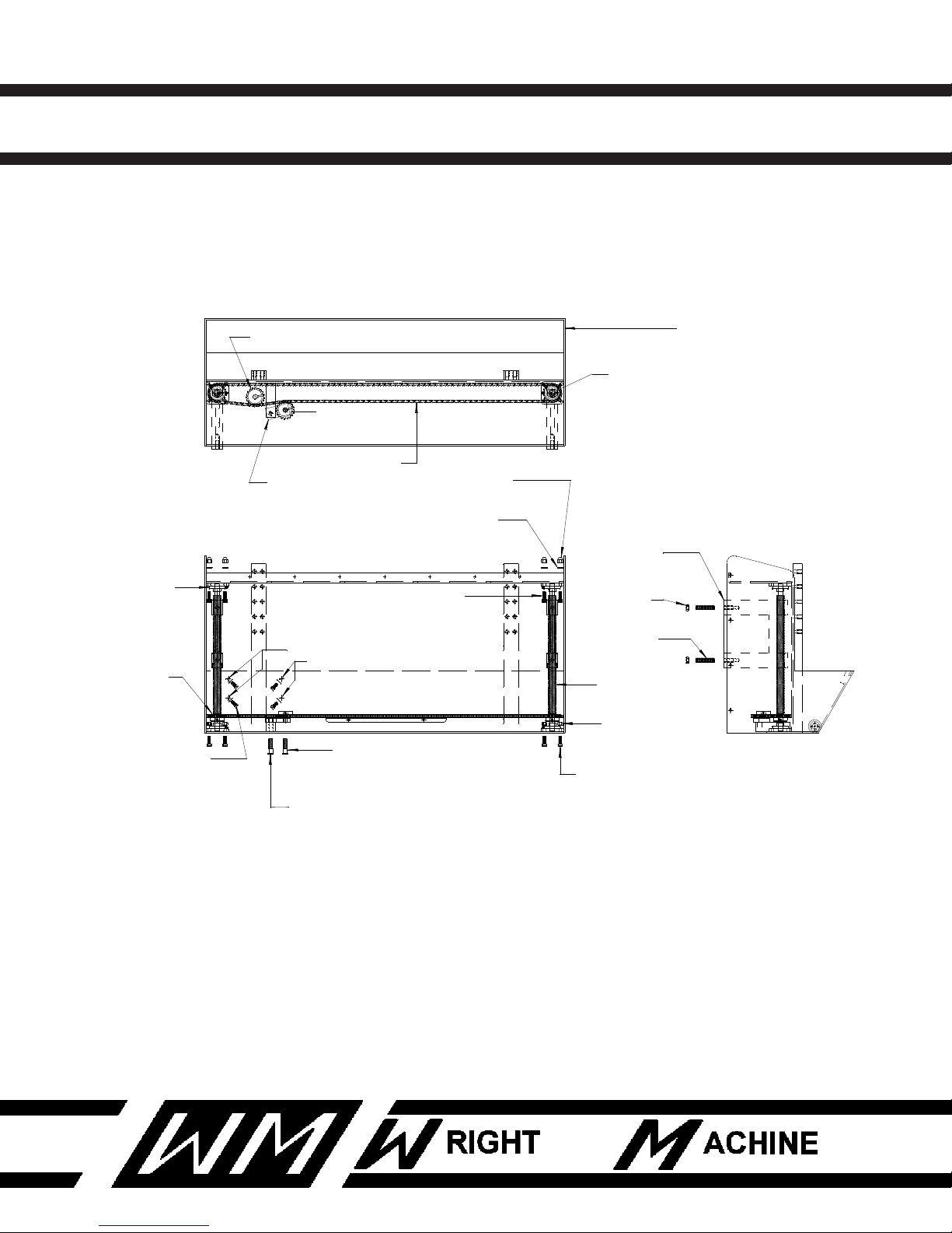
W-1904-P QUAD DUAL SIDE GRINDER
W-330
PILLOW BLOCK
4 PLCS.
SPROCKET LOCATED ON MOTOR SHAFT
W-2091
LEAD SCREW
2 PLCS.
129 LINK CHAIN
W-2090
SAW LIFT NUT/GUIDE
2 PLCS.
(BACK VIEW)
(TOP VIEW)
(SIDE VIEW)
MOUNT LOCATIONS FOR
F-110
5/16-18 CAP SCREW
4 PLCS.
F-58
1/4" WASHER
4 PLCS.
F-22
1/2-13 NUT
4 PLCS.
W-1318
1/2-13 STUD
4 PLCS.
F-438
WOODRUF KEY
2 PLCS.
F-29
3/8-16 A-CORN NUT
8 PLCS.
8 PLCS.
F-64
10 mm WASHER
F-116
3/8-16 CAP SCREW
8 PLCS.
F-268
1/2-13 HEX BOLT
SAW LIFT MOTOR (W-2224)
F-20
5/16 A-CORN NUT
4 PLCS. (BACKSIDE)
F-19
3/8-16 NUT
8 PLCS.
F-116
3/8-16 CAP SCREW
8 PLCS.
W-2211
W-2213
IDLER SPROCKET
W-2212
SPROCKET
4 PLCS.
SAW LIFT FRAME
W-2089
F-287
1/2-13 HEX BOLT
W-284
GROUND WASHER
W-2093
CHAIN TENSION ARM
SAW LIFT ASSEMBLY
65
Revised 1-2014
Page 67

W-1904-P QUAD DUAL SIDE GRINDER
SAW CARRIER ASSEMBLY
QTY PART NUMBER DESCRIPTION
2 F-170 5/8 X 1-1/4 SHOULDER BOLT
2 F-268 1/2-13 HEX HEAD BOLT
8 F-316 1/2-13 FLAT HEAD BOLT
2 W-2095 SAW ATTACH ROCKER
2 W-2096 ROCKER BUSHING
4 W-2097 FRONT SAW GUIDE
4 W-2231 1/8 X 1/4 X 2 CARBIDE BLANK
66
Revised 1-2014
Page 68
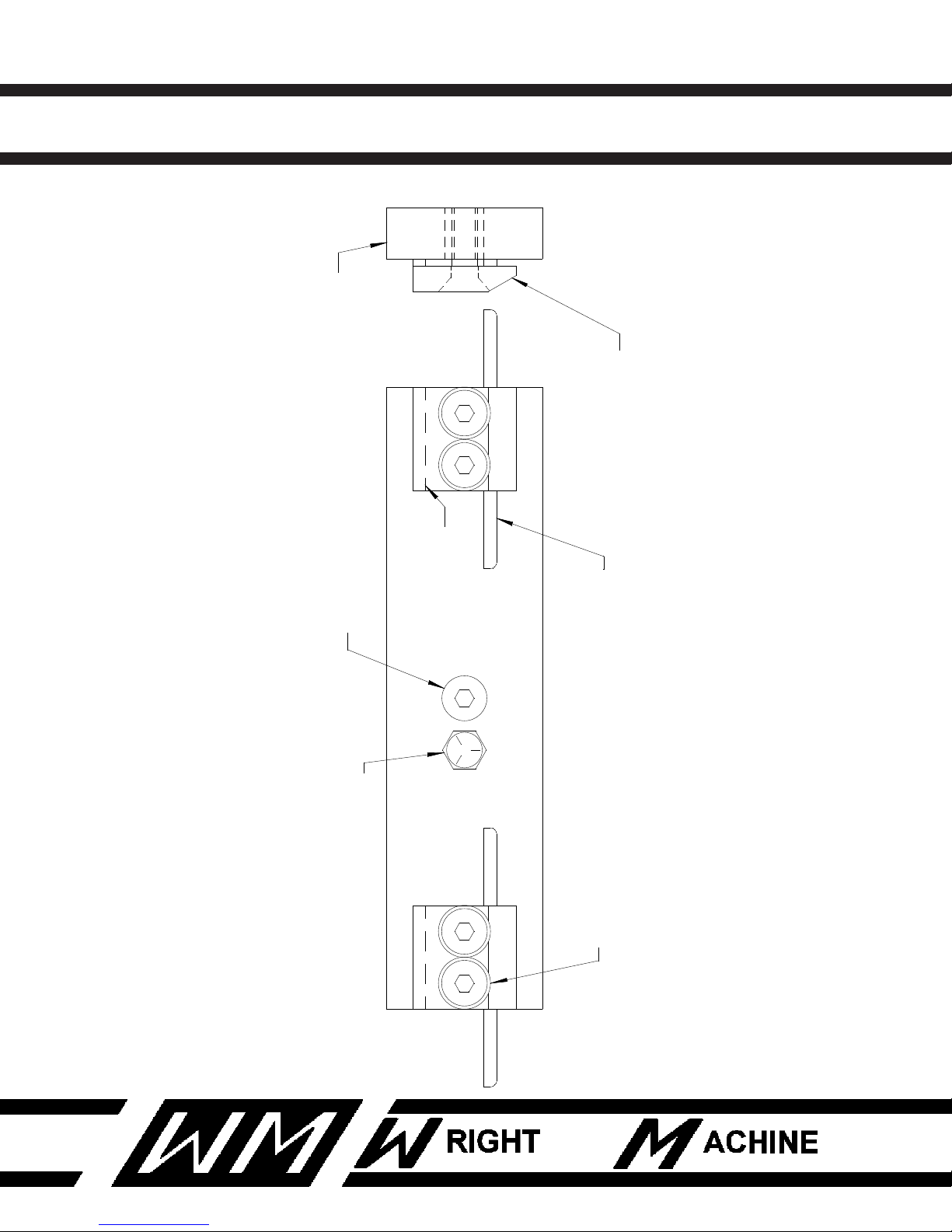
67
F-268
W-2096
F-170
F-316
2 PLCS.
2 PLCS.
8 PLCS.
W-2097
4 PLCS.
W-2231(standard) OR W-2231-1(sliver tooth)
W-2095
2 PLCS.
W-2231
4 PLCS.
4 PLCS.
W-1904-P QUAD DUAL SIDE GRINDER
SAW CARRIER ASSEMBLY
Revised 1-2014
Page 69

W-1904-P QUAD DUAL SIDE GRINDER
INDEX
A
AIR REQUIREMENTS 4
C
COMMON REPLACEMENT PARTS 5
Control Joy Switch 9
CONTROL PANEL 8, 9
CONVERSION CHART 17
COOLANT 6
CRATE SIZE 4
E
68
ear protection 3
ELECTRICAL SCHEMATIC 18, 19, 20, 23
eye protection 3
G
GENERAL SAFETY RULES 3
GRINDING WHEELS 6
L
LIMITED WARRANTY 2
LOADING SAW 13, 14
Load Meter 9
M
MACHINE CONTROLS 12
MAINTENANCE 7
N
Narrow Band Saw Carrier 5
O
Open position 9
OPTIONAL SAW SIZE 4
OPTIONAL VOLTAGE 4
OPTIONS 5
Revised 1-2014
Page 70

W-1904-P QUAD DUAL SIDE GRINDER
INDEX
P
PARTS LIST 25
PRE SET UP 6
R
RADIAL 15
RADIAL ANGLE 15, 16, 17
Run position 9
rust damage 6
S
SAFETY RULES 3
Saw Up / Saw Down 9
SETTING INDEX PITCH 12
SHIPPING WEIGHT 4
Sliver Tooth 5
SPECIFICATIONS 4
SPINDLE MOTORS 4
STANDARD SAW SIZE 4
STANDARD VOLTAGE 4
Stands 5
69
T
TANGENTAL 15
TANGENTAL ANGLE 15, 16, 17
Tooth Counter 9
TOOTH GEOMETRY 15, 16
Totalizer Counter 5
Revised 1-2014
 Loading...