

Wright flow Cocept SQ, SQ1/0004/12, SQ1S, SQ1/0007/06, SQ1L Installation, Operation And Maintanance Manual
...Page 1

I
NSTALLATION,
O
PERATION
A
ND
M
AINTENANCE
M
ANUAL
F
OR THE
R
ANGE OF PUMPS
Page 2

Page 2
INSTALLATION, OPERATION AND MAINTENANCE MANUAL
FOR THE CONCEPT SQ RANGE OF ROTARY LOBE PUMPS
1.0 SAFETY INFORMATION ___________________________________ 4
1.1 R
ISK ASSESSMENT RELATING TO THE USE OF WRIGHT FLOW TECHNOLOGIES
L
IMITED. CONCEPT SQ ROTARY LOBE PUMPS AND PUMP UNITS IN
POTENTIALLY EXPLOSIVE ATMOSPHERES
. ________________________ 7
2.0 INTRODUCTION __________________________________________ 8
2.1 G
ENERAL
______________________________________________ 8
2.2 W
RIGHT FLOW TECHNOLOGIES LIMITED DISTRIBUTORS
_____________ 8
2.3 R
ECEIPT AND STORAGE
____________________________________ 8
2.4 C
LEANING
______________________________________________ 8
2.5 P
UMP MODEL DESIGNATION
_________________________________ 9
2.5.1 ATEX I
NFORMATION PLATE
________________________________ 10
2.5.2 E
QUIPMENT GROUPS & CATEGORIES
_________________________ 10
2.6 P
UMP MODEL AND SERIAL NUMBER
__________________________ 11
2.7 S
TANDARD PUMP COMPONENT TERMS
________________________ 12
3.0 GENERAL ______________________________________________ 13
3.1 C
ONCEPT SQ RANGE PUMPING PRINCIPLE
_____________________ 13
3.2 C
ONCEPT SQ RANGE OPERATING PARAMETERS
_________________ 14
3.3 S
YSTEM DESIGN
________________________________________ 15
3.3.1 S
YSTEM DESIGN AND INSTALLATION
__________________________ 15
3.3.2 I
NSTALLATIONS WITH
CIP/SIP S
YSTEMS
_______________________ 18
3.4 S
TART UP PROCEDURE
___________________________________ 19
3.5 S
HUTDOWN PROCEDURE
__________________________________ 20
3.6 R
OUTINE MAINTENANCE
___________________________________ 20
3.7 H
EATING AND COOLING DEVICES
____________________________ 21
3.8 F
RONT COVER/ROTORCASE JOINT WITH FLUID BARRIER
___________ 23
3.9 R
OTORCASE PORT CONNECTIONS WITH FLUID BARRIER
____________ 24
4.0 CONCEPT SQ DISMANTLING / ASSEMBLY __________________ 25
4.1 SQ1 S
ERIES PUMPS - DISMANTLING
__________________________ 27
4.1.1 F
RONT COVER AND ROTOR REMOVAL
_________________________ 27
4.1.2 C
ARTRIDGE REMOVAL
____________________________________ 28
4.1.3 C
ARTRIDGE DISMANTLING
_________________________________ 29
4.1.3.1 D
RIVE SHAFT CARTRIDGE DISMANTLING
_______________________ 29
4.1.3.2 L
AY SHAFT CARTRIDGE DISMANTLING
_________________________ 29
4.2 SQ1 S
ERIES PUMPS - ASSEMBLY
____________________________ 30
4.2.1 C
ARTRIDGE ASSEMBLY
___________________________________ 30
4.2.1.1 D
RIVE SHAFT CARTRIDGE ASSEMBLY
_________________________ 30
4.2.1.2 L
AY SHAFT CARTRIDGE ASSEMBLY
___________________________ 32
4.2.2 C
ARTRIDGE/MOUNTING PLATE/ROTORCASE ASSEMBLY
____________ 33
4.2.3 S
ETTING ROTOR TIMING
___________________________________ 35
4.2.4 G
EARBOX ASSEMBLY
_____________________________________ 36
4.2.5 R
OTOR ASSEMBLY AND CHECKING CLEARANCES
_________________ 37
4.3 SQ 2, 3, 4 - D
ISMANTLING
_________________________________ 39
4.3.1 F
RONT COVER AND ROTOR REMOVAL
_________________________ 39
Page 3

Page 3
4.3.2 C
ARTRIDGE REMOVAL (AFTER COMPLETING
4.3.1) ________________ 40
4.3.3 C
ARTRIDGE DISMANTLING
_________________________________ 41
4.4 SQ 2, 3, 4 - A
SSEMBLY
___________________________________ 42
4.4.1 C
ARTRIDGE ASSEMBLY
___________________________________ 42
4.4.2 C
ARTRIDGE TO ROTORCASE ASSEMBLY
_______________________ 44
4.4.3 S
ETTING ROTOR TIMING
___________________________________ 46
4.4.4 F
INAL SETTING OF CARTRIDGE ROLLING TORQUE
________________ 47
4.4.5 R
OTOR ASSEMBLY AND SETTING ROTOR CLEARANCES
____________ 48
4.4.6 G
EARBOX COVER ASSEMBLY
_______________________________ 50
4.5 M
ECHANICAL SEAL INSTALLATION AND REMOVAL
_________________ 51
4.5.1 P
ROCEDURES FOR INSTALLING MECHANICAL SEALS
_______________ 51
4.5.2 S
INGLE MECHANICAL SEAL
_________________________________ 52
4.5.3 S
INGLE MECHANICAL SEAL (LOW-PRESSURE FLUSH / QUENCH
). ______ 57
4.5.4 D
OUBLE MECHANICAL SEAL (HIGH-PRESSURE FLUSH
). _____________ 60
4.5.5 M
ECHANICAL SEALS FOR QUENCH OR FLUSH - AUXILIARY SERVICES
___ 63
5.0 SPECIFICATIONS _______________________________________ 66
5.1 C
LEARANCE CHART
______________________________________ 66
5.2 F
IXINGS & TORQUE SETTINGS
______________________________ 67
5.3 L
UBRICANTS
___________________________________________ 68
5.4 M
ATERIAL SPECIFICATION
. _________________________________ 68
5.5 C
ONCEPT SQ RANGE FOUNDATION DIMENSIONS AND WEIGHTS
______ 69
5.6 T
YPICAL BASIC PUMP BUILD
________________________________ 71
5.7 F
AULT FINDING
_________________________________________ 72
5.9 S
ERVICE HISTORY
. ______________________________________ 74
5.10 T
OOL LIST
_____________________________________________ 75
5.11 N
OTES
_______________________________________________ 76
Page 4
Page 4
1.0 Safety Information
INCORRECT INSTALLATION, OPERATION OR MAINTENANCE OF EQUIPMENT
MAY CAUSE SEVERE PERSONAL INJURY AND/OR EQUIPMENT DAMAGE AND
MAY INVALIDATE THE WARRANTY.
THIS INFORMATION MUST BE READ FULLY BEFORE COMMENCING
INSTALLATION, OPERATION OR MAINTENANCE AND MUST BE KEPT WITH
THE PUMP. SUITABLY TRAINED OR QUALIFIED PERSONS MUST UNDERTAKE
ALL INSTALLATION AND MAINTENANCE ONLY.
Safety instructions given in this
manual non-compliance with which
would affect safety are identified by
the symbol:
Safety instructions which shall be
considered for reasons of safe
operation of the pump or pump unit
and/or protection of the pump or
pump unit itself are marked:
DANGER
DO NOT OPERATE PUMP IF:
- THE FRONT COVER IS NOT INSTALLED CORRECTLY.
- ANY GUARDS ARE MISSING OR INCORRECTLY INSTALLED.
- THE SUCTION OR DISCHARGE PIPEWORK IS NOT CONNECTED.
DO NOT PLACE FINGERS ETC INTO THE PUMPING CHAMBER OR ITS
CONNECTION PORTS OR INTO ANY PART OF THE GEARBOX IF THERE
IS ANY POSSIBILITY OF THE PUMP SHAFTS BEING ROTATED. SEVERE
INJURY WILL OCCUR.
DO NOT exceed the pumps rated pressure, speed, and temperature, or
change the system/duty parameters from those for which the pump was
originally supplied, without confirming its suitability for the new duty. Running of
the pump outside of its operation envelope can cause mechanical contact in
the pump head, excessive heat and can represent a serious risk to health and
safety.
Installation and operation of the pump must always comply with health and
safety regulations.
A device must be incorporated into the system or drive to prevent the pump
exceeding its stated duty pressure. It must be suitable for both directions of
pump rotation where applicable. Do not allow pump to operate with a
closed/blocked discharge unless a pressure relief device is incorporated.
WWAARRNNIINNGG
WWAARRNNIINNGG
Page 5
Page 5
The mounting of the pump or pump unit should be solid and stable. Pump
orientation must be considered in relation to drainage requirements. Once
mounted, shaft drive elements must be checked for correct alignment. Rotate
pump shaft by at least one full revolution to ensure smoothness of operation.
Incorrect alignment will produce excessive loading and will create high
temperatures and increased noise emissions. It may also be necessary to
earth the pump to avoid the build up of a potential charge difference that could
cause a spark
The installation must allow safe routine maintenance and inspection (to
replenish lubricants, check for leakage, monitor pressures, etc) and provide
adequate ventilation necessary to prevent overheating.
Fill with the recommended grades and quantities of lubricant see section 3.4.
Beware of over/under filling the gearbox as this could cause the pump to
overheat and mechanical damage to occur.
Before operating the pump, ensure that it and all parts of the system to which it
is connected are clean and free from debris and that all valves in the suction
and discharge pipelines are fully opened. Ensure that all pipe work connecting
to the pump is fully supported and aligned with its relevant connections.
Misalignment and/or excess loads will cause severe pump damage. This could
result in unexpected mechanical contact in the pump head and has the
potential to be a source of ignition.
Ensure that pump rotation is correct for the desired direction of flow; (see
section 3.4)
Do not install the pump into a system where it will run dry (i.e. without a supply
of pumped media) unless it is equipped with a flushed shaft seal arrangement
complete with a fully operational flushing system. Mechanical seals require a
thin fluid film to lubricate the seal faces. Dry running can cause excessive heat
and seal failure.
Install pressure gauges/sensors next to the pump suction and discharge
connections to monitor pressures.
Caution must be taken when lifting the pump. Suitable lifting devices should be
used as appropriate. If pump is baseplate mounted, the base plate must be
used for all lifting purposes, not any part of the pump. If slings are used for
lifting, they must be safely and securely attached. For weights of bare shaft
pumps refer to section 5.5.
DO NOT attempt any maintenance or disassembly of the pump or pump unit
without first ensuring that:
- The pump is fully isolated from the power source (electric, hydraulic,
pneumatic).
- The pumping chamber and any shaft seal support system, front cover
barrier support system, and rotorcase port barrier support system are
de-pressurised and purged.
- Any temperature control devices (jackets, heat-tracing, etc) are fully
isolated, that they are de-pressurised and purged, and components
allowed to reach a safe handling temperature.
DO NOT loosen or undo the front cover, any connections to the pump, shaft
WWAARRNNIINNGG
WWAARRNNIINNGG
WWAARRNNIINNGG
WWAARRNNIINNGG
WWAARRNNIINNGG
Page 6
Page 6
seal housings, barrier support systems, temperature control devices, or other
components, until sure that such action will not allow the unsafe escape of any
pressurised media.
Pumps and/or drives can produce sound pressure levels exceeding 85-dB (A)
under certain operating conditions. When necessary, personal protection
against noise must be taken. See section 5.8 for typical noise emission data.
Avoid any contact with hot parts of pumps and/or drives, which may cause
injury. Certain operating conditions, temperature control devices (jackets, heattracing, etc), bad installation, or poor maintenance can all promote high
temperatures on pumps and/or drives.
When cleaning, either manually or by CIP method, the operator must ensure
that a suitable procedure is used in accordance with the system requirements.
For CIP cleaning requirements, refer to section 3.3.2. The exterior of the pump
should be cleaned periodically.
Surface temperature of pump is also dependent on the temperature of
pumped medium.
WWAARRNNIINNGG
Page 7

Page 7
1.1 Risk assessment relating to the use of Wright Flow Technologies
Limited. Concept SQ rotary lobe pumps and pump units in potentially
explosive atmospheres.
Source Of Hazards Potential Hazards
Frequency Of
Hazards
Recommended Measures
Unvented cavities Build up of explosive gas
Very Rare
Ensure that pump is totally filled.
Consider mounting ports vertically.
See Chapter 1.0
Rotorcase / Rotors / Front
Cover
Unintended mechanical
contact
Rare
Ensure that operating pressures are
not exceeded. Ensure that suffcient
NPSH to prevent cavitation.
See
Chapter 1.0 / 3.3.1
Service plan.
Pump external surfaces
excess temperature.
Electrostatic charging
Rare
User must ensure temperature limits.
Do not overfill gearboxes with
lubricant. Provide a ground contact
for pump.
See Chapter 1.0 /
Service
plan.
Cover 'O' ring
Pump liquid leakage. Build
up of explosive gas.
Very Rare
Check selection of elastomers are
suitable for application. Ensure cover
retaining nuts are tight. Service plan.
Pump casing / cover
Pump liquid leakage. Build
up of explosive gas.
Very Rare
Stainless steel, Corrosion resistant.
Shaft seals
excess temperature.
Unintended mechanical
contact.
Leakage.
Build up of explosive gas.
Rare
Selection of seal system must be
suitable for application.
See Chapter
1.0 / 4.5
. Service plan. Seals must
never run dry.
Auxiliary system for shaft
sealing
Pump liquid leakage. Build
up of explosive gas.
Rare
Selection of auxiliary seal system
must be suitable for application.
Seals must never run dry.
Rotation direction test Excess temperature
Very Rare
If flushed seals are installed ensure
that flush is applied to seal
assemblys. Only allow pump to run
for minimum period - just a few
seconds.
Closed valve condition
Excess Temperature.
Excess Pressure.
Mechanical contact.
Rare
Can cause excessive pressue, heat
and mechanical contact.
See
Chapter 1.0
Shaft Random induced current
Very Rare
Provide a ground contact for pump.
See Chapter 1.0.
Mechanical shaft coupling
(Torque Protection)
Temperature from friction
Sparks from break up of
shear pins.
Electrostatic charging
Rare
Coupling selection must suit
application.
See Chapter 1.0.
Mechanical shaft coupling
(standard)
Break up of spider.
Unintended mechanical
contact.
Electrostatic charging
Rare
Coupling selection must suit
application. Service plan.
See
Chapter 1.0.
Note:
- For a feature to be suitable for an applic
ation, The feature must be fit for its
designated purpose and also suitable for the environment where it is to be installed.
Page 8

Page 8
2.0 Introduction
2.1 General
The range of Concept SQ rotary lobe pumps are manufactured and distributed,
refer to section 2.2, by Wright Flow Technologies Limited, Eastbourne,
England.
This manual includes all the necessary information for the Concept SQ pump
range and should be read prior to commencing installation, operation or
maintenance.
When asking for assistance please quote the pump model and serial number.
This information can be obtained from the pump nameplate which is located on
the top of the pump gearbox cover, refer to section 2.6.
Should the nameplate be unreadable or missing, the pump serial number is
also stamped on the rear face of the rotorcase, refer to section 2.6, Figs 2 & 3.
If it is proposed to modify the system or change the characteristics of the
product to be pumped from that for which the pump was originally selected,
Wright Flow Technologies Limited or their authorised distributor should be
consulted.
2.2 Wright Flow Technologies Limited Distributors
Wright Flow Technologies Limited distributes their products internationally via a
network of authorised distributors. Throughout this manual where reference is
made to Wright Flow Technologies Limited, any authorised distributor will also
provide service and assistance. Should you require any additional information
regarding the Concept SQ range of pumps contact Wright Flow Technologies
Limited or their local authorised distributor.
2.3 Receipt and Storage
On receipt of the pump, immediately examine for any signs of visible damage.
If any damage is noted, contact Wright Flow Technologies Limited and clearly
mark upon the carriers paperwork that the goods have been received in a
damaged condition, with brief description of damage.
If the pump is not required for immediate installation then it should be stored
within a suitable environment.
2.4 Cleaning
The Concept SQ pump range is suitable for manual cleaning, CIP (Cleaning In
Place) and SIP (Sterilisation In Place) refer to section 3.3.2.
The mechanical seals are mounted directly behind the rotor and are designed
and to minimise product entrapment and maximise the effects of cleaning.
This strategic positioning of the mechanical seals, combined with their ease of
access provides an arrangement that can be more effectively cleaned by both
manual and CIP/SIP procedures.
Page 9
Page 9
It is recommended that the exterior of the pump be cleaned periodically.
2.5 Pump Model Designation
The designation of pump models in the Concept SQ range is as follows: -
SQ1/0004/12 (SQ1S)
SQ1/0007/06 (SQ1L)
SQ2/0017/15 (SQ2S)
SQ2/0030/07 (SQ2L)
SQ3/0054/15 (SQ3S)
SQ3/0103/07 (SQ3L)
SQ4/0160/15 (SQ4S)
SQ4/0303/07 (SQ4L)
This, together with the pump serial number, should be quoted when requesting
additional information on the pump or when ordering spare parts. The pump
serial number is stamped on the pump nameplate and the rear face of the
rotorcase, refer to section 2.6, Figs 2 and 3.
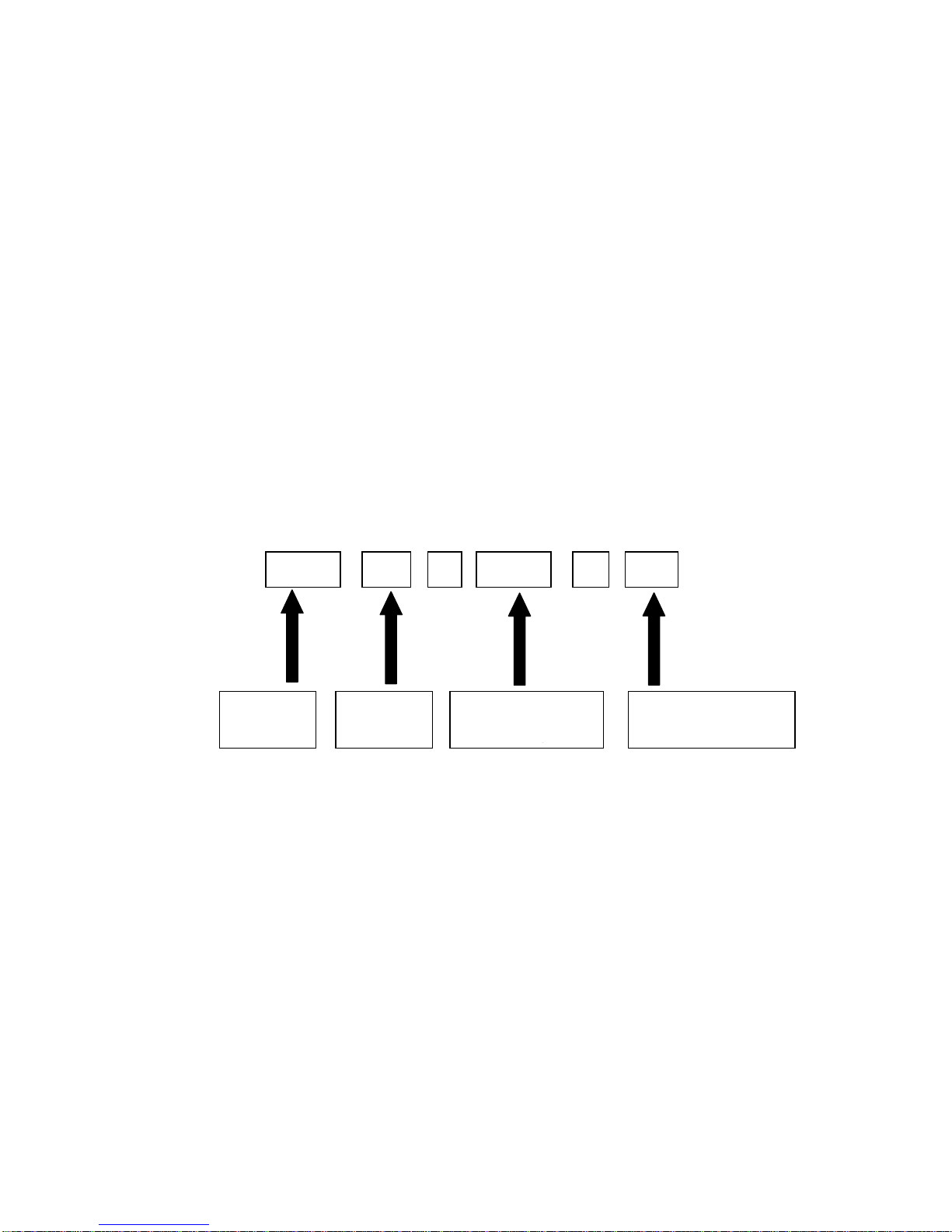
For an explanation of pump model designations see Fig 1.
For the maximum operating pressures, temperatures and speeds refer to
section 3.2, Fig 6.
Fig 1 (European Designation)
SQ 3 0054 15 / /
P
UMP
M
ODEL
D
ISPLACEMENT
(L
TRS/REV X
M
ODEL
S
IZE
MAX. P
RESSURE
(BAR)
Page 10
Page 10
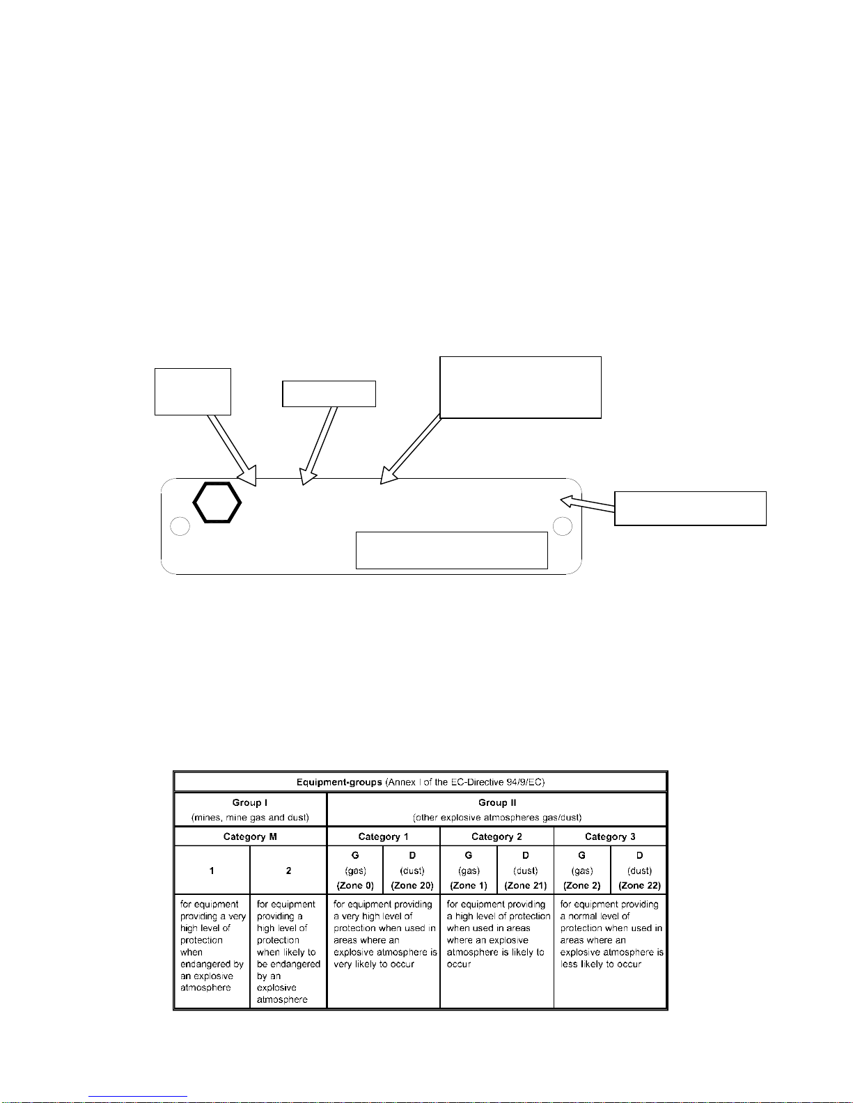
2.5.1 ATEX Information
ATEX Pump Requirements
Please be aware that mechanical seals are a source of heat and must never be
allowed to run dry. We would recommend provision be made to ensure that there is a
flow of fluid around the pump seals at all times. If there is a risk of the supply being
interrupted, we would recommend that the flush on the seals be fitted with a flow
detection device. The surface temperature of the pump is dependent on the
temperature of the pumped fluid and due account of this should be taken whilst
undertaking your risk assessment of the installation. These pumps are rated to T3.
2.5.2 Equipment Groups & Categories
TEMP - T3
SERIAL NO:
ex
II - 2 - G/D
Group
II.
Category 2
Unit is suitable for
environments
containing dust or gas
Temperature Class.
Page 11
Page 11
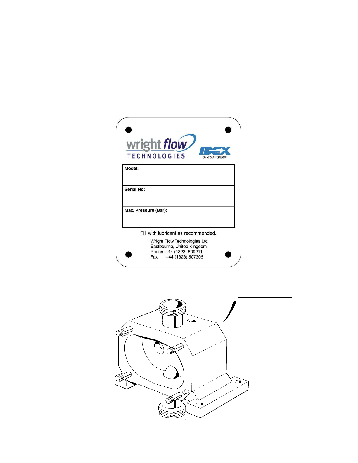
2.6 Pump Model and Serial Number
Should you require any information regarding your Concept SQ rotary lobe
pump contact Wright Flow Technologies Limited quoting the pump model and
serial number as stated on the pump nameplate, see Fig 2, which is fixed to
the pump gearbox cover,
Should this be damaged or missing, the pump serial number is also stamped
on the rear face of the rotorcase, see Fig 3.
Fig 2
Fig 3
12345 / A / 99
Page 12
Page 12
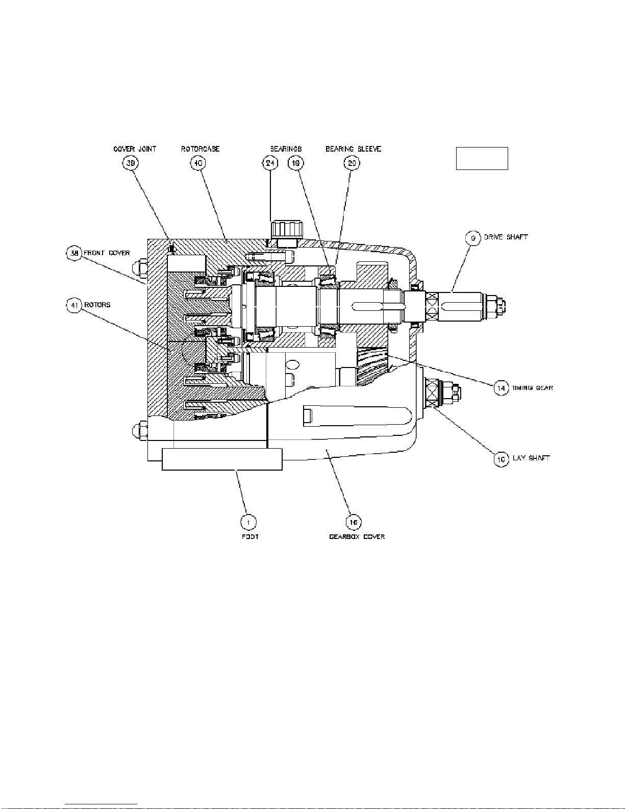
2.7 Standard Pump Component Terms
Fig 4
Page 13
Page 13
3.0 General
3.1 Concept SQ Range Pumping Principle
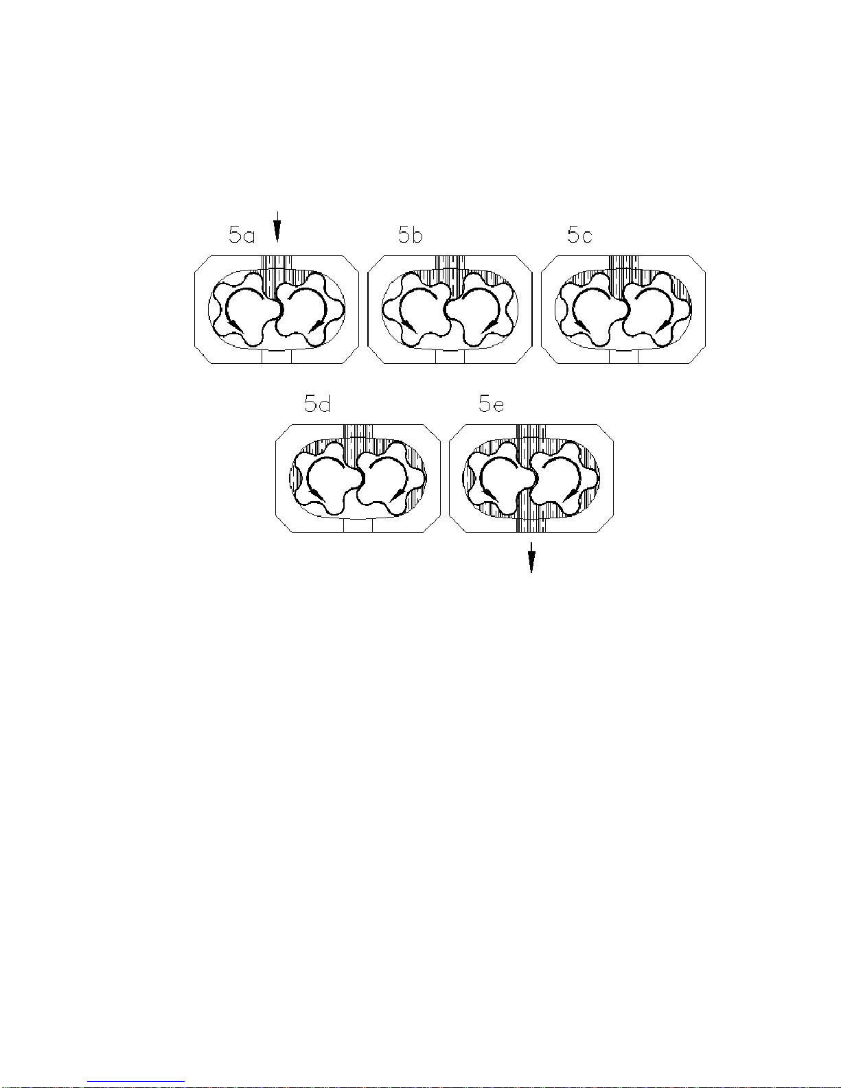
see Fig 5
Fig 5
The pumping action of the rotary lobe pump principle is generated by the
contra-rotation of two pumping elements (rotors) within a chamber (rotorcase),
see Fig 5. The rotors are located on shafts, which in turn are held within two
cartridge assemblies. The shaft cartridge assemblies comprise the shaft
support bearings and the timing gears. The timing gears transfer the drive from
the driven shaft to the lay shaft, synchronising the rotors such that they rotate
without contact with each other.
As the rotors pass the suction port, see Fig 5a, the cavity generated increases
creating a pressure decrease, which induces the media to be pumped to flow
into the rotorcase.
The pumped media is carried around the rotorcase by the rotors, see Fig 5b
and 5c, to the discharge side of the pump, Fig 5d. Here the cavity decreases
and the pumped medium is discharged from the rotorcase, Fig 5e.
For pump component terms see Fig 4.
Page 14

Page 14
3.2 Concept SQ Range Operating Parameters
Fig 6
Concept SQ
Model
D
ISPLACEMENT
C
ONNECTION SIZE
(International
Standards)
D
IFFERENTIAL
P
RESSURE
(Maximum)
M
AXIMUM
S
PEED
(Continuous)
M
AXIMUM
T
EMPERATURE
(Continuous)
litres / rev
I gal /
100 rev
US gal /
100 rev
mm Inches Bar
lbf/in² rev / min
°C
°F
SQ1/0004/12 0.04 0.88 1.06
25
1.0
12
175
1000
150 300
SQ1/0007/06 0.07 1.76 2.11
25
1.0
6
85
1000
150 300
SQ2/0017/15 0.17 3.74 4.49
40
1.5
15
215
850
150 300
SQ2/0030/07 0.30 6.60 7.93
50
2.0
7
100
850
150 300
SQ3/0054/15 0.54 11.88 14.27
50
2.0
15
215
700
150 300
SQ3/0103/07 1.03 22.66 27.21
80
3.0
7
100
700
150 300
SQ4/0160/15 1.60 35.20 42.27
80
3.0
15
215
600
150 300
SQ4/0303/07 3.03 66.66 80.06 100
4.0
7
100
600
150 300
The maximum pressure and speed operating parameters are given in Fig 6. In
practice these may be limited due to the nature of the product to be pumped
and/or design of the system in which the pump is to be installed and / or the
process.
If it is proposed to modify the system/duty, or change the characteristics of the
product to be pumped from that for which the pump was originally selected
Wright Flow Technologies Limited should be consulted.
The pump should not be subjected to sudden temperature changes to avoid
the risk of damage through expansion/contraction of components. Care should
be taken when selecting pumps for handling liquids containing abrasive
particles as these may cause wear of pump head components, for advice and
assistance contact Wright Flow Technologies Limited.
WWAARRNNIINNGG
Page 15

Page 15
3.3 System Design
3.3.1 System Design and Installation
When incorporating any pump into a system it is considered good
practice to minimise pipework runs and the number of pipe fittings (tees,
unions, bends etc.) and restrictions. Particular care should be taken in
designing the suction line, which should be as short and straight as
possible with the minimum of pipefittings to minimise restricting product
flow to the pump. The following should be considered at the design
stage of any system.
a) Ensure ample room is provided around the pump to allow for: -
ii) Access to the pump and drive for routine inspection and
maintenance, for example to replenish pump or drive
lubricant, remove pump front cover and rotors.
iii) Ventilation of the drive to prevent over heating.
b) The pump must not be used to support pipework; all pipework to
and from the pump unit must be independently supported. Failure
to observe this may cause distortion of the pump head
components or assembly and serious consequential damage to
the pump.
c) Valves should be provided adjacent to the pump suction and
discharge connections to allow the pump to be isolated from the
system for routine inspection and maintenance.
d) Rotary lobe pumps are of the positive displacement type and
therefore an overload protection device must be provided. This
can take the form of:i) An in-line pressure relief system, i.e. external to the pump.
ii) Inclusion of a torque limiting device in the drive system.
iii) Rupture disc incorporated in the discharge pipework.
e) Where pump rotation and hence flow is to be reversed during
normal operation the overload device must be capable of
protection for both directions of rotation/flow.
f) It is considered good practice to ensure all pipework and
associated plant from the suction vessel to the discharge point is
thoroughly cleaned before installation of the pump to avoid the
possibility of debris entering the pump and causing damage.
g) Pressure gauges should be installed adjacent to the pump suction
and discharge connections such that system pressures can be
monitored. These gauges will provide a clear indication of
changes in operating conditions and where a relief valve is
incorporated in the system, will be necessary for setting and
checking the functioning of the valve.
WWAARRNNIINNGG
WWAARRNNIINNGG
WWAARRNNIINNGG
Page 16
Page 16
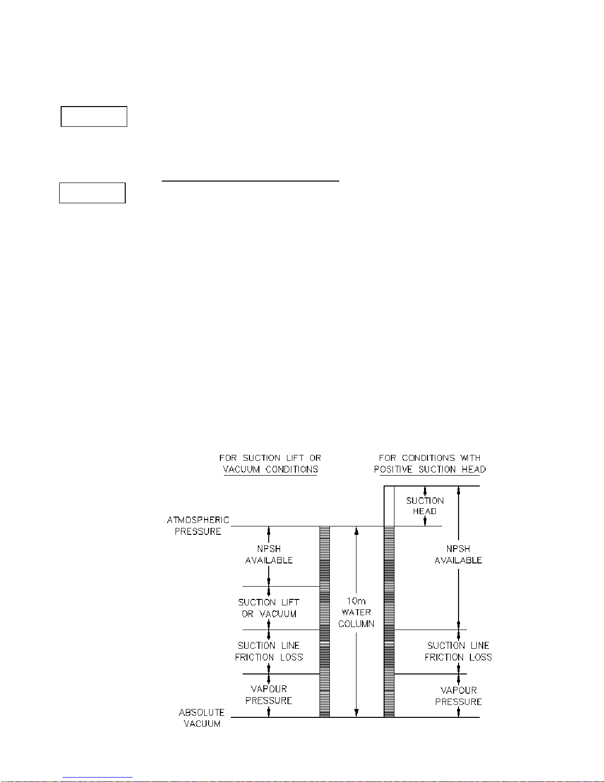
h) Suction Conditions
It is imperative that the suction condition at the pump inlet meets
the Net Positive Suction Head Required (NPSHR) by the pump.
Failure to observe this could cause cavitation, resulting in noisy
operation, reduction in flow rate and mechanical damage to the
pump and associated equipment.
The Net Positive Suction Head Available (NPSHA) from the system
must always exceed the Net Positive Suction Head Required (NPSHR)
by the pump. Observing the following general guidelines should ensure
the best possible suction condition is created.
- Suction pipework is at least the same diameter as the pump
connections.
- Suction pipework is straight for a distance of at least the
equivalent of 10 pipe diameters immediately before pump.
- The length of suction pipework is kept to the absolute minimum.
- The minimum number of bends, tees and pipework restrictions
are used.
- That calculations to determine system NPSHA are carried out for
the worst condition, see Fig 7.
- Should advice on pump or system NPSH characteristics be
required contact Wright Flow Technologies Limited.
Fig 7
WWAARRNNIINNGG
WWAARRNNIINNGG
Page 17
Page 17
i) When installing a pump complete with baseplate, motor and drive
the following guidelines must be observed:
- The preferred drive arrangement for any rotary lobe pump
is in-line direct coupled. If an alternative is required please
contact Wright Flow Technologies Limited.
- Flexible couplings must always be incorporated and
correctly aligned. To check coupling alignment rotate the
shaft by at least one full revolution and ensure that the
shaft rotates smoothly.
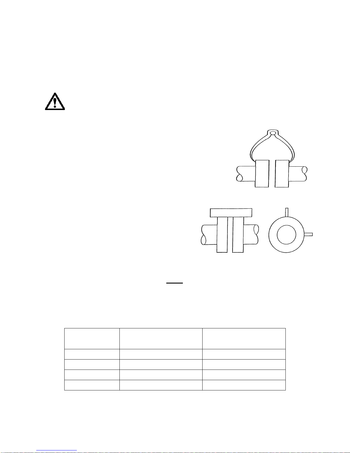
Fig 8
To check for and correct angular misalignment, use
a calliper to check the measurement across the
hubs. Adjust position of pump or drive as
necessary until the measurement is the same at all
points around the hubs.
Fig 9
To check for and correct parallel
offset, place a straightedge across the
hub flanges in two positions at 90
Degrees to each other. Adjust
position of pump or drive as
necessary until the straightedge lays
flat on both sides.
Note:
Some couplings are able to withstand gross angular and/or parallel
misalignment. However, the above methods of reduce these effect to an
absolute minimum is required to avoid placing excessive loads onto
pump and/or drive components. The table below gives details of
maximum parallel and angular misalignments allowed.
C
ONCEPT SQ
M
ODEL
M
AXIMUM PARALLEL
M
ISALIGNMENT (MM
).
M
AXIMUM ANGULAR
M
ISALIGNMENT (DEGREES
)
SQ1 0.05 0.5
SQ2 0.075 0.5
SQ3 0.10 1.0
SQ4 0.15 1.0
Couplings of a non-flexible design must never be used.
Page 18
Page 18
- Couplings must always be enclosed in a suitable guard to prevent
contact with rotating parts, which could result in personal injury.
Guards should be of suitable material, see below and of
sufficiently rigid design to prevent contact with rotating parts
under normal operating conditions.
Note: The guard must be designed such that it fully covers the
projecting part of the lay shaft of the pump.
- When installing pump sets in flammable or explosive
environments, or for handling flammable or explosive materials.
Special consideration must be given to the safety aspects of the
drive unit enclosure and also to the materials used for both the
coupling and the guard to eliminate the risk of producing sparks.
- Baseplates must be secured to a flat level surface such that
distortion and misalignment are avoided. Once baseplates are
fastened in position the drive alignment must be re-checked.
- When using electric motor drives ensure that the electrical supply
is compatible with the drive and controls and that the method of
wiring is correct for the type of starting required by the motor i.e.
Direct On Line, Star Delta etc. Ensure all components are
correctly earthed.
3.3.2 Installations with CIP/SIP Systems
The Concept SQ pump range has been designed to be effectively
cleaned by the CIP procedures recommended for in place cleaning of
process plant. To assist in maximising the effectiveness of cleaning
within the pump head it is recommended that during the cleaning cycle a
flow rate equivalent to a velocity of 1.5 metres per second; in a pipe of
equal diameter to the rotorcase connections is achieved. With a
differential pressure of 2 to 3 bar being developed across the pump
head.
For applications where maximum drainage of the pump head is required,
for example in the handling of ‘Agri-Foodstuffs’ and / or where CIP is
employed, the pump should be mounted with the rotorcase connections
in the vertical orientation. A procedure must be determined to ensure
that the pump is effectively cleaned. It is recommended that this cycle
would typically include a combination of some or all of the following:
Acidic or Caustic based Detergents, ‘Sanitisers’, Disinfectants and
Water rinses. These must be appropriate to both the products being
handled and the materials of construction of the pump.
The Concept SQ pump range is also suitable for SIP treatment.
WWAARRNNIINNGG
Page 19
Page 19
3.4 Start Up Procedure
- Check all pipework and associated equipment is clean and free
from debris and that pipe connections are secure and leak free.
- For pumps installed with flushed mechanical seals check all
auxiliary services are in place and connected and provide
sufficient flow and pressure for flushing purposes, refer to section
4.5.7.
- For pumps installed with Fluid Barrier devices on Front Cover /
Rotorcase joint and Rotorcase port connections, check all
auxiliary services are in place and connected and provide
sufficient flow and pressure, refer to sections 3.8 and 3.9.
- Ensure lubrication is provided for both pump and drive. Concept
SQ pumps are despatched without oil and should be filled to the
level of the oil sight glass which must be installed in the upper
tapped hole in the side of the gearbox cover, refer to section 5.3
for pump oil capacities and grades.
- Check that, if an external relief valve is incorporated in the
system, it is set correctly. For commissioning purposes it is
considered good practice to set the relief valve lower than the
system design pressure. On completion of commissioning the
relief valve should be reset to the required setting for the
application. The required setting should never exceed the lower
of either the pumps maximum pressure rating or the system
design pressure.
- Ensure both suction and discharge valves are fully open, and
pipework is free from all obstructions. Concept SQ pumps are of
the positive displacement type and should therefore never be
operated against a closed valve as this would result in pressure
overload, resulting in damage to the pump and possibly the
system.
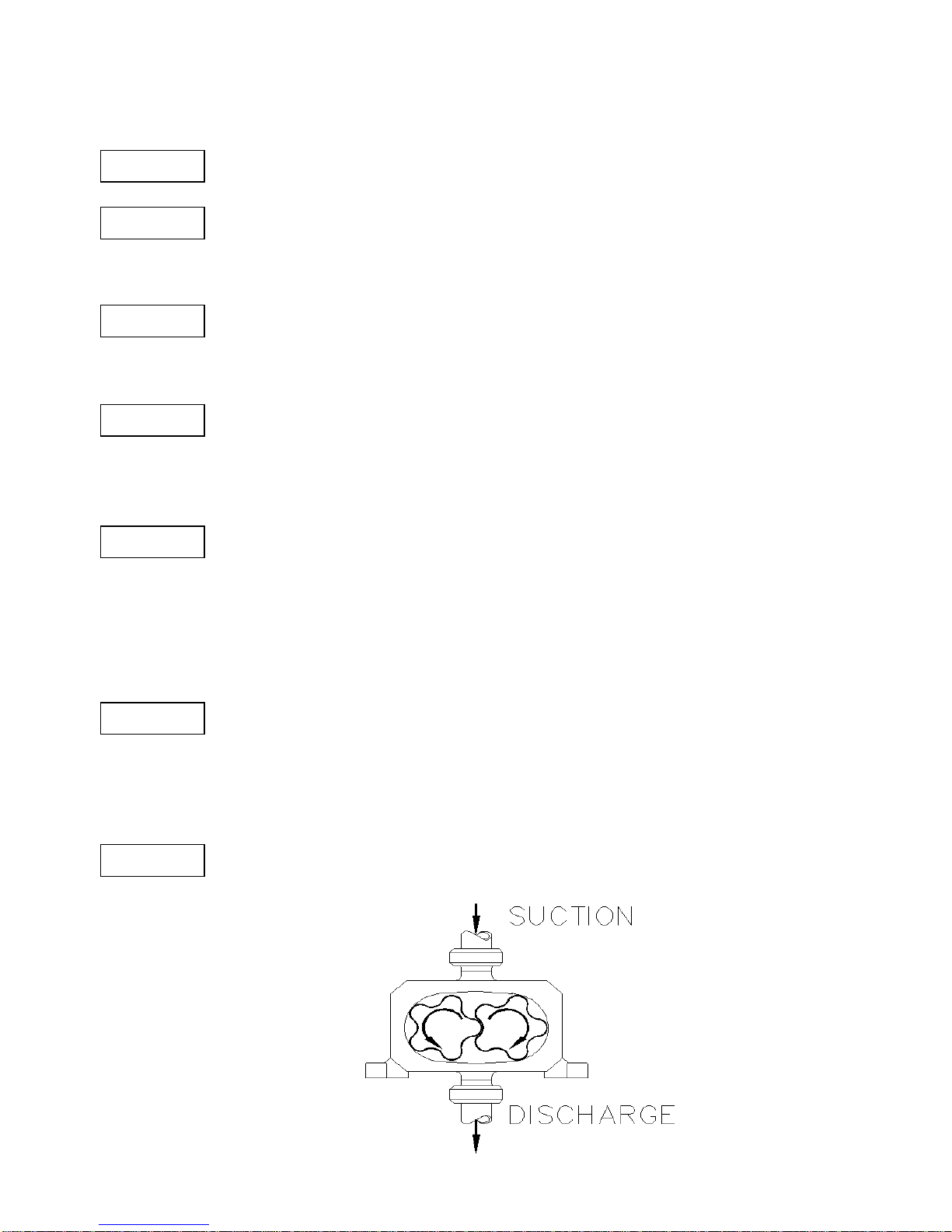
- Ensure rotation of the drive shaft is correct for the direction of flow
required (see Fig 10).
Fig 10
WWAARRNNIINNGG
WWAARRNNIINNGG
WWAARRNNIINNGG
WWAARRNNIINNGG
WWAARRNNIINNGG
WWAARRNNIINNGG
WWAARRNNIINNGG
Page 20

Page 20
- Ensure product is available in the suction vessel before starting
pump, this is very important for pumps installed with single
mechanical seals not being serviced with a quench or flush as
these sealing arrangements must never be allowed to run dry.
- Before commencing operation it is considered good practice to
momentarily start/stop the pump to check the direction of rotation
and ensure that the pump is free of obstructions. Once this has
been carried out commence operation keeping a visual check on
suction and discharge pressure gauges and monitor pump
temperature and power absorbed where possible.
3.5 Shutdown Procedure
When shutting the pump down, close both the suction and discharge valves
and ensure that the necessary safety precautions are taken: -
- The prime mover power source has been isolated.
- That, where employed, mechanical seal flush, rotorcase port
connection barrier flush and front cover barrier flush auxiliary
services have been isolated, de-pressurised and fully drained.
- That, where employed, heating / cooling devices have been
isolated, de-pressurised and fully drained.
- Pump head and pipework have been drained and purged.
3.6 Routine Maintenance
- Check mechanical shaft seals for leakage.
- Check oil levels regularly.
- Change the oil every 12 months or 3000 operating hours
whichever is the sooner. For lubricant capacities and grades refer
to section 5.3.
WWAARRNNIINNGG
WWAARRNNIINNGG
Page 21
Page 21
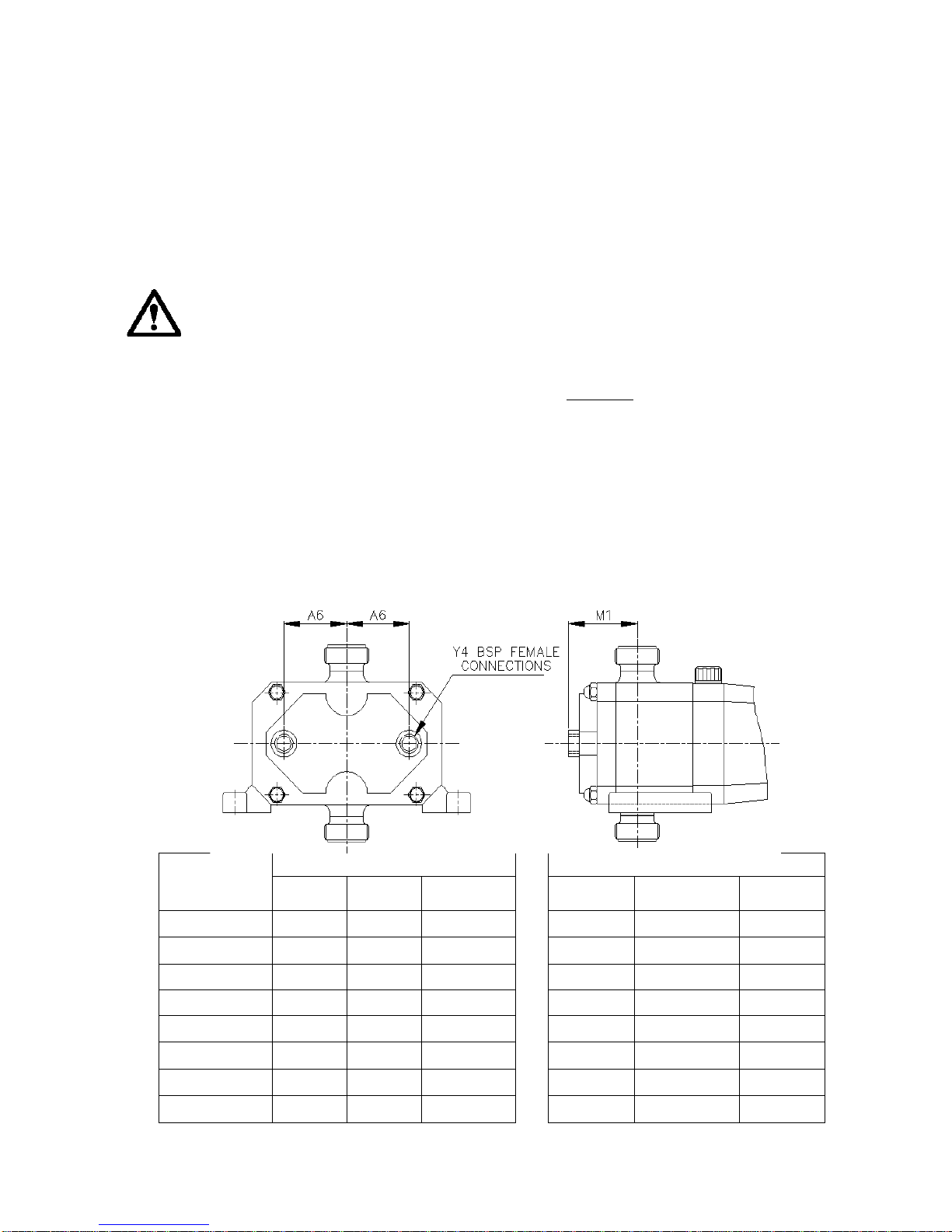
3.7 Heating and Cooling Devices
See Figs 11 & 12
All models in the Concept SQ range can be supplied with a jacketed
front cover and, with the exception of the SQ1 series pumps, rotorcase
with ports for circulation of a heating/cooling media. The jacketed cover
and rotorcase heating and cooling ports are strategically positioned such
that the thermal effect acts on the pump chamber and seal area.
The pressure rating of the Concept SQ range jacketed front cover and
rotorcase heating/cooling ports is 3.5 bar g
(50 PSI)
and this should not
be exceeded without first making reference to Wright Flow Technologies
Limited.
Heating/cooling of the pump head is used to maintain, rather than
increase/decrease, the temperature of the pumped media and should be
used as part of a complete system where suction and discharge lines
and vessels are also heated/cooled.
Where heating/cooling devices are employed the heating/cooling media
should be circulated 15-20 minutes prior to pump start-up and also for a
similar period of time after the pump has been shutdown. Where a CIP
or SIP cycle is employed as part of the process, the heating/cooling
media should continue to be circulated during the cleaning cycle.
Fig 11 Dimensions of Front Cover Jacket for Heating/Cooling
Concept SQ
Model
Millimetres Inches
A6 M1
Y4
(Inches)
A6 M1 Y4
SQ1/0004/12 38.0 58.0 ¼ 1.50 2.28 ¼
SQ1/0007/06 38.0 60.5 ¼ 1.50 2.38 ¼
SQ2/0017/15 54.0 77.5 ½ 2.13 3.05 ½
SQ2/0030/07 54.0 82.0 ½ 2.13 3.23 ½
SQ3/0054/15 90.0 101.0 ½ 3.54 3.98 ½
SQ3/0103/07 90.0 110.0 ½ 3.54 4.33 ½
SQ4/0160/15 142.5 120.0 ½ 5.61 4.72 ½
SQ4/0303/07 142.5 140.0 ½ 5.61 5.51 ½
Note:
For all other dimensions see section 5.5, Foundation Dimensions
Page 22
Page 22
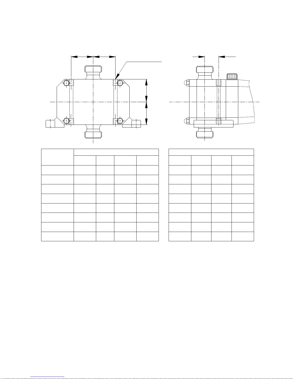
Fig 12 Dimensions for Rotorcase Ports for Heating/Cooling
Concept SQ
Model
Millimetres Inches
A7 BF M2
Y5
(Inches)
A7 BF M2 Y5
SQ1/0004/12 N/A N/A N/A N/A N/A N/A N/A N/A
SQ1/0007/06 N/A N/A N/A N/A N/A N/A N/A N/A
SQ2/0017/15 80 66.5 14 1/8 3.15 2.62 0.55 1/8
SQ2/0030/07 80 66.5 36 1/8 3.15 2.62 1.42 1/8
SQ3/0054/15 102.5 90.5 16 1/8 4.04 3.56 0.63 1/8
SQ3/0103/07 102.5 90.5 49 1/8 4.04 3.56 1.93 1/8
SQ4/0160/15 140 137 22 1/8 5.51 5.39 0.87 1/8
SQ4/0303/07 140 137 64 1/8 5.51 5.39 2.52 1/8
Note: For all other dimensions see section 5.5, Foundation Dimensions and Weights.
Y4 BSP Female
Connections
M2
A7
A7
Page 23
Page 23
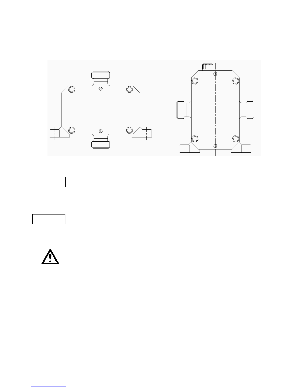
3.8 Front Cover/Rotorcase Joint with Fluid Barrier
Fig 13
The product to atmosphere interface between front cover and rotorcase can be
provided with a fluid barrier to prevent either the ingress of microbiological and
other contaminants, or the egress of pumped media to atmosphere. The fluid
must be compatible with the media being pumped and the materials of
construction of any pump components with which it comes into contact.
Where pumps are equipped with this feature, two tapped holes are located in
the front cover forming the connections for the supply of the barrier fluid, see
fig 13. The position of the holes is dependant upon the orientation of the pump,
but in either case, the lower tapped hole must be used for the fluid inlet so that
air is naturally vented out via the upper tapped hole. Barrier liquids should be
supplied at a flow rate of approximately 0.5 to 1 litres per minute. Barrier
gasses can be either static or flowing as applicable.
The pressure rating of the Concept SQ range front cover / rotorcase joint with
fluid barrier is 3.0 bar g (43.5 PSI) and this should not be exceeded without first
making reference to Wright Flow Technologies Limited.
The position of the holes is dependent upon the orientation of the pump.
WWAARRNNIINNGG
WWAARRNNIINNGG
Page 24
Page 24
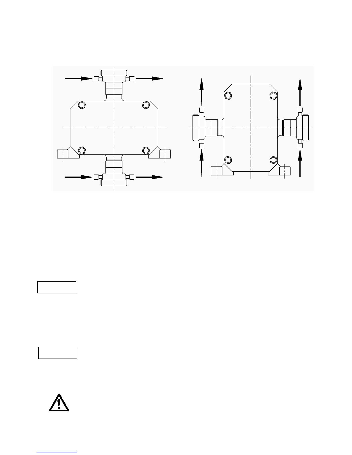
3.9 Rotorcase Port Connections with Fluid Barrier
Fig 14
The product to atmosphere interface between the rotorcase port connections
and the suction and discharge pipework can be provided with a fluid barrier to
prevent either the ingress of microbiological and other contaminants, or the
egress of pumped media to atmosphere, when the applicable port connections
are installed.
Where pumps are equipped with this feature, two tapped holes are located on
each of the connection male parts which are welded to the rotorcase forming
the connections for the supply of the barrier fluid, see Fig 14.
In the standard orientation, which is with the rotorcase ports in the vertical
plane, either tapped hole can be used as the fluid inlet. If the barrier media is a
liquid, the flow should be raised to approximately 2 litres per minute for the first
few minutes to allow venting of any gas or air trapped in the barrier chamber of
the lower connection assembly. The flow can then be reduced to zero if
required, or maintained at a value between 0 and 1 litres per minute. If the
barrier media is a gas, it should be made to flow for the first few minutes to
allow removal of air, and then the flow can be reduced to zero if required.
In the optional orientation, which is with the connection ports in the horizontal
plane, the lower tapped hole should be used for the fluid inlet so that air or gas
trapped in the barrier chambers is naturally vented out via the upper tapped
hole. If the barrier media is a liquid, the flow should be raised to approximately
2 litres per minute for the first few minutes to allow venting of any air or gas.
The flow can then be reduced to zero if required, or maintained at a value
between 0 and 1 litres per minute. If the barrier media is a gas, it should be
made to flow for the first few minutes to allow removal of air, and then the flow
can be reduced to zero if required
The pressure rating for the fluid barrier of these port connections is 3.0 Bar g
(43.5 PSI) and this must not be exceeded under any circumstances.
WWAARRNNIINNGG
WWAARRNNIINNGG
Page 25
Page 25
4.0 Concept SQ Dismantling / Assembly
Before undertaking any work on the pump the recommended Shutdown
Procedure should be followed, refer to section 3.5.
Certain components of the pump are only usable once. It is essential to be
certain that new replacement components are available for re-assembly. These
are the split pins used to secure the castellated nuts, and the o-rings located
between the rotors and shafts.
Whilst dismantling or assembling the pump it is essential to ensure that the
pump and/or components are secured to provide adequate stability.
Large pump components or sub assemblies should be lifted using suitable
devices.
During dismantling or before assembly all components should be inspected for
fit, wear and damage. If worn or damaged the components should be replaced
on assembly.
Special attention should be paid to the surface condition of the rotorcase,
rotors, front cover and shaft seal components where damage, no matter how
slight (for example scratches), may not only affect the mechanical operation,
but may also cause a reduction in pump cleanability.
Note: The rotorcase and front cover both have sealing grooves which
must be preserved in perfect condition to ensure correct operation.
It is recommended that the joint ring located between the front cover and
rotorcase is replaced with a new one each time that the front cover is removed.
If the old one is to be considered for re-use, it should be checked for any signs
of surface imperfections and if it is found to be damaged in any way it must be
replaced. When removing and replacing the joint ring, take care not damage it.
Where measuring devices are required to be used, exercise extreme care not
to scratch or otherwise damage the surfaces of pump components.
The position of all parts should be identified as they are removed to ensure
they are reinstalled in the same position.
O-rings are incorporated within the shaft cartridge assemblies on SQ2; SQ3
and SQ4 models and lipseals are incorporated within the shaft cartridge
assemblies on SQ2, SQ3 and SQ4 models. The Mounting Plate on SQ1
models and in the gearbox covers on all models to contain the lubricant for the
bearings and timing gears.
Regular inspection and correct maintenance of these items will ensure that the
lubrication is sustained and contribute to maximum working life being achieved.
It is extremely important that care is taken when extracting and reinstalling orings and lipseals. When removing and replacing lipseals ensure that the
location bore for the outside diameter and the seat for the back of the lipseal
are not damaged as this may create a leak path for the lubricant.
WWAARRNNIINNGG
WWAARRNNIINNGG
Page 26

Page 26
When removing lipseals or o rings care should be taken to avoid cutting or
tearing the sealing faces as they pass over keyways, splines, threads or other
potentially sharp or abrasive edges. All lipseals and o-rings should be carefully
examined and if damaged in any way, be replaced on assembly.
All o-rings and sealing lips of lipseals should be lightly lubricated with a suitable
lubricant before installing.
When installing lipseals do not allow the rear face to come into contact with
rotating parts of bearings.
Prior to commencing assembly, ensure all parts are clean and free from burrs
or damage. Where a vice is to be used then this should be installed with
protective jaws to avoid damage to components. Do not hammer or apply
undue force to install or position components.
All fixings are required to be tightened to the required torque setting during
assembly, refer to section 5.2.
The preferred method of installing bearing cones is that they are heated to
approximately 125 °C (250°F)
prior to installing, during this operation protective
gloves should be used. Once bearing cones are installed in correct position
they should be allowed to cool before proceeding with assembly. As an
alternative bearing cones may be pressed into position providing always that
suitable equipment is employed and the necessary procedures are adopted to
prevent component damage.
Under no circumstances should bearing cones or cups be hammered into
position.
For torque settings for fixings and shaft rolling torque settings see section 5.2.
Rotors for Concept SQ pumps are only supplied in pairs and should be
installed as such.
WWAARRNNIINNGG
Page 27
Page 27
4.1 SQ1 Series Pumps - Dismantling
4.1.1 Front Cover and Rotor Removal
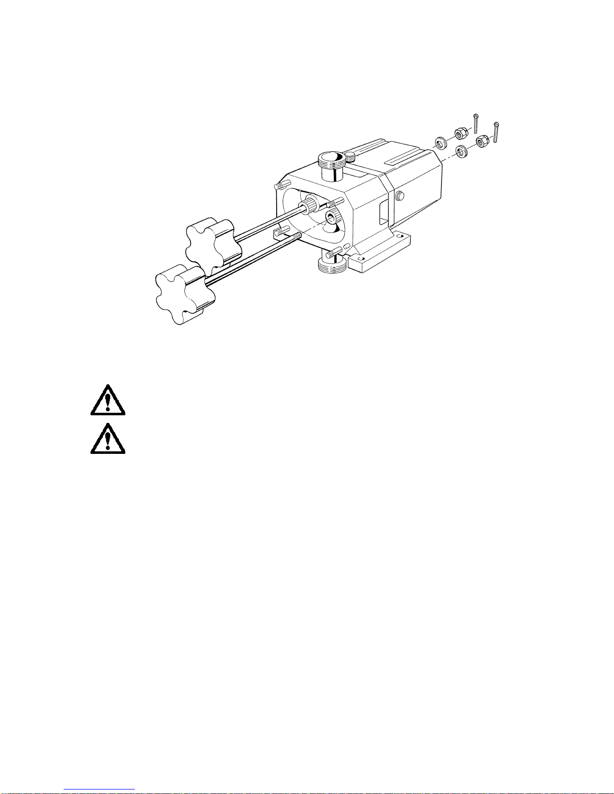
Fig 15
Removal of the rotors will necessitate gaining access to the end of both the drive and
lay shafts by removal of the coupling guard and drive coupling assembly. It will depend
upon the specific arrangement of components that have been used as to whether or
not the pump will need to be removed from its mounting to allow this.
- Follow recommended Shutdown Procedure refer to section 3.5.
- Gradually loosen front cover retaining dome nuts (36), care should be
taken as there may still be residual product and pressure in the pump
head and as the dome nuts are loosened this will vent to atmosphere.
- Remove dome nuts (36).
- Remove front cover (38), using lever slots where necessary, and the front
cover joint ring (39), taking care not to damage the sealing grooves in the
rotorcase (40) and front cover (38). Note that front cover (38) is located
by dowels (80).
- Remove split pins (82) from rotor (41) draw bolts, and discard, as they
are not re-useable.
- Remove castellated nuts (81) from rotor (41) draw bolts. Hexagonal
sections are provided on the shafts (9 & 10) to allow use of an open
ended spanner to stop shafts (9 &10) turning.
- Remove disc springs (83) from rotor (41) draw bolts, noting orientation.
- Remove rotors (41) from shafts (9 and 10) by gently tapping on ends of
draw bolts with a soft-faced mallet, then pulling out. Note that each rotor
(41) has its own integral draw bolt permanently attached. Take care not
to damage the mechanical seal faces which are located in the back face
of each rotor (41).
Page 28
Page 28
4.1.2 Cartridge Removal
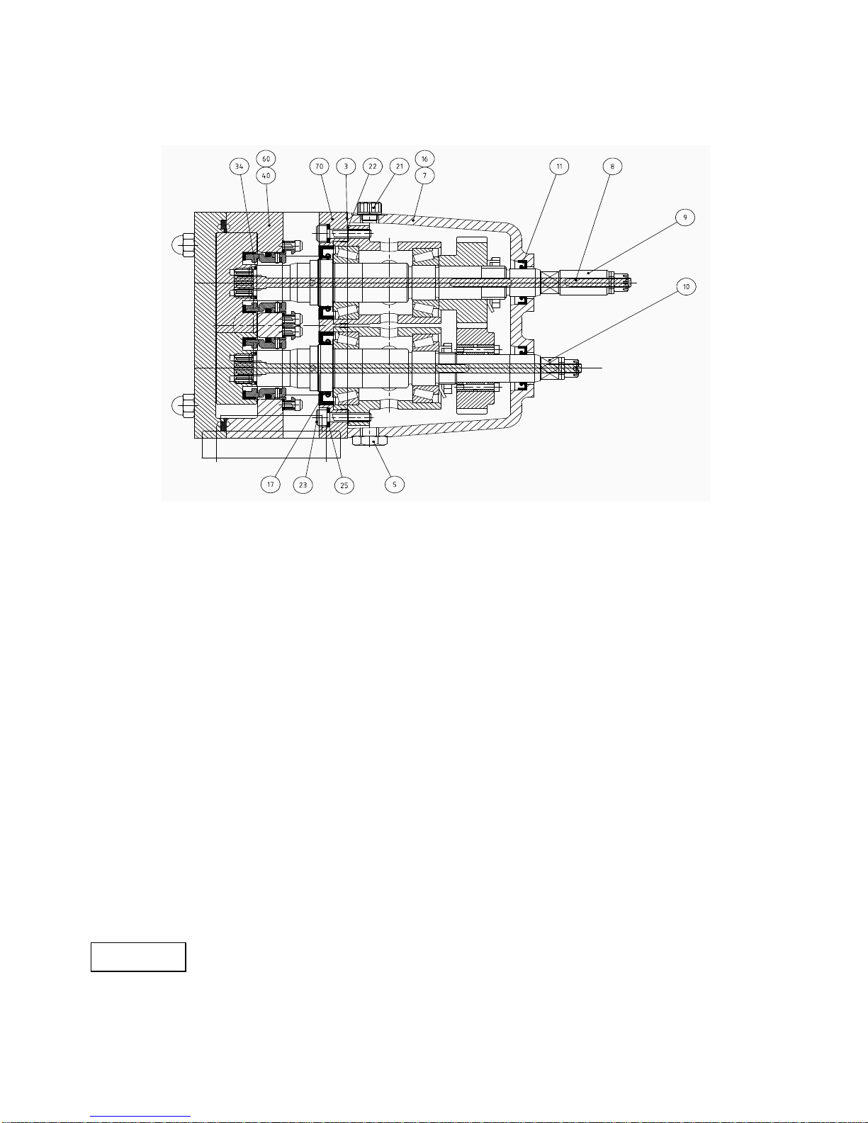
(after completing 4.1.1) - see Fig 16
Before proceeding with cartridge removal, remove mechanical seals, see section 4.5.
- Remove o-rings (34) from shafts (9 &10) and discard, do not re-use.
- Remove drive coupling from drive shaft (9), if not already removed.
- Remove drive key (8).
- Remove gearbox assembly retaining screws (7).
- Remove gearbox assembly from rotorcase (40), using levers in slots if
necessary. Note that mounting plate (70) is located onto by dowel (60).
- Remove oil drain plug (5) and breather (21), drain oil into suitable
container and retain if later inspection is required.
- Remove gearbox cover retaining screw (74) and sealing washer (25).
- Remove gearbox cover (16) and gasket (3) from mounting plate (70).
- Remove lipseals (11) from gearbox cover (16).
- Remove cartridge assembly retaining screw (23) & sealing washer (25).
- Extract shaft cartridge assemblies from mounting plate (70) take care not
to damage the shim (22). Keep shims in sets and identify position.
Note: Shims (22) may be different for each cartridge and therefore must
be kept with their respective cartridge.
- Remove front oil seals (17) from mounting plate (70).
WWAARRNNIINNGG
Page 29
Page 29
4.1.3 Cartridge Dismantling
4.1.3.1 Drive Shaft Cartridge Dismantling
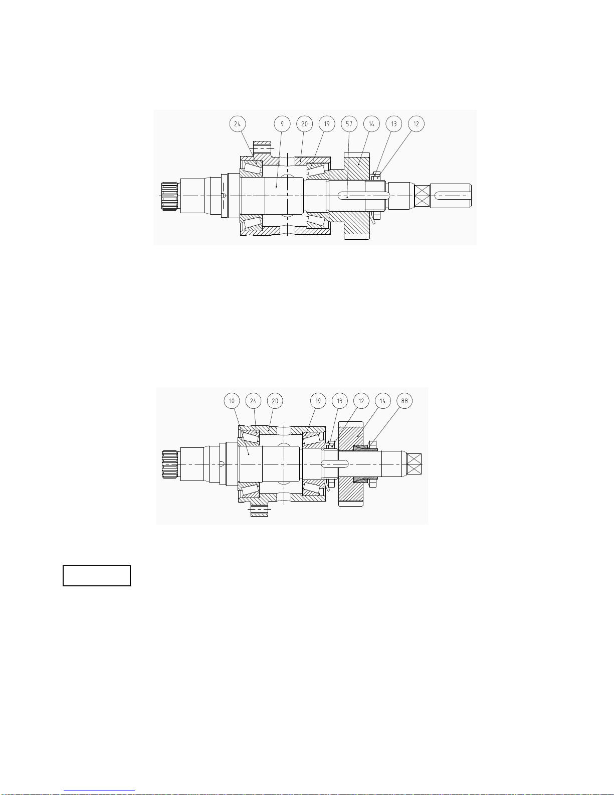
Fig 17
- Remove locknut (12) and tab washer (13).
- Remove timing gear (14) and gear key (57).
- Remove drive shaft (9) from bearing sleeve (20).
- Remove bearing (24) inner cone from drive shaft (9).
- Remove bearing (19 & 24) cups from bearing sleeve (20).
4.1.3.2 Lay shaft Cartridge Dismantling
Fig 18
- Release the clamping screws of the torque lock assembly (88)
gradually in a diagonal sequence until free.
Never completely undo one screw after another as this would cause the
last screw to be subjected to the total spring back force exerted by the
torque lock assembly (88) causing it to block.
- Remove timing gear (14) and torque lock assembly (88).
- Remove locknut (12) and tab washer (13).
- Remove lay shaft (10) from bearing sleeve (20).
- Remove bearing (24) inner cone from lay shaft (10).
- Remove bearing (19 & 24) cups from bearing sleeve (20).
WWAARRNNIINNGG
Page 30
Page 30
4.2 SQ1 Series Pumps - Assembly
4.2.1 Cartridge Assembly
4.2.1.1 Drive Shaft Cartridge Assembly
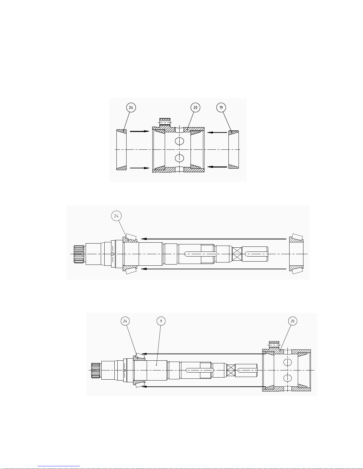
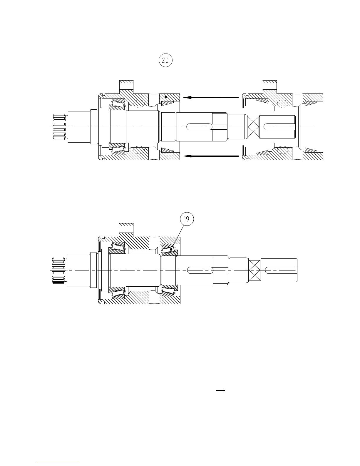
- Install bearing (19 & 24) cups to bearing sleeve (20), see Fig 19.
Fig 19
- Install front bearing (24) cone onto drive shaft (9) see Fig 20.
Fig 20
- Install bearing sleeve (20) to drive shaft (9) with securing lugs towards
the spline end of the shaft so that the bearing (24) cup locates with the
cone see Fig 21.
Fig 21
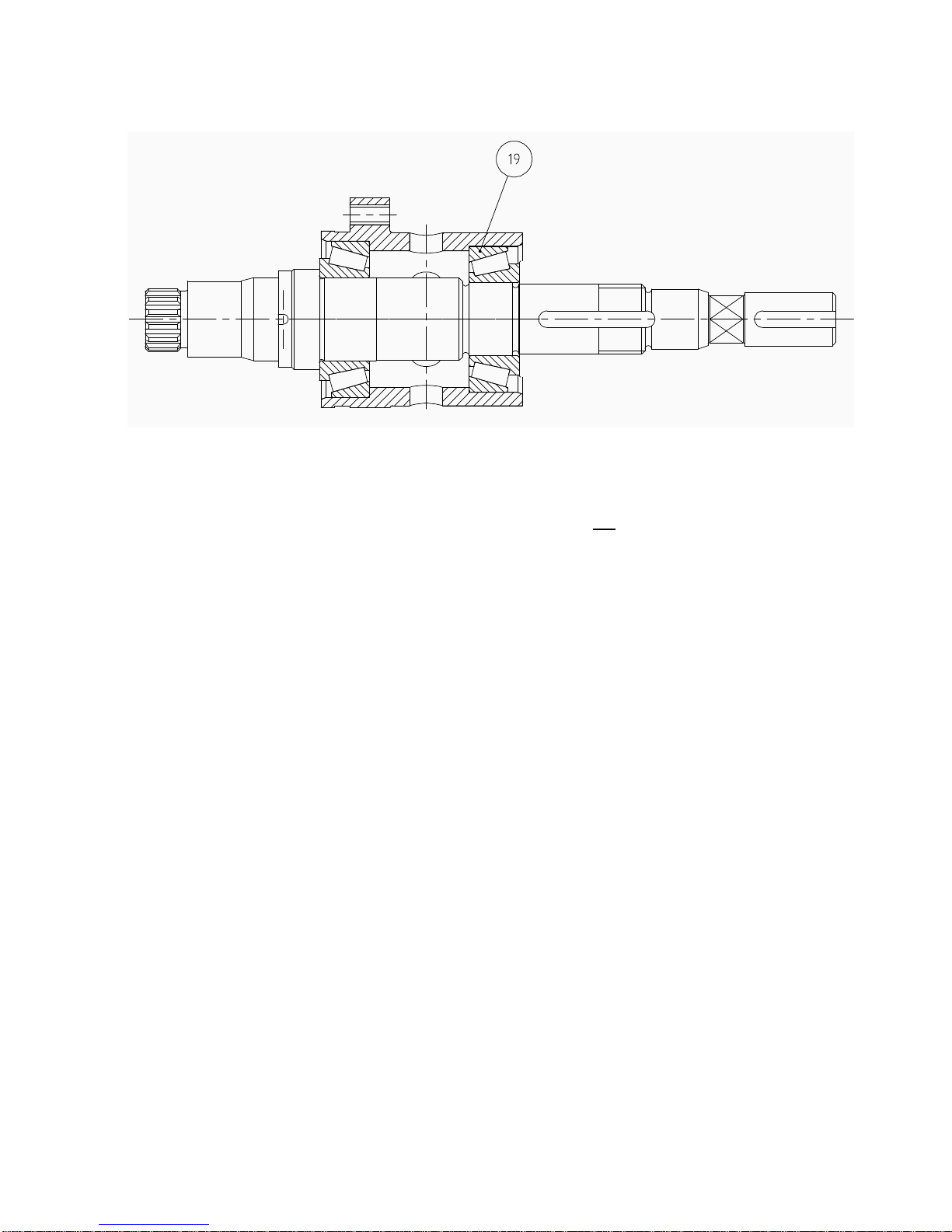
- Install rear bearing cone (19) to drive shaft (9) see Fig 22. Do not use
excessive pressure as rolling torque is achieved by adjusting rear lock
nut (12).
Page 31
Page 31
Fig 22
- Install gear key (57) and gear (14) into position ensuring gear boss
abuts with rear bearing (19) cone.
- Install tab washer (13) and lock nut (12). Do not secure tab washer
(13).
- Install rotor (41) to the cartridge assembly, securing with castellated nut
(81) (it’s not necessary to install springs (83) or pin (82) for this
operation).
- Carefully mount the cartridge/rotor assembly into a vice horizontally,
gripping on the bearing sleeve (20). Do not over tighten the vice, the
bearing sleeve (20) is a precision component and should not be
distorted.
- Tighten lock nut (12) and adjust to achieve correct rolling torque, refer
to section 5.2. Measure the rolling torque using a torque meter, which
can conveniently drive onto the castellated nut (81) by use of a socket.
If the rolling torque does not correspond to the required setting, for
rolling torque settings refer to section 5.2, adjust the lock nut (12).
Secure tab washer (13).
- Remove castellated nut (81) and rotor (41).
Page 32
Page 32
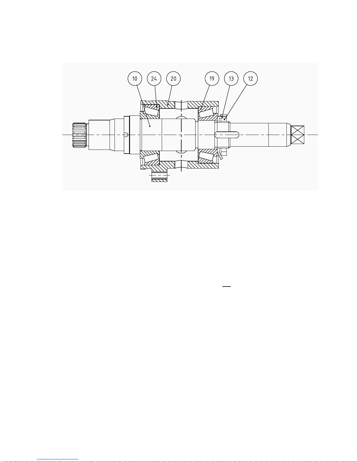
4.2.1.2 Lay shaft Cartridge Assembly
Fig 23
- Install bearing (19 & 24) cups to bearing sleeve (20), as in Fig 19.
- Install front bearing cone (24) onto lay shaft (10), as in Fig 20.
- Install bearing sleeve (20) to lay shaft (10) with securing lugs towards
the spline end of the shaft so that the bearing (24) cup locates with the
cone, as in Fig 21.
- Install rear bearing (19) cone to lay shaft (10), as in Fig 22. Do not use
excessive pressure as rolling torque is achieved by adjusting rear lock
nut (12).
- Install tab washer (13) and lock nut (12). Do not secure tab washer
(13).
- Install rotor (41) to the cartridge assembly, securing with castellated nut
(81) (it is not necessary to install disc springs (83) or split-pin (82) for
this operation).
- Carefully mount the cartridge/rotor assembly into a vice in horizontal
plane, gripping on the bearing sleeve (20). Do not over tighten the vice
as the bearing sleeve (20) is a precision component and should not be
distorted.
- Tighten lock nut (12) and adjust to achieve correct rolling torque, refer
to section 5.2. Measure the rolling torque using a torque meter, which
can conveniently drive onto the castellated nut (81) by use of a socket.
If the rolling torque does not correspond to the required setting, for
rolling torque settings refer to section 5.2, adjust the lock nut (12).
Secure tab washer (13).
- Remove castellated nut (81) and rotor (41).
Page 33
Page 33
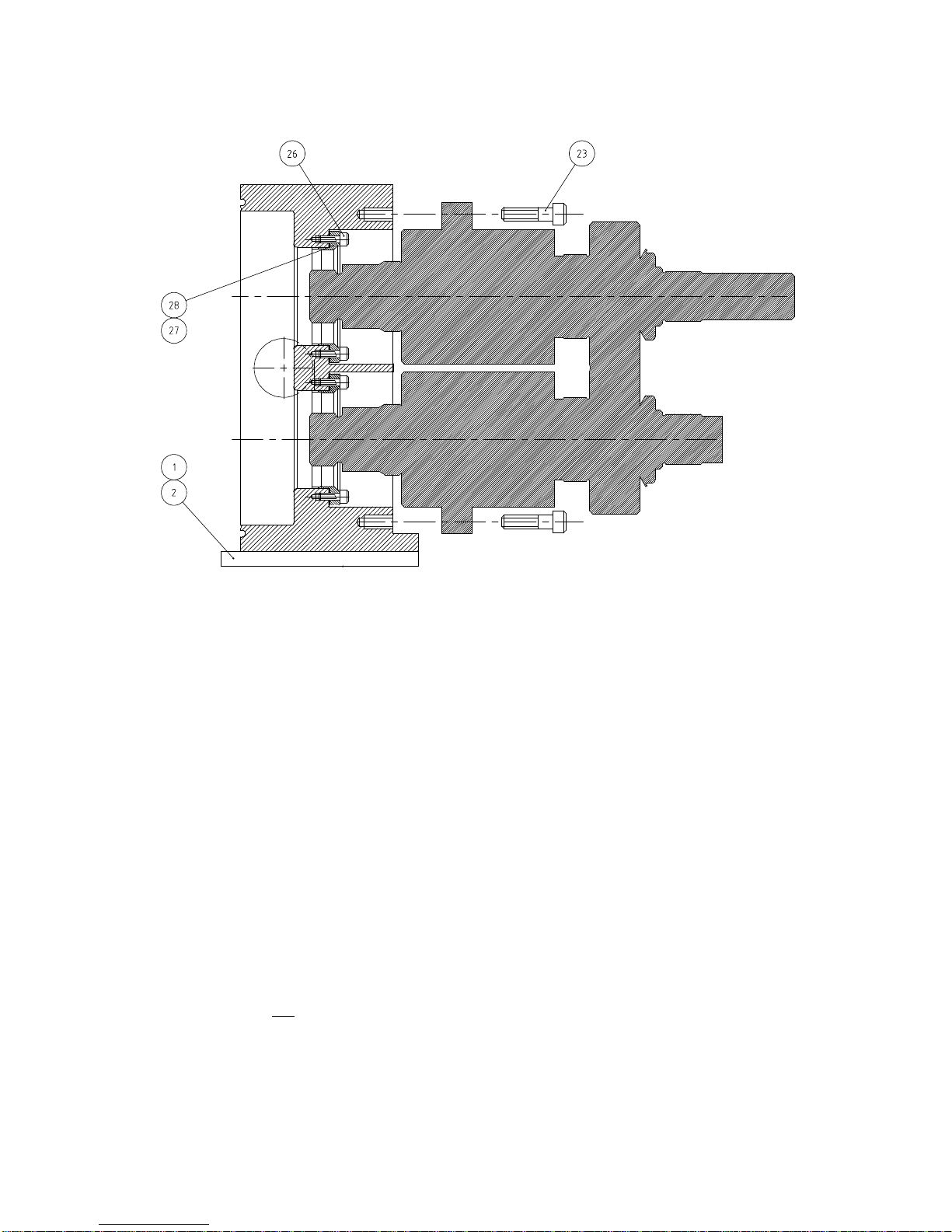
4.2.2 Cartridge/Mounting Plate/Rotorcase Assembly
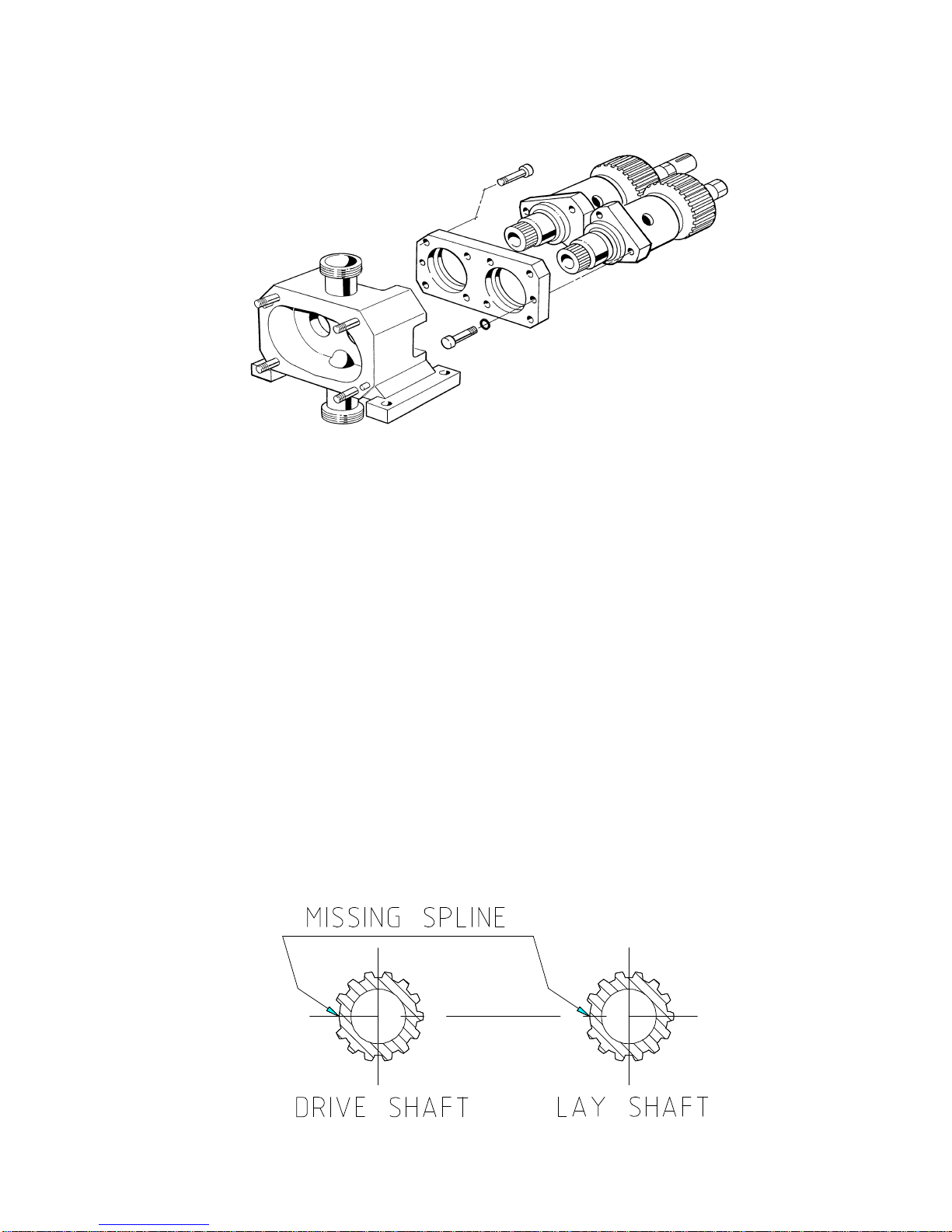
Fig 24
- If not already installed, install feet (1) to rotorcase (40) using cap head
screws (2).
Note: If necessary for the hygienic requirements of the installation, the feet (1)
should be sealed to the rotorcase (40) with a suitable sealing agent.
- If not already installed, install the mechanical seal housing (28) with
gasket (27) to the rear of the rotorcase (40) and secure with screw (26).
- Assemble cartridges into mounting plate (70) rear bores securing with
cap head screws (23) (tightening to correct torque, refer to section 5.2)
and sealing washers (25), which are located under heads of screws
(23). Do not install shims (22) at this stage.
- Ensure mating faces are totally clean, then install mounting plate (70) to
rotorcase (40), (noting that it locates onto dowels (60)), securing with
cap head screws (74) (which are actually the screws used to finally
install gearbox cover (16)).
- Rotate shafts (9 & 10) so as to position the gaps made by the missing
splines in positions shown in Fig 25.
Fig 25
Page 34
Page 34
- Install rotors (41), securing with castellated nuts (81), tightening to
correct torque refer to section 5.2. Hexagonal sections are provided on
the shafts (9 & 10) to allow use of an open ended wrench in association
with a torque wrench on the castellated nut (81). (It is not necessary to
install disc springs (83) or split-pins (82) for this operation).
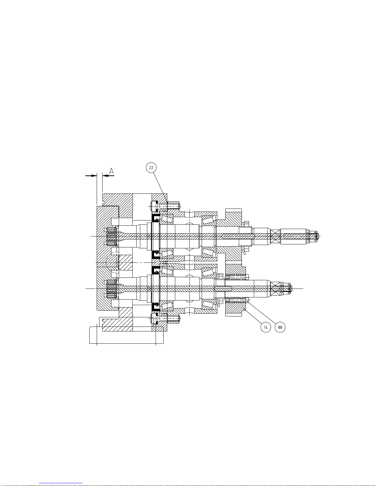
- Taking care not to cause any scratching or other damage of
components, use a depth micrometer or similar device measure
"actual" rotor front protrusion, this is the protrusion of the rotor in front of
the front face of the rotorcase. Select "required" front protrusion (A)
from the Clearance Chart, refer to section 5.1, see Fig 26. The
difference between the "actual" measured protrusion and the "required"
protrusion, as given on the Clearance Chart, is the amount of shim (22)
that needs to be added.
Fig 26
- Having determined the amount of shim (22) to be added, remove
castellated nuts (81) and rotors (41). Remove cap head screws (74)
and mounting plate (70) from rotorcase (40). Remove cap head screws
(23) and cartridge assemblies from mounting plate (70). Add
appropriate amount of shim between mounting plate (70) and nose of
bearing sleeves (20).
- Install lipseals (17) to mounting plate (70).
- Re-assemble cartridge assemblies, rotorcase (40) and mounting plate
(70), (ensuring mating faces are totally clean). With shafts positioned as
Fig 25, re-install rotors (41) and re-check rotor front protrusion
dimensions.
Page 35
Page 35
- Install torque lock assembly (88) to lay shaft (10).
- Install timing gear (14) to torque lock assembly (88) such that the timing
gears (14) are fully engaged and aligned. The mating face of torque
lock assembly (88) should not protrude on either side of the lay timing
gear (14).
- Tighten the clamping screws of the torque lock assembly (88) evenly in
diagonal order until all play is eliminated.
- Tighten the clamping screws slightly further such that the timing gear
(14) is just retained on lay shaft (10).
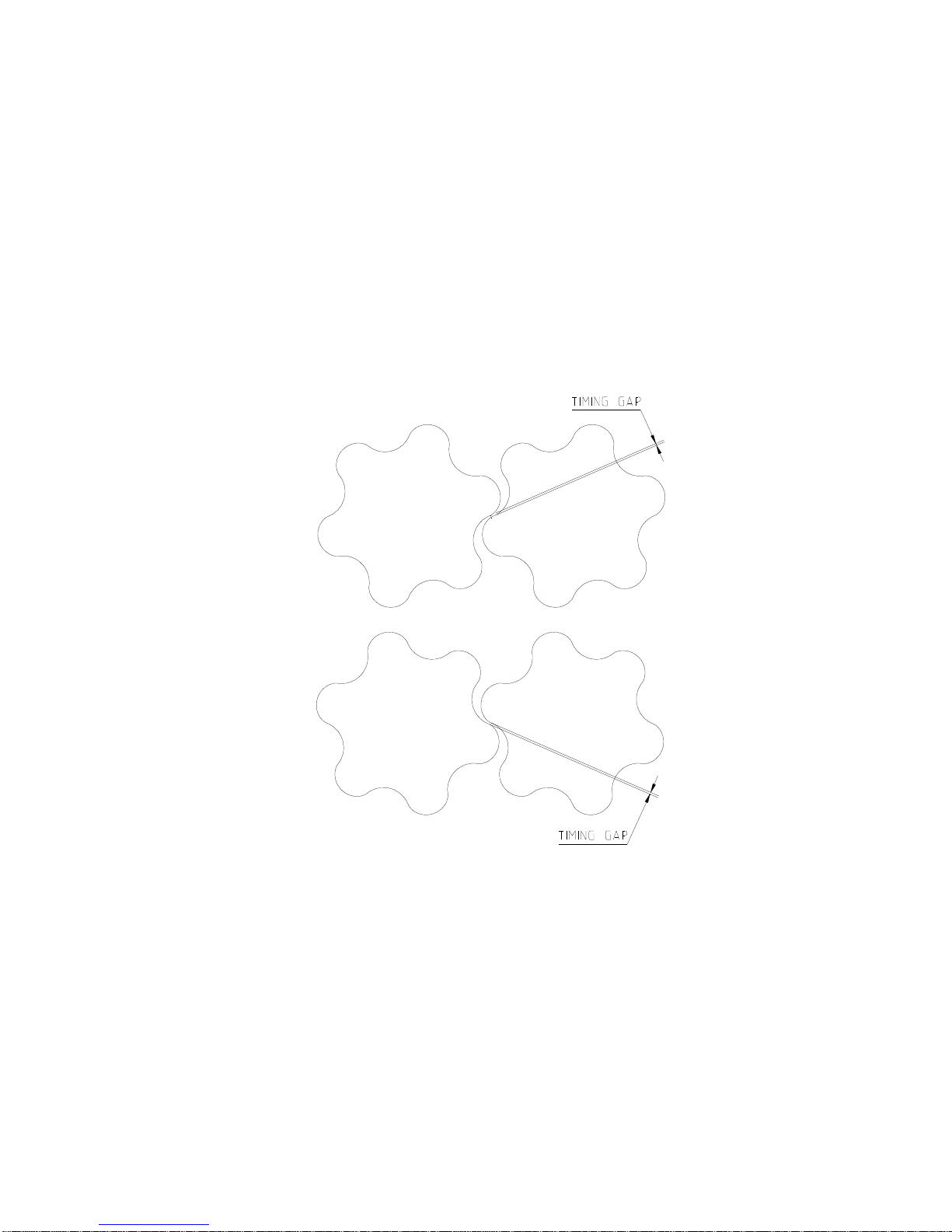
4.2.3 Setting Rotor Timing
Fig 27
- The timing clearances for the rotors must be equalised and can be
adjusted by turning shafts (9 & 10) in relation to each other. Once
timing clearances have been optimised, the clamping screws of torque
lock assembly (88) can be tightened gradually in diagonal sequence to
correct torque, refer to section 5.2.
- After tightening of torque lock assembly (88) the timing clearances for
the rotors should be re-checked.
- Once timing clearances have been optimised; remove castellated nuts
(81) and rotors (41).
- Remove screws (74) and mounting plate (70) from rotorcase (40).
Page 36
Page 36
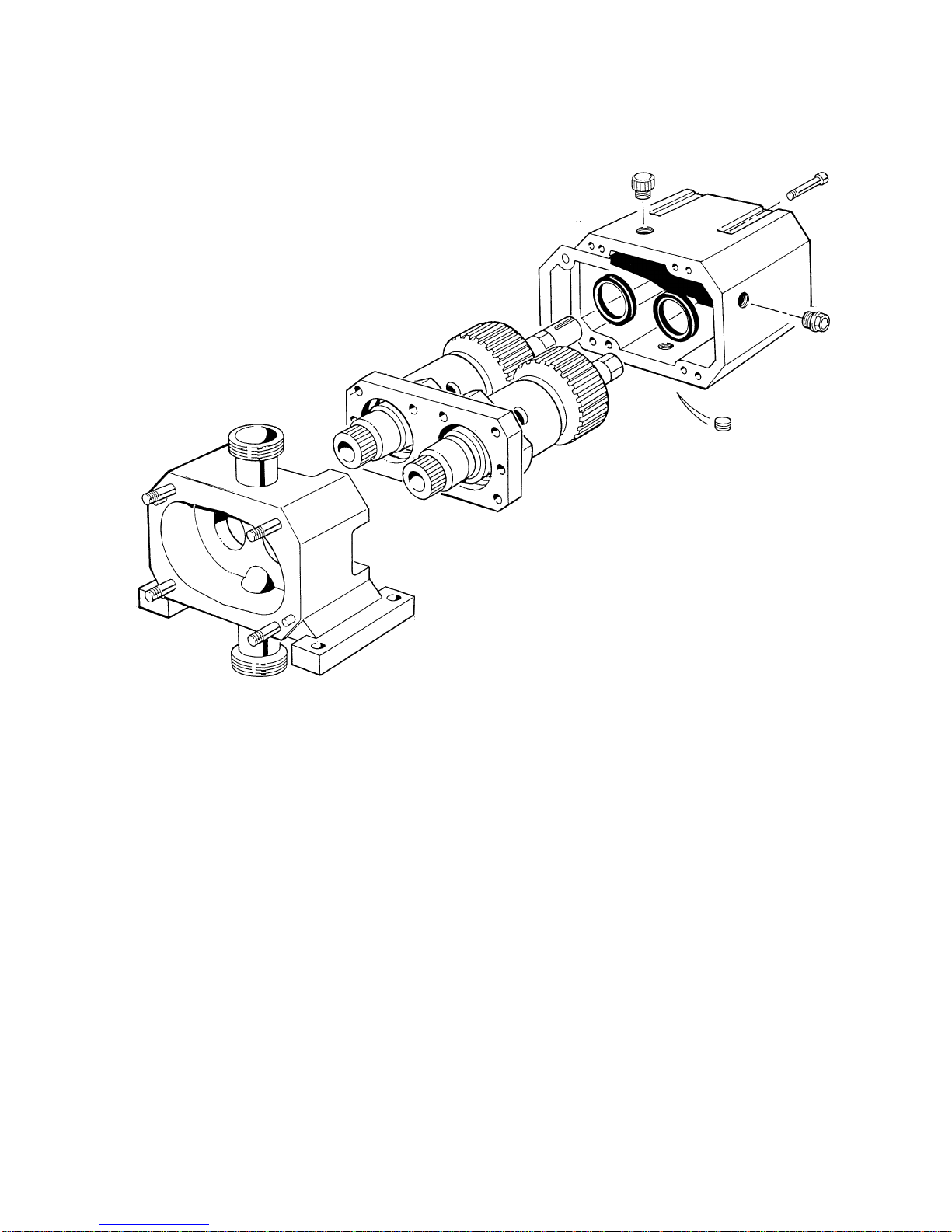
4.2.4 Gearbox Assembly
Fig 28
- Install lipseals (11) to gearbox cover (16).
- Install breather (21); drain plugs (5) and sight glass (6) in required
position in gearbox cover (16).
Note: The sight glass (6) must be installed in the upper tapped hole in the side
of the gearbox cover (16). Remember to fill the gearbox with oil prior to
start up. For recommended lubricant capacities and grades refer to
section 5.3.
- Install gearbox cover (16) with gasket (3) to mounting plate (70)
securing with screws (74) (tightening to correct torque, refer to section
5.2) and sealing washers (25), which are located under heads of
screws (74).
- Install gearbox cover (16) / mounting plate (70) assembly to rotorcase
(40) (noting that it locates onto dowels (60)), securing with screws (7),
tightening to correct torque, refer to section 5.2.
Page 37
Page 37
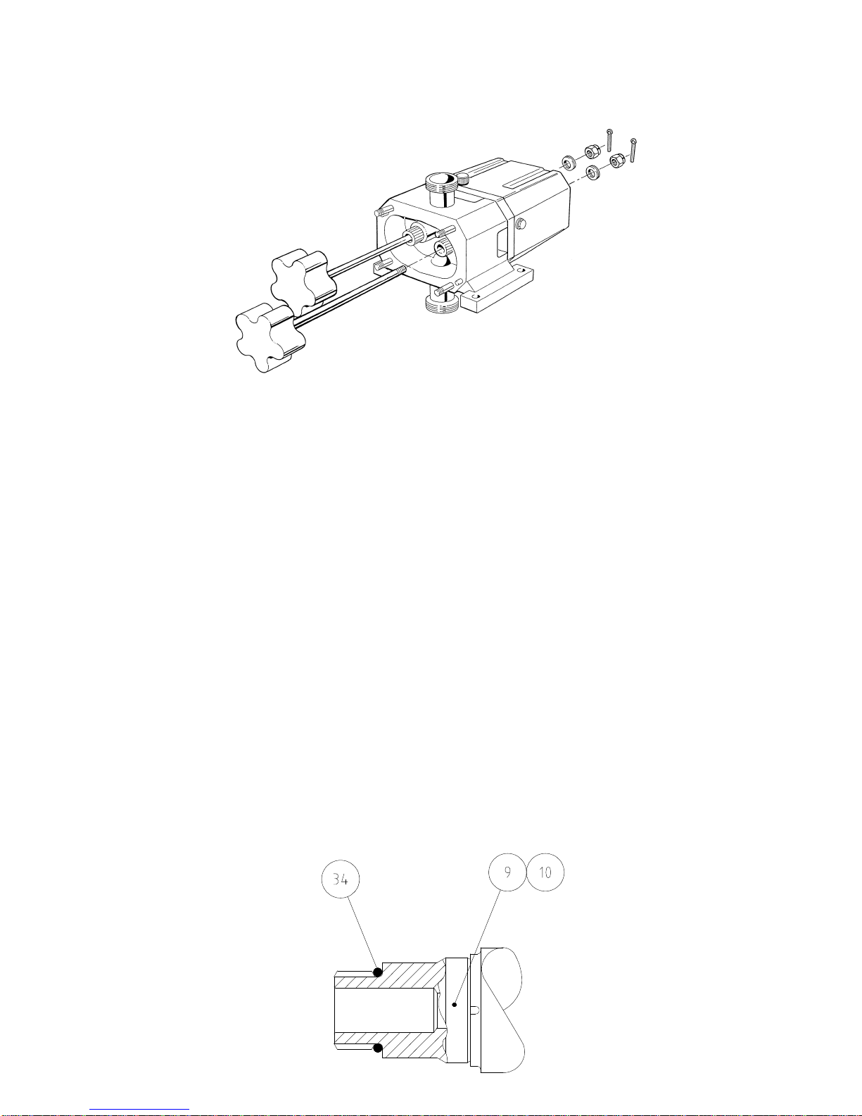
4.2.5 Rotor Assembly and Checking Clearances
Fig 29
- Do not install mechanical seals at this point.
- Install rotors (41) to shafts (9 and 10) in rotorcase (40).
- Install castellated nuts (81) to rotor (41) draw bolts, tightening to correct
torque, refer to section 5.2. Hexagonal sections are provided on the
shafts (9 & 10) to allow use of an open ended spanner in association
with a torque wrench acting on the castellated nut (81).
- Using a depth micrometer or similar device measure "actual" rotor front
protrusion (A), this is the protrusion of the rotor in front of the front face
of the rotorcase and check that this corresponds to the appropriate
protrusion as indicated on the Clearance Chart, refer to section 5.1.
- If the front protrusion (A) is incorrect, adjustment of the shims (22)
between the mounting plate and cartridge is required, refer to section
4.2.2 Cartridge / Mounting Plate / Rotorcase Assembly.
- With rotors (41) installed, check all clearances, front (A), radial (C), rear
(B) and mesh (D), against the Clearance Chart refer to section 5.1.
- Remove castellated nuts (81) and rotors (41).
- Install mechanical seals; refer to section 4.5 Mechanical Seal
Installation and Removal.
- Install new o-rings (34) to shafts (9 & 10) see Fig 30.
Fig 30
Page 38
Page 38
- Install rotors (41) to shafts (9 and 10) in rotorcase (40).
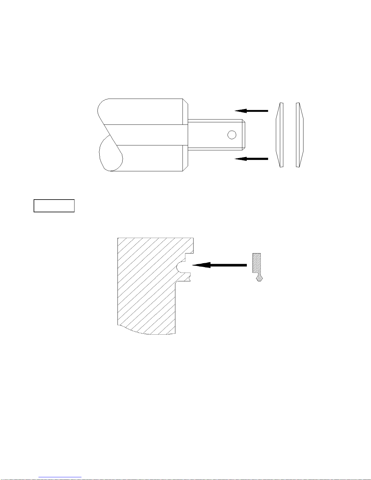
- Install disc springs (83) (ensuring correct orientation, see Fig 31) and
castellated nuts (81) to rotor (41) draw bolts, tightening to correct
torque, refer to section 5.2.
Fig 31
- Install joint ring (39) to front cover (38).
Note: Joint Ring (39) must be installed the right way round, see Fig 32.
The Joint Ring (39) "clips" into place on the register. Make sure that the
Joint Ring (39) is correctly located around its entire circumference before
proceeding.
Fig 32
- Install front cover (38) to rotorcase (40) (noting that it locates onto
dowels (80)), securing with dome nuts (36), tightening to correct torque,
refer to section 5.2. Make certain that the joint ring (39) is not dislodged
from its correct position during the installing operation.
- Install new split pins (82) through castellations of castle nuts (81) and
drilled holes in rotor (41) draw bolts. It may be found necessary to
loosen castellated nut (81) fractionally to align holes. Bend ends of
split-pins (82) over to secure, ensuring that ends will not interfere with
drive coupling hub when it is reinstalled to drive shaft (9).
WWAARRNNIINNGG
Page 39
Page 39
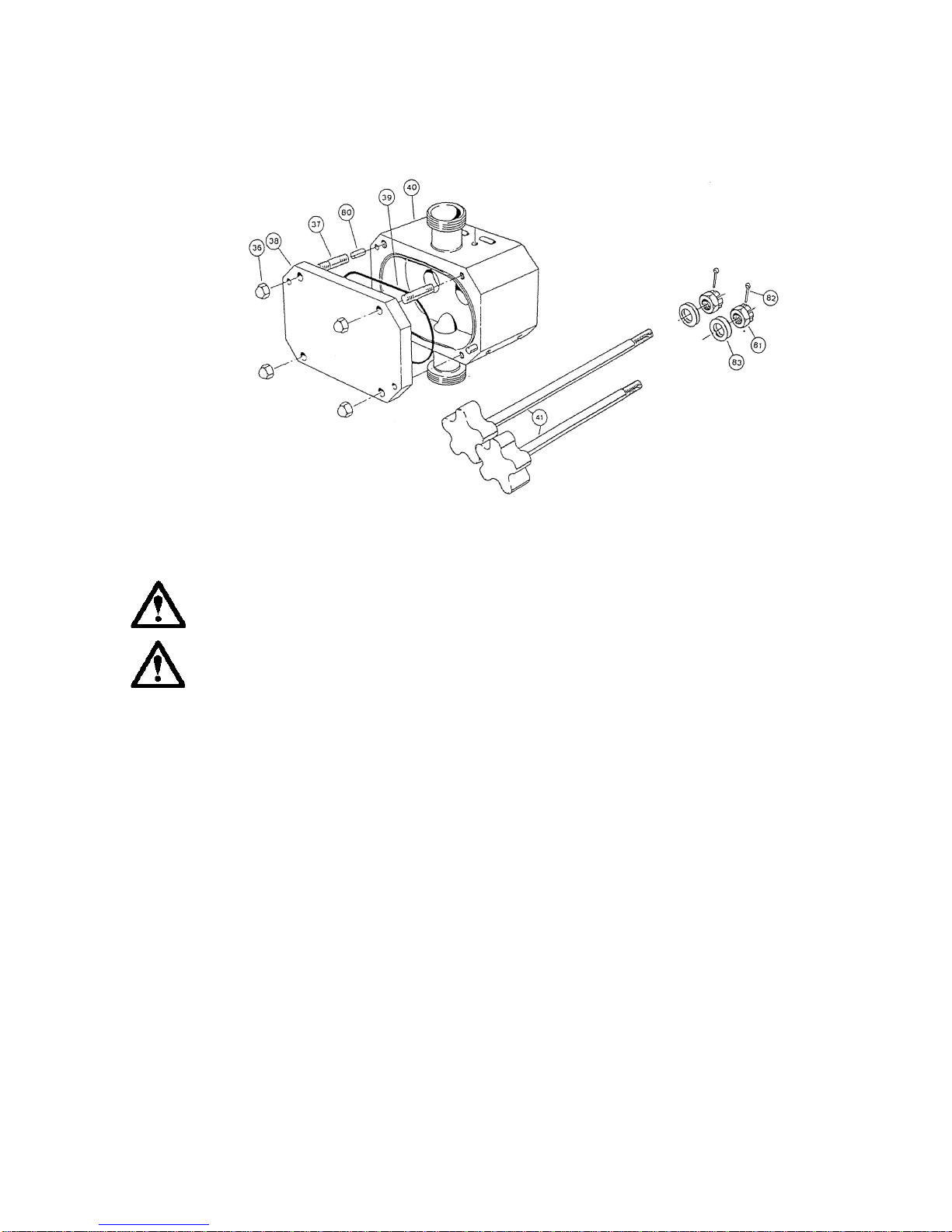
4.3 SQ 2, 3, 4 - Dismantling
4.3.1 Front Cover and Rotor Removal
Fig 33
Removal of the rotors will necessitate gaining access to the end of both the drive and
lay shafts by removal of the coupling guard and drive coupling assembly. It will depend
upon the specific arrangement of components that have been used as to whether or
not the pump will need to be removed from its mounting to allow this.
- Follow recommended Shutdown Procedure - refer to section 3.5.
- Gradually loosen front cover retaining dome nuts (36), care should be
taken as there may still be residual product and pressure in the pump
head and as the dome nuts are loosened this will vent to atmosphere.
- Remove dome nuts (36).
- Remove front cover (38), using lever slots where necessary, and the
front cover joint ring (39), taking care not to damage the sealing
grooves in the rotorcase (40) and front cover (38). Note that front cover
(38) is located by dowels (80).
- Remove split pins (82) from rotor (41) draw bolts, and discard, as they
are not re-useable.
- Remove castellated nuts (81) from rotor (41) draw bolts. Hexagonal
sections are provided on the shafts (9 & 10) to allow use of an open
ended spanner to stop shafts (9 &10) turning.
- Remove disc springs (83) from shafts, noting their orientation
- Remove rotors (41) from shafts (9 and 10) by gently tapping on ends of
draw bolts with a soft-faced mallet, then pulling out. Note that each
rotor (41) has its own integral draw bolt permanently attached. Take
care not to damage the mechanical seal faces which are located in the
back face of each rotor (41).
Page 40

Page 40
4.3.2 Cartridge Removal (after completing 4.3.1)
Fig 34
The following procedures assume the pump has been removed from the baseplate.
Before proceeding with cartridge removal remove mechanical seals see section 4.5.
- Remove o-rings (34) from shafts (9 &10) and discard they are not re-useable.
- Remove oil drain plug (5) and breather (21), drain oil into suitable container
and retain if later inspection is required.
- Remove drive coupling, if not already removed.
- Remove drive key (8).
- Remove gearbox cover retaining screws (7).
- Remove gearbox cover (16) and gasket (3).
- Remove lipseals (11) from gearbox cover (16).
- Remove shaft cartridge retaining screws (23).
- Extract shaft cartridge assy using lever slots if necessary taking care not to
damage shims (22). Keep shims (22) in sets and identify position.
Note: Shims (22) may be different for each cartridge and therefore must be
kept with their respective cartridge.
WWAARRNNIINNGG
Page 41
Page 41
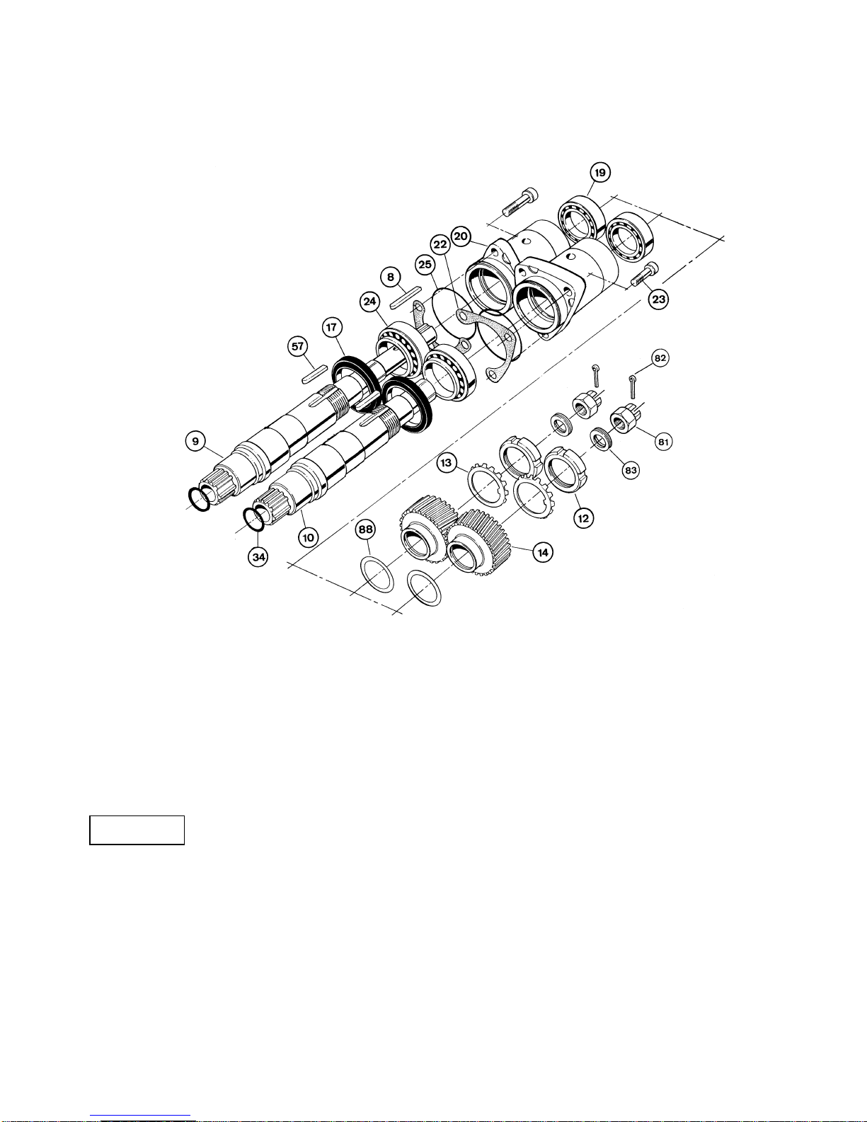
4.3.3 Cartridge Dismantling
Fig 35
- Remove o rings (25) from bearing sleeves (20)
- Remove locknut (12) and tab washer (13).
- Remove timing gear (14) noting that the drive shaft gear (stamped D)
has a right hand helix and the lay shaft gear (stamped L) a left hand
helix.
- Remove shims (88) from shafts (9 & 10). Keep in sets and identify
positions.
Note: Shims (88) may be different for each cartridge and therefore must
be kept with their respective cartridge.
- Remove gear key (57).
- Remove front oil seal (17).
- Remove shaft (9 or 10) from bearing sleeve (20).
- Remove bearing (24) inner cones from shafts (9 and 10).
- Remove bearing (24) cups from bearing sleeves (20).
WWAARRNNIINNGG
Page 42
Page 42
4.4 SQ 2, 3, 4 - Assembly
4.4.1 Cartridge Assembly
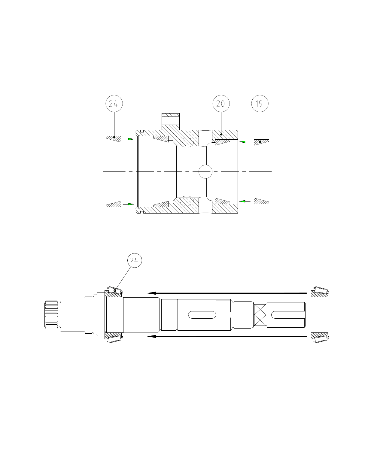
- Install bearing (19 & 24) cups to bearing sleeves (20), see Fig 36.
Fig 36
- Install front bearing (24) cones onto shafts (9 and 10) see Fig 37.
Fig 37
- Install bearing sleeves (20) to shafts (9 and 10) with securing lugs
towards the spline end of the shaft so that the bearing (24) cup locates
with the cone (24) see Fig 38.
Page 43
Page 43
Fig 38
- Install rear bearing (19) cones to shafts (9 and 10) see Fig 39. Do not
use excessive pressure as rolling torque is achieved by adjusting rear
lock nuts (12).
Fig 39
- Install gear keys (57) and gears (14) into position ensuring gear boss
abuts with rear bearing (19) cone.
Note: Right hand helix for drive shaft gear (stamped D), left hand helix for
lay shaft gear (stamped L).
Note: When ordering spare timing gears it is essential to purchase and
install these as a pair.
- Install tab washers (13) and nuts (12). Do not secure tab washers (13).
Page 44
Page 44
4.4.2 Cartridge to Rotorcase Assembly
- If not installed, secure feet (1) to rotorcase (40) using cap screws (2).
Note: If necessary for the hygienic requirements of the installation, the feet (1)
should be sealed to the rotorcase (40) with a suitable sealing agent.
- If not already installed, install the mechanical seal housing (28) with
gasket (27) on SQ2 models or o-ring (27) on SQ3 & SQ4 models to the
rear of the rotorcase (40) and secure with screws (26).
- Install rotors (41) to the individual cartridge assemblies, securing with
castellated nuts (81) (it is not necessary to install disc springs (83) or
split-pins (82) for this operation).
- Carefully mount one of the cartridge/rotor assemblies into a vice in
horizontal plane, gripping on the bearing sleeve (20). Do not over
tighten the vice as the bearing sleeve (20) is a precision component
and should not be distorted.
- Tighten lock nut (12) and adjust to achieve correct rolling torque, refer
to section 5.2. Measure the rolling torque using a torque meter, which
can conveniently drive onto the castellated nut (81) by use of a socket.
If the rolling torque does not correspond to the required setting, for
rolling torque settings refer to section 5.2, adjust the lock nut (12). Do
not secure tab washers (13).
- Remove castellated nuts (81) and rotors (41).
- It is not necessary to install o-rings (25) to front diameter of bearing
sleeves (20) at this stage.
Fig 40
Page 45
Page 45
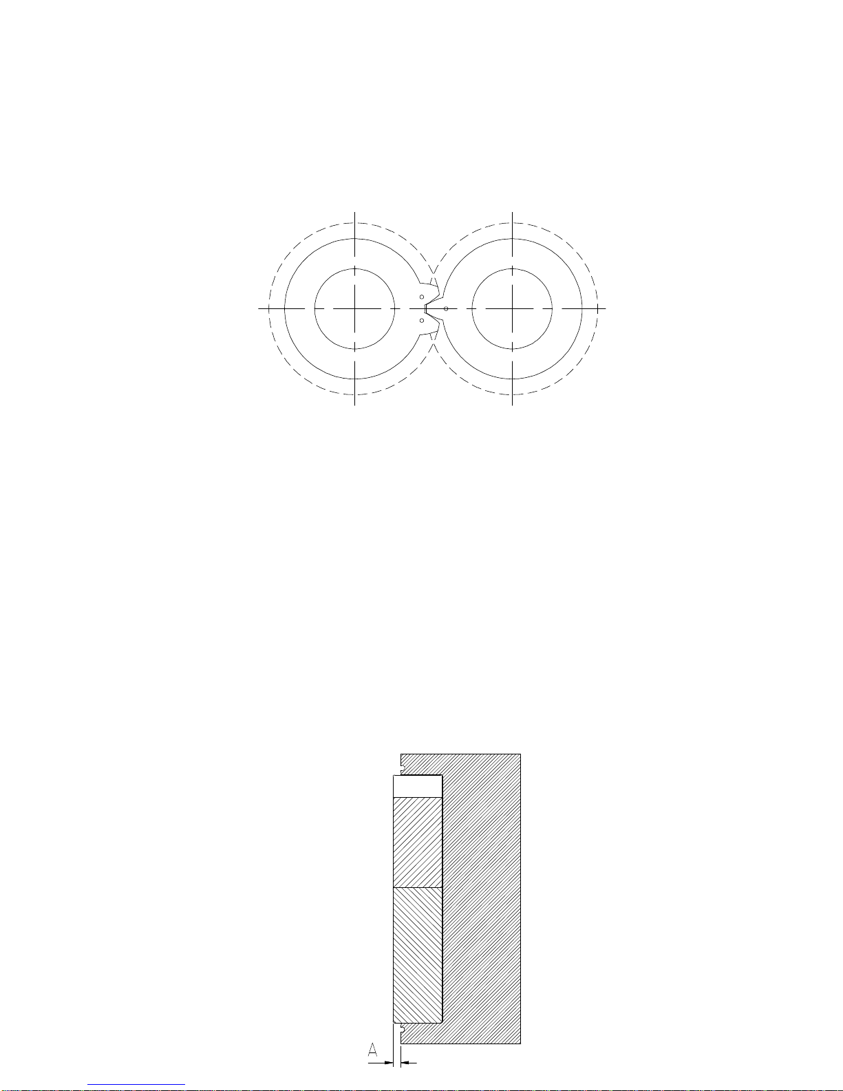
- Assemble cartridges into rotorcase (40) rear bores ensuring that timing
marks on the timing gears (14) are in mesh (single dot on drive shaft
gear, two dots on lay shaft gear). The timing gears are in correct mesh
when the single dot on the drive shaft gear is between the two dots on
the lay shaft gear, see Fig 41.
Fig 41
- Secure cartridges to rotorcase (40) with cap head screws (23),
tightening to correct torque, refer to section 5.2. No shims (22) should
be installed at this stage.
- Install rotors (41), securing with castellated nuts (81), tightening to
correct torque, refer to section 5.2. Hexagonal sections are provided on
the shafts (9 & 10) to allow use of an open ended spanner in
association with a torque wrench acting on the castellated nut (81). (It is
not necessary to install disc springs (83) or split-pins (82) for this
operation).
- Taking care not to cause any scratching or other damage of
components, use a depth micrometer or similar device measure
"actual" rotor front protrusion, (A), this is the protrusion of the rotor in
front of the front face of the rotorcase. Select "required" front protrusion
(A) from the Clearance Chart, refer to section 5.1, see Fig 42. The
difference between the "actual" measured protrusion and the "required"
protrusion, as given on the Clearance Chart, is the amount of shim (22)
that needs to be added.
Fig 42
Page 46
Page 46
- Having determined the amount of shim (22) to be added, remove
castellated nuts (81) and rotors (41). Remove cap head screws (23).
Ease cartridge from rotorcase (40) using lever slots to create a gap to
allow installation of shims (22). Add appropriate amount of shim
between rotorcase (40) and shaft cartridge flange. Shims are either
marked with their thickness or are colour coded as follows:
Blue = 0.050 mm (0.002”) thick
Green = 0.075 mm (0.003”) thick
Clear = 0.150 mm (0.006”) thick
White = 0.250 mm (0.010”) thick
- Secure cartridges to rotorcase (40) with cap head screws (23)
tightening to correct torque refer to section 5.2.
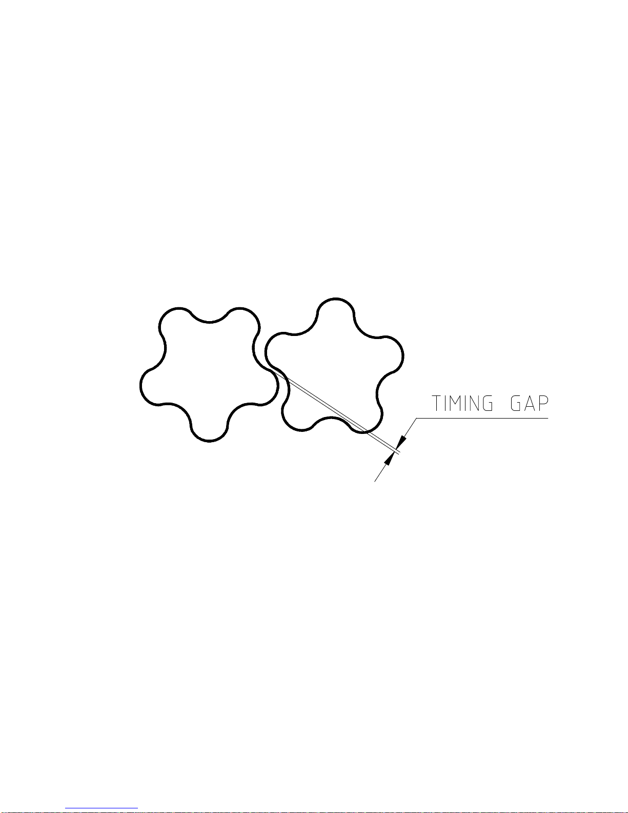
4.4.3 Setting Rotor Timing
Fig 43
- Install rotors (41) to cartridge assemblies, secure with castellated nuts
(81) (not necessary to install springs (83) or split-pins (82) for this
operation).
- If timing clearance, see fig 43, is larger on the upper side compared
with the lower side (when viewed on rotor fronts), shim (86) must be
added between boss of timing gear (14) and inner cone of bearing (19)
of the lay shaft (10). (As a guide to the thickness of shim required, to
change timing gap by 1 unit (say 0.1mm) shims of 3 units thickness
(say 0.3 mm) would be required.) Installation of shims (86) will
necessitate removal of castellated nuts (12), rotors (41), lock nuts (12),
tab washers (13) and timing gears (14). Having installed the correct
amount of shim (86), re-assemble timing gears (14), tab washers (13),
lock nuts (12), rotors (41) and castellated nuts (12).
- Once timing clearances have been confirmed as being equalised,
remove castellated nuts (81) and rotors (41).
- Remove cartridge assemblies from rotorcase (40) to allow final setting
of rolling torque refer to section 4.4.4. Keep shims (22) in sets and
identify position.
Page 47
Page 47
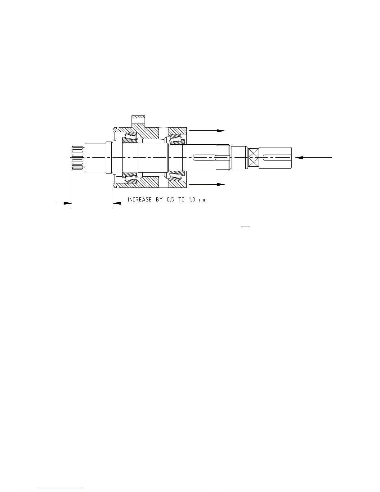
Fig 44
4.4.4 Final Setting of Cartridge Rolling Torque
- Remove lock nuts (12) and tab washers’ (13) from cartridge
assemblies.
- To ensure that the correct final rolling torque is applied, it is necessary
to remove any existing pre-load on bearings (19 & 24). This can be
achieved by pressing shaft (9 or 10) through the bearing sleeve (20) by
a distance of 0.5 to 1.0 mm, see Fig 44.
- Install tab washers (13) and lock nuts (12). Do not secure tab washers
(13).
- Install rotors (41) to the individual cartridge assemblies, securing with
castellated nuts (81) (it is not necessary to install disc springs (83) or
split-pins (82) for this operation).
- Carefully mount one of the cartridge/rotor assemblies into a vice in
horizontal plane, gripping on the bearing sleeve (20). Do not over
tighten the vice as the bearing sleeve (20) is a precision component
and should not be distorted.
- Tighten lock nut (12) and adjust to achieve correct rolling torque, refer
to section 5.2. Measure the rolling torque using a torque meter, which
can conveniently drive onto the castellated nut (81) by use of a socket.
If the rolling torque does not correspond to the required setting, for
rolling torque settings refer to section 5.2, adjust the lock nut (12).
- Secure tab washer (13) after setting correct rolling torque.
- Repeat rolling torque adjustment for other cartridge/rotor assembly.
- Remove castellated nuts (81) and rotors (41) from cartridge
assemblies. Install lipseals (17) to bearing sleeves (20) and install o
rings (25) to front outer diameter of bearing sleeves (20)
- Assemble cartridges into rotorcase (40) rear bores ensuring that timing
marks on the timing gears (14) are in mesh (single dot on drive shaft
gear, two dots on lay shaft gear). The timing gears are in correct mesh
when the single dot on the drive shaft gear is between the two dots on
the lay shaft gear.
Page 48
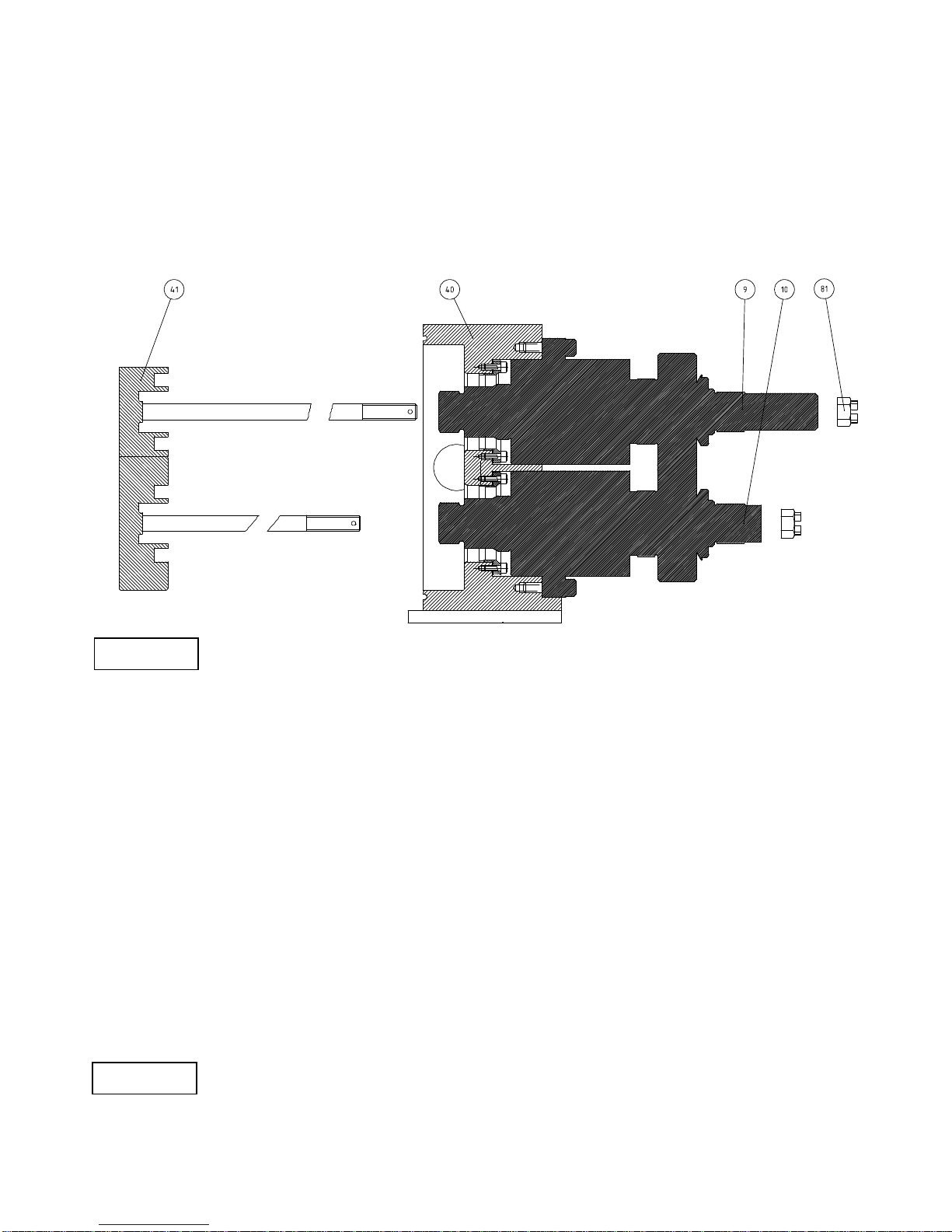
Page 48
- Install shim (22) sets, as determined in section 4.4.2, between
rotorcase (40) and shaft cartridge flange.
- Secure cartridges to rotorcase (40) with cap head screws (23),
tightening to correct torque refer to section 5.2.
4.4.5 Rotor Assembly and Setting Rotor Clearances
Fig 45
Note: Spare rotors are supplied in pairs & should be installed as such.
- Do not install mechanical seals at this point.
- Install rotors (41) to shafts (9 and 10) in rotorcase (40).
- Install castellated nuts (81) to rotor (41) draw bolts, tightening to correct
torque, refer to section 5.2. (It is not necessary to install disc springs
(83) or split pins (82) for this operation.) Hexagonal sections are
provided on the shafts (9 & 10) to allow use of an open ended spanner
in association with a torque wrench acting on the castellated nut (81).
- Using a depth micrometer or similar device measure rotor front
protrusion (A), this is the protrusion of the rotor in front of the front face
of the rotorcase, see Fig 39, and check that this corresponds to the
appropriate clearance as indicated on the Clearance Chart, refer to
section 5.1.
- If the front protrusion (A) is incorrect, adjustment of the shims (22)
between the rotorcase and cartridge is required, refer to section 4.2.2
Cartridge to Rotorcase Assembly.
Note: If shims (22) are adjusted to correct any error in rotor front
protrusion, it is essential that rotor timing is checked and adjusted
as necessary, refer to section 4.4.3. Failure to ensure rotor timing is
WWAARRNNIINNGG
WWAARRNNIINNGG
Page 49
Page 49
correct will cause severe pump damage.
- With rotors (41) installed, check all clearances, front (A), radial (C), rear
(B)
and mesh (D),
against the Clearance Chart refer to section 5.1.
- Remove castellated nuts (81) and rotors (41).
- Install mechanical seals; refer to section 4.5 Mechanical Seal
Installation and Removal.
- Install new o-rings (34) to shafts (9 & 10) see Fig 28.
- Install rotors (41) to shafts (9 and 10) in rotorcase (40).
- Install disc springs (83) (ensuring correct orientation) and castellated
nuts (81), tightening to correct torque, refer to section 5.2.
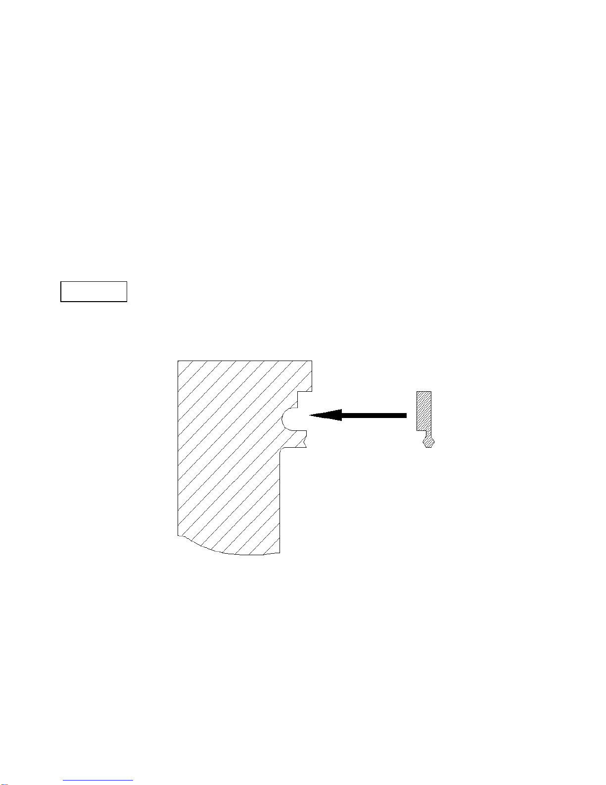
- Install joint ring (39) to front cover (38).
Note: Joint Ring (39) must be installed the right way round, see Fig 46.
The Joint Ring (39) "clips" into place on the register. Make sure
that the Joint Ring (39) is correctly located around its entire
circumference before proceeding.
Fig 46
- Install front cover (38) to rotorcase (40) (noting that it locates onto
dowels (80)), securing with dome nuts (36), tightening to correct torque,
refer to section 5.2. Make certain that the joint ring (39) is not dislodged
from its correct position during the installation operation.
- Install new split pins (82) through castellations of castle nuts (81) and
drilled holes in rotor (41) draw bolts. It may be found necessary to
loosen castellated nut (81) fractionally to align holes. Bend ends of
split-pins (82) over to secure, ensuring that ends will not interfere with
drive coupling hub when it is reinstalled to drive shaft (9).
WWAARRNNIINNGG
Page 50
Page 50
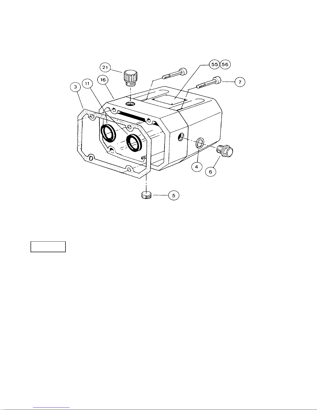
4.4.6 Gearbox Cover Assembly
Fig 47
- Install lipseals (11) to gearbox cover (16).
- Install breather (21); drain plugs (5) and sight glass (6) in required
position in gearbox cover (16).
Note: The sight glass (6) must be installed in the upper tapped hole in the
side of the gearbox cover (16). Remember to fill the gearbox with
oil prior to start up. For recommended lubricant capacities and
grades refer to section 5.3.
- Install gearbox cover (16) with gasket (3) to rotorcase (40) securing
with screws (7), tightening to correct torque, refer to section 5.2.
WWAARRNNIINNGG
Page 51

Page 51
4.5 Mechanical Seal Installation and Removal
4.5.1 Procedures for Installing Mechanical Seals
"Quick summary" of mechanical seal installation.
- Mechanical seals are precision-engineered assemblies incorporating
finely lapped seal faces and seats. They must therefore be handled
with care and will not give optimum performance unless installed
carefully and according to instructions.
- Where mechanical seals are to be re-used ensure seal components are
kept in their appropriate sets.
- Do not mix old and new seal faces on the same seal.
- Remove any sharp corners and burrs that may damage any elastomers
such as o rings or lip seals.
- Ensure that all seal component installation bores and housings are
thoroughly cleaned before installation.
- The seal faces and seats must be handled with care and cleaned
thoroughly before installation.
- Ensure that seal faces are undamaged and that the o rings, Squad
rings (position 30) and L-Cups (position 32) are not cut, swollen or
cracked. It is recommended that new Squad rings are installed each
time that the static seal faces are removed from the rotorcase and that
new L-Cups are installed each time that the rotary seal faces are
removed from the rotors.
- All elastomeric components should be lightly lubricated with a suitable
lubricant before installing, but ensure there is no excessive amount of
lubricant especially around the seal face area.
- When cleaning seal faces with solvent based cleaner, avoid getting
solvent onto rubber components.
- Ensure static seal faces are mounted squarely in the rotorcase and the
rotary seal faces are mounted squarely in the rotors.
- Do not use any excessive force to install a mechanical seal. If it is
difficult to position and assemble the seal then something is wrong.
- If you drop or damage a seal, do not install it before an inspection has
been carried out.
- Do not run a mechanical seal dry.
WWAARRNNIINNGG
Page 52
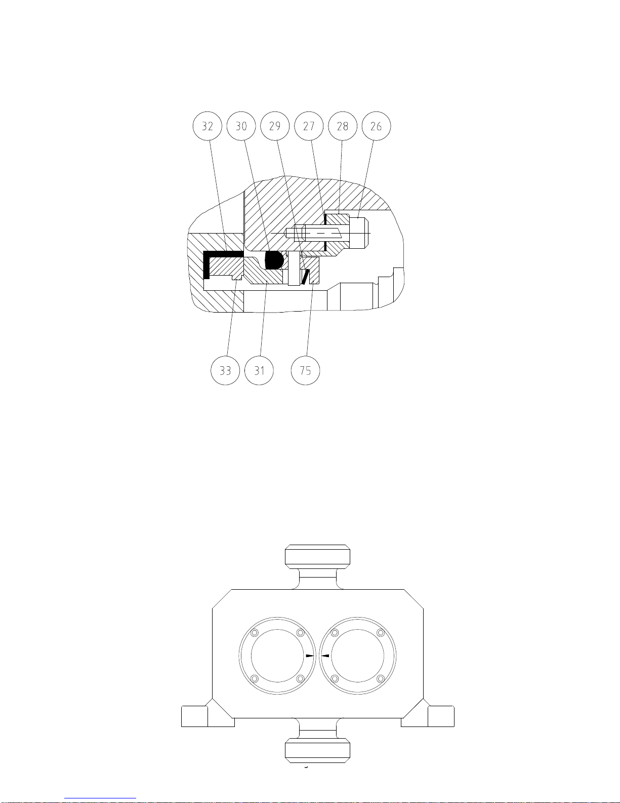
Page 52
4.5.2 Single Mechanical Seal
Fig 48
- Read the General Procedures to prepare for seal installation, refer to
section 4.5.1.
- If only the seal faces are being replaced, the seal housings (28) and
gaskets (27) or o rings (27) will already be in place.
- Install seal housings (28) with gasket (27) on SQ1 and SQ2 models or
o ring (27) on SQ3 and SQ4 models to rotorcase (40) ensuring arrows
on seal housings (28) align, see Fig 49, securing with screws (26)
tightened to correct torque, refer to section 5.2.
Fig 49
Page 53
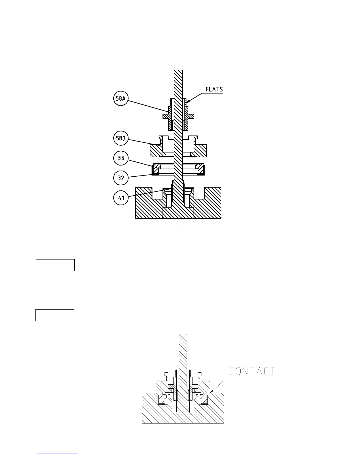
Page 53
- Install rotary seal faces (33) into L-Cups (32).
- Install L-Cups (32) with rotary seal faces (33) into rotors (41) using tools
(58A & 58B) see Fig 50.
The correct method is as follows:
- Position rotary seal face (33) and L-Cup (32) assembly into place over
counterbore in rotor (41). Install tool (58B) so that flat face of tool (58B)
abuts against working face of rotary seal face (33). Slide tool (58A) over
rotor (41) draw bolt such that spanner-flats are outermost and internal
thread in tool (58A) engages with external thread inside rotor (41).
Screw tool (58A) in until its driving face abuts with tool (58B), then
continue screwing until rotary seal face (33) and L-Cup (32) assembly
has been pushed fully into place. This is achieved when face of tool
(58B) contacts rear face of rotor (41), see fig 51.
Note: Extreme care should be taken when carrying out these procedures
to ensure that the seal faces are not damaged. No excessive force
is necessary if the extraction tools are used correctly.
Fig 51
Fig 50
WWAARRNNIINNGG
WWAARRNNIINNGG
Page 54
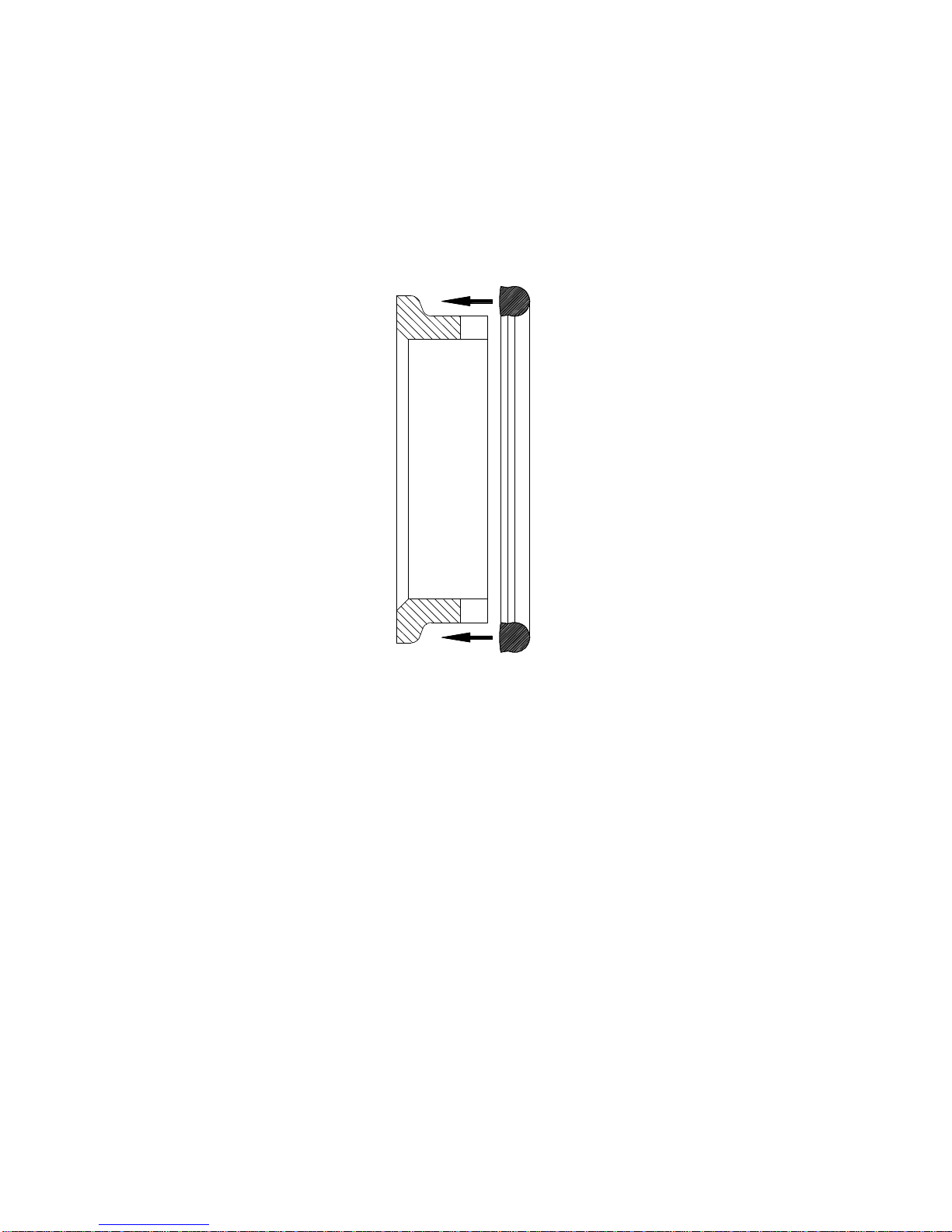
Page 54
- Remove tools (58A & 58B).
- Make sure the L-cups (32) are located correctly with the seal faces (33)
sitting squarely in them.
- Install Squad rings (30) to stationary seats (31), ensuring correct
orientation, see Fig 52.
Fig 52
- Install seal carriers (75) to seal housings (28) ensuring drive pins and
slots are correctly engaged.
- Gently push the stationary seat (31) and Squad ring (30) assemblies
into the seal carriers (75), ensuring correct engagement of drive pins
into slots.
- You should now be able to feel the resistance being generated by the
wave springs (29).
- Before final assembly, check that the seal faces are absolutely clean,
use a soft tissue and a suitable solvent based, non-abrasive, cleaner
for best results.
Page 55
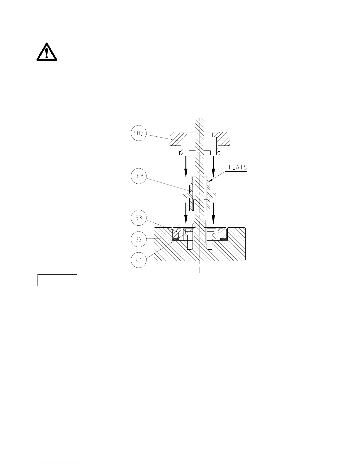
Page 55
Dismantling of Single Mechanical Seals
- Ensure pump is fully shutdown refer to section 3.5.
Note: If seals are being reinstalled, ensure that seal faces remain
matched.
- Remove rotary seal faces (33) from rotors (41) using extraction tools
(58A & 58B). To dismantle, reverse above procedure using extraction
tools supplied to aid in the removal of the seal faces, see Fig 53.
Fig 53
The correct method is as follows:
- Slide tool (58A) over rotor (41)
draw bolt
such that spanner-flats are
outermost and internal thread in tool (58A) engages with external
thread inside rotor (41). Screw tool (58A) in until it is fully home, but DO
NOT TIGHTEN. Install tool (58B) so the lugs of tool (58B) engage into
recesses in rotary seal face (33). Rotate tool (58B) through 90 degrees
such that its driving dogs are located beneath the dogs in inside of
rotary seal face (33). Unscrew tool (58a), whilst holding tool (58b), so
as to cause tool (58B) to pull rotary seal face (33) out of L-Cup (32).
- Remove L-cups (32) from rotors (41).
WWAARRNNIINNGG
WWAARRNNIINNGG
Page 56
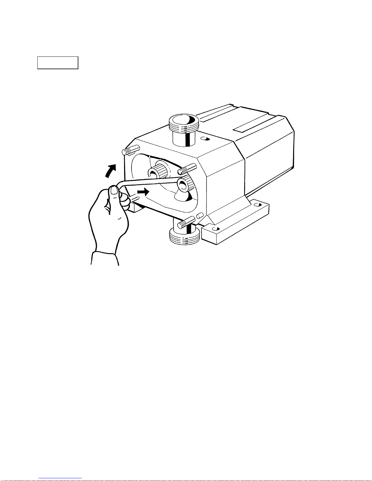
Page 56
- The static faces (31) can be removed by use of tool (58C) see Fig 54.
Note: Extreme care should be taken when carrying out these procedures
to ensure that the seal faces are not damaged. No excessive force
is necessary if the extraction tools are used correctly.
Fig 54
WWAARRNNIINNGG
Page 57
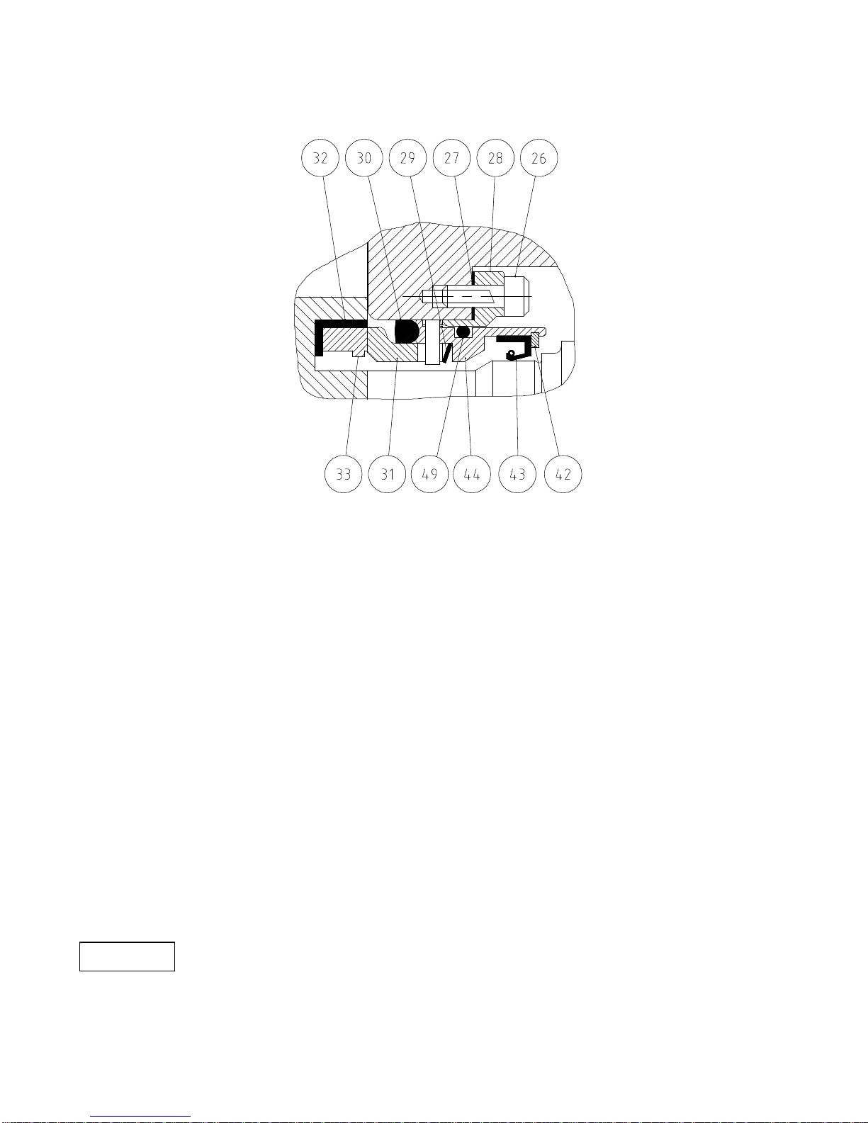
Page 57
4.5.3 Single Mechanical Seal (low-pressure flush / quench).
Fig 55
Read the General Procedures to prepare for seal installation, refer to section 4.5.1
If only the seal faces are being replaced, the housings (28 & 44), lipseals (43) and o-
rings (49) will already be in place.
- Install seal housings (28) with gasket (27) on SQ2 models or o ring (27)
on SQ3 & SQ4 models to rotorcase (40) ensuring arrows on seal
housings (28) align, see Fig 49, securing with screws (26) tightened to
correct torque, refer to section 5.2.
- Install rotary seal faces (33) into L-cups (32).
- Install L-cups (32) with rotary seal faces (33) into rotors (41) using tools
(58A & 58B) see Fig 50.
The correct method is as follows:
- Position rotary seal face (33) and L-Cup (32) assembly into place over
counterbore in rotor (41). Install tool (58B) so that flat face of tool (58B)
abuts against working face of rotary seal face (33). Slide tool (58A) over
rotor (41) draw bolt such that spanner-flats are outermost and internal
thread in tool (58A) engages with external thread inside rotor (41).
Screw tool (58A) in until its driving face abuts with tool (58B), then
continue screwing until rotary seal face (33) and L-Cup (32) assembly
has been pushed fully into place. This is achieved when face of tool
(58B) contacts rear face of rotor (41), see Fig 51.
Note: Extreme care should be taken when carrying out these procedures
to ensure that the seal faces are not damaged. No excessive force
is necessary if the extraction tools are used correctly.
- Remove tools (58A & 58B).
WWAARRNNIINNGG
Page 58
Page 58
- Make sure the L-Cups (32) are located correctly with the seal faces (33)
sitting squarely in them.
- Install Squad rings (30) to stationary seats (31), ensuring correct
orientation, see Fig 52.
- Install lipseals (43) to flushed housings (44), securing in place with
retainers (42).
- Install o-rings (49) to flushed housings (44).
- Install flushed housings (44) to seal housings (28), ensuring correct
location of drive pins into slots.
- Gently push the stationary seat (31) and Squad ring (30) assemblies
into the flushed housings (44), ensuring correct location of drive pins
into slots.
- You should now be able to feel the resistance being generated by the
wave springs (29).
- Before final assembly, check that the seal faces are absolutely clean,
use a soft tissue and a suitable solvent based, non-abrasive, cleaner
for best results.
Dismantling of Single Mechanical Seals for Quench / Flush
Ensure pump is fully shutdown refer to section 3.5.
Note: If seals are being reinstalled, ensure that seal faces remain
matched.
- Remove rotary seal faces (33) from rotors (41) using extraction tools
(58A &58B).
- To dismantle, reverse the above procedure using the extraction tools
supplied to aid in the removal of the seal faces.
The correct method is as follows, see Fig 53.
- Slide tool (58A) over rotor (41) draw bolt such that spanner-flats are
outermost and internal thread in tool (58A) engages with external
thread inside rotor (41). Screw tool (58A) in until it is fully home. DO
NOT TIGHTEN. Install tool (58B) so the lugs of tool (58B) engage into
recesses in rotary seal face (33). Rotate tool (58B) through 90 degrees
such that its driving dogs are located beneath the dogs in inside of
rotary seal face (33). Unscrew tool (58a), whilst holding tool (58b), so
as to cause tool (58B) to pull rotary seal face (33) out of L-Cup (32).
Note: Extreme care should be taken when carrying out these procedures
to ensure that the seal faces are not damaged. No excessive force
is necessary if the extraction tools are used correctly.
- Remove L-cups (32) from rotors (41).
- The static seal faces (31) can be removed by using tool (58C) see Fig 54.
WWAARRNNIINNGG
WWAARRNNIINNGG
Page 59
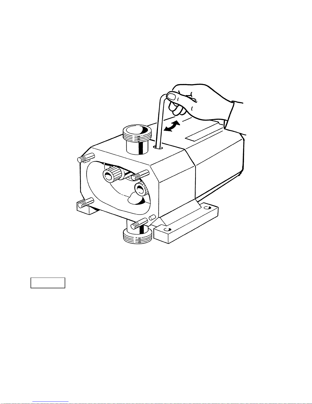
Page 59
- Remove flushed housing / wave spring / lipseal (44 / 29/ 43)
assemblies from shafts (9 & 10). This can be achieved by inserting the
extraction tool (58C) through the drain/leakage detection holes in the
sides of the rotorcase (40) and applying a twisting action, see Fig 56.
Fig 56
- Remove o-rings (49) from flushed housings (44).
- Remove retainers (42) and lipseals (43) from flushed housings (44).
Note: Extreme care should be taken when carrying out these procedures
to ensure that the seal faces are not damaged. No excessive force
is necessary if the extraction tools are used correctly.
WWAARRNNIINNGG
Page 60
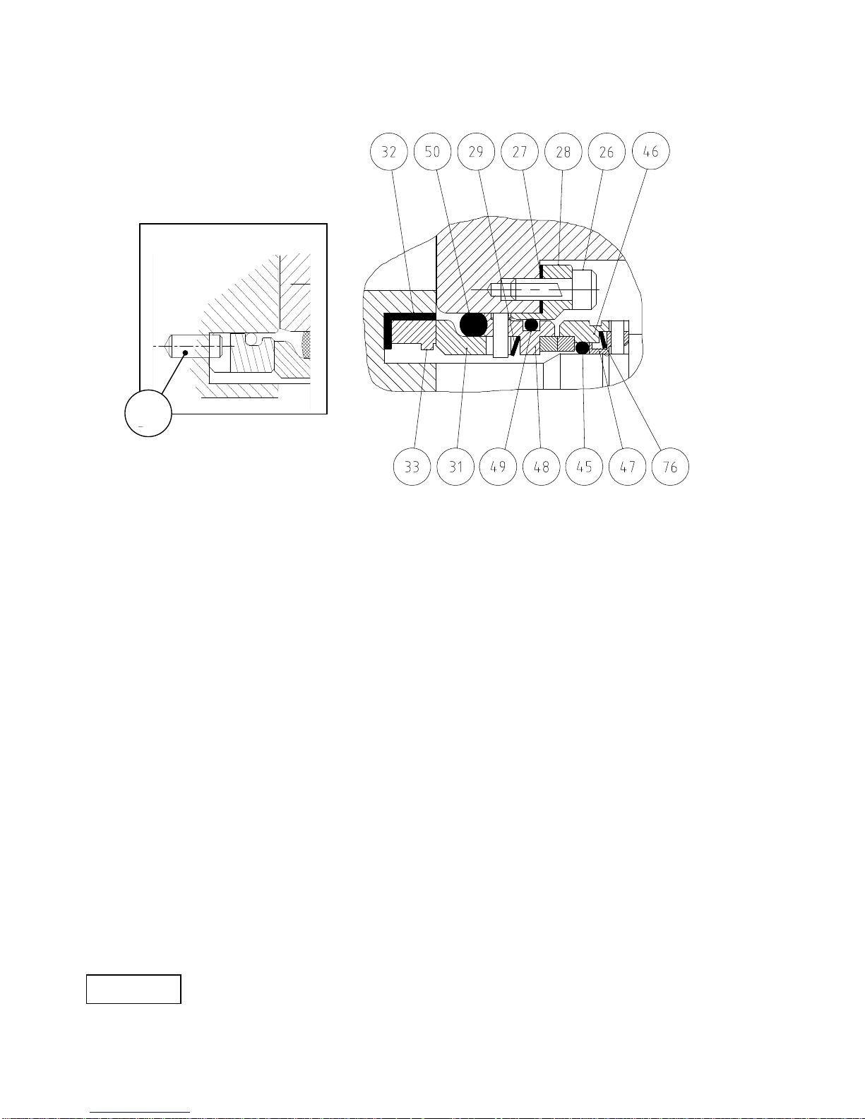
Page 60
4.5.4 Double Mechanical Seal (high-pressure flush).
Fig 57
Read the General Procedures to prepare for seal installation, refer to section 4.5.1.
If only the seal faces are being replaced, the seal housings (28) and gaskets (27) will
already be in place.
- Install seal housings (28) with gasket (27) on SQ2 models or o ring (27)
on SQ3 & SQ4 models to rotorcase (40) ensuring arrows on seal
housings (28) align, see Fig 46, securing with screws (26) tightened to
correct torque, refer to section 5.2.
- Install rotary seal faces (33) into L-cups (32), where pin drive option is
available, ensure the anti-rotation pin is aligned with hole provided in
rotor. Once installed the seal face should be level with the rotor.
- Install L-cups (32) with rotary seal faces (33) into rotors (41) using tools
(58A & 58B) see Fig 50.
The correct method is as follows:
Position rotary seal face (33) and L-Cup (32) assembly into place over
counterbore in rotor (41). Install tool (58B) so that flat face of tool (58B) abuts
against working face of rotary seal face (33). Slide tool (58A) over rotor (41)
draw bolt such that spanner-flats are outermost and internal thread in tool
(58A) engages with external thread inside rotor (41). Screw tool (58A) in until
its driving face abuts with tool (58B), then continue screwing until rotary seal
face (33) and L-Cup (32) assembly has been pushed fully into place. This is
achieved when face of tool (58B) contacts rear face of rotor (41), see Fig 51.
Note: Extreme care should be taken when carrying out these procedures
to ensure that the seal faces are not damaged. No excessive force
is necessary if the extraction tools are used correctly.
WWAARRNNIINNGG
RRoottaarryy PPiinn DDrriivvee
33
Page 61

Page 61
- Remove tools (58A & 58B).
- Make sure the L-Cups (32) are located correctly with the seal faces (33)
sitting squarely in them.
- Install housing / wave spring (47/76) assemblies to rotorcase (40)
ensuring correct engagement of drive pins into slots in shafts (9 and
10).
- Install o-rings (45) into outboard rotary seal faces (46) and then install
to shafts (9 and 10) ensuring engagement of slots with pins in housings
(47).
- You should now be able to feel the resistance being generated by the
wave springs (76).
- Install o-rings (49) to seal cartridges (29/48).
- Clean faces of outboard seal (46 and 48) use a soft tissue and a
suitable solvent based, non-abrasive, cleaner for best results.
- Install seal cartridge assemblies (comprising parts 29, 48 and 49) onto
shafts (9 and 10) and push in until outboard seal faces (46) and (48)
mate - ensuring engagement of pins with slots in housings (28). Take
care not to damage the o rings (49).
Note: Extreme care should be taken when carrying out these procedures
to ensure that the seal faces are not damaged. No excessive force
is necessary if the extraction tools are used correctly.
- Install Squad rings (30) (ensuring correct orientation, see Fig 52) or o
rings (50) to stationary seats (31). Refer to section 4.5.7 for details of
pressure limitations of parts (30) and (50).
- Gently push the stationary seat (31) and Squad ring (30) or o-ring (50)
assemblies into the housings (44), ensuring correct location of drive
pins into slots.
- You should now be able to feel the resistance being generated by the
wave springs (29) in addition to that being generated by wave springs
(76).
- Before final assembly, check that the seal faces are absolutely clean,
use a soft tissue and a suitable solvent based, non-abrasive, cleaner
for best results.
WWAARRNNIINNGG
Page 62

Page 62
Dismantling of Double Mechanical Seals for Flush
Ensure pump is fully shutdown refer to section 3.5.
Note: If seals are being reinstalled, ensure that seal faces remain
matched.
- Remove rotary seal faces (33) from rotors (41) using extraction tools
(58A & 58B).
- To dismantle, reverse the above procedure using the extraction tools
supplied to aid in the removal of the seal faces.
The correct method is as follows, see fig 53:
Slide tool (58A) over rotor (41) draw bolt
such that spanner-flats are outermost
and internal thread in tool (58A) engages with external thread inside rotor (41).
Screw tool (58A) in until it is fully home. DO NOT TIGHTEN. Install tool (58B)
so that lugs of tool (58B) engage into recesses in rotary seal face (33). Rotate
tool (58B) through 90 degrees such that its driving dogs are located beneath
the dogs in inside of rotary seal face (33). Unscrew tool (58a), whilst holding
tool (58b), so as to cause tool (58B) to pull rotary seal face (33) out of L-Cup
(32).
Note: Extreme care should be taken when carrying out these procedures
to ensure that the seal faces are not damaged. No excessive force
is necessary if the extraction tools are used correctly.
- Remove L-cups (32) from rotors (41).
- The static seal faces (31) can be removed by use of tool (58C) see Fig
54.
- Remove stationary seal cartridge assemblies (29, 48 and 49) from the
shafts (9 and 10) by pulling off.
- Remove o-rings (49) from seal cartridges (29/48).
- Remove rotary seal faces (46) and housing / wave-spring (47/76)
assemblies from shafts (9 & 10). This can be achieved by inserting the
extraction tool (58c) through the drain/leakage detection holes in the
sides of the rotorcase (40) and applying a twisting action, see Fig 56.
Note: Extreme care should be taken when carrying out these procedures
to ensure that the seal faces are not damaged. No excessive force
is necessary if the extraction tools are used correctly.
- Remove o-rings (45) from rotary seal faces (46).
WWAARRNNIINNGG
WWAARRNNIINNGG
WWAARRNNIINNGG
Page 63
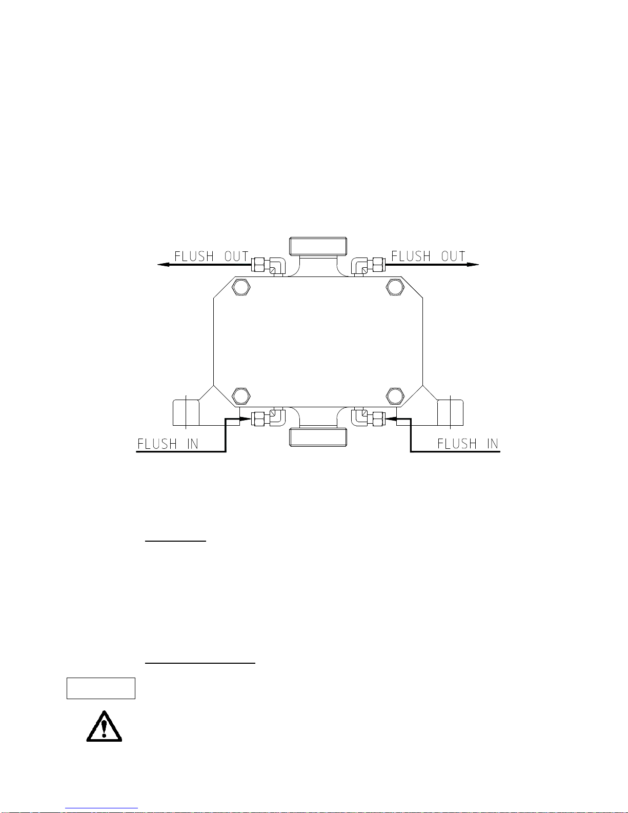
Page 63
4.5.5 Mechanical Seals for Quench or Flush - Auxiliary Services
Every Concept SQ pump is provided with four seal flushing connections, two
on each side of the rotorcase, which are tapped 1/8" BSP.
Pumps supplied with mechanical seals requiring an auxiliary flush have an
elbow adapter terminating in compression joint to accept 1/4" diameter
pipework installed to each flushing connection. There are two flushing
connections for each seal, one for flush 'in', the other for flush 'out', see Fig 58
and the pipework for the flush should be arranged to provide an independent
flush to each seal.
Fig 58
Pumps supplied with a mechanical seal not requiring an auxiliary flush have
blanking plugs in each flushing connection. Should the pump be converted to
a flushed mechanical seal after original supply these plugs can be removed
and the flush connections used to provide the appropriate flush.
Terminology.
"Quench"
- To provide a liquid barrier, which is not, induced to flow through
the seal area by any external means.
"Flush"
- To provide a liquid barrier, which is, induced to flow through the
seal area by an external means.
Quench or Flush Media
The media used for quenching or flushing a seal must be fully compatible with
the pumped media, and the materials of construction of pump and seal.
Special consideration must be given to the temperature limitations of the media
to ensure that no hazards are created, e.g. risk of fire or explosion.
WWAARRNNIINNGG
Page 64
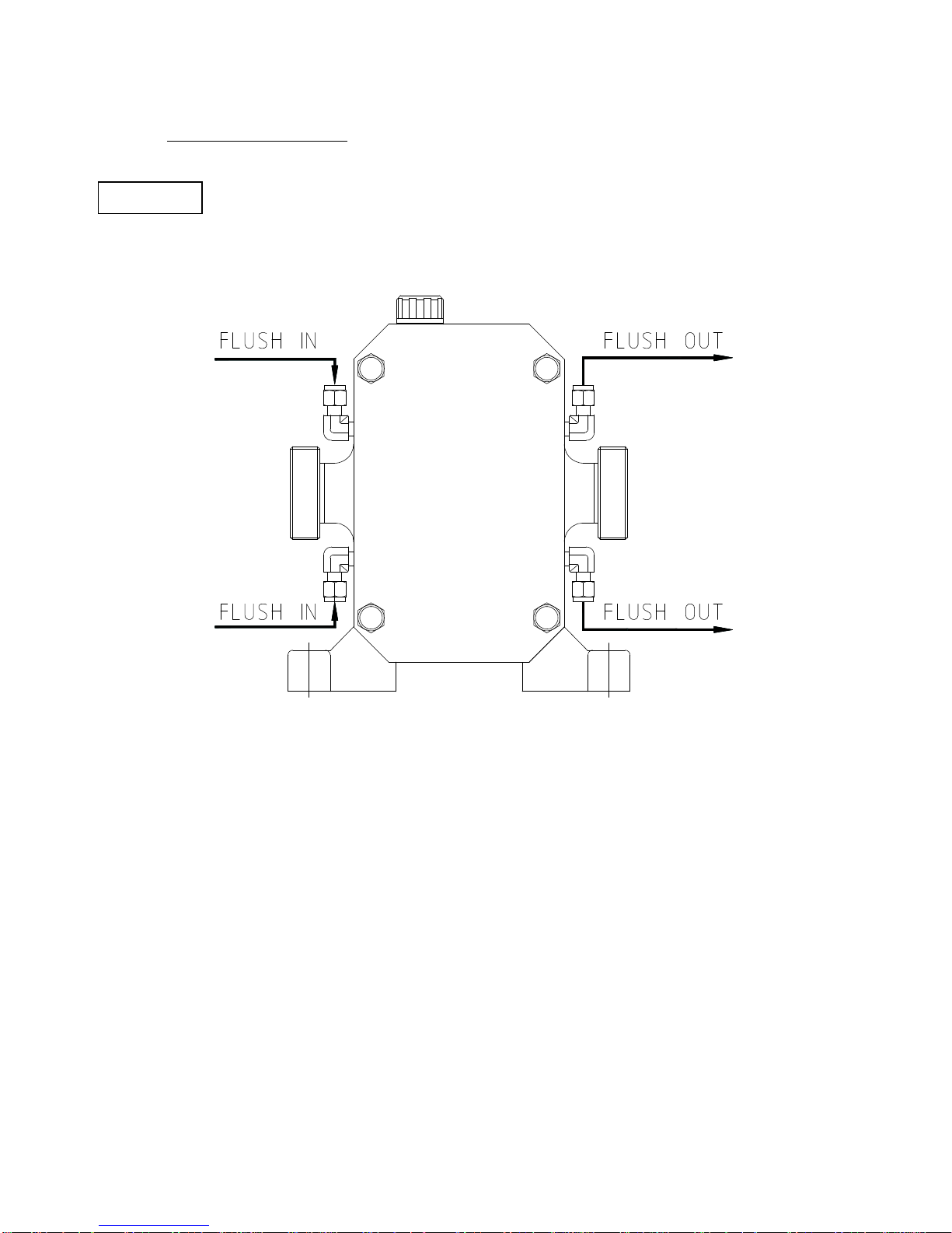
Page 64
Venting of Seal Housings
When starting up an SQ pump which is equipped with a quenched or flushed
mechanical seal, and which is mounted with the rotorcase port connections in
the horizontal plane, see Fig 59. The pump should be run for a few minutes
with the quench / flush media being caused to flow at a rate of approximately 5
litres per minute. This will allow for venting of the seal housings.
Fig 59
After this initial period of running, the flush flow rate and pressure should be
regulated.
WWAARRNNIINNGG
Page 65

Page 65
Single Mechanical Seal for Quench / Flush (For low-pressure Quench or Flush)
Refer to section 4.3.3.
This seal arrangement requires a supply of media to the outboard side of the
mechanical seal to quench or flush the seal area. The nature of the pumped
media and the specific duty conditions will determine whether a quench or a
flush is required.
A quench provides a static head. The quench media vessel should be mounted
a minimum of 0.5 metres above the pump, preferably directly above the seal
area. The interconnecting pipework should be as straight as possible, avoiding
horizontal runs, and with the minimum number of bends and restrictions.
For a suitable flush, the media must be supplied at a flow rate of 3 litres per
minute per shaft seal.
Note: The limiting flush or quench pressure in any application is 0.5 bar
Double Mechanical Seal for Flush (For High Pressure Flush).
Refer to section 4.3.4.
This seal arrangement requires a supply of media to be circulated between the
inboard and outboard mechanical seals. The flush media must be supplied at a
flow rate of 3 litres per minute per shaft seal assembly.
The flush pressure must be a minimum of 1 bar greater than the maximum
discharge pressure created by, or the maximum suction pressure applied to,
the pump whichever is the greater.
Note: Where the Double Mechanical Seal is installed with o-ring (50), the
limiting flush pressure in any application is 16 bar g.
Where the Double Mechanical Seal is installed with Squad ring (30),
the maximum differential pressure that can be allowed to occur
between the pumped media and the flush media is 5 Bar.
WWAARRNNIINNGG
WWAARRNNIINNGG
Page 66
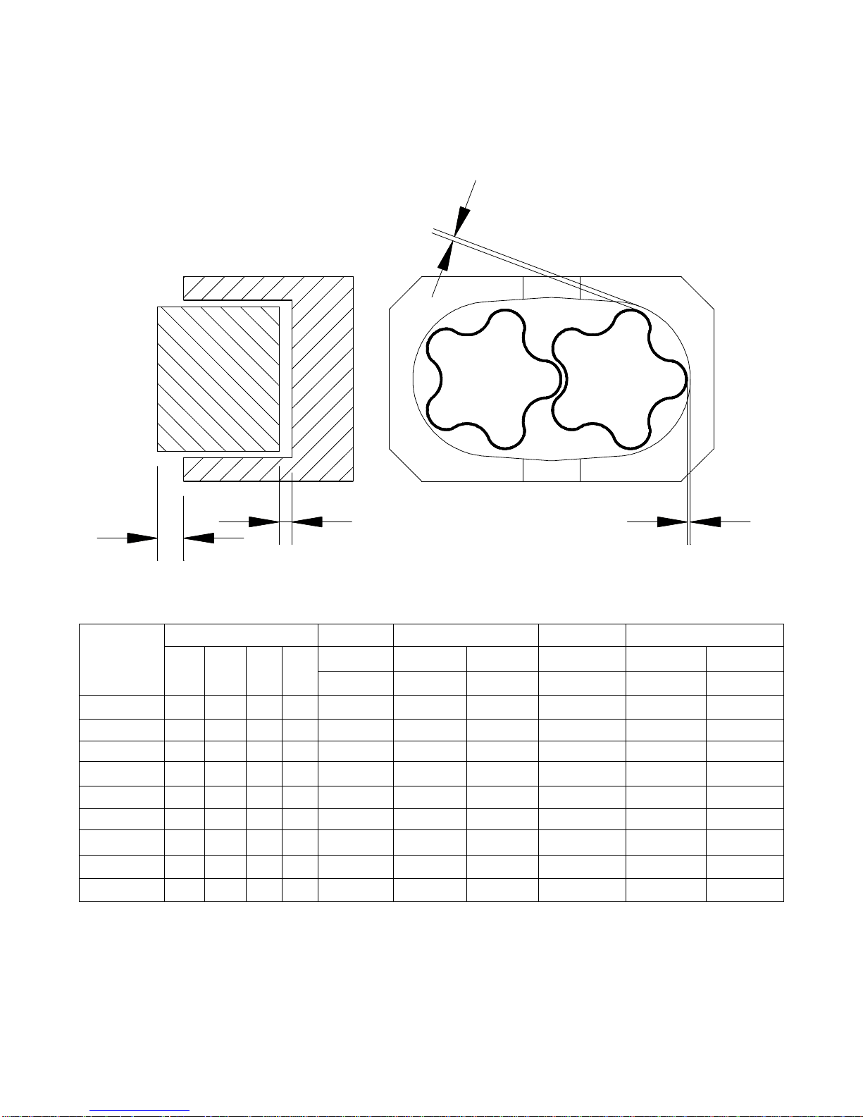
Page 66
5.0 Specifications
5.1 Clearance Chart
CONCEPT
SQ
MODEL
MAXIMUM
MILLIMETRES
x 0.01
INCHES
x 0.001
Bar PSI
°°°°C °°°°F
FRONT REAR RADIAL FRONT REAR RADIAL
A B C A B C
SQ1/0004/12
12 175 150 300 5.91 - 5.94 6 - 15 7 - 16 0.233 - 0.234 2.4 - 5.9 2.7 - 5.9
SQ1/0007/06
6 85 150 300 5.88 - 5.91 8 - 18 10 - 19 0.231 - 0.233 3.1 - 7.1 3.9 - 7.5
SQ2/0017/15
15 215 150 300 7.85 - 7.87 10 - 20 11 - 22 0.309 - 0.310 3.9 - 7.8 4.3 - 8.7
SQ2/0030/07
7 100 150 300 7.84 - 7.86 11 - 21 13 - 25 0.308 - 0.309 4.3 - 8.3 5`1 - 9.8
SQ3/0054/15
15 215 150 300 4.83 - 4.85 15 - 26 14 - 30 0.190 - 0.191 5.9 - 10.2 5.5 - 11.8
SQ3/0103/07
7 100 150 300 4.81 - 4.83 17 - 29 17 - 33 0.189 - 0.190 6.7 - 11.4 6.7 - 12.9
SQ4/0160/15
15 215 150 300 6.69 - 6.71 23 - 36 26 - 47 0.263 - 0.264 9.0 - 14.1 10.2 - 18.5
SQ4/0303/07
7 100 150 300 6.64 - 6.66 25 - 40 30 - 51 0.261 - 0.262 9.8 - 11.6 11.8 - 20.0
SQ4/0303/07
7 100 180 356 6.50 – 6.55 32 - 44 35 - 48 0.260 - 0.262 12.60 -17.32 13.77 -18.89
A
B
C
C
Page 67

Page 67
5.2 Fixings & Torque Settings
Notes: 1.0) Rolling torque quoted for nut, item 12 (reference section 4.2.1).
2.0) For positions of items see section 5.6, Typical Basic Pump
Build.
CONCEPT SQ MODEL
SQ1/0004/12 SQ2/0017/15 SQ3/0054/15 SQ4/0160/15
ITEM DESCRIPTION POSITION
SQ1/0007/06 SQ2/0030/07 SQ3/0103/07 SQ4/0303/07
2
SOCKET FOOT /
QUANTITY/PUMP
4 4 4 4
HEAD CAP SCREW ROTORCASE
SIZE - mm
M8 X 12 M10 X 16 M10 X 20 M16 X 25
TORQUE - N.M (ft-lb).
17 12.54 30 22.13 30 22.13 140 103.26
7
SOCKET GEARBOX /
QUANTITY/PUMP
4 4 4 4
HEAD CAP SCREW ROTORCASE
SIZE – mm
M6 X 50 M8 X 50 M10 X 50 M10 X 55
TORQUE - N.M (ft-lb).
7 5.16 17 12.54 30 22.13 30 22.13
12
LOCK NUT BEARING /
QUANTITY/PUMP
2 2 2 2
SHAFT
SIZE - mm
M20 X 1.0 M35 X 1.5 M45 X 1.5 M65 X 2.0
(SEE 1.0)
ROLLING TORQUE - N.M
(ft-lb).
1.0 - 1.5 2.0 - 2.5 3.0 - 3.5 5.5 - 6.0
(0.75 – 1.11) (1.46 – 1.85) (2.21 – 2.58) (4.06 – 4.43)
23
SOCKET BEARING SLV /
QUANTITY/PUMP
6 - - -
HEAD CAP SCREW MOUNTING PLT
SIZE - mm
M6 x 20 - - -
TORQUE - N.M (ft-lb).
16 11.80 - - -
23
SOCKET BEARING SLV /
QUANTITY/PUMP
- 6 6 6
HEAD CAP SCREW ROTORCASE
SIZE - mm
- M8 X 30 M12 X 50 M16 X 55
TORQUE - N.M (ft-lb).
- 25 18.44 80 59.00 140 103.26
26
SOCKET HOUSING /
QUANTITY/PUMP
8 8 8 12
HEAD CAP SCREW ROTORCASE
SIZE - mm
M4 X 8 M5 X 12 M6 X 16 M8 X 20
TORQUE - N.M (ft-lb).
5 3.69 6 4.43 8 5.90 17 12.54
36 DOME NUT
FRONT COVER /
QUANTITY/PUMP
4 4 4 8
ROTORCASE
SIZE - mm
M8 M10 M12 M12
TORQUE - N.M (ft-lb).
17 12.54 30 22.13 55 40.57 55 40.57
37 STUD
FRONT COVER /
QUANTITY/PUMP
4 4 4 8
ROTORCASE
SIZE - mm
M8 X 36 M10 X 43 M10 X 57 M12 X 65
TORQUE - N.M (ft-lb).
17 12.54 30 22.13 30 22.13 55 40.57
56 HAMMER DRIVE
NAMEPLATE /
QUANTITY/PUMP
4 4 4 4
GEARBOX
SIZE - mm
- - - -
TORQUE - N.M (ft-lb).
- - - -
74
SOCKET MOUNTING PLT/
QUANTITY/PUMP
4 - - -
HEAD CAP SCREW GEARBOX
SIZE - mm
M6 X 20 - - -
TORQUE - N.M (ft-lb).
16 11.80 - - -
81 CASTLE NUT
DRAWBOLT /
QUANTITY/PUMP
2 2 2 2
SHAFT
SIZE - mm
M6 M12 M16 M20
TORQUE - N.M (ft-lb).
10 7.38 50 36.88 90 66.38 130 95.88
82 SPLIT PIN
CASTLE NUT /
QUANTITY/PUMP
2 2 2 2
SHAFT
SIZE - mm
1/16" X 1/2" 1/8" X 3/4" 1/8" X 1" 5/32" X 1 1/4"
TORQUE - N.M (ft-lb).
- - - -
88
TORQUE LOCK
ASSEMBLY
TIMING GEAR /
QUANTITY/PUMP
6 - - -
SHAFT
SIZE - mm
- - - -
TORQUE - N.M (ft-lb).
2 1.48 - - -
Page 68
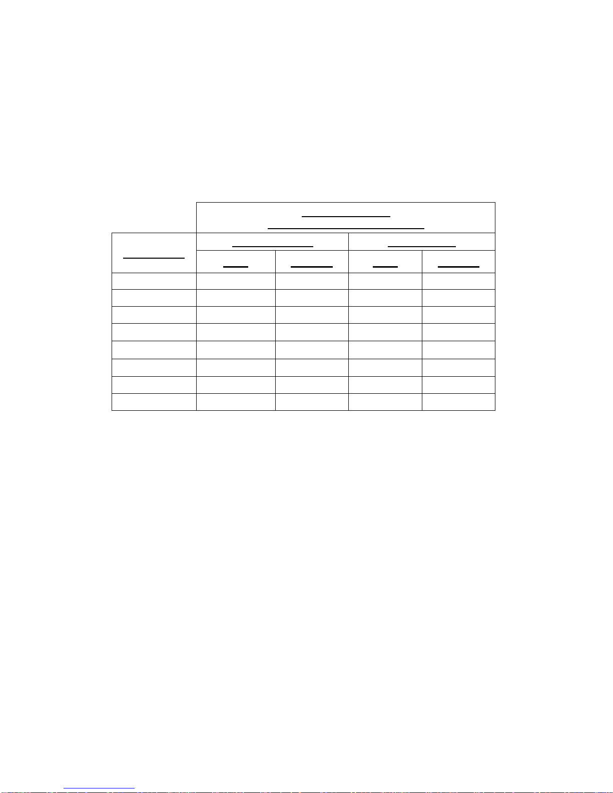
Page 68
5.3 Lubricants
Gearbox oil recommended for use with Concept SQ pumps is an “EP (Extreme
Pressure) grade gear lube” for the following ambient temperature ranges.
EP150 0 – 32°F
EP220 32 – 85°F
EP320 85°F and higher
Approximate pump gearbox capacities for SQ pumps:
Mounting Attitude
Suction and Discharge ports in:
Pump Model
Horizontal Plane Vertical Plane
litres US pints litres US pints
SQ1/0004/12
0.3 0.6 0.3 0.6
SQ1/0007/06
0.3 0.6 0.3 0.6
SQ2/0017/15
1.1 2.4 1.1 2.4
SQ2/0030/07
1.1 2.4 1.1 2.4
SQ3/0054/15
3.0 6.3 2.55 5.4
SQ3/0103/07
3.0 6.3 2.55 5.4
SQ4/0160/15
7.55 16.0 5.7 12.0
SQ4/0303/07
7.55 16.0 5.7 12.0
Always add oil to the level of the sight glass. The sight glass must be located in the
uppermost position on the side of the gearbox cover. DO NOT OVERFILL.
5.4 Material Specification.
Rotors 316L Stainless Steel
Rotorcase 316L Stainless Steel
Shafts 316L Stainless Steel
Front Cover 316L Stainless Steel
Rotor Retainer 316L Stainless Steel
Gearbox Cover Grade 220 Grey Cast Iron or 316 Stainless Steel
Bearing Sleeve 070 M20 Steel - S1, S2 & S3
For Grade 220 Grey Cast Iron – S4
Page 69
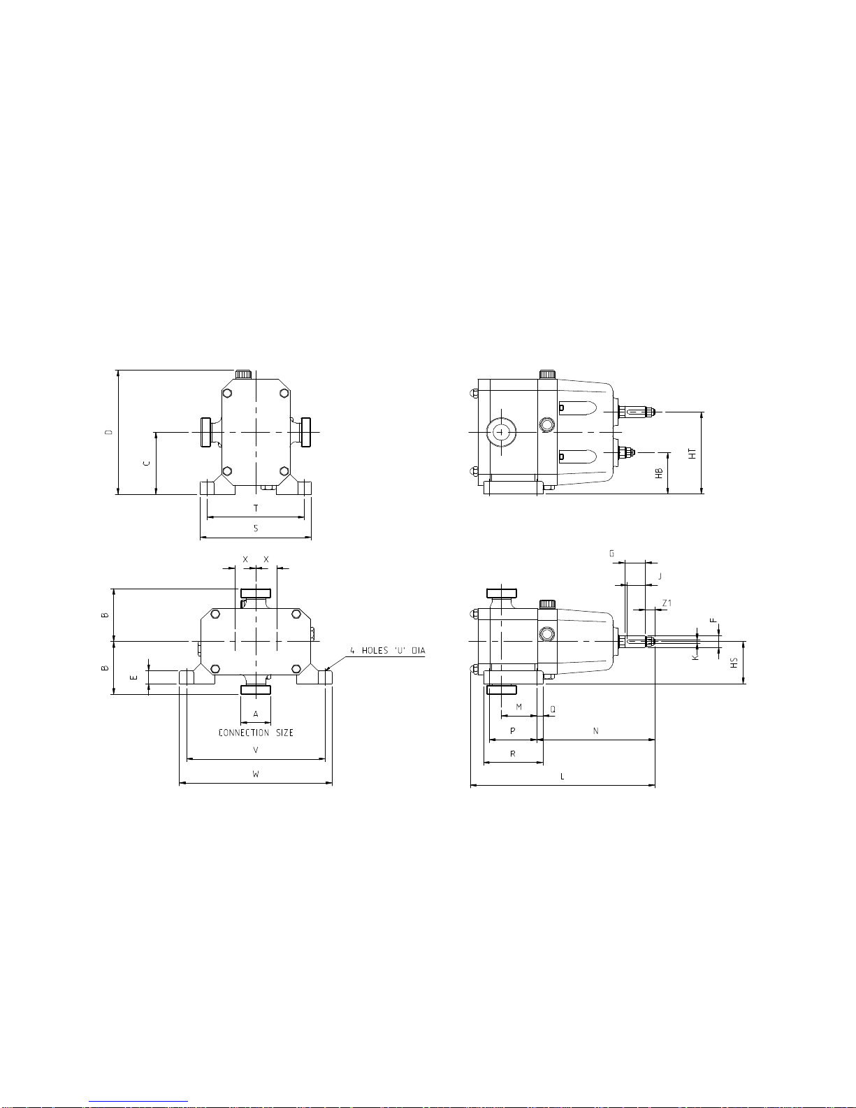
Page 69
5.5 Concept SQ Range Foundation Dimensions and Weights
Page 70

Page 70
MODEL A B1 B2 B3 B4 B5 C D E F G HB HS HT J K L M N P Q R S T U V W X Z1
Weight
(kgs)
SQ1/0004/12
25 86 104 100 107 148 84.5 176 17 16 j6 28 57 57 112 24 5 253 41 168 62 8 78 146 128 9 183 201 27.5 11 12.9
SQ10007/06
25 86 104 100 107 148 84.5 176 17 16 j6 28 57 57 112 24 5 270 56 168 62 8 78 146 128 9 183 201 27.5 11 13.4
SQ2/0017/15
40 107 129 121 128 169 118 246 21 28 j6 42 75 75 160 38 8 363 65 230 90 14 117 197 170 11 255 282 42.5 22 35.3
SQ2/0030/07
50 107 129 121 128 169 118 246 21 28 j6 42 75 75 160 38 8 391 87 230 90 14 117 197 170 11 255 282 42.5 22 40.3
SQ3/0054/15
50 131 153 145 152 193 157 324 29 38 k6 80 100 100 215 70 10 482 83 315 124 14 152 243 214 13 329 358 57.5 27 83.0
SQ3/0103/07
80 131 165 145 162 213 157 324 29 38 k6 80 100 100 215 70 10 527 115 315 124 14 152 243 214 13 329 358 57.5 27 91.0
SQ4/0160/15
80 178 208 192 209 260 216 442 30 60 m6 140 136 147 296 129 18 652 109 416 170 16 202 378 342 18 480 516 80.0 34 219.0
SQ4/0303/07
100 182 198 192 199 250 216 442 30 60 m6 140 136 147 296 129 18 714 151 416 170 16 202 378 342 18 480 516 80.0 34 266.0
MODEL A B1 B2 B3 B4 B5 C D E
F
(mm)
G HB HS HT J
K
(mm)
L M N P Q R S T U V W X Z1
Weight
(lbs)
SQ1/0004/12
1.00 3.39 4.09 3.94 4.21 5.83 3.33 6.93 0.67 16 j6 1.10 2.24 2.24 4.41 0.94 5 9.96 1.61 6.61 2.44 0.31 3.07 5.75 5.04 0.35 7.20 7.91 1.08 0.43 28
SQ10007/06
1.00 3.39 4.09 3.94 4.21 5.83 3.33 6.93 0.67 16 j6 1.10 2.24 2.24 4.41 0.94 5 10.6 2.2 6.61 2.44 0.31 3.07 5.75 5.04 0.35 7.20 7.91 1.08 0.43 29
SQ2/0017/15
1.50 4.21 5.08 4.76 5.04 6.65 4.65 9.69 0.83 28 j6 1.65 2.95 2.95 6.30 1.50 8 14.3 2.56 9.06 3.54 0.55 4.61 7.76 6.69 0.43 10.04 11.10 1.67 0.87 78
SQ2/0030/07
2.00 4.21 5.08 4.76 5.04 6.65 4.65 9.69 0.83 28 j6 1.65 2.95 2.95 6.30 1.50 8 15.4 3.43 9.06 3.54 0.55 4.61 7.76 6.69 0.43 10.04 11.10 1.67 0.87 89
SQ3/0054/15
2.00 5.16 6.02 5.71 5.98 7.6 6.18 12.76 1.14 38 k6 3.15 3.94 3.94 8.46 2.76 10 19 3.27 12.4 4.88 0.55 5.98 9.57 8.43 0.51 12.95 14.09 2.26 1.06 183
SQ3/0103/07
3.00 5.16 6.5 5.71 6.38 8.39 6.18 12.76 1.14 38 k6 3.15 3.94 3.94 8.46 2.76 10 20.7 4.53 12.4 4.88 0.55 5.98 9.57 8.43 0.51 12.95 14.09 2.26 1.06 200
SQ4/0160/15
3.00 7.01 8.19 7.56 8.23 10.2 8.50 17.40 1.18 60 m6 5.51 5.35 5.79 11.65 5.08 18 25.7 4.29 16.4 6.69 0.63 7.95 14.88 13.46 0.71 18.90 20.31 3.15 1.34 482
SQ4/0303/07
4.00 7.01 7.8 7.56 7.83 9.84 8.50 17.40 1.18 60 m6 5.51 5.35 5.79 11.65 5.08 18 28.1 5.94 16.4 6.69 0.63 7.95 14.88 13.46 0.71 18.90 20.31 3.15 1.34 585
Dimensions in Inches (except F and K)
Dimensions in Millimetres
B1 applies for Triclamp & thread connections.
B2 applies for DIN Aseptic Connections.
B3 applies for DIN 2633 Flanges.
B4 applies for DIN Aseptic Flanges.
B5 applies for Barrier DIN Aseptic Connections (Male &
Notes: Dimensions given are for guidance only and
should not be used for installation purposes.
Certified dimensions will be supplied on request
Page 71
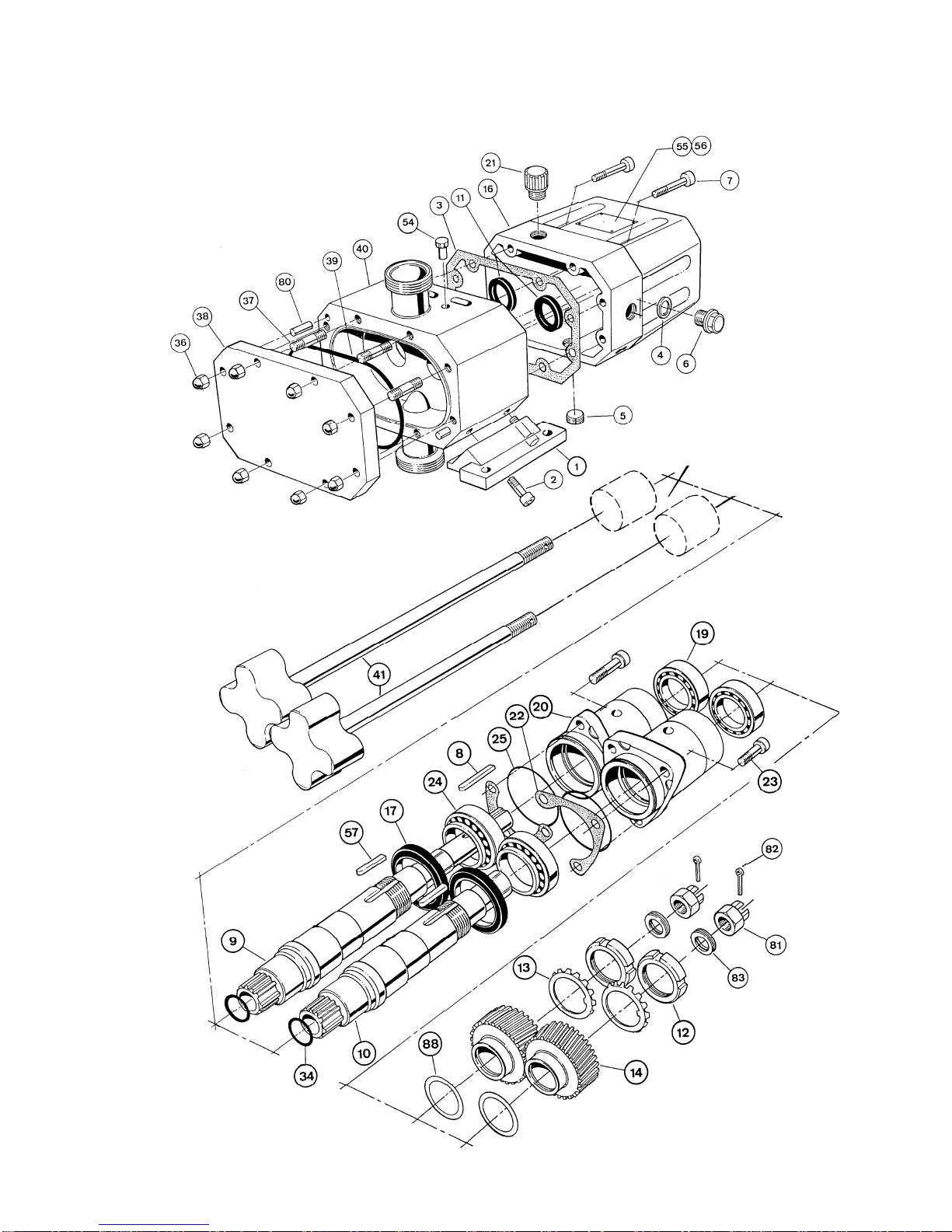
Page 71
5.6 Typical Basic Pump Build
Refer to Section
4.5, Mechanical Seal
Installation and Removal
Page 72

Page 72
5.7 Fault Finding
N
O
F
LOW
I
RREGULAR
F
LOW
U
NDER
C
APACITY
P
UMP
O
VERHEATS
M
OTOR
O
VERHEATS
E
XCESSIVE
R
OTOR
W
EAR
E
XCESSIVE
S
EAL
W
EAR
N
OISE
/
V
IBRATION
S
EIZURE
P
UMP
S
TALLS
O
N
S
TART
UP
Causes
A
CTION
II
NNCCOORRRREECCTT
D
D
IIRREECCTTIIOONN
O
O
FF
R
R
OOTTAATTIIOON
N
..
R
R
EEVVEERRSSEE
M
M
OOTTOOR
R
..
P
P
UUMMPP
N
N
OOTT
P
P
RRIIMMEED
D
..
E
E
XXPPEELL
G
G
AASS
F
F
RROOMM
S
S
UUCCTTIIOONN
L
L
IINNEE
/
/
P
P
UUMMPP
C
C
HHAAMMBBEERR
&
&
P
P
RRIIMME
E
..
I
I
NNSSUUFFFFIICCIIEENNTT
NNPPSSH
H
A
A
VVAAIILLAABBLLE
E
..
I
I
NNCCRREEAASSEE
S
S
UUCCTTIIOONN
L
L
IINNEE
&
&
S
S
TTAATTIICC
S
S
UUCCTTIIOONN
H
H
EEAADD
D
D
IIAAMMEETTEER
R
.
.
S
S
IIMMPPLLIIFFYY
S
S
UUCCTTIIOONN
L
L
IINNEE
&
&
R
R
EEDDUUCCEE
L
L
EENNGGTTH
H
.
.
R
R
EEDDUUCCEE
P
P
UUMMPP
S
S
PPEEEEDD
&
&
P
P
RROODDUUCCTT
T
T
EEMMPPEERRAATTUURRE
E
..
PP
RROODDUUCCTT
V
V
AAPPOORRIISSIINNGG
I
I
NN
S
S
UUCCTTIIOONN
L
L
IINNE
E
..
A
A
IIRR
E
E
NNTTEERRIINNGG
S
S
UUCCTTIIOONN
L
L
IINNE
E
..
R
R
EEMMAAKKEE
P
P
IIPPEEWWOORRKK
J
J
OOIINNTTS
S
..
G
G
AASS
I
I
NN
S
S
UUCCTTIIOONN
L
L
IINNE
E
..
E
E
XXPPEELL
G
G
AASS
F
F
RROOMM
S
S
UUCCTTIIOONN
L
L
IINNEE
/
/
P
P
UUMMPP
C
C
HHAAMMBBEER
R
..
II
NNSSUUFFFFIICCIIEENNTT
S
S
TTAATTIICC
S
S
UUCCTTIIOONN
H
H
EEAAD
D
..
R
R
AAIISSEE
P
P
RROODDUUCCTT
L
L
EEVVEELL
T
T
OO
I
I
NNCCRREEAASSEE
S
S
TTAATTIICC
S
S
UUCCTTIIOONN
H
H
EEAAD
D
..
P
P
RROODDUUCCTT
V
V
IISSCCOOSSIITTYY
T
T
OOOO
H
H
IIGGH
H
..
D
D
EECCRREEAASSEE
P
P
UUMMPP
S
S
PPEEEEDD
/
/
I
I
NNCCRREEAASSEE
P
P
RROODDUUCCTT
T
T
EEMMPPEERRAATTUURRE
E
..
P
P
RROODDUUCCTT
V
V
IISSCCOOSSIITTYY
T
T
OOOO
L
L
OOW
W
..
I
I
NNCCRREEAASSEE
P
P
UUMMPP
S
S
PPEEEEDD
/
/
I
I
NNCCRREEAASSEE
P
P
RROODDUUCCTT
T
T
EEMMPPEERRAATTUURRE
E
..
PP
RROODDUUCCTT
T
T
EEMMPPEERRAATTUURREE
T
T
OOOO
H
H
IIGGH
H
..
C
C
OOOOLL
P
P
RROODDUUCCTT
/
/
P
P
UUMMPPIINNGG
C
C
HHAAMMBBEER
R
..
P
P
RROODDUUCCTT
T
T
EEMMPPEERRAATTUURREE
T
T
OOOO
L
L
OOW
W
..
H
H
EEAATT
P
P
RROODDUUCCTT
/
/
P
P
UUMMPPIINNGG
C
C
HHAAMMBBEER
R
..
U
U
NNEEXXPPEECCTTEEDD
S
S
OOLLIIDDSS
I
I
NN
P
P
RROODDUUCCT
T
C
C
LLEEAANN
S
S
YYSSTTEEMM
/
/
I
I
NNSSTTAALLLL
S
S
TTRRAAIINNEERR
O
O
NN
S
S
UUCCTTIIOONN
S
S
IIDDEE
O
O
FF
P
P
UUMMP
P
..
D
D
IISSCCHHAARRGGEE
P
P
RREESSSSUURREE
T
T
OOOO
H
H
IIGGH
H
C
C
HHEECCKK
F
F
OORR
B
B
LLOOCCKKAAGGEESS
/
/
S
S
IIMMPPLLIIFFYY
D
D
IISSCCHHAARRGGEE
L
L
IINNE
E
..
RR
OOTTOORRCCAASSEE
S
S
TTRRAAIINNEEDD
B
B
YY
P
P
IIPPEEWWOORRK
K
..
C
C
HHEECCKK
P
P
IIPPEE
A
A
LLIIGGNNMMEENNTT
/
/
S
S
UUPPPPOORRTT
P
P
IIPPEEWWOORRK
K
..
P
P
UUMMPP
S
S
PPEEEEDD
T
T
OOOO
H
H
IIGGH
H
D
D
EECCRREEAASSEE
P
P
UUMMPP
S
S
PPEEEED
D
..
P
P
UUMMPP
S
S
PPEEEEDD
T
T
OOOO
L
L
OOW
W
I
I
NNCCRREEAASSEE
P
P
UUMMPP
S
S
PPEEEED
D
S
S
EEAALL
F
F
LLUUSSHH
I
I
NNAADDEEQQUUAATTE
E
I
I
NNCCRREEAASSEE
S
S
EEAALL
F
F
LLUUSSHH
T
T
OO
R
R
EEQQUUIIRREEDD
P
P
RREESSSSUURREE
/
/
F
F
LLOOW
W
..
B
B
EEAARRIINNGG
/
/
T
T
IIMMIINNGG
G
G
EEAARR
W
W
EEAAR
R
R
R
EEPPLLAACCEE
W
W
OORRNN
C
C
OOMMPPOONNEENNTTS
S
..
Page 73
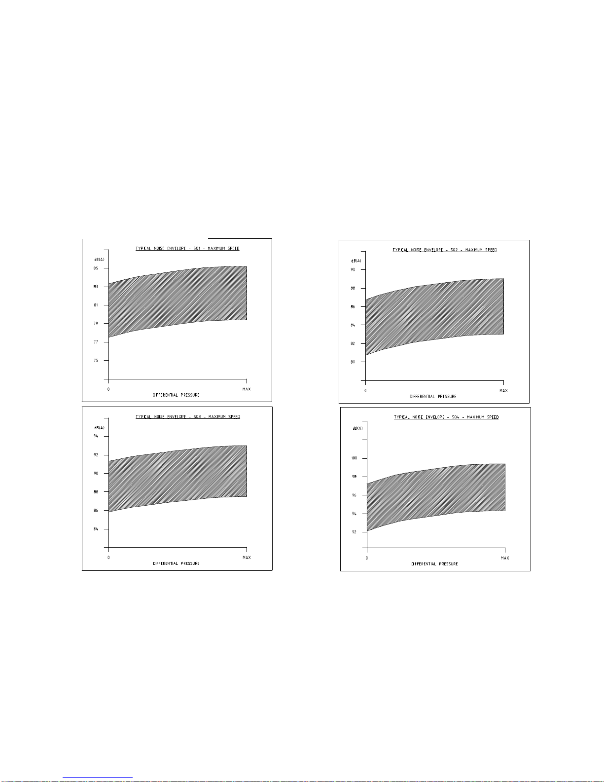
Page 73
5.8 Typical Noise Emission Data
Page 74

Page 74
5.9 Service History.
Pump Serial No:
Date Comments
Page 75

Page 75
5.10 Tool List
Listed below are tools required for the maintenance of the Concept SQ pump range.
TYPE SIZE OR RANGE SQ1 SQ2 SQ3 SQ4
COMBINATION WRENCH 10mm
COMBINATION WRENCH 13mm
COMBINATION WRENCH 17mm
COMBINATION WRENCH 18mm
COMBINATION WRENCH 19mm
COMBINATION WRENCH 24mm
COMBINATION WRENCH 32mm
COMBINATION WRENCH 55mm
HEXAGON (ALLEN) KEY 1/4"
HEXAGON (ALLEN) KEY 3/8"
HEXAGON (ALLEN) KEY 3mm
HEXAGON (ALLEN) KEY 4mm
HEXAGON (ALLEN) KEY 5mm
HEXAGON (ALLEN) KEY 6mm
HEXAGON (ALLEN) KEY 8mm
HEXAGON (ALLEN) KEY 10mm
HEXAGON (ALLEN) KEY 14mm
HEXAGON (ALLEN) KEY
SOCKET DRIVEN
3mm
HEXAGON (ALLEN) KEY
SOCKET DRIVEN
4mm
HEXAGON (ALLEN) KEY
SOCKET DRIVEN
5mm
HEXAGON (ALLEN) KEY
SOCKET DRIVEN
6mm
HEXAGON (ALLEN) KEY
SOCKET DRIVEN
8mm
HEXAGON (ALLEN) KEY
SOCKET DRIVEN
10mm
HEXAGON (ALLEN) KEY
SOCKET DRIVEN
14mm
TORQUE WRENCH ADJUSTABLE UP TO MINIMUM 39 NM (28.765 FT-LB)
TORQUE WRENCH ADJUSTABLE UP TO MINIMUM 77 NM (56.792 FT-LB)
TORQUE WRENCH ADJUSTABLE UP TO MINIMUM 135 NM (99.571 FT-LB)
TORQUE WRENCH ADJUSTABLE UP TO MINIMUM 180 NM (132.761 FT-LB)
DEPTH MICROMETER 0 - 25 mm (0 – 1”)
FEELER GAUGE SET
ROLLING TORQUE METER
0 - 5 NM (0 - 3.688 FT-LB)
ROLLING TORQUE METER
0 - 10 NM (0 - 7.376 FT-LB)
SEAL FACE TOOL SUPPLIED WITH PUMP
HOOK WRENCH TO SUIT LOCKNUT OUTSIDE DIAMETER 32mm
HOOK WRENCH TO SUIT LOCKNUT OUTSIDE DIAMETER 52mm
HOOK WRENCH TO SUIT LOCKNUT OUTSIDE DIAMETER 65mm
HOOK WRENCH TO SUIT LOCKNUT OUTSIDE DIAMETER 85mm
SOFT-FACED MALLET
PIN PUNCH SMALL
STEEL HAMMER SMALL
COMBINATION PLIERS
PRY BAR SMALL
Page 76

Page 76
5.11 Notes
The information contained in this document is correct at time of print, but may
be subject to change without prior notice.
Page 77

Page 77
Wright Flow Technologies Ltd.
Edison Road, Eastbourne,
East Sussex, BN23 6PT
United Kingdom
Phone: +44 1323 509211
Fax: +44 1323 507306
E-mail: [email protected]
Wright Flow Technologies, Inc.
406 State Street
Cedar Falls, Iowa 50613 U.S.A.
Phone: (319) 268-8013
Fax: (803) 216-7686
E-mail: [email protected]
www.wrightflowtechnologies.com
Issue E – 20/01/2015
 Loading...