

WRIGHT BROTHERS GAMBLER AG Instruction Manual
13 Furber Drive
Lee, NH 03824
603-659-9688
http://www.wrightbrothersrc.com
Rev: 08/08/2007

2
Thank you for purchasing The Gambler-AG Discus -launch Glider kit. This kit is designed to be eas y to
build and easy to fly. It also is designed to be able to be discus-launched while still being constructed
mostly of built-up balsa construction that provides an affordable entry point into this exciting and
growing hobby. I hope you enjoy your Gambler-AG as much as I have enjoyed designing and flying it
myself.
Allan Wright Jr.
Wright Brothers R/C
aew@wrightbrothersrc.com
Table of Contents
Specifications..……………………………………………………..………….………………….…….…2
Kit Contents..................……………………………………..…………………………………………….2
Required Materials………………………………..…………………………………………….....….…...2
Suggested Electronics………………………..……………………………………………………………2
General Assembly Information………..…………………………………………………………………..3
Assembly Instructions……………………………………………………………………………….….3-9
Flying Instructions……………………………………………………………………………….…...10-11
Specifications
Wingspan: 48”/1.25 Meter Wing Area: 256 sq. in. Wing Loading: ~3.7 oz/sq. ft.
Chord: 6” At Center Weight: 6.3-6.9 oz Channels: 2
Kit Contents
1 – full-sized plan
1 – instruction manual
3 – 1/16” balsa sheets with laser cut parts
2 – 3/16” balsa sheet with laser cut parts
1 – 1/8” lite-ply sheet with laser cut parts
2 – 1/64” lite-ply laser cut parts
2 – 1/32”x19”x2” balsa sheets
4 – 1/32”x17”x2” balsa sheets
1 – 1/32”x4”x2” balsa sheet
3 – 1/8”x18” hardwood dowel LE stock
2 – 1/16”x2-1/8x3” balsa sheeting
1 – ¼”x1/2”x2-1/4” balsa stick
2 – 2-1/4”x1/8” CF rods
1 – 4-40 nylon bolt and 4-40 blind nut
1 – carbon fiber boom
1 – 6”x15-1/2” 2 oz. fiberglass cloth
1 – 4”x4” Kevlar cloth
2 – 1/32”x27” piano wire pushrods
1 – pkg. Du-Bro Mini E/Z connectors
2 – Du-Bro Micro E/Z Link pushrod connectors
2 – Du-Bro Micro control horns
1 – 1”x50” carbon fiber ribbon in 1/8” segments
2 – 10” pieces of Kevlar thread
Required Materials
1 – Roll of lightweight covering material. (Recommended Oracover Light or So-Lite/Nelson Litefilm)
Thin C/A and Medium or Thick C/A glue
Epoxy finishing resin, preferably 30-minute on longer cure
3-M Super 77 spray adhesive, or similar
Clear packing tape
Suggested Electronics
Berg Microstamp (single conversion) or FMA M5 or HiTech Electron 6 (dual conversion)
Two micro-servos. Hitec HS-50 highly recommended. Similar may be used (GWS Pico, Cirrus CS-10).
Receiver battery. Can be 3x50mAh Nicad or 4x110 or 280 mAh NiMh or 1x4.2V Lithium Ion. Lithium
Polymer packs are not recommended as they are too light to properly balance the model.
Gambler-AG Kit

3
General Assembly Information
Please thoroughly read these instructions carefully before starting construction. Those who have built
balsa models before will find the construction sequence quite straightforward. For those who have not, I
hope to have provided sufficient detail at each step to make the instructions clear. If you have any
questions, e-mail info@wrightbrothersrc.com for assistance. A PDF version of this manual is available
on our website which you can print out on your printer with color illustrations.
This kit contains laser-cut parts that may have light charring on the cut surfaces. If you use Ambroid or
aliphatic resin glues, you may want to lightly sand the edges of these parts with 220-grit sandpaper to
allow for better glue bonding. I recommend thin CA (cyanoacrylate a.k.a. ‘super glue’) for assembly of
this kit. It speeds assembly and does not require additional sanding of the laser-cut parts. Except where
indicated, parts can be first held together, then thin CA can be “wicked” into the joints. The laser-cut
parts are held onto the balsa sheets by small, uncut spots o n each part. Remove the parts from the sheet
by carefully cutting these spots with a sharp hobby knife as the parts are needed.
Besides the required materials listed above, you should have the following building supplies: 220-grit
sandpaper; a hobby knife ; small clamps; straight edge, ruler and right-angle gauges; and a flat work
surface with reference lines on it.
Skilled builders should be able to assemble this kit in three to four evening building sessions. Beginners
should allow four to five evening sessions to comfortably assemble this kit. Both will take an additional
evening to cover the wing and pod with covering. Take your time and enjoy the experience!
Carbon Fiber Ribbon Information
The carbon fiber ribbon provided in this kit is 50” long and approximately 1” wide. You will note that it
is made up of eight (8) 1/8” smaller segments held together with a thermo-plastic cross stitching. In
order to be used to build this kit, this ribbon must be carefully separated into four (4) separate ribbons
each containing two (2) of the 1/8” wide segments. It is tempting to quickly run your hobby knife
between the segments to separate them, but this is not the recommended method for separating the
segments as such a technique is VERY LIKELY TO DAMAGE ONE OR MORE SEGMENTS of
the carbon fiber. Instead it is recommended that the segments be carefully separated a small bit at a time,
periodically checking that the hobby knife remains between the segments and doesn’t drift into one. If
you do partially fray one of your four pieces, you may use that one to cut up into the smaller pieces used
on the fuselage and tail surfaces.
In all cases where the carbon fiber ribbon is to be applied to balsa, the best method for doing this is to
lightly spray one side of the ribbon with spray adhesive such as 3-M Super 77 or similar and
immediately apply the adhesive side of the ribbon to the balsa. The spray adhesive is just to temporarily
locate the ribbon and allows for easy repositioning. Once you are happy with the location of the ribbon
and are sure that it is fully adhered to the balsa, saturate the carbon a section at a time with thin CA,
rubbing the saturated section with waxed paper. Be careful to do this in a very well ventilated area, as
the CA will ‘kick’ quickly and aggressively when applied to the carbon fiber and will produce copious
fumes which are quite irritating and can cause allergies over prolonged exposure. Odorless or foam safe
CA can be used for this process, but it is not recommended. Everywhere else in the k it construction
either regular or odorless CA may be used.
In all areas where the carbon fiber ribbon is applied, it will be desirable to sand the ribbon smooth until
the thermo-plastic cross stitching is no longer visible and does not produce any noticeable texture. When
doing this 220-grit sandpaper is recommended. Be sure to always sand in the direction of the carbon
fibers, never sand across the carbon fibers as it will unnecessarily weaken them. The provided carbon is
Gambler-AG Kit
4
thick enough to have a portion of it’s thickness, up to 25%, sanded off in order to get a smooth finish,
without adversely effecting it’s strength.
Assembly Instructions
Step 1: Locate the fuselage pod bottom on the 1/16” laser cut sheet. It is the only part not completely cut
out with t he laser. Carefully cut out the part, making sure to leave at least 1/2” of extra wood outside of
the drawn lines. You will trim this panel to size later. Once you have the part cut out, you may cut/sand
the nose side and tail side (the two shortest sides) flush with the drawn outline, leaving the other sides
oversized.
If you have a building board, cover it with wax paper, and pin the pod bottom onto the board with the
pod centerline aligned with one of your board’s reference lines. If you’re not using a board, draw a
straight line with a long straightedge on the back of the plan, cover that with wax paper and pin down
the pod bottom aligned with the drawn reference line.
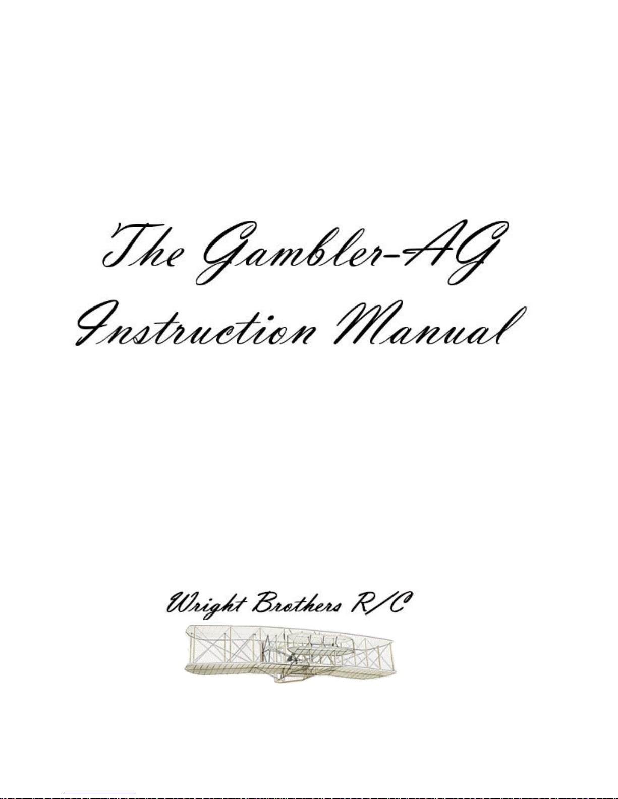
Step 2: If your tail boom doesn’t have a slot cut in one end (scratch builders), cut a slot 1/16” wide into
one end 2-1/16” long. At the end of the slot wrap the boom with Kevlar thread and soak with thin CA.
This will strengthen the boom and prevent it from splitting when launched. Four to six wraps will be
sufficient. The provided Kevlar thread is much longer than you will require. If you wish you may color
the Kevlar thread with permanent black magic marker after it has been glued into place.
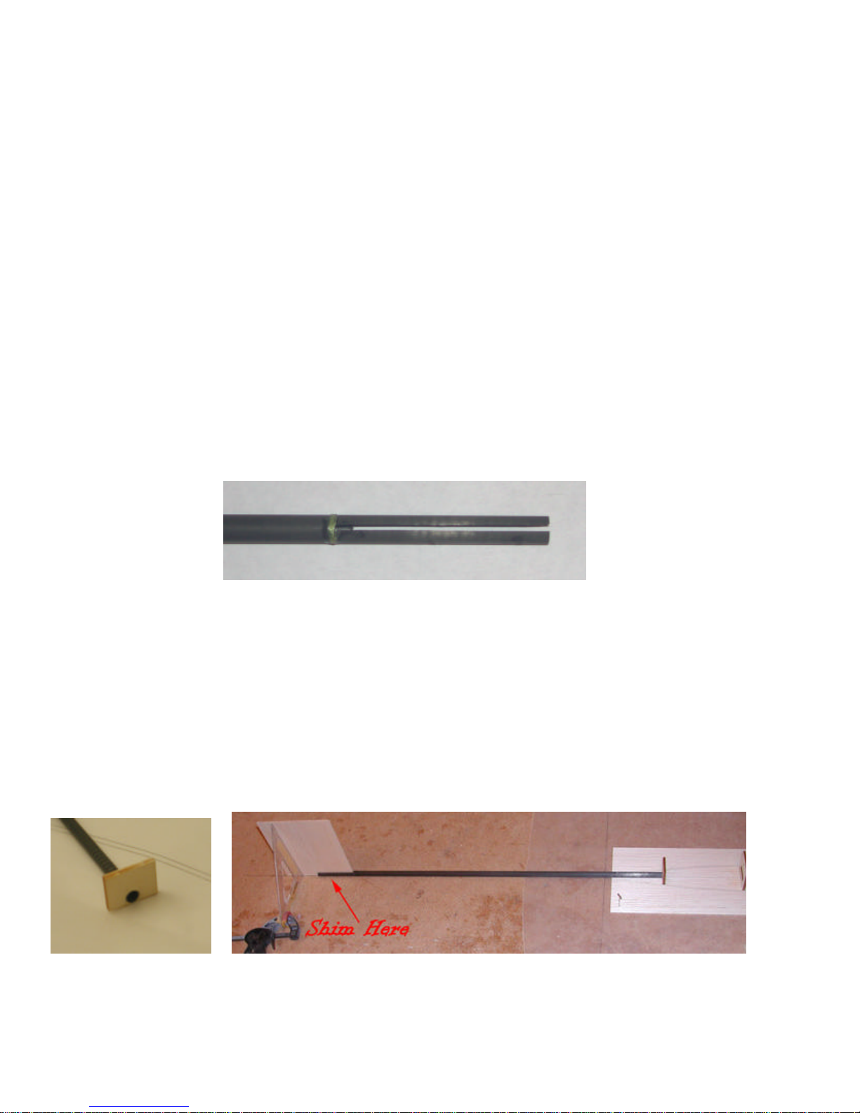
Locate former F3 on the lite-ply part sheet. Remove it and check the fit of the boom to the hole. Insure
that the non-slotted end of the carbon fiber (CF) boom fits snugly and will align with pod bottom when
glued. Enlarge the hole in F3, if necessary. Lightly sand the area of the boom that will be glued with
220-grit sandpaper to allow the glue to bond well. Slide the former onto the boom but do not glue yet.
Using pins, secure the boom to the building board -- making absolutely sure that the tail end of the boom
is aligned with the centerline of the pod and the front end of the boom is located at the front reference
line of F3 as drawn on the pod floor. Shim the tail end of the boom with a scrap of 1/16” balsa to insure
it is level. Using a scrap of balsa temporarily inserted into the slot in the boom, insure that the slot is
perpendicular to the building board. Once you’re sure everything is on the centerline, and F3 is located
over the drawn location on the pod floor, secure the assembly to the pod floor with thin CA.
Step 3: Glue formers F2 and F1 to the pod floor with thin CA where the location lines are drawn. Make
sure that they are at right angles to the pod floor.
Gambler-AG Kit
5
Step 4: Remove the two laser-cut fuselage pod sides from their sheet and glue to the pod bottom as
drawn on the part. Secure the sides to the formers with thin CA. Note: For now, the tail ends of the sides
are glued against the CF boom at the rear of the pod. Since the boom is tapered the sides may not fit
exactly where drawn on the floor part. This is OK.
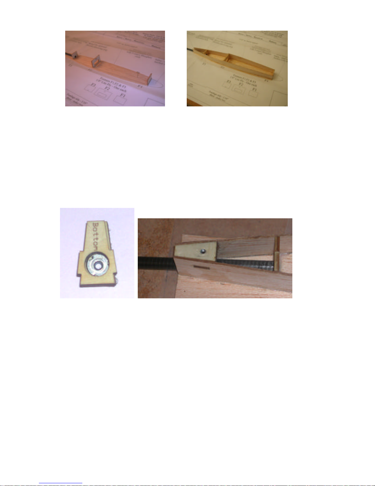
Step 5: Find the three wing hold down pieces on the 1/8” plywood sheet. They are keystone shaped and
marked top, middle and bottom. Press the blind nut into the one marked top. This should be done firmly
so that the prongs in the nut fully penetrate the wood and secure the nut in place. Glue the midd le and
bottom pieces on top of the flat portion of the blind nut to make the assembly shown in the left photo
below.
Step 6: Test fit the assembly created in step 5 into the rear of the two fuselage sides as shown in the
photo to the right above. Once you are happy with the fit glue the assembly with medium CA or wood
glue. There will be a gap at the rear of the fuselage between the hold down block and the boom. This
gap can be filled with scrap and sanded flush. Be careful not to block the area below the blind nut as the
hold down screw will protrude there.
Step 7: You will need to sheet the top of the front of the pod. To balance the plane, one or both of the
servos are located direct ly in front of former F2. To make installation and removal of this servo easier, a
semi-permanent hatch is used. Glue a 1/4” strip of 1/16” sheet (taken from one of the 1/16” sheets
provided) directly over former F2, making sure the extra width protrudes o ver the forward servo area.
Glue in the 3/16”x 3/16” hatch support as indicated on the plans, and glue a 1/4” wide strip of 1/16”
sheet over the support making the extra width protrudes back towards the servo area. Cut a piece of
1/16” sheet to cover the servo opening, and temporarily secure in place with tape.
Gambler-AG Kit
 Loading...