

Wren Turbines 44 TurboProp Installation And Operating Manual
W
W
W
I
N
S
T
I
N
S
T
I
N
S
T
R
R
R
A
L
A
L
A
L
L
L
L
E
E
E
A
T
A
T
A
T
N
N
N
I
O
I
O
I
O
N
N
N
4
4
T
U
R
B
O
P
R
O
P
4
4
T
U
R
B
O
P
R
4
4
T
U
R
B
O
P
A
N
D
O
P
E
R
A
T
I
N
G
M
A
N
U
A
L
A
N
D
O
P
E
R
A
T
I
N
G
M
A
A
N
D
O
P
E
R
A
T
I
N
G
N
M
A
N
September 2008
U
A
L
U
A
L
Copyright Wren Turbines Ltd
R
O
O
P
P

WREN 44 TurboProp Manual
Congratulations on your purchase of the new miniature Wren 44 TurboProp gas turbine engine.
This manual has been prepared to help you set up and safely operate your engine. If you encounter any
problems then please consult this list first and if you cannot find a solution please get in touch with us. The
engine is simple to prepare and use but certain precautions must be observed for your safety and others
near you – see safety notes.
Included in the manual is a problem checklist to help solve any problems you may encounter in operation.
Please remember, although small and seemingly harmless the engine is definitely not a toy and must be
treated with utmost care and consideration to your own safety and others around you. The manual also
contains sections on the individual components of the installation and operation, refer to these for more
detailed information.
Contents:
3 Introduction
4 Package contents
5 Weights and Measures
6 General description of the two-shaft drive system
9 Detail description of the turboprop unit and ancilliaries
13 Safety issues, do's and don’ts
14 Warranty, service and repair
15 Performance
16 Propeller selection and balancing
17 Fuel consumption/duration
20 Installation Do’s and Don’ts
22 Wiring and Plumbing Schematic
35 Installing the system components
23 Connecting the system components
27 Setting up the ECU
28 ECU Failsafe function
29 Preparing for running
31 Running the unit
36 Starting and running, problem checklist
34 Flying the unit
35 After running
37 Storage
38
Front Cover Pictures - Acknowledgments:
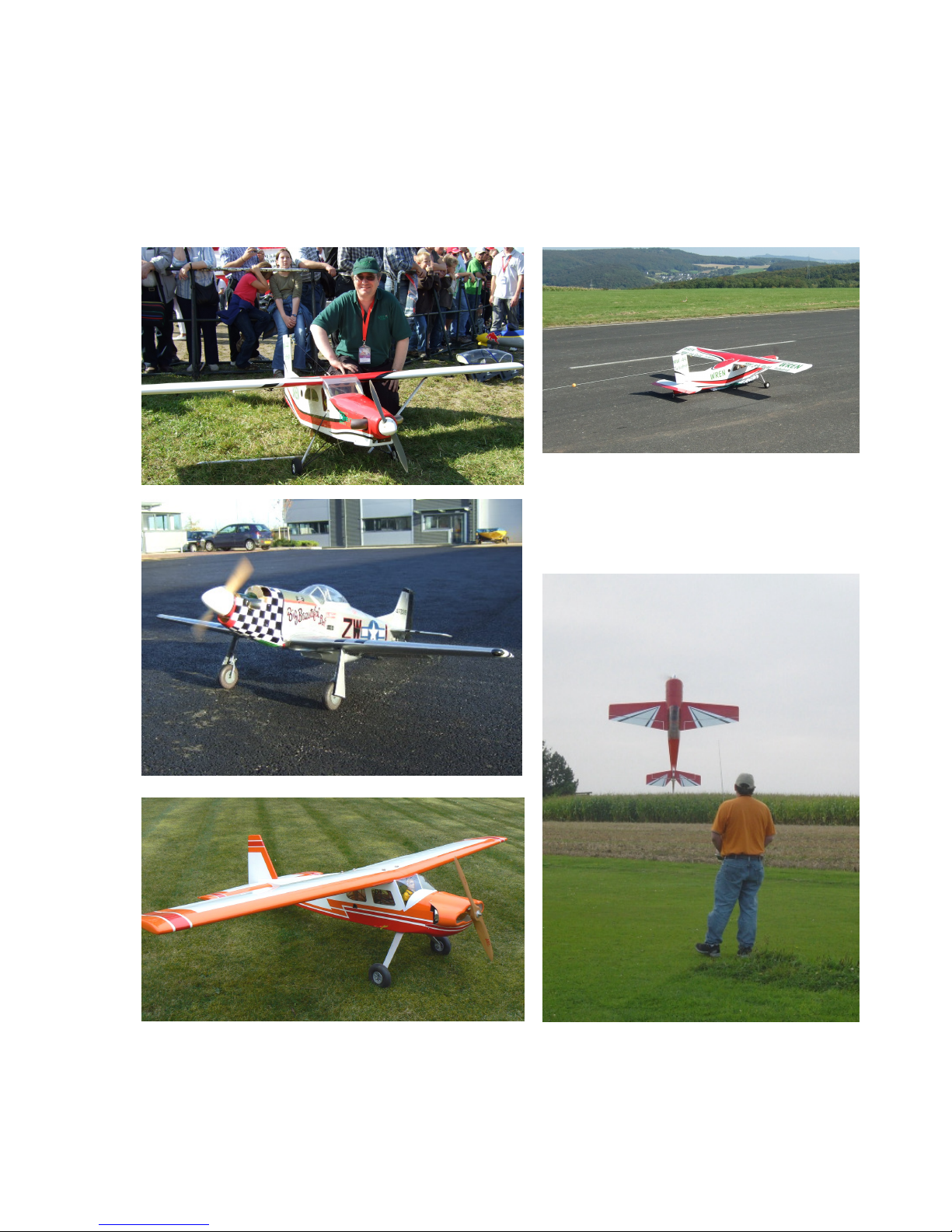
Front page upper – the first 44 Turbo-Prop prototype installed in a Pilatus “Porter” for gliding towing, by kind
permission from Lucien Gerard, Luxemburg.
Front page middle - the 2nd prototype Wren 44 Turbo-Prop installed in a Top Flight “P51 Mustang”, by kind
permission from Lucien Gerard of Luxemburg.
Front page lower left – the first production Wren 44 Turbo-Prop installed in a Graupner “Taxi”. By kind
permission from owner, Barrie King.
Front Page, lower right – Wren 44 Turbo-Prop installed in a YAK88 from ExtremeFlightRC, flown by Jeannot
Behm.
Basic servicing
Wren Turbines Ltd. Unit 19, Century Park Network Centre, Manvers, Rotherham,
South Yorkshire. England.
Tel. 01709 877439. Fax 01709 875935 Email: info@wrenturbines.co.uk
Wren 44 TurboProp Users Manual. Copyright Wren Turbines Ltd February 2008 Page 2

The new Wren 44 TurboProp
Introduction
This new development from the highly popular Wren 44 Gold thrust engine stable, has been long awaited. It
has built on the success of the Wren 54 Turboprop which has now been on sale in various forms since 2002.
The engine has been the outcome of a long R&D programme primarily concerned with maximising the
performance and minimising the aggravation of installing and operating, allowing the flier to get on with the
business of flying.
We have been careful to keep the weight of the unit down but have not compromised stiffness which has
shown itself to be a major concern for turbo-props. The engine is not modified for use in this application
apart from a small hole drilled in the case to add a lubrication port, enabling the full perfomance to be used
in driving the propeller, producing performance usually described as “awesome” by all those witnessing it.
The gearbox assembly is strongly built to withstand many hours of operation and is designed to be
lubricated with a small fuel take-off from the engine. All this is automatic and the user need do no more than
put fuel into the tank, charge batteries and go fly!
We have tried hard to produce a compact high power to weight engine capable of filling the gap left by the
noisy medium to large I/C engine, and the existing range of turbo-prop engines now becoming available.
Most of these are really only suited to large aircraft around 2.5 to 3m (8’ to 10’) wingspan, which has
implications for cost, transport and suitability of flying field. There are a large number of airframes already
available in the 2m (6’) size that are attractive for conversion to turbo-prop for the reasons outlined above
and are suited for the average club flier. The low installed weight around 2kg compares well with equivelent
2-cycle engines and helps to keep the wing loading sensible.
Noise is becoming a major concern and the 44 turbo-prop enjoys a remarkably low noise figure, rivalling
electric models in many cases. The noise is predominantly propeller noise and with the smooth application
of torque and total absence of power pulses enables a very low perceived noise level to be achieved.
The Wren 44 Turboprop enjoys the same highly responsive engine as the Wren 44 Gold thrust version so
the absolute minimum throttle lag can be appreciated by those keen on prop hanging and the usual
aerobatics. The small engine size enables the fuel consumption to be described as “stingy” so no need for
lugging a big fuel bottle around.
Importantly, the engine is already well established so you are not buying an unproven design. Parts and
service is readily available and the hundreds of Wren 44 Gold customers across the world will testify to the
longevity and ease of use of this world-beating engine.
Above all - Enjoy!
From all the team at Wren Turbines Ltd
February 2008
Special thanks to:
Lucien Gerard, a good friend and colleague of all at Wren
Turbines, who was the first customer to build a Wren 54
turboprop back in 2002 that still flies in an Embrear Tucano
and encouraged this development from the start.
Lucien supplied aircraft for flight testing the 1st and 2nd Wren
44 turbo-prop prototypes and undertook all the test flying. His
generous help and feedback has greatly assisted and
encouraged us to push this unique development forward into
successful production.
Thank-you.
Wren 44 TurboProp Users Manual. Copyright Wren Turbines Ltd February 2008 Page 3
The Wren 44 TurboProp package contains the following:
1) Wren 44 TurboProp Engine
2) Fuel pump
3) Autostart ECU (Engine Control Unit)
4) ECU data display terminal
5) ECU Battery (2-cell LiPo)
6) Propane canister valve
7) Fuel solenoid
8) Propane solenoid (with attached adjustable flow control valve)
9) Propane tank and one way valve
10) Brass two-part quick-release propane connector
Lay out the engine and its support equipment on a clean surface and identify all the components.
Weights and Measures
Weights:
Power unit complete with cables 1710g (3-3/4 lbs)
Fuel pump 88g (3oz)
Valves (Propane and Fuel) 65g (2-1/4oz)
ECU (Engine Control Unit) 35g (1-1/4oz)
LiPo battery 7.4v, 1500mAh 80g (2-3/4oz)
All up weight 1978g (4lb 5-3/4oz)
Wren 44 TurboProp Users Manual. Copyright Wren Turbines Ltd February 2008 Page 4
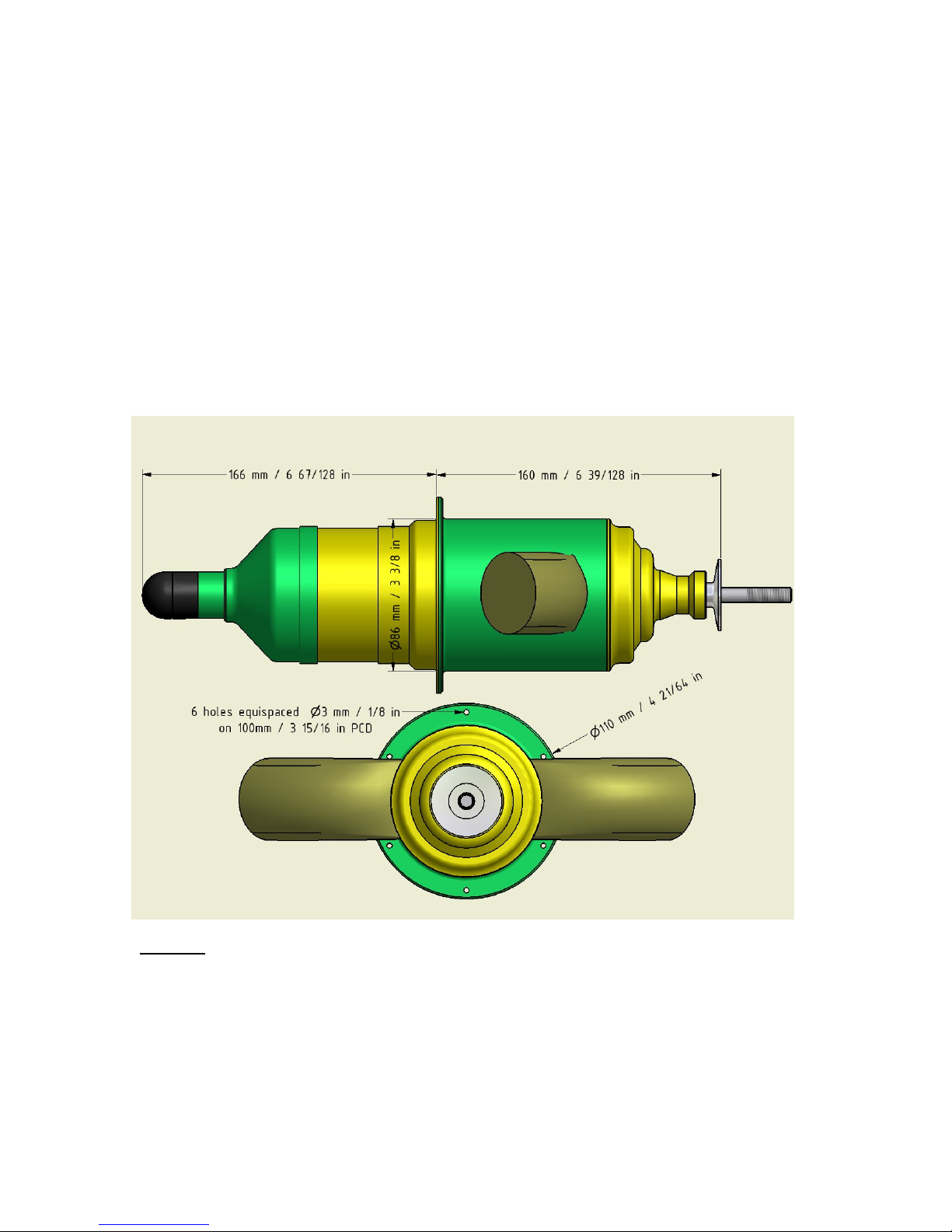
Measurements:
nd
Overall engine length 365mm (14-3/8”)
Overall width across standard exhausts 245mm (9-1/2”)
Engine mounting flange to prop driver 160mm (6-5/16”)
Mounting flange diameter 110mm ( 4-5/16”)
Mounting bolt circle 100mm (3-15/16”)
Mounting bolt M3 (or 4-40 UNC), 6-off, length to suit
Propshaft thread M8 x 1mm pitch
Propshaft length 40mm (1-1/2”)
Max propeller thickness 30mm (1-3/16”)
Prop driver diameter 40mm (1-1/2”)
Prop nut size 12mm A/F
Glowplug JP PowerPlug type F
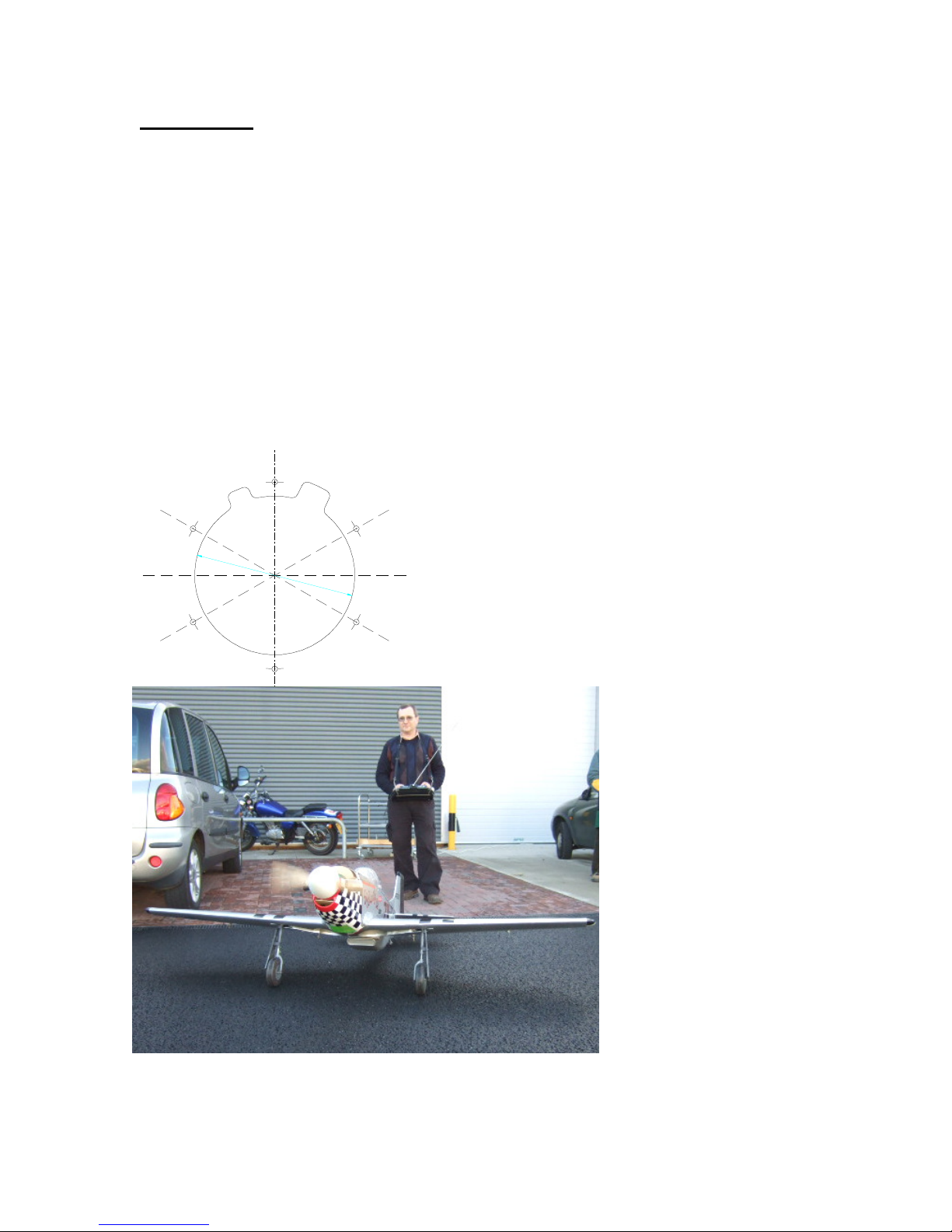
A couple of templates for making the cutout for the engine mounting are included at the rear of
the manual, to full scale. Simply cut out, stick to the front of the firewall and cut through.
TOP
GlowPlug
The template looks like this (reduced version for show
only):
6 off, Ø3
(1/8")
Viewed from
Propeller end
Ø
8
5
An determined look on the face of Lucien Gerard as he taxis out the 2
prototype turboprop in the Top Flight “P51 Mustang” for handling
checks, ouside Wren Turbines HQ. Nov 2007
Wren 44 TurboProp Users Manual. Copyright Wren Turbines Ltd February 2008 Page 5

General description of the Wren 44 two-shaft drive system
The Wren 44 TurboProp is the worlds smallest commercial 2-shaft turbo-prop engine. It is
designed for use in miniature aircraft applications in place of an I/C engine. It is generally suited
to aircraft up to 25kg (55lb) in all up weight and will replace I/C engines of around 80cc (4.8cu
inch). The engine runs on standard kerosene and is supplied in full auto-start configuration.
What is a two-shaft system?
The two shaft system means there are two independant shafts running within the unit. The first
shaft is contained within the engine end of the unit and rotates at very high speed (up to
195,000rpm) with just a small compressor wheel and turbine attached at each end. This engine
end of the unit generates a flow of gas at high pressure and volume, and its operation is exactly
as a small gas turbine engine. It fulfills the function of what we call a gas generator. If a nozzle is
attached to the outlet of the engine it imparts a slight squeezing of the gas into a high velocity jet
for producing jet thrust and is the configuration for a thrust engine. For a gas generator version of
the engine, instead of squeezing the gas through a nozzle it is redirected by a vane assembly to
turn a 2nd turbine wheel mounted on the 2nd stage shaft. This is driven round in the gas stream
and this rotation drives the input shaft to the gearbox and onwards to the propeller. This 2nd
turbine is much larger in diameter than the 1st stage and correspondingly runs much slower - up
to only 90,000rpm - still far higher than any 2-stroke or electric motor could achieve, but at a high
torque level. The energy given up by the gas driving the 2nd stage turbine drastically reduces the
speed of the exhaust gas with the result than only a small residual thrust remains from the
exhaust outlets.
What happens if I stall the propeller?
When operating from long grass or in a nose-over situation that causes the propeller to stall, the
gas generator will continue to function normally with little ill-effects. On releasing the propeller
from its stalled form it will spin back up to it's normal running speed. This should be born in mind
when retrieving the model from the long grass or nose-over situation - for you or your helper to
keep well clear of the propeller whenever the gas generator is running.
What sort of gearbox is required?
The modest rpm levels generated by the 2nd stage turbine (by gas turbine standards) enable an
suitable reduction to be contained in a small gearbox, the ratio of which is chosen to suit the
operational needs of the load driven. In the case of the 44 TurboProp the reduction is 9:1 and this
gives a propeller shaft speed range of 6,000-9,000rpm. The 2nd turbine has a wide operating rpm
range and may be slowed with high load or allowed to speed up with low load without upsetting
the 1st stage, therefore the choice of propeller is not at all critical, providing it presents enough
load for the system (see warning below). The main criteria for propeller choice being the type of
plane the unit is fitted to (scale, aerobatic, sports etc).
What are other two shaft examples?
Other Wren applications that use the same 2-shaft system are the Wren 44 Marine variant that
has a 2.3:1 reduction gearbox for an output speed of 25,000-40,000rpm and the Wren 44 Heli
unit with a reduction of 4:1 and output speed range of 12,000-20,000rpm.
WARNING - it is most important that there must always be some load on the output shaft
as otherwise the 2nd stage turbine will be running unrestrained and may easily speed up
beyond it's safe running speed, even when the gas generator is running at only a modest
rpm. This means the unit should never be run without a suitable propeller fitted.
Wren 44 TurboProp Users Manual. Copyright Wren Turbines Ltd February 2008 Page 6

What is the effect of airspeed on the engine?
Once the aircraft is in the air the propeller rpm will increase as its load reduces with forward
speed. An rpm increase of 10-15% can be expected in the air so always choose a propellor that
keeps the output speed below 9,000rpm. It is this increase in propeller rpm in the air which gives
the turbo-prop powered aircraft a high airspeed capability and shows a definite edge over it's I/C
engine counterpart. I/C engines have a more limited unloaded speed capability, as it can result in
the engine mixture strength "leaning out" which can cause engine damage. By contrast the turboprop will enjoy running cooler as the propeller speed unloads leading to longer life and reduced
loading on critical components.
How is it mounted?
The unit is housed within a purpose made containment system which encloses the hot section
components in a three-section aluminium jacket enabling the installation to be limited to a simple
firewall mounting and six bolts and nuts. This firewall provides the essential air separation for gas
generator intake air and the warm air generated by the exhaust unit by placing a solid partition
between them. In normal running the casing will only reach about 100-130'C minimising the
chances of heat damage to the aircraft fuselage. No further stiffening is required or advised for
the unit, this approach enabling the conversion from I/C engine to turbo-prop power to be
accomplished with ease. The mounting supports the engine and gearbox at the approximate
centre of gravity and is built to withstand all normal loads such as might be subjected to the
equivalent I/C engine.
Aren't gas turbine more dangerous than I/C engines?
No. In the unfortunate event of a sudden arrival (or crash) the mounting helps to maintain
containment of all the hot section parts from heat sensitive parts of the airframe and accessories.
Turbine fuel has a high flashpoint which means at normal ambient temperatures it is extremely
difficult to ignite, unlike gasoline or glow fuel which is a low vapour temperature and ignites easily.
With no exposed high temperature components the risk of accidental combustion is greatly
reduced. As starting is undertaken with the operator and observers behind the propeller there is
no possiblility of a sudden power surge allowing the aircraft and propeller to run forward to the
operator such as can happen with I/C engines, with disastrous consequences for fingers and
limbs. The 2nd stage fully encloses the outlet of the gas turbine section affording a high degree of
protection against any component failure due to accidental damage or persistent operation
beyond the normal operational duty cycle.
What's it like to operate?
The power unit itself is operated as a normal miniature gas turbine and possesses all the
standard features of automatic push-button starting and cooling, totally vibration free operation,
very quiet running and exceptional power to weight ratio. The throttle response is of the best in its
class - the small gas generator rotor is small and light allowing very quick spooling to be achieved
safely. Being a very small gas turbine it's fuel consumption has been described as "stingy" - a
typical 10minute flight being easily achieved with a single 1ltr fuel tank, depending on the flying
style. Those fliers used to a 3ltr fuel tank for equivelent flights should find this aspect of operation
a welcome relief.
How does it compare to I/C power?
The exceptional power to weight ratio which is close in performance levels to an 80cc gasoline
engine but weighing in at only 1.71kg (3-3/4 lbs) allows the operator a level of dial-in performance
previously enjoyed by only those operating high performance specialist engines with tuned pipes
etc, with all the attendant noise, extreme vibration and operational issues associated with such
equipement. Scale fliers will really enjoy the smooth and quiet response and operation coupled
with high power reserve to get out of those difficult situations that scale aircraft with fully
articulated surfaces, flaps and fine surface detail, can find themselves in. The high torque ability
of the engine allows it to cope well with a wide range of prop sizes and shapes which will enable
those scale three and four blade props to be a practical reality and further add scale effect.
Almost all aircraft will enjoy an installed power to weight ratio exceeding 1:1 - in many cases
Wren 44 TurboProp Users Manual. Copyright Wren Turbines Ltd February 2008 Page 7

exceeding 2:1! With a static thrust exceeding 16kg (35lb) the unit should be quite adequate in
power to enable an acceptable flight performance in a plane of 25kg (60lb) or more.
What about flying in noise sensitive areas?
Fliers with noise sensitive flying fields will enjoy the almost silent operation of the unit comparable
to electric flying. Such users are encouraged to make good use of the current crop of quiet
propellors and resist the temptation to zoom around the field like a pylon racer! Sports fliers can
make full use of the highly tractable response and enjoy quelling the myth that turbo-props cannot
prop-hang.
What about smoke?
The engine itself is a clean burning gas turbine that does not produce any smoke in normal
operation. However the gearbox bearings are lubricated with a very small amount of fuel which at
low rpms or throttling down can sometimes be seen as a small puff of smoke, but this is normal.
The minimal oil percentage used in the fuel helps to minimize pollution from unburnt fuel,
although operation of the gas turbine does produce an very distinguishable smell which for many
is the "raison detre" of this type of model flying.
What propellers do you recommend?
An important question. In all cases, we recommend only wooden props as in the even of a nose-
over in a taildragger aircraft, the prop will break and not damage the engine. Similarly, in the
event of an undercarriage failure where the u/c will not extend and a belly landing is required, a
prop strike is inevitable and a strong carbon prop will not bend enough to protect the engine and
can cause serious damage to the propshaft. Wooden props are available in sufficient styles and
shapes to cover most needs although users should satisfy themselves in the case of three or
more blade props, that the hub fixing is adequate enough for the power of this engine.
Wren 44 TurboProp Users Manual. Copyright Wren Turbines Ltd February 2008 Page 8
Detail description of the Wren 44 two-shaft drive system
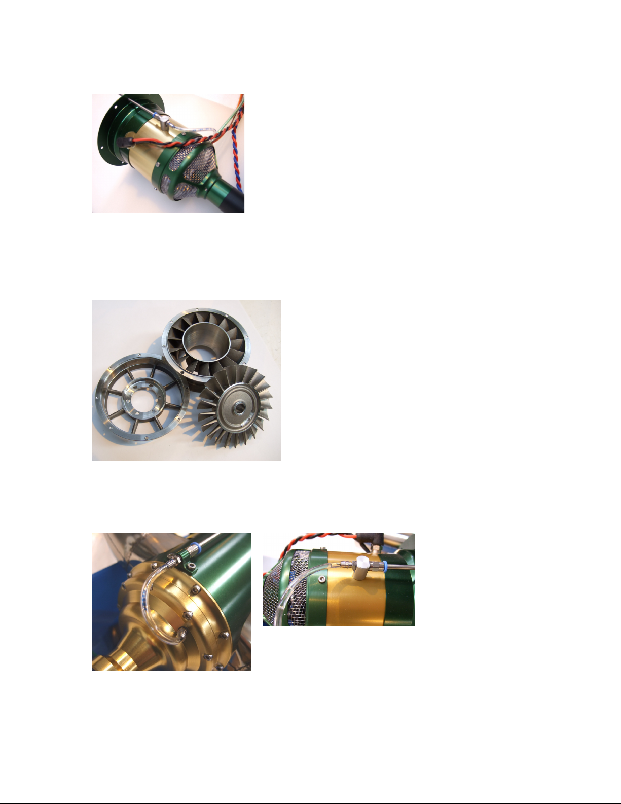
Gas Generator
The gas generator used in the system is the well proven
Wren 44 GOLD engine which has the standard Wren FOD
guard fitted – this is no place for a tea strainer. A lubrication
port in the outer casing has been added and this connects
through a stainless tube to the gearbox. Other than the lube
outlet there are no other changes to the engine and the full
throughput has been utilised to generate shaft power.
This TurboProp engine has been fully run and tested
It is important to stress the unit has been fully tested with all the components supplied with it
before it left the factory at Wren Turbines Ltd. There should be no need to make adjustments
other than setting the radio to the ecu. Please refrain from jumping in and changing things just
because you or a friend have another Wren 44. The settings match the components used and
may not be the same as you are used to.
Hot Section
A specially designed and manufactured miniature
interstage and guide vane assembly, cast from high
temperature stainless steel is bolted to the engine.
A purpose made 66mm power turbine – not just
taken from a thrust engine, is cast in Inconel 713c
and is fitted and running on a fully hardened and
ground shaft in a pair of preloaded high speed
ceramic angular contact bearings. The shaft tunnel
they run in is made from low expansion stainless
steel.
These components define what is called the hot
section. Nothing has been left to chance.
Gearbox
The front of the turbine shaft is contoured with a hardened and ground gear profile and supplies
the shaft power into a specially design high speed planetary gearbox. This heavy duty assembly
utilising fully ballraced support shafts and the planet carrier has been ground and bored as an
assembly to retain great strength and accuracy.
The housings are
anodised to resist
corrosion and maintain
their lustre. The gears
are fully hardened and
are able to run with
long life using just a
small amount of engine
fuel bled off the gas generator fuel system. To keep the flow
to a low level the oil percentage is maintained at 5% to
ensure satisfactory lubrication.
The lubrication reaches the gearbox by a small pipe in the gearbox front wall and is fed from a
special fitting mounted on the engine. The gearbox is designed to retain much of the lubrication
and only release what is surplus via the power turbine bearing.
Wren 44 TurboProp Users Manual. Copyright Wren Turbines Ltd February 2008 Page 9
The Mounting
The gearbox housing incorporates a Wren Turbines’ innovation – a fully integral mounting
system. This specially designed housing answers two of the criticisms of turbo-props – that of
their generally awkward mounting arrangement for gearbox and engine, and the amount of heat
they generate within the airframe.
Our unique new system is machined from solid aircraft
grade aluminium and carefully anodised to retain its
corrosion resistant qualities and durability of finish. It
provides a secure and rigid connection between the
firewall and gearbox and provides full support to the gas
generator at its C of G. This eliminates the danger of
distorting the hot section between the engine and
gearbox when individually clamping engine and
gearbox to different sections of the airframe. The Wren
system also allows a very simple mounting for the
engine – just align the supplied template (at the back of
this manual), and cut out the shape, drill the six mount
holes and bolt onto a firewall like a 2-cycle engine. This
also allows for the simple offsetting of the thrust line by
simply building it into the firewall at the point of construction, as recommended or included for the
I/C installation.
The mounting has a further advantage – it envelopes the hot section and exhaust sections and
holds in the heat which would normally be released to the interior of the aircraft. Such heat
release can cause heat damage to paint finishes cowl materials, or make it difficult for the engine
to get an adequate supply of essential cool air for the engine to run on. We think the system is so
good that some day all turbo-props will look like this.
Ancillaries
ECU (Engine Control Unit)
Data display terminal
RPM pickup (mounted in engine)
Temperature Probe (mounted on engine)
Fuel pump
Propane valve and flow restrictor
Fuel valve
Ecu battery
Propane tank
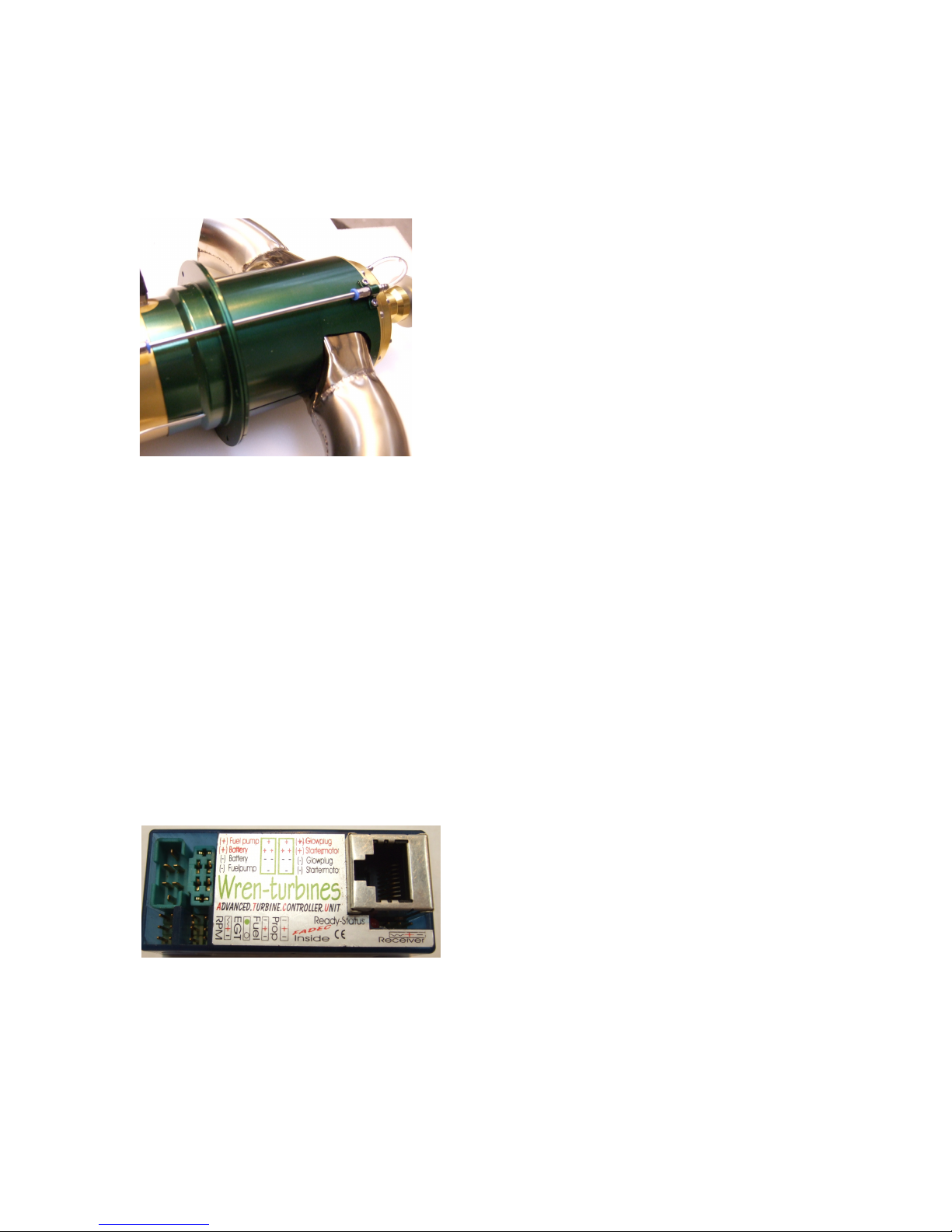
ECU (Engine Control Unit)
The ECU and ancillaries are identical to the thrust engine
variant and use similar programmed settings. It is
important however, that users do not change settings
from those set without refering back to Wren Turbines.
The ECU is the well proven Digitech type supplied by
Gaspar Espiell and which the engine, fuel pump and ecu
battery plugs into. It controls the engine through its
starting, running and cooling down phases. A signal lead from your receiver connects to the ecu and
provides the throttle commands to the engine from the receiver throttle channel and next to it is the larger
socket for plugging in the Data terminal (see below). The ECU unit has a printed label which shows where all
the engine accessories are plugged in; “RPM” - rpm pickup (the servo-type lead coming out of the cowl of
the engine), “EGT” - temp’ probe, “Fuel” - fuel valve, “Prop” - propane valve. To orientate these servo-type
leads, the “-“ refers to the brown wire. There are various timers that are used to keep track of running hours
– see the detail section on setting the ecu.
Wren 44 TurboProp Users Manual. Copyright Wren Turbines Ltd February 2008 Page 10
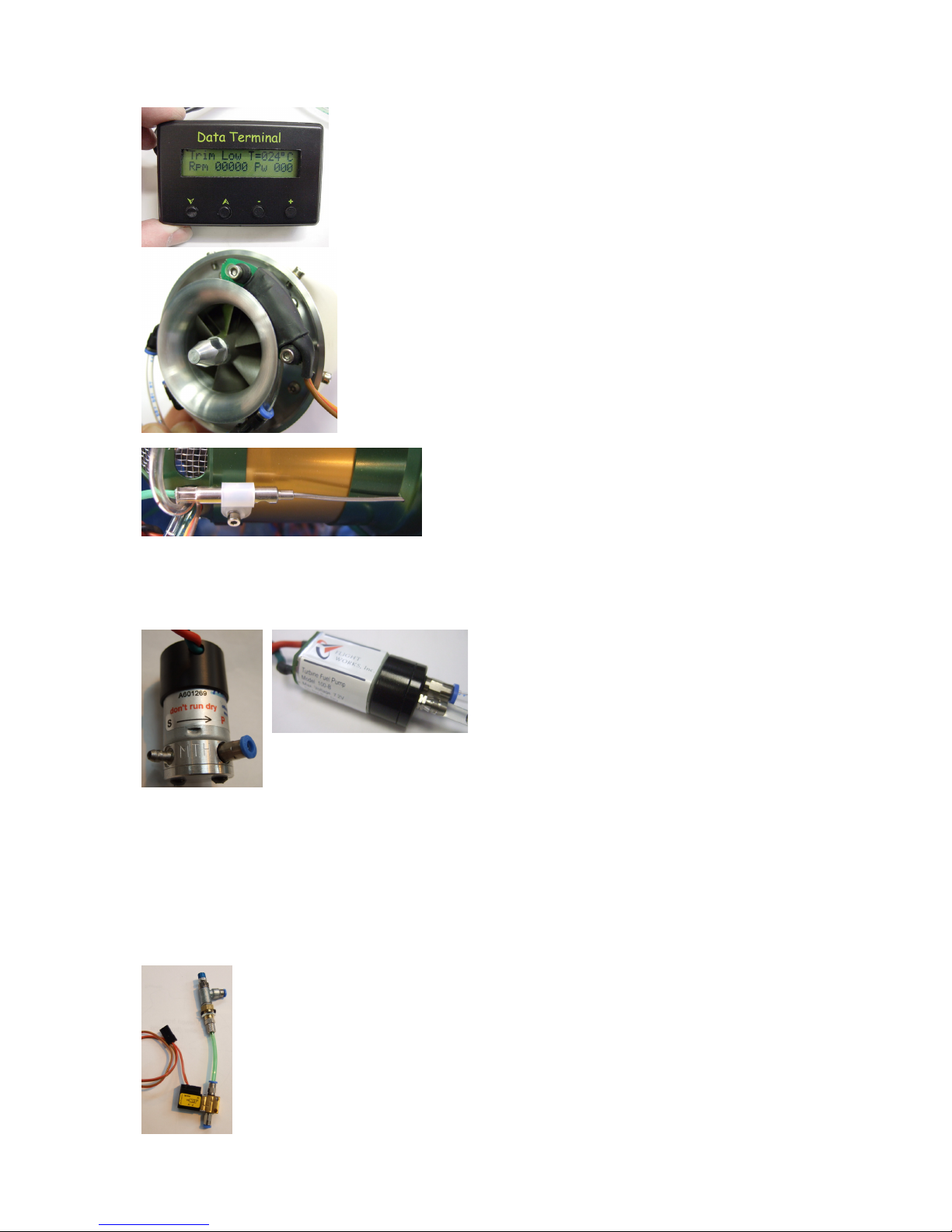
Data Terminal
The ecu is accessed from the outside world by a port with a telephone style
socket connector and a hand-held unit called the Data Terminal.
This terminal is primarily a display for the engine but is also used to input
settings from buttons on its front panel. The terminal’s functions are
described in more detail later.
RPM Pickup
Mounted on the front of the engine, under the FOD screen is a hall-type
magnetic rpm sensor. It picks up a signal from a small magnet fitted into
the compressor nut one the end of the shaft of the engine. The signal
terminates in a servo-type plug which plugs into the rpm input on the
ECU.
The pickup is sensitive to stray magnetic and electrical noise so be careful
about routing cables close to it. The starter and glow plug cables are
tightly twisted to reduce their stray signal for this reason – do not untwist
them.
Temperature probe. The temperature probe is a standard
miniature industrial thermocouple which is positioned in the
interstage casting via the engine bulkead and senses the
exhaust temperature of the engine and feeds this
information back to the ECU.
Temperature information is used to detect sufficient pre-heating at the engine start phase and correct
operation during normal running. On shutdown, the temp’ probe indicates to the ECU when the engine has
cooled sufficiently during the cool-down phase. It is secured on the front of the engine and connects to the
ECU via a small servo-type plug with a special green cable. It is attached to the engine and should not be
moved from this position.
Fuel Pump. The fuel pump is one of two special
gear type pumps especially made for the Wren 44
and turbo-prop. They have very small gears to allow
a wide range of control for the engine and must not
be substituted for anything else. Almost all other
turbine fuel pumps are much too large and are
therefore not suitable for this application and result in
loss of control on this engine. Be very careful whenever disconnecting or connecting it
to ensure there are no small slices of pipe left at the inlet or outlet.
When people say that “cleanliness is next to godliness” they are referring to small turbine fuel pumps. Treat
this component with total reverence and keep it spotless. Always carefully blank off the pipes with clean
blanks, when moving it about. The smallest particle can spoil the operation of this pump so only allow clean
fully filtered fuel into it. Connect to a fuel tank by a single direct pipe with no connectors, fuelling valves,
stoppers etc between it and the fuel pickup. The pickup should be a quality felt type clunk or propietry pickup
with fine filtering qualities.
ALWAYS carefully filter the fuel going into the tank, don’t rely on the pickup to stop particles getting in. If a
tank gets badly contaminated then discard it – this engine is far too costly to risk a dirty tank. Be careful also
to ensure any tank vents cannot suck grit into the tank. A filter on the air vent is not going too far to keep the
fuel pump in tip-top condition.
Propane Valve
This valve is a specially made brass body valve used to switch the propane gas on and off
during the start phase. It has an “in” and “out” (marked by an arrow). The valve is powered
by the propane outlet on the ECU and care should be taken to ensure it is plugged into the
correct ECU socket. The valve coil is rated at 5v and may be tested with a 5v supply where
a solid click can be heard. If it malfunctions the valve is not user serviceable and must be
replaced. It is identical to the fuel valve in construction. Note – the “F” on the side of the
valve base indicates the direction of “Flow” and not “Fuel”.
Wren 44 TurboProp Users Manual. Copyright Wren Turbines Ltd February 2008 Page 11
 Loading...