

Wren Turbines 44i Kerostart Owner's Manual
Wren 44i Kerostart HELICOPTER ENGINE
Owner’s Manual
April 2014
Excite your sensors!
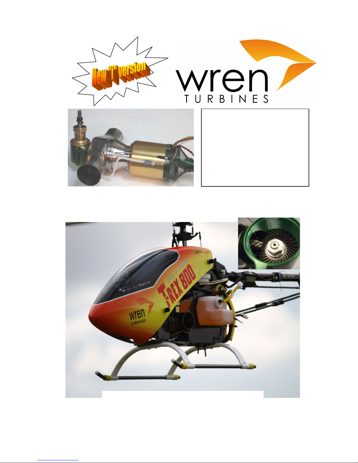
Unique, miniature gas turbine two-stage
engine, fully internal automatic starting
(no-gas req’d), kerosene fuelled,
precision gearbox.
Up to 7hp (5.2kw) of output shaft power
up to 20k rpm, for superb performance
in sport, scale or 3D aerobatics.
Gearbox matches OS91H dimensions
and accessories.
Many airframe conversions available.
Wren 44 Gold Helicopter Owners Manual Page
1
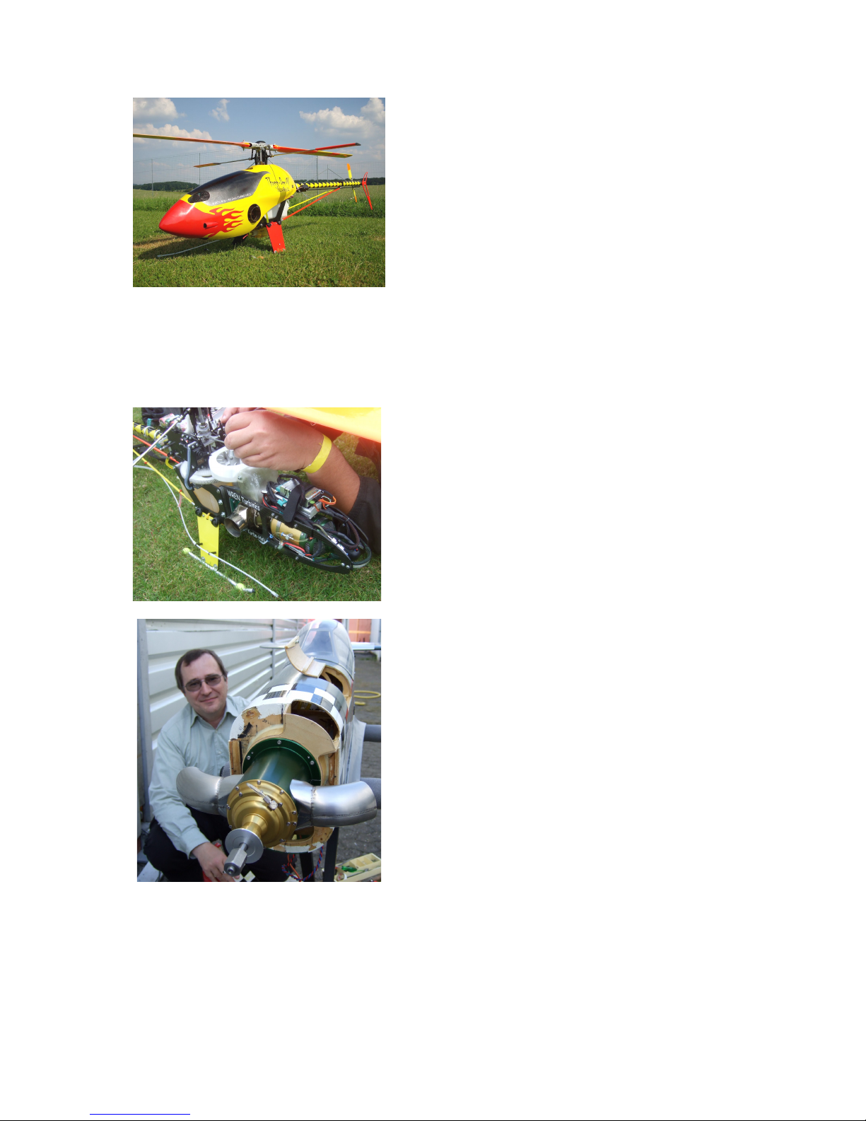
Front cover, Ian Erskines beautiful TRex 800, Wren 44Heli power, hmmmmm!
WREN 44i Turbine Helicopter Manual
Congratulations on your purchase of the latest version of our miniature Wren44 Helicopter
gas turbine engine. The new 44”i” means your heli engine now has the Wren kero burner
internal to the engine, no pipes or wires to get in the way of your installation!
This manual has been prepared to help you set up and safely operate your engine in your
airframe. If you encounter any problems then please consult this list first and if you cannot
find a solution please get in touch with us. The engine is simple to prepare and use but
certain precautions must be observed for your safety and others by you – see safety notes.
Included in the manual is a problem checklist to help solve any problems you may encounter
in operation. Please remember, although small and seemingly harmless the engine is
definitely not a toy and must be treated with utmost care and consideration to your own
safety and others around you. The manual also contains sections on the individual
components of the installation and operation, refer to these for more detailed information.
Contents:
3 Introduction
5 Package contents
5 Weights and measures
6 Specifications
7 Fuel consumption
8 General description
13 Ancilliaries
16 Safety notes
19 Installation
21 Autostart system
21 Radio setup
24 Failsafe function
25 Services schematic
26 Starting the engine
27 Setting a throttle curve
29 Problem checklist
31 Maintenance
32 Storage
33 Warranty
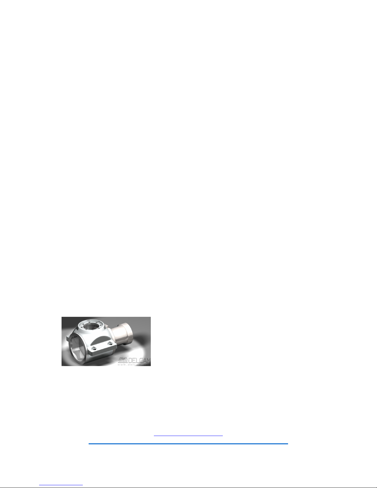
Precision CNC machined gearbox- fully 3D modelled for perfect
alignment and trouble free operation.
Too good to hide!
I’ve got my engine, which heli should I choose?
A question we are often asked is which is the ideal heli to use with the Wren 44Heli unit? It’s not an
easy question to answer as much depends on your skill as a builder and your idea of the perfect
machine. One fact is, the Align TRex 700 + 800 is by far the most popular choice of helicopter and is
very easy to get spares with endless upgrade opportunities. It is well supported with at least four
different conversion kits available to convert to the Wren Heli engine and lots of body options too.
Which to choose from, or to do your own is your choice.
See the Wren website for more details on the options and contacts:
www.wrenturbines.co.uk
https://www.facebook.com/pages/Wren-Turbines/154656198069224
Wren 44 Gold Helicopter Owners Manual Page
2
Wren 44 Helicopter Turbine
This unit is a unique miniature gas turbine engine driving through a small gearbox suitable
for driving the rotors on pod and boom sport helicopters 0.90cu in (15cc) size upwards and
with suitable additional gearing provides adequate power to fly scale helicopters and camera
platforms in excess of 50 lbs (23 kg) AUW.
New for 2014 includes new internal kerosene start system as standard, which eliminates all
the extra components required for propane start in a neat and tidy package.
The engine is usually supplied as part of a complete airframe package but it is not difficult for
the experienced builder to convert most large airframes to turbine power, or scratch-build
their own models. There are several interesting models featured on the Wren website at
www.wrenturbines.co.uk Whatever you are building, there are technical considerations and
aspects of safety specific to turbine models and we would like to offer some advice based on
our seven years experience designing two-stage turbine helicopters.
SAFETY
This section is intended to cover aspects of safety specific to turbine helicopters. The
manual does not cover the flying of the helicopter as it is assumed that the owner has prior
flying experience and that this would not be a first model. Turbines are NOT toys and
anyone building or operating a turbine helicopter must have suitable skills and experience.
FIRE
There is a small but real risk of fire when operating turbine powered models. Hot kerosene
ignites readily and it is almost impossible to put out the fire without a fire extinguisher. Only
carbon dioxide (C02) extinguishers are suitable as powder types will ruin the engine but in
an emergency use what you can. Do not operate your engine unless you have an
extinguisher at hand. If there is a fire inside the engine, try to direct the extinguisher into the
air inlet, otherwise attack the seat of the fire.
HOT PARTS
Turbines generate large quantities of hot gases and have parts that stay hot for a long time
after the engine has stopped. Both the exhaust gases and these parts are sufficiently hot to
cause serious burns. Make sure that anyone not familiar with turbine operation is aware of
this.
Critical components adjacent to hot parts may need protection or spacing away from heat
damage by distance or physical protection. An aluminium foil faced insulation material is
suitable for wrapping around hot parts of the engine and is available from Wren Turbines if
required.
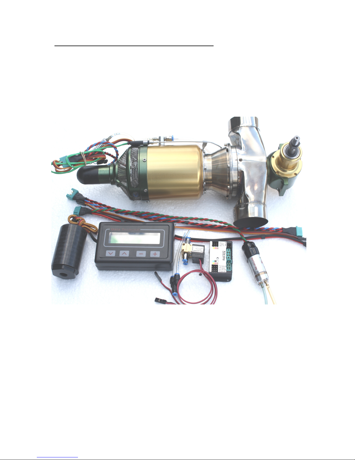
Even in a small airframe like the
Mark Symons Bergen Magnum
(left) the engine tucks in neat and
tidy and enables all the originally
supplied transmission and fan
components to be used.
The free flow of cooling air negated
the need for any further heat
resisting processes and proved a
trouble free install.
Wren 44 Gold Helicopter Owners Manual Page
3
The Wren 44 Helicopter Turbine
Introduction
This development from the highly popular Wren 44 Gold
thrust engine, has been on sale since 2005. It was built
on the success of the Wren 44 Turboprop and uses the
same engine and 2nd stage components. The Wren Heli
engine was the outcome of a long R&D programme
primarily concerned with maximising the performance and
minimising the aggravation of installing and operating,
allowing the flier to get on with the business of flying.
We have been careful to keep the weight of the unit down
but have not compromised stiffness, which has shown
itself to be a major concern for turbines. The gas turbine is
not modified for use in this application apart from a small
lubrication port fitted to the case, enabling the full
throughput to be used in driving the helicopter rotors,
producing performance usually described as “awesome”
by all those witnessing it and meaning it is never needed
to use maximum power, thus ensuring long life and ease of operation.
The gearbox assembly is strongly built to withstand many hours of operation and is designed
for lubrication with a fuel take-off from the engine. All this is automatic and the user need
only put fuel (clean!) into the tank, charge battery and go fly!
We have tried hard to produce a compact high power to weight engine capable of filling the
gap currently occupied by the noisy and smoky 90’size heli I/C engines and yet keep the
package bulk and weight down to allow simple conversion without throwing all the standard
parts away. There are a large number of airframes already available in the 15cc (0.90”) size
that are attractive for conversion to turbine for the reasons outlined above and are suited for
the average club flier to expert flier alike. The low installed weight around 1.4kg compares
well with equivalent 2-cycle engines plus tuned pipe and helps to keep the rotor loading
sensible.
A major plus factor for this engine is the mountings and output shaft dimensions are exactly
mirroring the standard OS91H helicopter engine, therefore any airframe, clutch and fan,
designed for this i/c engine will fit onto the 44 Heli engine.
The main areas for modification will be the fan shroud and main frames.
Remember - fit the black washer supplied onto the shaft before the clutch, to avoid
bearing damage
Wren 44 Gold Helicopter Owners Manual Page
4
Noise is becoming a major concern and the 44 Heli
enjoys a remarkably low noise figure, rivalling
electric models in many cases. The noise is
predominantly rotor noise and a low background
whistle, with the smooth application of torque and
total absence of power pulses enables a very low
perceived noise level to be achieved and which
dissipates very quickly with distance. This has
major implications for choice of flying site as those
in noise sensitive areas will benefit from the
absence of the irritating 2-stroke “buzz” associated
with normal i/c engined helis.
The Wren 44 Heli enjoys the same highly responsive engine as the Wren 44 Gold thrust
version so the absolute minimum throttle lag can be appreciated by those keen on the usual
aerobatics and 3D manoeuvres, though we would not pretend the engine can rival the
lightning fast response of a racing 2-stroke heli engine, but users will be pleasantly surprised
at the enormously wide power band enabling very simple throttle curve programming and
flying.
The small engine size (in turbine terms) enables the
fuel consumption to be described as “stingy” so no
need for dragging a big fuel tank around like typical
turbine heli’s, together with the c-of-g issues this
presents.
Importantly, the engine is already well established
so you are not buying an unproven design. Parts
and service is readily available and the hundreds of
Wren 44 Gold customers across the world will testify
to the longevity and ease of use of this worldbeating engine.
Above all – Be Safe and enjoy!
Special thanks to:
Lucien Gerard, a good friend and colleague of all at Wren
Turbines, who was the first customer to build a Wren 54
turboprop back in 2002 that flies a whole range of 44
powered models for us and encouraged this development
from the start.
Lucien installed and flight tested all the Wren 44 turboprop prototypes and was instrumental in development
and prototyping of the heli gearbox unit. He made the
conversions for the Align T-Rex700 and the Henseleit
ThreeDee MP-XL to enable the heli testing programme to
proceed. His generous help and feedback has greatly
assisted and encouraged us to take this unique
development to successful production and beyond.
Luciens two friends Oli Romanus and Greg Concalves (Wren-Team France) supplied the Henseleit
Three-Dee MP-XL and Align T-Rex700 helicopters that formed the basis of the Wren44 heli
conversion outlined in this manual. We send our grateful thanks for all their hard work and inspiration.
Above, Lucien with his conversion of the Great Planes P51 Mustang, converted to 44 TurboProp in September
2007. Just one of many switched to Wren 44 power.
Wren 44 Gold Helicopter Owners Manual Page
5
The Wren 44 Helicopter package contains the following:
1) Wren 44 Heli engine, complete with spacing washer and clutch nut
2) Fuel pump and harness
3) Autostart ECU (Engine Control Unit)
4) ECU data display terminal
5) ECU Battery (2-cell LiPo)
6) Fuel and kero burner solenoids (identical) + “Y” connector
7) Engine extension cable
8) Gearbox access plug removal tool
Weights
Power unit complete with cables 1320g (2.9 lbs)
Fuel pump 88g (3oz)
Valves 45g (1.6oz)
ECU (Engine Control Unit) 35g (1.25oz)
LiPo battery 7.4v, 1500mAh 80g (2.75oz)
Airborne weight 1570g (3.45Lbs)
Typical total heli weight 5.2-5.3kg (11.5Lbs)
Principle Measures
Output shaft diameter 3/8” + 5/16” UNF threaded portion (as per OS 91Heli)
Mounting dimensions – gearbox – as per OS91 Heli
Gearbox mounting holes 4off dia 4.2mm
Length overall, gearbox output shaft to tip of starter 305mm (12”)
Width – engine – 75mm (3”)
Wren 44 Gold Helicopter Owners Manual Page
6
4
4.5
5
5.5
6
6.5
7
7.5
7000 8000 9000 10000 11000 12000 13000 14000 15000
H
P
RPM
Output HP to Gearbox output RPM @ 195k
Height – total engine to tip of output shaft – 125mm (5”)
Width across exhausts – 160mm (6.3”)
Exhaust exit diameter – 45mm (1-3/4”)
Shaft nut size 12mm A/F
Kerosene burner voltage – 6.5v / 20w
Nominal fuel tank for most heli’s, 650-1000cc, 22-34oz (6 to 10mins flying)
Performance specifications
Practical rpm range – 4,000 to 18,000rpm, 3.24Nm, 7hp (5.3Kw) (engine to max 195k rpm)
Peak torque output – 4.05Nm @ 13300 rpm, 7.53hp (5.62Kw)
Peak rpm output – 18,700rpm, torque 2.15Nm, 5.65hp (4.2Kw)
Gearbox ratio - 2nd stage turbine to output shaft - 4.285:1
Nominal recommended maximum engine rpm for normal flying, 90 size heli – 175,000rpm
Nominal recommended maximum engine rpm for aerobatic/3D flying, - 185,000rpm
Maximum engine rpm for extreme 3D (strengthened main and tail rotors) - 195,000rpm
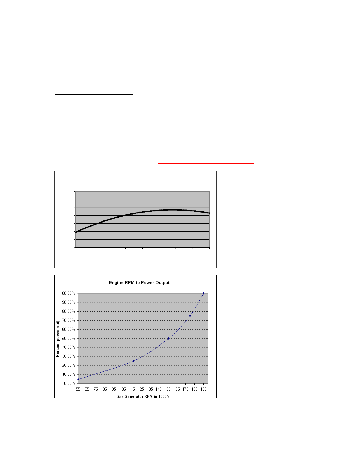
Chart showing shaft power
output at full engine rpm
Chart showing percentage power
output for scaling against engine
rpm’s.

Wren 44 Gold Helicopter Owners Manual Page
7
Fuel Consumption
0.0
1.0
2.0
3.0
4.0
5.0
6.0
5
5
1
0
0
1
3
0
1
6
0
1
8
0
1
9
5
C
o
n
s
u
m
p
t
i
o
n
i
n
f
l
/
o
z
p
e
r
m
i
n
Engine RPM x 1000
Fuel Consumption Fl/oz to Engine RPM
0.0
40.0
80.0
120.0
160.0
5
5
1
0
0
1
3
0
1
6
0
1
8
0
1
9
5
F
u
e
l
c
o
n
s
u
m
p
t
i
o
n
i
n
m
l
/
m
i
n
Engine RPM x 1000
Fuel Consumption in ml/min to Engine RPM
Charts showing the fuel
consumption used for the
unit in fl.oz/min
Charts showing the fuel
consumption used for the
unit in ml/min
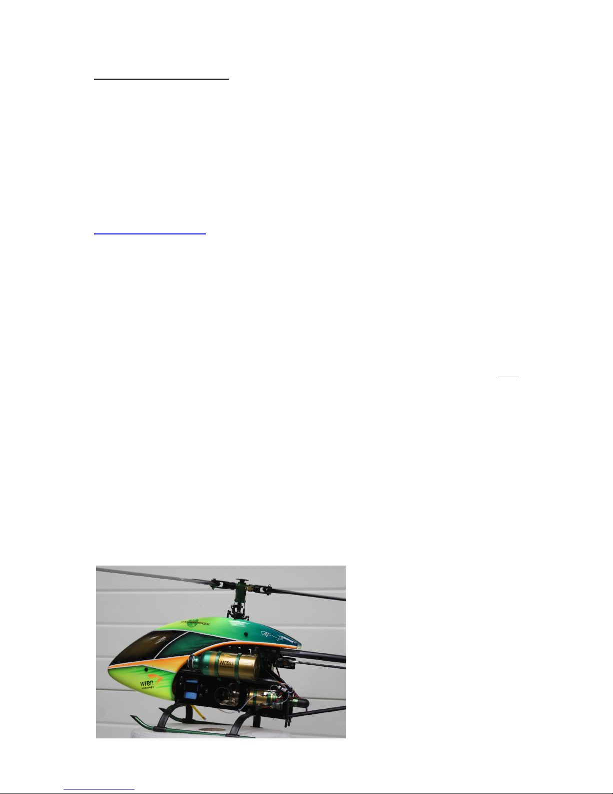
New heli for the Wren 44 unit
by Chris Bergen of Bergen
Helicopters – the Bergen
“Magnum 44” hmmmmm!
Wren 44 Gold Helicopter Owners Manual Page
8
General description of the Wren 44 two-shaft drive system
The following notes introduce the main parts of the assembly and offer an insight to the use
and operation of the unit as a whole;
The Wren 44 Helicopter Unit is the world’s smallest commercial 2-shaft helicopter engine. It
is designed for use in miniature helicopter applications in place of an I/C engine. It is
generally suited to helicopters up to 25kg (55lb) in all up weight and will replace I/C engines
of around 15-30cc (0.9 to 1.8cu inch).
What is a two-shaft system?
The two shaft drive system means there are two independent shafts running within the unit.
The first shaft is contained within the engine end of the unit and rotates at very high speed
(up to 195,000rpm) with just a small compressor wheel at one end and axial flow turbine at
other end. This forms the gas generator. The engine end of the unit generates a flow of gas
at high pressure and volume, and its operation is exactly as a small gas turbine engine. If a
nozzle was attached to the outlet of the engine it would imparts a slight squeezing of the gas
into a high velocity jet for producing jet thrust as would be the configuration for a thrust
engine. For a gas generator version of the engine, instead of squeezing the gas through a
nozzle it is redirected by another vane assembly to turn a 2nd turbine wheel mounted on the
2nd stage shaft. This is driven round in the gas stream and this rotation drives the input shaft
to the gearbox and onwards to the helicopter drive.
The 2nd turbine is larger in diameter (66mm) than the 1st
stage and runs much slower - up to only around 80,000rpm still far higher than any 2-stroke or electric motor could
achieve, but at a higher torque level. The energy given up by
the gas driving the 2nd stage turbine drastically reduces the
velocity of the exhaust gas with the result than only a small
residual thrust remains from the exhaust outlets.
What happens if I stall the output shaft in a bad landing?
In a situation that causes the output shaft to stall, the gas
generator will continue to function normally with little ill-effects. On releasing the shaft from
its stalled form it will spin back up to it's normal running speed. This should be born in mind
when retrieving the model from long grass or crash situation – never try to pick up the model
whilst the engine is running.
What sort of gearbox is required to convert the 2nd turbine speed to something I need?
The rpm generated by the large diameter 2nd stage turbine is from zero to around
75,000rpm depending on loading and gas generator flow. This enables a suitable reduction
to be contained in a simple single stage gearbox, the ratio of which is chosen to suit the
operational needs of the load driven. The 44Heli reduction is 4.285:1 and this gives an
output shaft speed range of zero-20,000rpm. The 2nd turbine has a wide operating rpm
range and may be slowed with high load or allowed to speed up with low load without
upsetting the 1st stage, therefore the choice of rotor blade or subsequent reduction beyond
the engine is not at all critical, providing it presents enough load for the system. The main
criteria for reduction ratio choice being the type of heli the unit is fitted to (scale, aerobatic,
sports etc) and the length of rotor blade required to be driven.
WARNING - it is most important that there must always be some load on the output
shaft as otherwise the 2nd stage turbine will be running unrestrained and may easily
speed up beyond it's safe running speed, even when the gas generator is running at
only a modest rpm.
The unit must NEVER be revved up without a suitable load attached.
Wren 44 Gold Helicopter Owners Manual Page
9
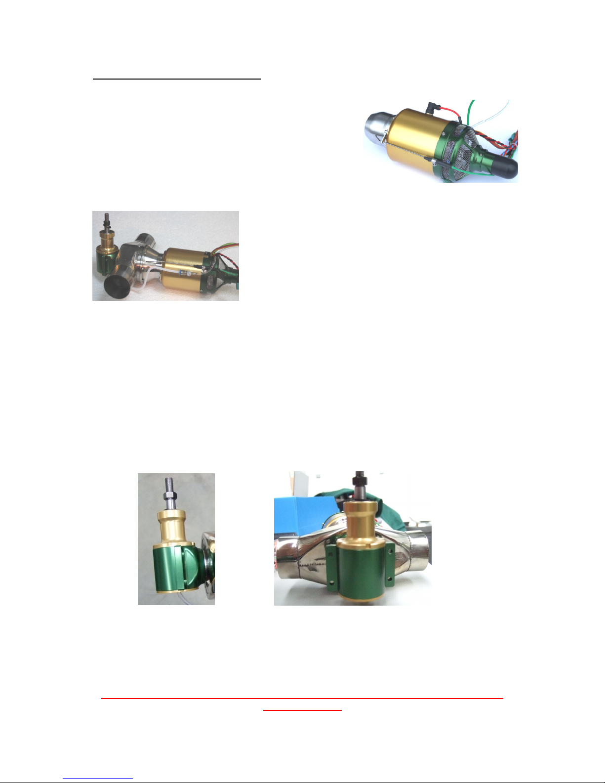
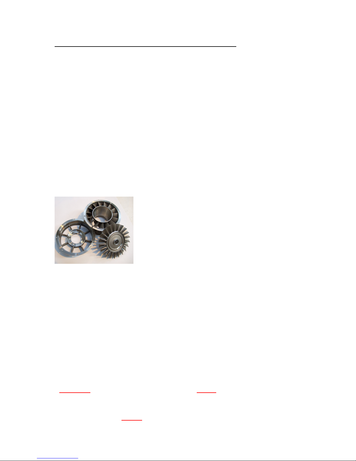
What is the gearbox arrangement?
The gearbox housing is made up of three pieces, the main gearbox body (green), output
housing and blanking cap (both gold) in the base. The output housing is not intended to be
undone by customers as it is preset with shims for correct gear backlash and loctited, so
please do not undo it. Any evidence of removal will void the warranty. The blanking cap in
the base of the gearbox can be removed and refitted and a shaped plastic tool to do this is
provided. No further dismantling of the engine or gearbox is permitted.
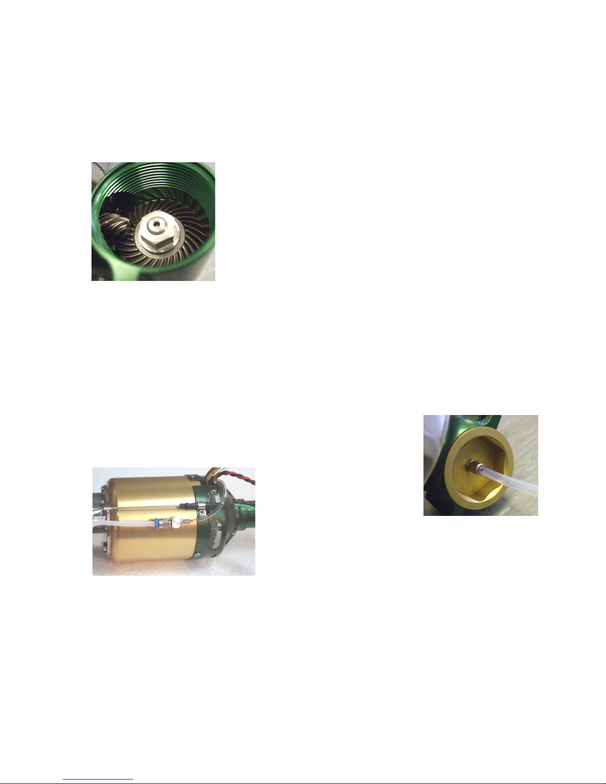
The front of the 2nd stage turbine shaft carries a specially
contoured spiral bevel gear which meshes to a sintered high
strength spiral bevel crown wheel. The input shaft is carried on
two high precision ceramic high speed bearings with a light
preload. The bearings are lubricated with fuel exiting from the
gearbox area. The reduction ration is 4.285:1 and the gear
assembly is safe to run to 20,000rpm output speed and
85,700rpm input. Normal maximum speed of this shaft plus
clutch and fan would be around 15 to 18,000rpm and remember
most tail rotor assemblies are speed rated for these rpm’s so
take extra care here.
The output gearshaft is supported by a pair of substantial bearings and a wiper type oil seal
to retain lubricant in the housing. It is intended that the supplied black washer is slipped on
first followed by clutch components which are tightened onto the inner ring of the output
bearing. This pulls the crown gear into the precise mesh preset at the factory. A securing nut
of the standard pattern is provided for securing the shaft accessories, clutch etc.
The gearbox housings are anodized to resist corrosion and maintain their lustre. The gears
are fully hardened and are able to run with long life using just a small amount of engine fuel
bled off the gas generator fuel system. The oil percentage in the fuel should be 5% to ensure
satisfactory lubrication.
A hole up the middle of the tool enables the pipe to be fed up the
middle while removing and refitting the cap – keep a clean cloth handy
to catch any remaining lube. The cap is fitted with a sealing O-ring so
there is no need for excessive torque to be used in refitting it.
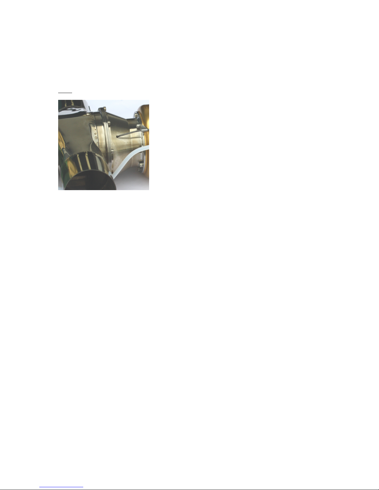
Lubricant is tapped off the main
engine pressurized fuel supply
and fed with a small amount of
air pressure via a mixing nozzle
to the bottom of the gearbox.
As the gearbox can get hot in operation the feed pipe
is a clear 4mm PTFE heat resistant tube retained to
the blanking cap on the gearbox by a knurled screw
fitting. Be careful when routing in and around this tube,
to avoid kinks that might close off the lubrication supply. If you do get a bad kink, ask for a
new pipe, don’t risk ruining your unit by running it dry.
Do not disconnect the PTFE pipe at blanking cap end as it is extremely difficult to do so
without damaging it and it may leak if disturbed. Disconnect only on the Festo fitting on the
engine and leave the PTFE tube attached to the cap. If the tube end starts getting chewed
then slice the last few mm off with a sharp knife (not side cutters).
When you receive your unit you might try to rotate the output shaft and find it tight. This is
because the output shaft bearings are spring loaded and without the clutch fitted in position
the spring can push the gear into tight mesh. When the clutch is fitted it should then mesh
correctly and rotate smooth and sweetly.
Wren 44 Gold Helicopter Owners Manual Page
10
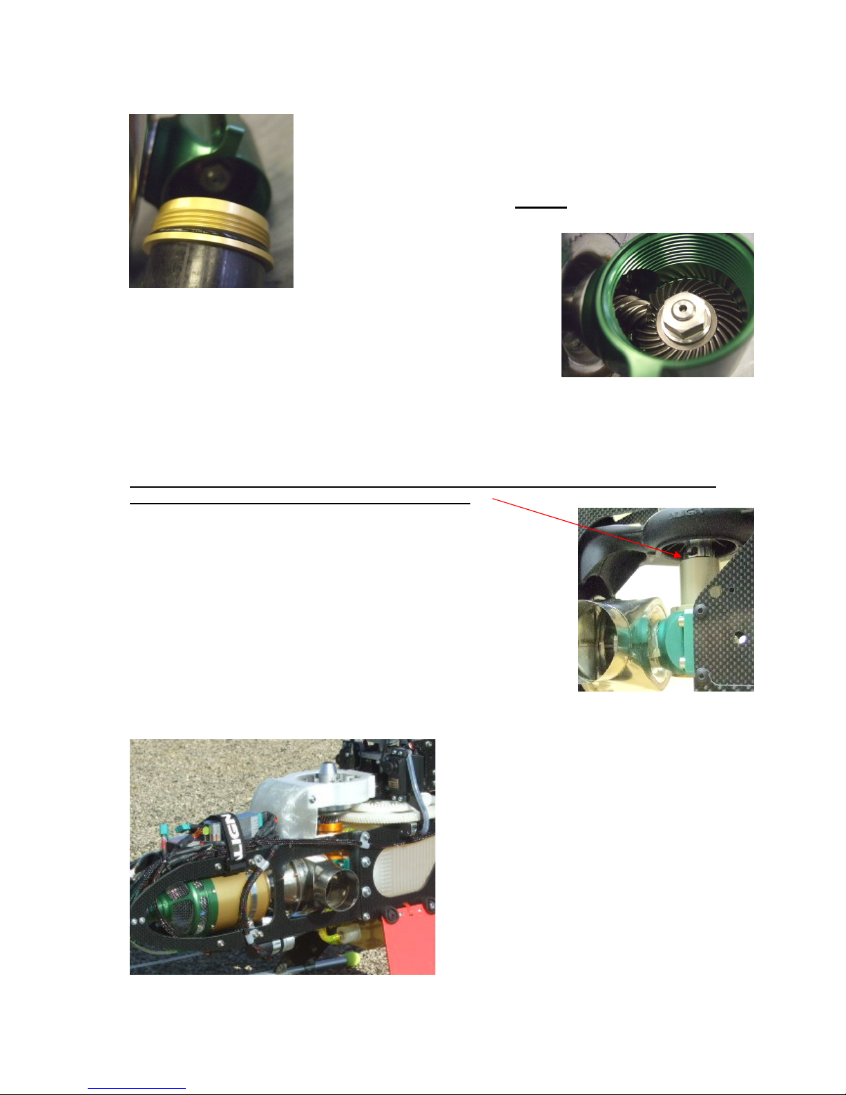
How do I lock the output shaft to fit my clutch and fan components?
To enable the output shaft to be locked for attaching output
components, clutch etc, unscrew the lower part of the gearbox
using the simple plastic tool supplied. DO NOT attempt to jam
the gearbox shaft by sticking a screwdriver or metal rod in
between the 2
nd
stage turbine blades – you may cause severe
damage to the blades and this will not be covered under the
warranty.
After removal of the access cap use a
clean 12mm A/F socket or ring
spanner to the large nut at the inner
end of the shaft (which is high-strength loctited to the shaft) to lock
the shaft and enable the supplied washer to be fitted to output
shaft first, followed by clutch, fans etc, followed by securing nut.
Be extra careful to keep everything clean here and do not leave
the gearbox interior exposed as dirt particles getting in will
eventually be washed into the turbine bearings as soon as the engine is started up and this
may cause permanent damage to the bearings. As we cannot control access to the gearbox
interior we cannot warranty 2nd stage turbine bearings, however such access has not proved
to be a concern in the development testing.
It is most important the black washer supplied is fitted before the clutch unit so the
clutch cannot foul the top bearing on the gearbox.
What is the effect of forward airspeed on the engine?
Once the helicopter is in the air and traveling forwards the rotor rpm
will increase as its load reduces with forward speed. An rpm increase
of 10-15% can be expected in the air so choose a pitch setting that
keeps the output speed below the rotor safe maximum.
It is this increase in rotor rpm in the air which gives the turbo-shaft
powered aircraft a high airspeed capability and shows a definite
edge over it's I/C engine counterpart. I/C engines have a more
limited unloaded speed capability, as it can result in the engine
mixture strength "leaning out" which can cause engine damage. By
contrast the turbo-shaft engine will enjoy running cooler as the rotor speed unloads leading
to longer life and reduced loading on critical components.
How is the unit it mounted in the airframe?
The unit is housed on the standard i/c
engine bearers provided in the heli
airframe, by the four M4 mounting holes
provided on the gearbox.
The output shaft will then be presented in
the correct position for the clutch and fan
components as per the normal i/c engine
install.
Support is required for the main body of
the engine forward of the gearbox and
simple aluminium or stainless steel strap
around the engine will suffice.
Wren 44 Gold Helicopter Owners Manual Page
11
There are several kits for conversions to the popular helicopter airframes. Each has its own
method of securing the engine but all are simple and effective. Allowance for heat expansion
of the unit should be considered in the mounting.
The aim is to eliminate engine movement while attached firmly via the gearbox as this places
very high point loads on the hot section coupling point in the centre of the unit and at the
gearbox fixings. Note that 3D flying imposes extremely high forces onto the unit and these
must be controlled by a suitably rigid mount.
Heat issues?
The exposed metal components between the engine and
exhaust are called the interstage and will get very hot in
normal use. The standard fan and shroud supplied for i/c
engine use is ideal to help control this and will help to
prevent damaging buildup of heat in the immediate vicinity
of the helicopter airframe.
There is no possibility of keeping the unit cool to touch –
the gas flow internally will be at 400-500’C and releases
over 100kw energy per second but these components are
designed to withstand this heat without problems. Aim just
to stop other parts being affected by the heat. Bear in mind
too, these parts will retain heat for a considerable time after shutdown so please be
extremely careful with fingers in this area.
In normal running the gold part of the engine casing will only reach about 100-130'C
minimizing the chances of heat damage to the aircraft fuselage and as long as some airflow
can get in and around. No further stiffening is required or advised for the unit, this approach
enabling the conversion from I/C engine to turbo-shaft power to be accomplished with ease.
The mounting should support the engine at the approximate centre of gravity to withstand all
normal loads such as might be subjected to during flying maneuvers.
Aren't gas turbines more dangerous than I/C engines?
No. Turbine fuel has a high flashpoint which means at normal ambient temperatures it is
extremely difficult to ignite, unlike gasoline or glow fuel which is a low vapour temperature
and ignites easily. The 2nd stage fully encloses the outlet of the gas turbine section affording
a high degree of protection against any component failure due to accidental damage or
persistent operation beyond the normal operational duty cycle. The main issues of concern
are the requirement for a high degree of structural integrity with the helicopter framework
and mechanics, and need to operate the power unit within the capabilities of the helicopter
main components like main and tail rotors. As there is little control possible over the choice
of airframe the engine is fitted to it is important the user considers carefully the power
settings and choice of components used before running the unit.
What's it like to operate?
“Magic” – customer quote! The power unit itself is operated as a normal miniature gas
turbine and possesses all the standard qualities such as automatic push-button starting and
cooling, totally vibration free operation, very quiet running and exceptional power and of
course has the “right” noise and smell. The throttle response is of the best in its class - the
small gas generator rotor is small and light allowing very quick spooling to be achieved
safely. Being a very small gas turbine its fuel consumption has been described as "stingy" a typical 10minute flight being easily achieved with a single 1ltr fuel tank, depending on the
flying style.
How does it compare to I/C power?
The exceptional power to weight ratio which is close in performance levels to an 80cc
 Loading...