

Wren Solution SDR6-IP User Manual
SDR6-IP, IP-Enabled 6” Solution Dome
Overview
The IP-Enabled Recessed Solution Dome line delivers attractive, durable products
for indoor security. Solution Domes are an excellent value------well-built, well-priced
and designed for easy installation and maintenance.
Suggested Installation Equipment
• #2 Phillips-head screwdriver
• Pliers (optional, for DC power)
• Proper tool for cutting mounting hole
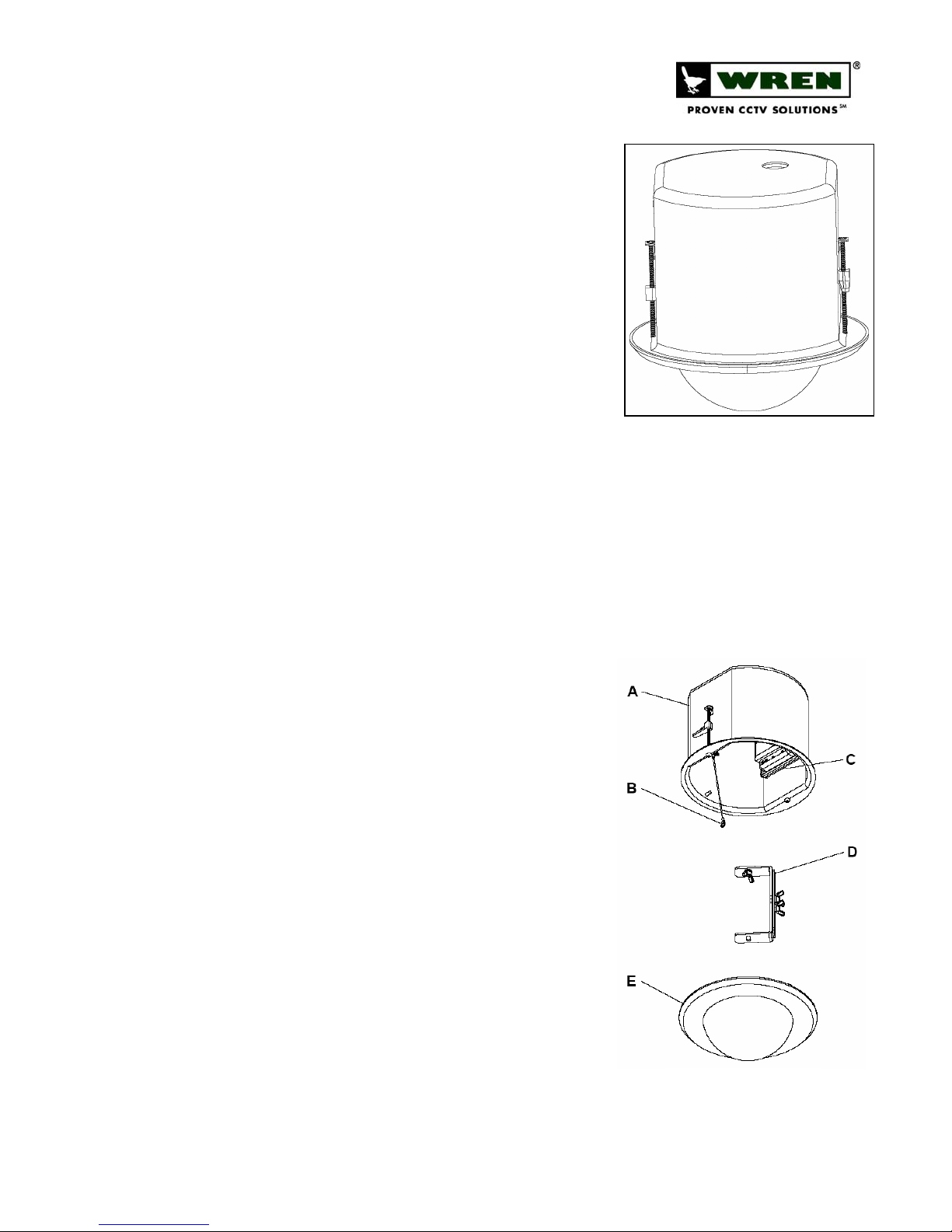
Component List [Figure 1]
A. Upper Housing Assembly
B. Safety Tether
C. Encoder Module
D. Camera Bracket Assembly
E. 8’’ Dome Assembly
F. Power Lead Extension and Connectors (not shown)
G. Wing Screw (not shown)
Warnings and Safeguards
Prior to installation and use of this product, please observe the following
warnings
1. Installation and servicing should be done by qualified personnel, and all
work done should conform to local codes.
2. Using replacement parts or accessories other than Wren may invalidate
the warranty.
3. Use only Wren-approved replacement parts or supplied accessories.
Failure to comply may invalidate remaining warranty period.
4. This unit is designed to operate on either IEEE 802.3af POE or 12VDC
power. Do not bring any other voltages into the housing.
5. Make sure that the installation method is capable of supporting three (3)
times the weight of the SDR6-IP housing and enclosed contents.
6. Verify proper installation of cabling to support camera power and
communication requirements for fixed camera applications.
Preparation
1. Carefully unpack box and verify that all components listed are included
[Figure 1].
2. Remove the Dome and Trim Ring Assy from the upper housing by
turning the assembly counter-clockwise, taking care that dome does not
become scratched or damaged.
www.wrenassociates.com (800) 881-2249
SDR6-
Indoor IP Solutions:
IP
6” Solution Dome
FIGURE 1
7L248-revA (08-15-2006)
Page 1 of 3
SDR6-IP, IP-Enabled 6” Solution Dome
3. Remove ceiling tile from desired mounting location and use the
support plate as a template to cut a hole into the ceiling tile. Ensure
that the hole is in the center of the tile.
4. Run Cat5 (and, optionally, 12VDC leads) to the location where the
assembly is to be installed.
POE power must be IEEE 802.3af compliant. Optional 12VDC power
NOTE
Installation
1. Place upper housing through hole from underneath ceiling tile. Place support
2. The anchor clips will twist over the support plate. Screw the anchor clips down until the upper housing is snug.
3. Connect the Cat5 cable to the RJ45 jack on top of the upper housing assembly. If 12VDC direct power is required,
must be from a regulated power source and of the correct polarity
(center positive). (See Master Power Supply Instructions for
wiring/installation instructions.)
plate behind housing. Using Philips-head screwdriver, turn the locking bolts
clock-wise in order to spin the anchor clips into locking position (outward).
DO NOT OVER-TIGHTEN.
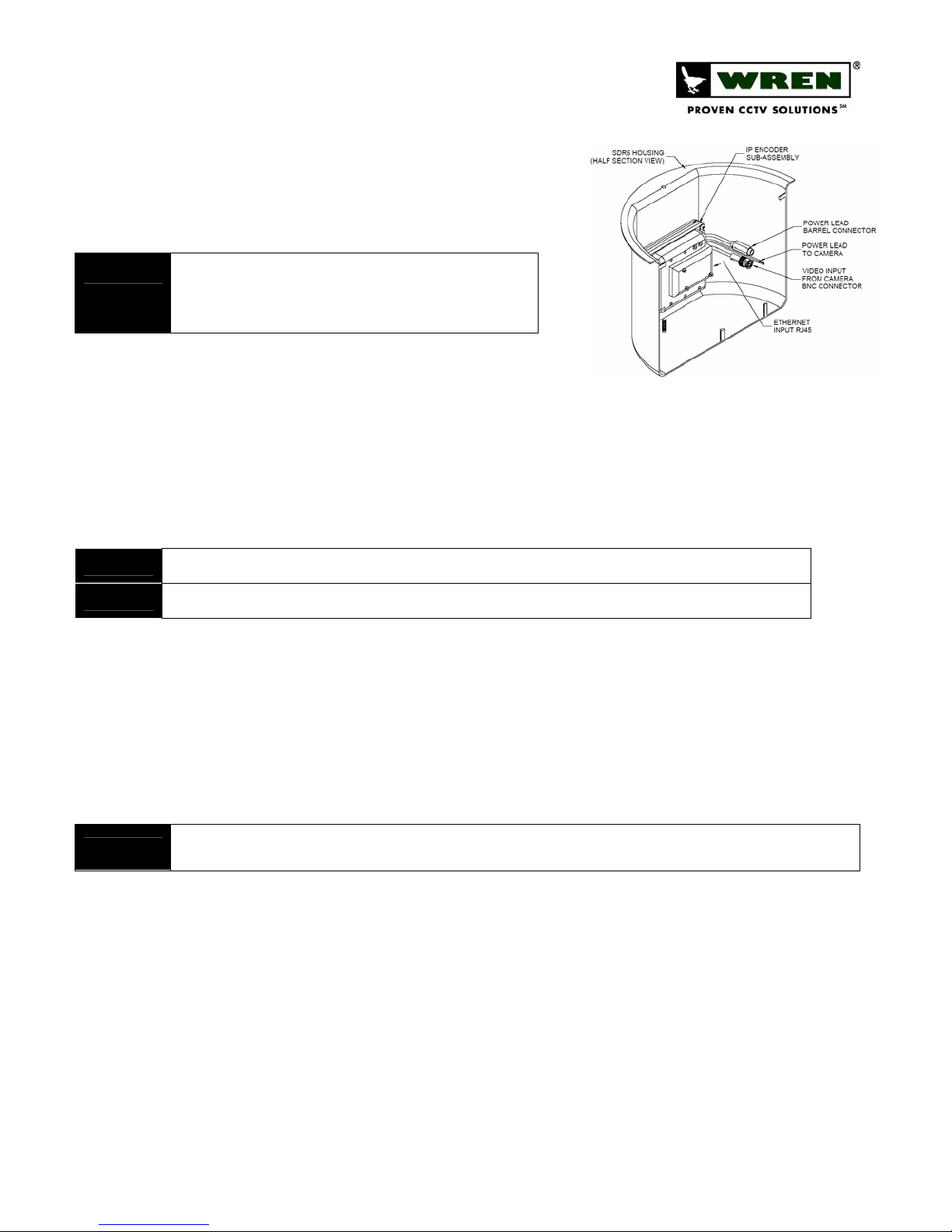
attach the included DC barrel connector pigtail to the power leads using the provided butt connectors, and
connect it to the barrel connector lead on the unit. [Figure 2]
FIGURE 2
TIP
WARNING!
4. The three
5. Attach the camera to the bracket using the 1/4-20 x 3/8’’ wing screw provided.
6. Connect power and video leads from the encoder assembly to the camera. Consult camera instructions for polarity
7. Replace Ceiling Tile (with housing installed) into the opening from which it was removed.
8. Make final pan and adjustments to achieve the desired shot and hand tighten knurled knobs to secure. To make
NOTE
To use Butt Connectors, twist the leads together, place joined leads into wide end of connector, crimp with pliers.
Ensure properly polarity (center positive) when connecting 12VDC. Applying incorrect voltage or polarity will invalidate warranty.
(3)
piece bracket is assembled and installed in the housing at the factory. Bracket need not be removed
from the housing for camera installation.
requirements. [Figure 2]
adjustments to the lens settings, loosen the lens locking screws, adjust focal length and focus, and retighten the
lens locking screws.
DO NOT use liquid cleaners (except for those that are specifically designed for optical-grade acrylic) on the Dome as they may degrade the
optical quality.
Troubleshooting
1. Software cannot connect to SDR6-IP, and no LED’s are lit:
a. Verify proper insertion of Ethernet cable at both ends of cable (if using POE). If LED’s are still not lit,
12VDC (center pin positive) can be connected to the optional power input to verify operation of the
SDR6-IP.
b. Verify proper voltage and polarity (if using direct power).
2. Software cannot connect to SDR6-IP, but some LED’s are lit:
a. Red LED indicates that the unit is getting power, and should be solid red. Green LED indicates network
status and should be blinking consistently if everything is working normally.
b. If red LED is on and green LED is not flashing, check Ethernet connections on both ends.
www.wrenassociates.com (800) 881-2249
7L248-revA (08-15-2006)
Page 2 of 3
 Loading...