

Wren Solution SDP6-IP Install Manual
SDP6-IP, IP-Enabled 6” Solution Dome
Overview
The IP-Enabled Pendant Solution Dome line delivers attractive, durable products
for indoor security. Solution Domes are an excellent value------well-built, wellpriced and designed for easy installation and maintenance.
Suggested Installation Equipment
• #2 Phillips-head screwdriver
• Pliers (optional, for DC power)
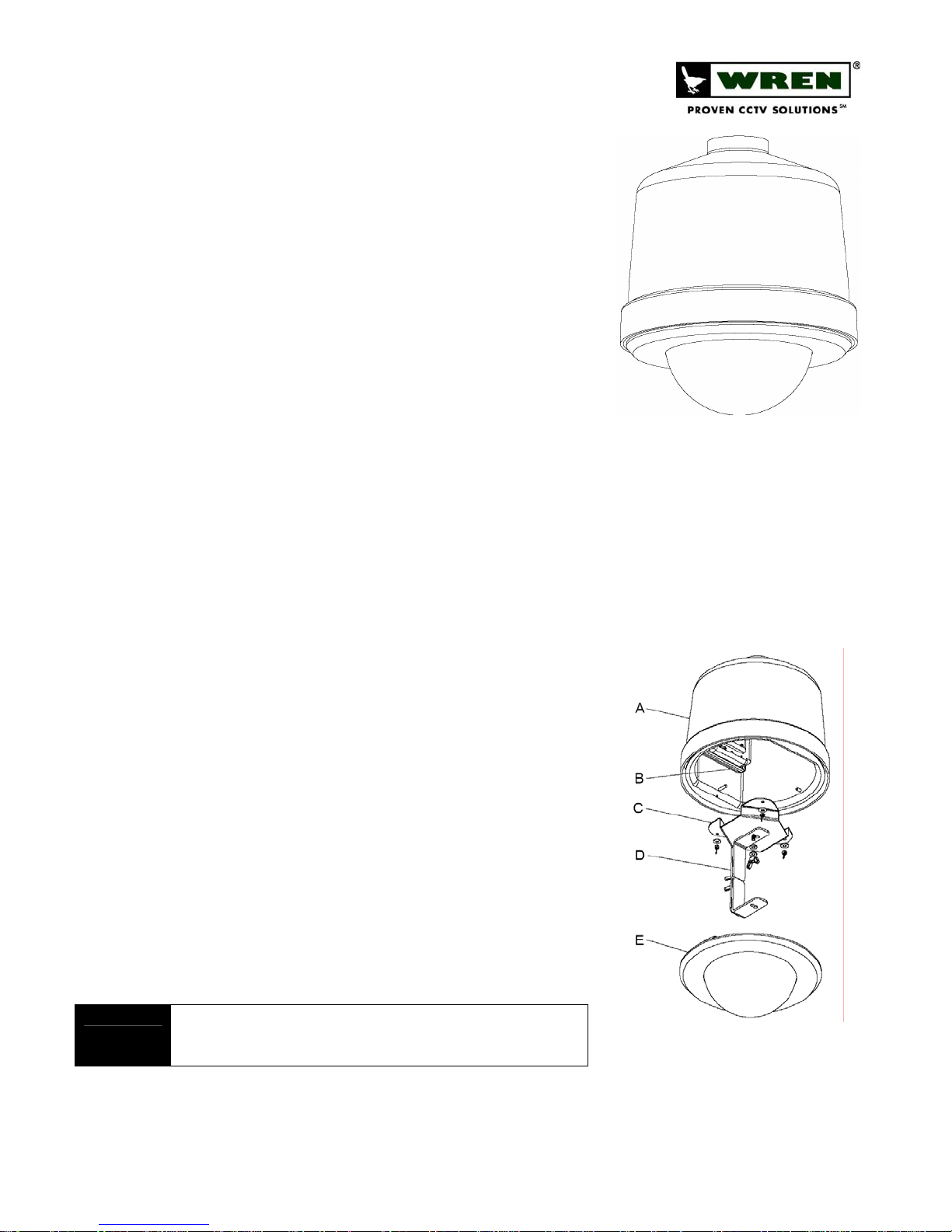
Component List [Figure 1]
A. Upper Housing Assembly
B. Encoder Module
C. Fixed Camera Bracket
D. Three-Piece Camera Mounting Bracket
E. 6’’ Dome Assembly
F. Power Lead Extension and Connectors (not shown)
G. Wing Screw (not shown)
Warnings and Safeguards
Prior to installation and use of this product, please observe the
following warnings
1. Installation and servicing should be done by qualified personnel,
and all work done should conform to local codes.
2. Using replacement parts or accessories other than Wren may
invalidate the warranty.
3. This unit is designed to operate on either IEEE 802.3af POE or 12VDC
power. Do not bring any other voltages into the housing.
4. Make sure that the installation method is capable of supporting three
times the weight of the SDP6-IP housing and enclosed contents.
5. Verify proper installation of cabling to support camera power and
communication requirements for fixed camera applications.
Preparation
1. Carefully unpack box and verify that all components listed are included
[Figure 1].
2. Remove the Dome and Trim Ring Assy from the upper housing by turning
the assembly counter-clockwise, taking care that dome does not become
scratched or damaged.
3. Remove the fixed camera bracket and the three
bracket by removing the 3 wing nuts securing it to the SDP6 housing.
4. Run CAT5 (and, optionally, 12VDC leads) to the location where the
assembly is to be installed.
POE power must be IEEE 802.3af compliant. Optional 12VDC power must be from
NOTE
a regulated power source and of the correct polarity (center positive). (See Master
Power Supply Instructions for wiring/installation instructions.)
(3)
piece mounting
(3)
Indoor IP Solutions:
SDP6-
IP
6” Solution Dome
FIGURE 1
www.wrenassociates.com (800) 881-2249
7L257-revA 9/1/2006
Page 1 of 3
SDP6-IP, IP-Enabled 6” Solution Dome
Installation
1. Install SDP6 assembly on 1½’’ NPT pipe or mount by rotating
counter-clockwise until threads are fully engaged.
(3)
2. Reinstall the fixed camera bracket and the three
bracket.
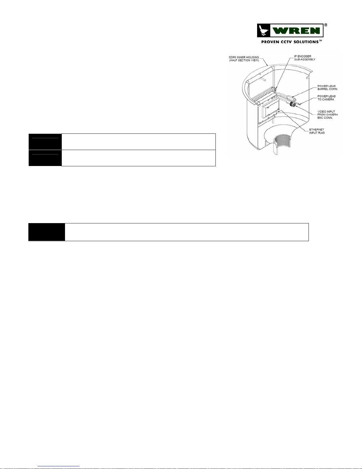
3. Connect the CAT5 cable to the RJ45 jack on the IP encoder sub-
assembly inside the housing. If 12VDC direct power is required,
attach the included DC barrel connector pigtail to the power leads
using the provided butt connectors, and connect it to the barrel
connector lead on the unit. [Figure 2]
TIP
WARNING!
4. Attach the camera to the bracket using the 1/4-20 x 3/8’’ wing screw provided.
5. Connect power and video leads from the encoder assembly to the camera. Consult camera instructions for polarity
6. Make final pan and adjustments to achieve the desired shot and hand tighten knurled knobs to secure. To make
NOTE
To use Butt Connectors, twist the leads together, place joined leads into wide end
of connector, crimp with pliers.
Ensure properly polarity (center positive) when connecting 12VDC. Applying
incorrect voltage or polarity will invalidate warranty.
requirements. [Figure 2]
adjustments to the lens settings, loosen the lens locking screws, adjust focal length and focus, and retighten the
lens locking screws.
DO NOT use liquid cleaners (except for those that are specifically designed for optical-grade acrylic) on the Dome as they may
degrade the optical quality.
piece mounting
FIGURE 2
Troubleshooting
1. Software cannot connect to SDP6-IP, and no LED’s are lit:
a. Verify proper insertion of Ethernet cable at both ends of cable (if using POE). If LED’s are still not lit,
12VDC (center pin positive) can be connected to the optional power input to verify operation of the
SDP6-IP.
b. Verify proper voltage and polarity (if using direct power).
2. Software cannot connect to SDP6-IP, but some LED’s are lit:
a. Red LED indicates that the unit is getting power, and should be solid red. Green LED indicates network
status and should be blinking consistently if everything is working normally.
b. If red LED is on and green LED is not flashing, check Ethernet connections on both ends.
3. Software can attach to SDP6-IP, but no video is present:
a. Use a voltmeter to check voltage on camera cable leads to be sure they read 12V.
b. Check video output from the camera with a separate monitor.
c. Ensure that ‘‘MiniGlobe’’ device is selected for the subject IP address in Wren VMS under Edit Camera.
d. If viewing through Internet Explorer (‘‘IE’’), ensure that the ActiveX control has been installed (see
Windows and/or IE instructions for details on permitting the installation of ActiveX controls).
4. See also: Troubleshooting section in Wren VMS instructions.
5. Wren Technical Support is available from 8am to 5pm CST Mon-Fri at 1-800-881-2249.
www.wrenassociates.com (800) 881-2249
7L257-revA 9/1/2006
Page 2 of 3
 Loading...