

Wren Solution MGW-IP Install Manual
IP MiniGlobe, Wall Mount
Instructions
DESCRIPTION
The Wall-Mounted IP MiniGlobe (MGW-IP) is an integrated solution
including a high-quality camera, lens and housing. Like all Wren products,
it is designed for quick and simple installation and servicing.
SUGGESTED INSTALLATION EQUIPMENT
• #1 Phillips-head screwdriver, for dome and housing screws
• #2 Phillips-head screwdriver with a long (at least 6”) shaft, or
other appropriate tools for installing mounting hardware.
• Pliers
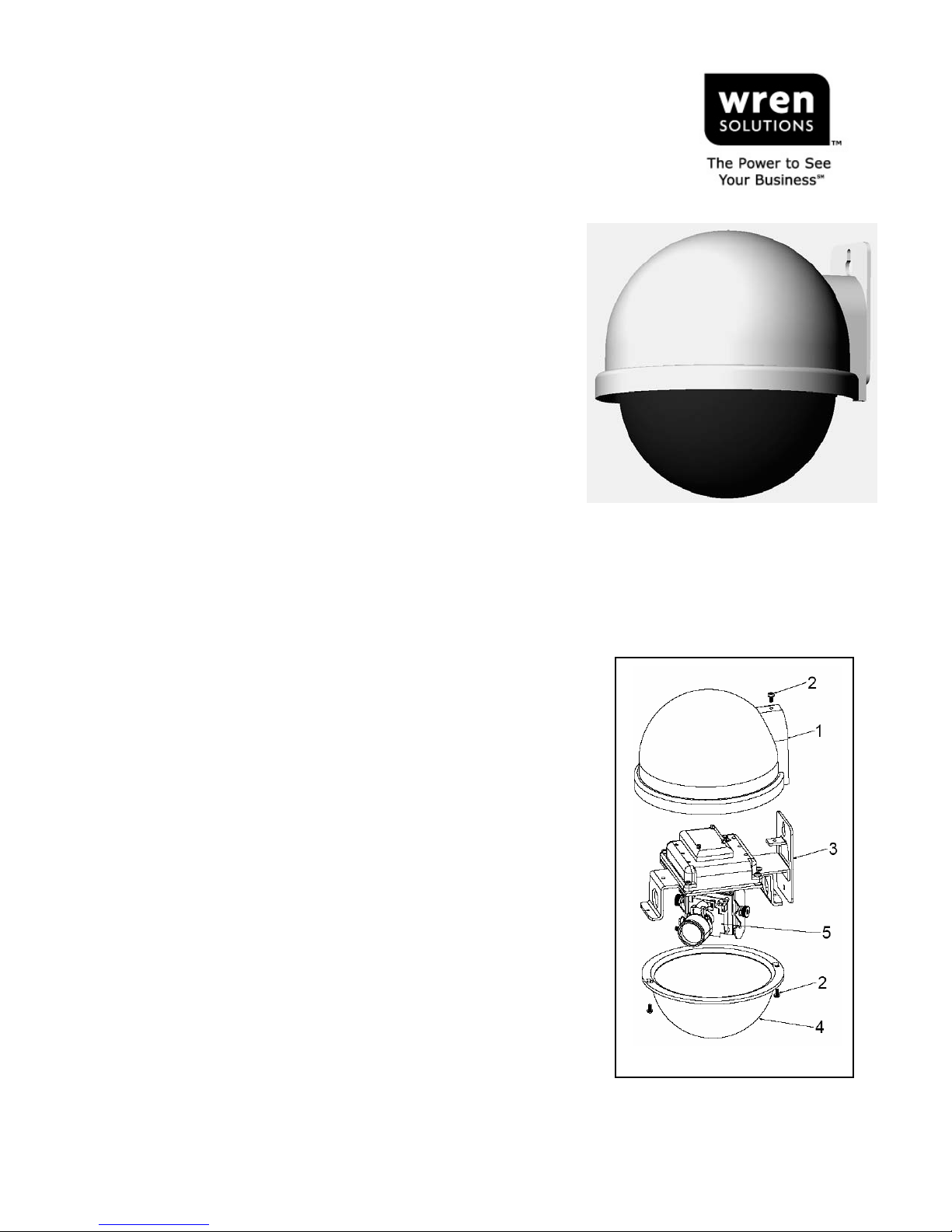
COMPONENT LIST [Figure 1]
1. Upper Housing
2. #4-40 screws (3)
3. Main Bracket Assy
4. Dome
5. Camera Assy
6. #8 Pan-Head Sheet-Metal Screws (2) (not shown)
7. DC Power Pigtail (not shown)
8. Butt Connectors (2) (not shown)
WARNINGS AND SAFEGUARDS
Prior to installation and use of this product, please observe the following
warnings:
1. Installation and servicing should be done by qualified personnel, and
all work done should conform to local codes.
2. Using replacement parts or accessories other than Wren may
invalidate the warranty.
3. This unit is designed to operate on either IEEE 802.3af POE or
12VDC power. Do not bring any other voltages into the housing.
4. Make sure that the installation method is capable of supporting
three (3) times the weight of the MGW-IP housing and enclosed
contents.
PROPERTY OF WREN Page 1 of 4 7L237 REV-C 9/21/2007
124 WREN PARKWAY • JEFFERSON CITY, MO 65109 • TOLL FREE (800) 881-2249 • FAX (877) 893-2317
www.wrensolutions.com
MINIGLOBE CAMERAS:
???
High-Resolution Color Board
Camera
INDOOR IP HOUSINGS:
MGW-IP
IP MiniGlobe, Wall Mounted
Figure 1
PREPARATION
1. Carefully unpack box and verify that all components listed are
included [Figure 1].
2. Remove the dome assembly from the upper housing by
loosening the two (2) black #4-40 Phillips-head screws with a
#1 Phillips screwdriver. Twist dome counter-clockwise slightly
to align the screw heads with the keyhole openings in the
dome, remove and set aside, taking care that dome does not
become scratched or damaged.
3. Remove the camera assembly from the hanger bracket by hand-
loosening the knurled knobs and sliding the camera out (do not
remove knobs). Carefully, place camera aside.
4. Remove the Upper Housing from the Main Bracket Assy by
removing the black #4-40 Phillips-head screw with a #1 Phillips
screwdriver.
5. Lay out the required mounting hole pattern (see figure on last page) in desired installation location and
drill holes as required. The top and bottom holes should accommodate the selected mounting hardware,
while the middle hole must be big enough to provide clearance for the cables coming into the housing.
6. Run Cat5 (and, optionally, 12VDC leads) to desired location and through the cable access hole drilled in
the previous step.
POE power must be IEEE 802.3af compliant. Optional 12VDC power must be
NOTE
from a regulated power source. (See Master Power Supply Instructions for
wiring/installation instructions.)
INSTALLATION
1. Install #8 Phillips-head screw (or other suitable hardware) into both holes in wall and leave approximately
1/8” to 3/16” gap between screw head and wall or vertical surface.
2. Feed Cat5 (and, optionally, the 12VDC power leads) through the mounting plate access hole.
3. Install upper housing onto wall by aligning the lower screw with the slot in the bracket and then aligning
the upper keyhole slot over upper screw and sliding the housing downward until seated. Tighten both
screws until snug, but DO NOT OVER-TIGHTEN.
4. Connect the Cat5 cable to the RJ45 jack. If 12VDC direct power is required, use the included DC Power
Pigtail and butt connectors and connect it to the power barrel lead (center pin is positive).
TIP
WARNING!
To use Butt Connectors, twist the leads together, place joined leads
into wide end of connector, crimp with pliers.
Ensure properly polarity when connecting 12VDC (center pin positive).
Applying incorrect voltage or polarity will invalidate warranty.
5. Push cable(s) back into mounting surface to remove excess slack.
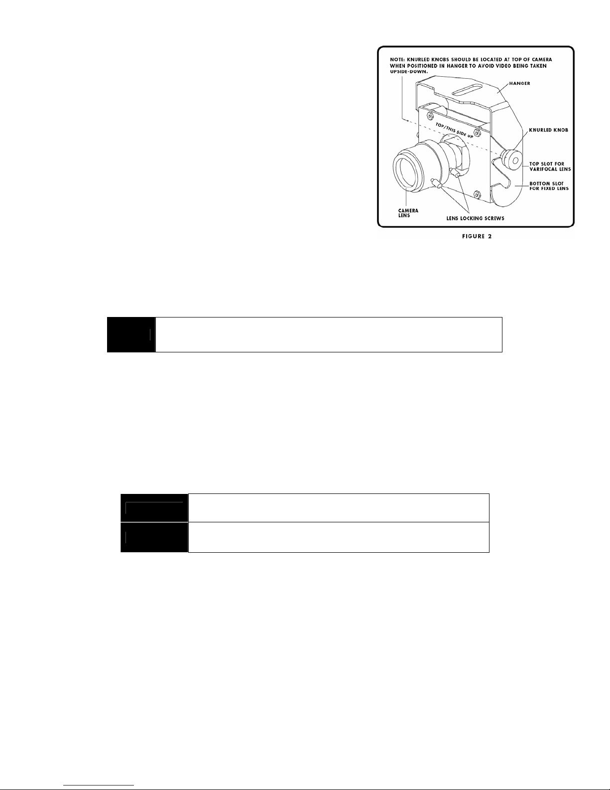
6. Place camera into hanger bracket and connect the camera cable. See Figure 2 for proper camera
orientation.
7. Make final pan and tilt adjustments and hand tighten knurled knobs to secure. [Figure 2]
8. To make adjustments to the lens, loosen the lens locking screws, adjust focal length and focus, and
retighten the lens locking screws snuggly (but do not over-tighten). [Figure 2]
9. Re-install Upper Housing onto bracket and secure with single #4-40 screw.
PROPERTY OF WREN Page 2 of 4 7L237 rev-C 9/21/2007
124 WREN PARKWAY • JEFFERSON CITY, MO 65109 • TOLL FREE (800) 881-2249 • FAX (877) 893-2317
www.wrensolutions.com
 Loading...