

Page 1
EG8-IP, IP-Enabled 8”
Environmental Globe
Instruction Sheet
Overview
The IP-Enabled Environmental Globe (EG8) is an attractive, durable
solution for outdoor applications accommodating a single fixed camera. It
is an ideal solution for situations where reliability and aesthetics are
important such as retail, property management, commercial and industrial
facilities
Suggested Installation Equipment
a. #2 Phillips-head screwdriver
b. 7/16” Wrench or socket
c. Outdoor-approved pipe thread sealant (included)
Component List
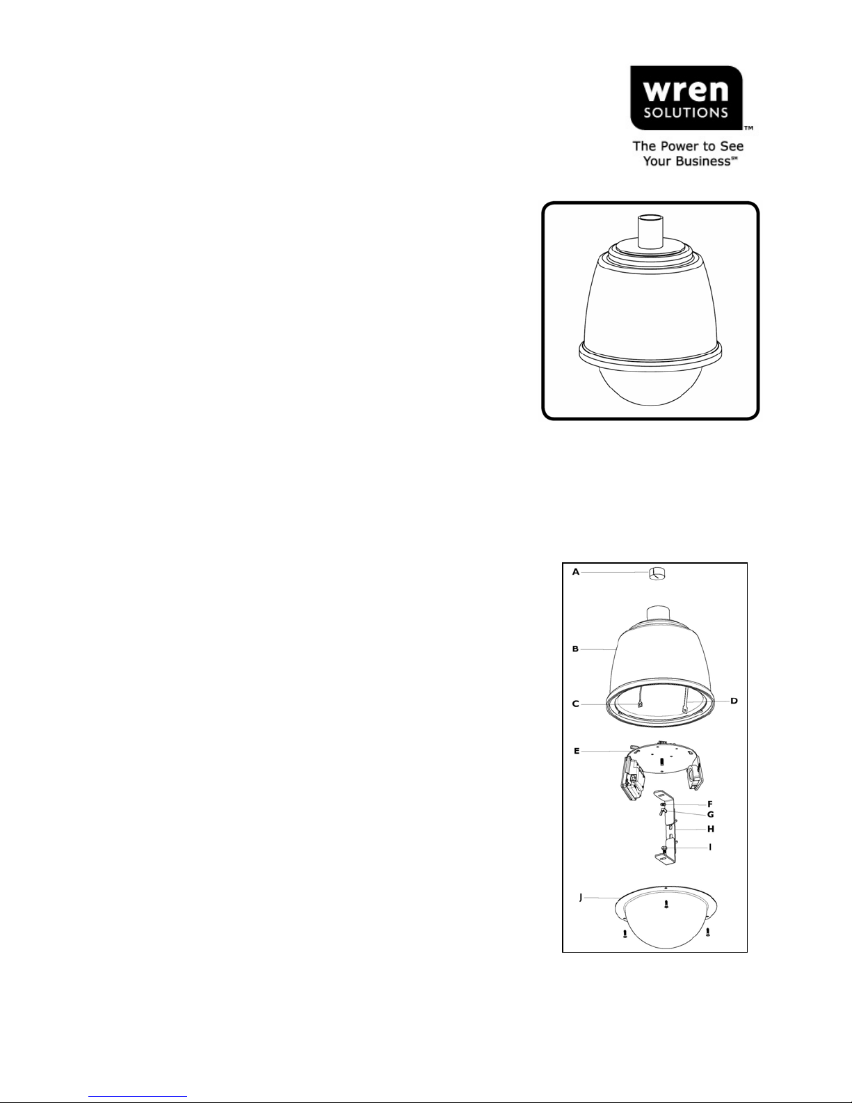
A. Foam Dust Plug
B. Housing (double wall)
C. Mounting Plate safety Tether
D. Dome Safety Tether
E. Camera Mounting Plate Assembly (with optional
heater/blower and circuit board)
F. Flat Washer
G. Wing Nut
H. Multi-position Camera Bracket
I. Camera Bolt
J. 8” Dome Assembly
Warnings and Safeguards
Prior to installation and use of this product, please observe the following
warnings
1. Installation and servicing should be performed by qualified personnel
only.
2. All work should conform to local building codes.
3. Use only Wren-approved replacement parts or supplied accessories.
Failure to comply may invalidate remaining warranty period.
4. Verify proper location and installation of the housing mount (1½” NPT
pipe or approved mount). The pipe or mount shall be capable of
supporting three (3) times the weight of the housing and its contents.
5. Verify proper installation of cabling to support camera power and
communication requirements for fixed camera applications.
6. The EG8 is designed to be operated by a 24VAC power source
capable of supplying 2 amps continuously, plus required amperage for
the selected camera(s). (See Master Power Supply instructions for
wiring/installation instructions of Master Power Supply.)
PROPERTY OF WREN Page 1 of 3 7L240rev-C 12/19/2006
124 WREN PARKWAY • JEFFERSON CITY, MO 65109 • TOLL FREE (800) 881-2249 • FAX (877) 893-2317
www.wrensolutions.com
OUTDOOR IP SOLUTIONS:
EG8-IP
8” Environmental Globe
Figure 1
Page 2
Preparation
1. Carefully unpack box and verify that all components listed are
included. [Figure 1]
2. Remove the dome assembly by loosening the three (3) screws. If
desired, the tether may be disconnected by backing out the screw in
the center of the retaining rivet. Take care when handling the dome
to prevent scratches or other damage.
3. Remove the camera mounting plate by loosening the two screws in
the keyhole slots with a screwdriver, then loosening and removing
the third screw. Rotate the plate slightly so that the keyhole slots
are aligned with the heads of the screws and disconnect from the
wire tether to remove the plate.
Installation
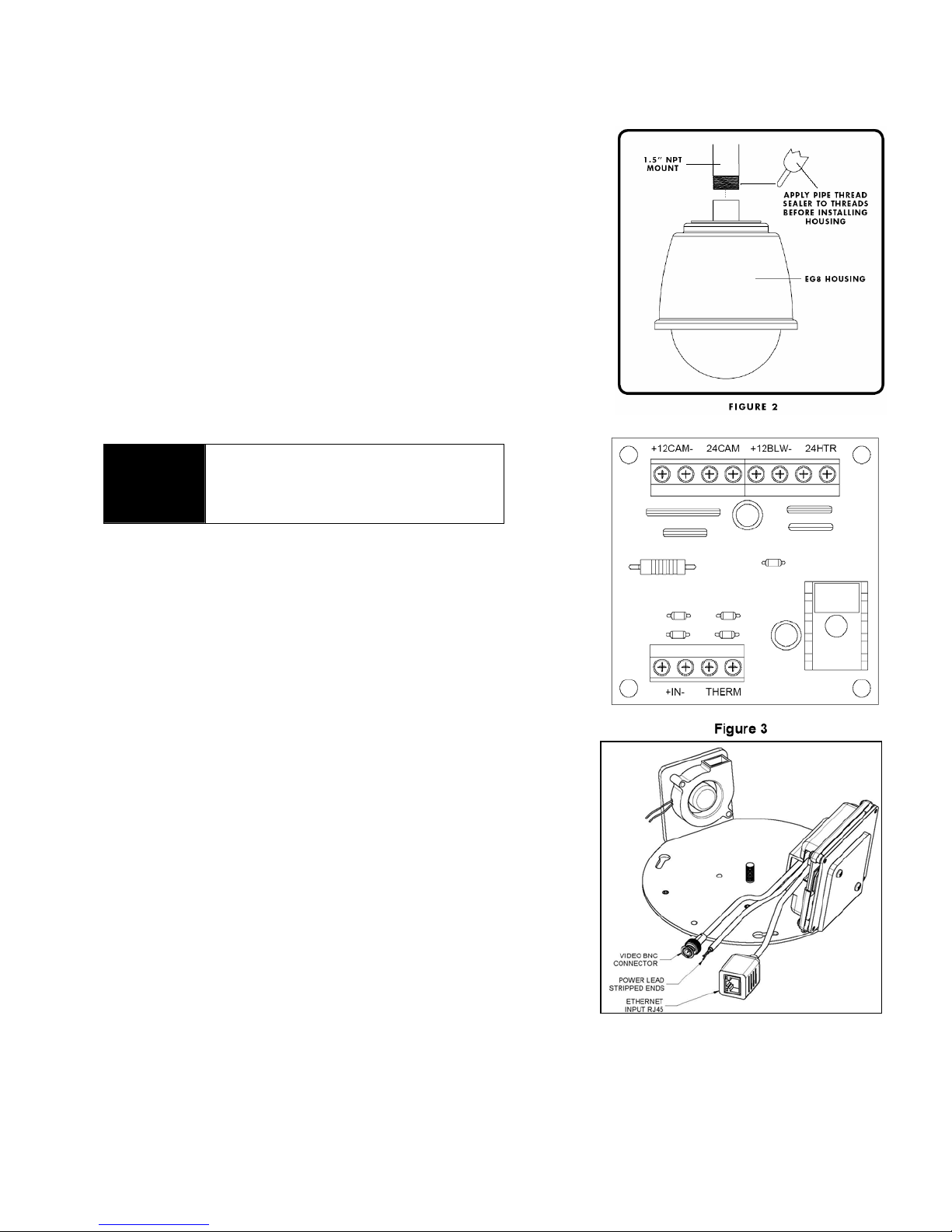
1. Apply thread sealant (included) to the 1½” NPT pipe threads or
approved mount. This procedure will prevent moisture ingress
through the threads. [Figure 2]
Failure to properly seal the 1½” NPT
WARNING
pipe threads will permit water to
enter the housing and may damage
the internal equipment.
2. Install EG8 assembly on 1½” NPT pipe or mount by rotating
counter-clockwise until threads are fully engaged.
3. Remove foam dust cap and route Cat5 and power cables into the
housing.
4. Reconnect the mounting plate’s wire tether and allow mounting
plate to be suspended by tether.
5. Connect 24VAC to the input terminals on circuit board marked
“+IN-“. [Figure 3]
6. Push extra wire length up through housing flange and re-install the
foam dust cap in the cable entrance of the housing.
7. Route wires carefully over the edge of the mounting plate, taking
care to ensure that the BNC (shown in Figure 4) and camera
power leads (connected to the “24CAM” output on the circuit
board) will be accessible in the following step. Re-install and
tighten the screws holding the camera mounting plate.
8. Insert end of Cat5 into the RJ45 jack in the housing. [Figure 4]
9. Mount camera to bracket and make the following connections:
a. Connect the BNC (see Figure 4) to the video output jack
of the camera.
b. Connect the 24VAC power leads from the circuit board
terminals marked “24CAM” to the camera power input.
10. Aim and focus camera as desired.
11. Re-attach the dome tether by pushing the rivet into the hole and
turning the screw fully in (do not over-tighten). Re-install dome
assembly and tighten screws to ensure a proper seal with the
dome gasket.
PROPERTY OF WREN Page 2 of 3 7L240rev-C 12/19/2006
124 WREN PARKWAY • JEFFERSON CITY, MO 65109 • TOLL FREE (800) 881-2249 • FAX (877) 893-2317
www.wrensolutions.com
Figure 4
Page 3
Electrical Properties
• Input Voltage = 24VAC +/- 10%
• Power = 2.0A @ 24VAC (heater on, not including
camera)
• Blower 4.7 CFM @ 2.2 watts (continuous
operation)
• Heater 40 watt heater
Optional Mounts (consult factory for color and style
options)
• Curved Wall Mount HM11xx
• Pole Mount HM12xx
• Corner Mount HM13xx
• Roof (Parapet) Mount HM14xx
All Products Are Subject to the Current Version of Wren Terms and Conditions
WARRANTY INFORMATION
Wren warrants EG8-IP for five (5) years for the housing
and one (1) year for the electronics from the purchase
date, recorded as the ship date on Wren’s invoice,
against any defects in material or workmanship as long
as the product is used for the purposes for which it was
intended. Warranty claims will be processed only when
accompanied by original order numbers which include:
purchase order number, sales order number, invoice
number and serial number (if applicable).
RETURNS
In order to return parts to the factory for repair or credit, please call the factory at
(800) 881-2249 or (573) 893-2249 to obtain a Return Authorization (RA) number.
All returns are subject to Wren’s RA Policy. Goods returned for credit should be
in their original condition—new and unused. All merchandise returned by the buyer
for credit, and accepted by Wren, may be subject to a 20% restocking charge.
Products returned within 31-90 calendar days from the purchase date will be
subject to a 20% restocking fee. Products may not be returned more than 90
calendar days from the purchase date. Custom, special order and OEM products
may not be returned.
Wren®, the Wren logo, The Power to See Your Business, Wren IP Solutions, No Tools Required and Solution Set Series are trademarks of Wren. The trademarks that are followed by ® are
registered trademarks in the U.S. All other trademarks and/or registered trademarks mentioned herein are properties of their respective owners and are used for reference purposes only.
The use of these trademarks does not indicate any affiliation with or sponsorship of or by Wren. ©2006 Wren. All rights reserved.
PROPERTY OF WREN Page 3 of 3 7L240rev-C 12/19/2006
124 WREN PARKWAY • JEFFERSON CITY, MO 65109 • TOLL FREE (800) 881-2249 • FAX (877) 893-2317
www.wrensolutions.com
 Loading...