

Wren KLW4000N Series, KLW4000SHNP Series, KLW4100 Series, KLW4000HNP Series, KLW4000A Operation And Maintenance Manual
...
KLW4000
Operation And Maintenance Manual
Of KLW4000 Series Hydraulic Pump
.
1.When using, do not permit any person stand at the oil output in order to avoid personal injury and
equipment damage. Please put the pump far away from the fire.
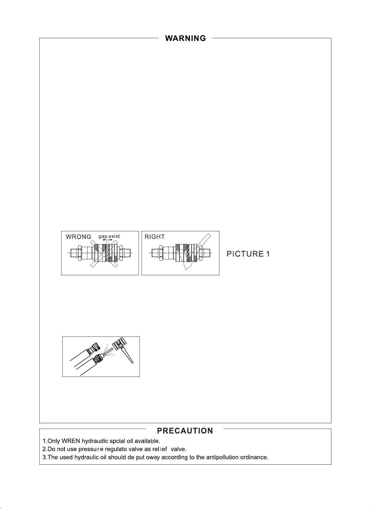
2.Make sure that the hose and quick coupler be connected before building up the pressure in order to
avoid hydraulic fluid spurting out to cause personal injury.
3.The maximum operating pressure of this pump is 70Mpa(10,000Psi),WREN has set up the pressure to
70Mpa before selling this pump. Please do not adjust to a pressure higher than the maximum pressure
whichWREN has not set.
4.If this pump is used for operating other equipments, make sure the maximum operating pressure of the
equipments will be less than 70Mpa. Please adjust the pressure to which the equipment need, or else the
equipment would be damaged.(Referrence content 5)
5.Make sure the power of the pump is shut off before repairing it.
6.Please shut off the switch before starting power; if the switch is on, the pressure may increase.
7.Make sure the equipment be connected with ground to avoid electric shock.
8.Do not start the pump without oil in tank.
9.Please do not change any part of the pump; if it must be changed, please inform WREN or Wren's agent
for help. Without allowance of WREN or its agent, any refit of it will be out of our warranty Range.
10.Please do not fill the pump reservoir with too much oil, otherwise, the pressure of the reservoir will
increase and the oil will spill over, so the reservoir will be broken and the environment will be polluted.
11.When the pump works,the pressure may be increased with the returning oil.If the oil filler cop is opened
at the moment, this may cause the injury.
12.Make sure the quick coupler is tightened; if the quick coupler is not tightened enough, the equipment
will not work normally; if it is a synchronic system, the problem may cause one or several pieces of
equipment out of order and the quick coupler may be broken and it may cause personal injury or equipment
damage.
13.Make sure to reep the pump in cleaning.
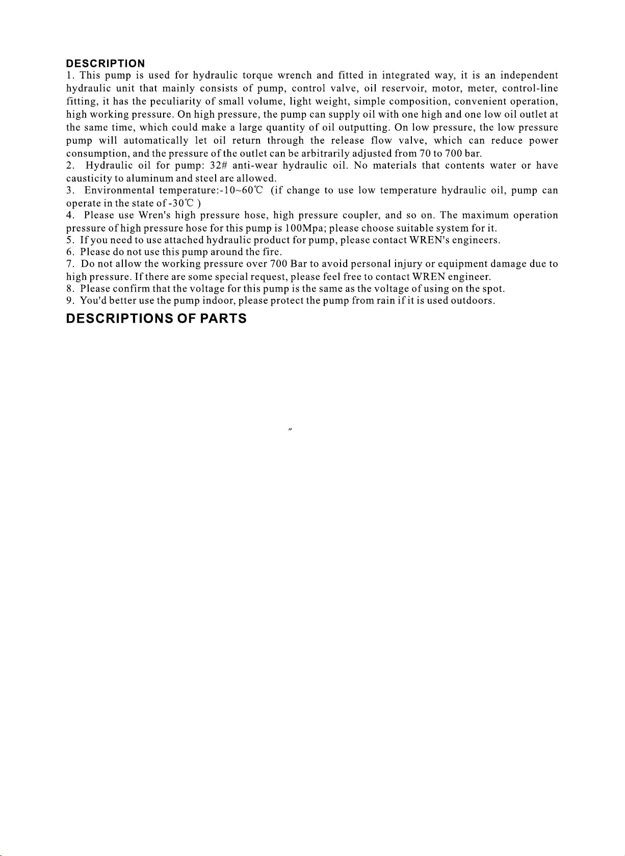
14.Please stand away from the position where the hydraulic oil may be spurt out; hydraulic
oil may penetrate your hand and hurt you.
15.If the hydraulic oil splashed in your eyes, please immediately wash your eyes about 15
minutes with clean water, then you must go to hospital for help right now.
PICTURE 2
16.Please do not touch the pressurized hose; if the hydraulic oil splashed out, it will cause serious
injury.
17.Hydraulic hose is easily spoiled fitting; you inspect the hose with eyes regularly and find no problems,
but the inner side may have crack and small hole; WREN suggests you should change the hose regularly
for smoothing use.When using,try to avoid bending the hose in sudden.
11
1. Oil reservoir: To store hydraulic oil, make sure the reservoir enough oil to keep the pump work
normally.
2.The adjusting pressure regulator: Adjust this valve for setting the working pressure of power pack
(the)max working pressure has been locked before sales, please do not change the locked pressure
at any time.
3. Pressure gauge: it’s effects 0-100Mpa, showing the working pressure of the power pack.
4. Frame for protecting: it is fixed on motor for carrying conveniently.
5. Motor: provide power.
6. Radiator: to exclude the heat, ensure the operating time and life of the pump.
7. Oil level measurer: it can help us know the oil level, when the oil less than the1/3 of total, please
Fill the especial oil for hydraulic tools of WREN.
8. Release oil port: G1/4.
9. Control system: the integrated electric equipment of the pump.
10. Cover plate for oil tank: seal the oil tank and install the parts of power pack.
11. Solenoid valve: Its function is output oil when the pressure is very high, control the flow when
return oil, and soon. It can be set up the maximum pressure and protect system to work normally at the
pressure set up. The threads of oil output port is NPT1/4”.
12. Quick coupler : it’s function is output oil when the pressure is very high, control the flow when
return oil , and so on, it can be set up the maximum pressure and protect system to work normally at
the pressure set up, the threads of oil output port is NPT 1/4”
13. Valve block: control oil driving in and out; make sure the hydraulic system can be worked normally
under the pressure to be set up.
14. Oil filling port: To be used for filling and replacing oil.
2
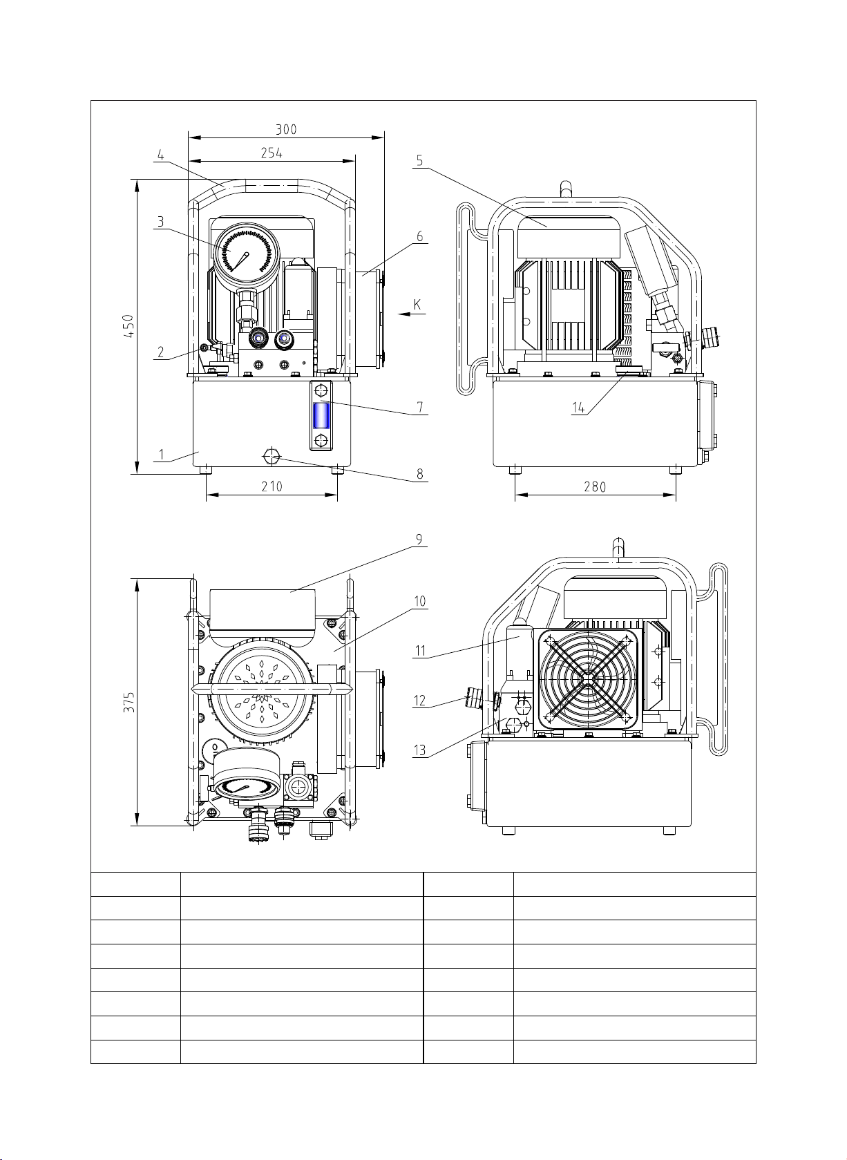
EXTERNAL DIMENSION AND DESCRIPT ION OF PARTS
Item Description Item Description
1 8
2 9
Adjusting pressure regulator
3 10
4 11
5 12
6 13
7 14
Oil reservoir
Pressure gauge
Frame for protecting
Motor
Radiator
Oil lever measurer
3
Release oil port
control system
Cover plate for oil tank
Solenoid valve
Quick Coupler
Valve block
Oil filling port
0.8
7
200-240
/200-240V 60HZ 0.9KW /100-130V 60HZ 0.9KW
27
,And cover on the dust cap.
4
1.Ready:
1.1 KLW4000hydraulic power pump is designed for hydraulic torque wrench. There is a 2-way, 4position solenoid operated direction control valve on the pump, port A is high pressure point, it can
export the oil at the high pressure, and port B is low pressure point which can output the oil at the
low pressure.
1.2 Please loosen the high-pressure valve for adjusting pressure before operating.
Adj ust
pre ssure
2.Adjust the pressure:
2.1 Please connect the power and push the switch at the position of “ON”. Then press the lock
button make the power pack working, then the power pack will output the low-pressure.
2.2 Please press the retract button on the controller and adjust the pressure unit the working
Plessure reach to what you need, and then loosen the retract button on the controller.
Lock butt on
Retra ct b ut to n
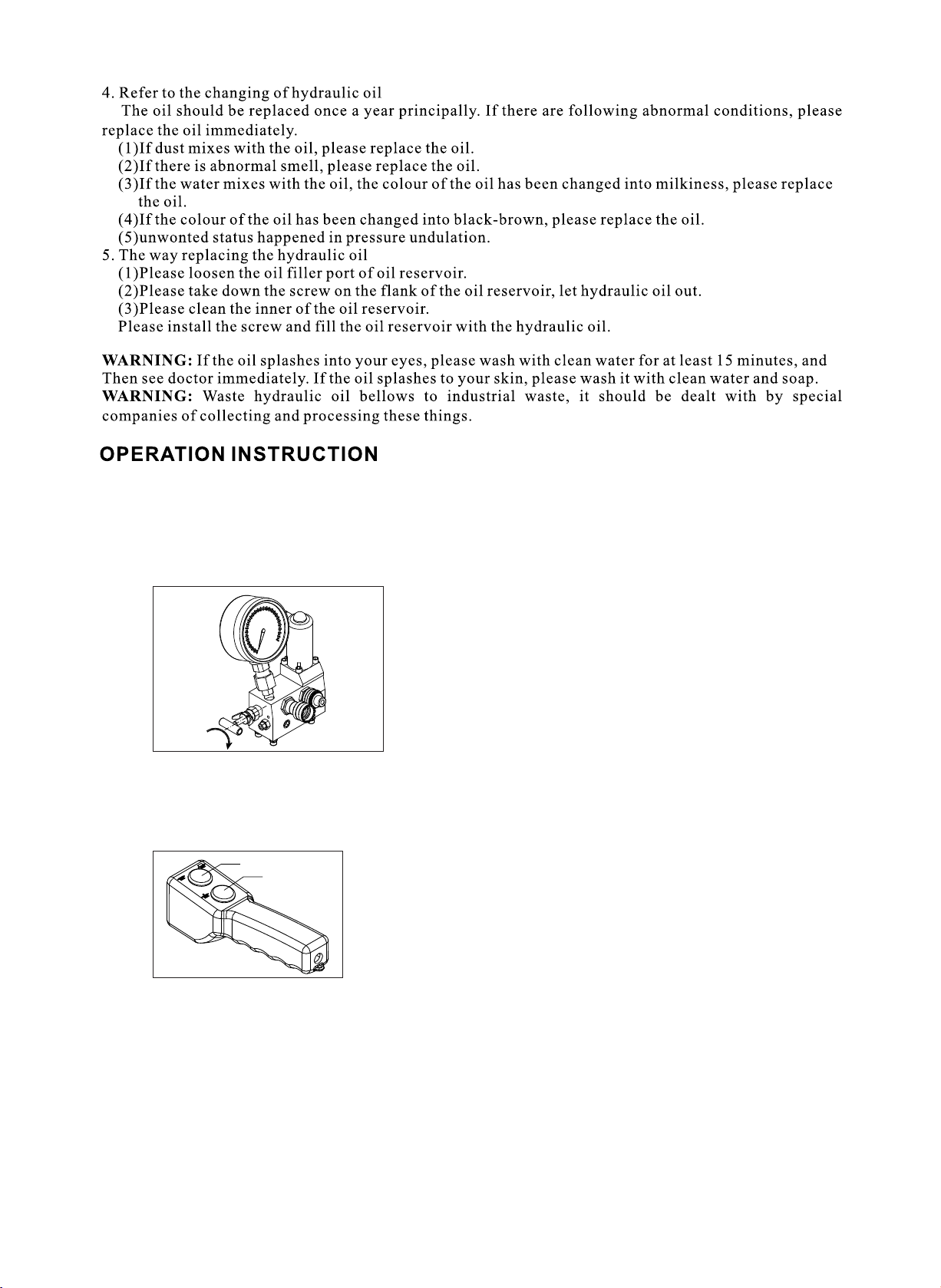
3. Operation:
3.1 Please press down the retract button on the controller, the pump output. The high pressure,
torque wrench works;Loosen from the retract button, the pump output the low pressure, the
torque wrench retracts; press down the lock button, the button retracts, the pump stops.
3.2 After operating, please turn off the power. Then press the rubber button on the top of solenoid
operated direction control valve in order to release the pressure in hoses and equipments,then you
can take down the hose and cover the safety cap for the quick couplers.
Attention: First time to use or after service, please try several time to operate without any
loading, this ca eliminate the in system.
5
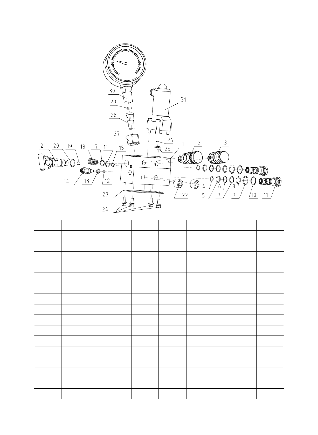
PART LIST FORVALVE SYSTEM
ITEM
1
2
3
4
5
6
7
8
9
10
11
12
13
14
DESCRIPTION QTY
Valve block
Female coupler
Male coupler
O-ring O-ring
O-ring
Retaining ring
Retaining ring
O-ring
O-ring O-ring
Retaining ring
Reversing valve
O-ring
O-ring O-ring
Adjusting valve
1 17 1
1
1
2
2
2
2
2
2
2
2
1
1
1
ITEM
18
19
20
21
22
23
24
25
26
27
28
29
30
DESCRIPTION QTY
Retaining ring
Unilateralism valve
O-ring
Adjusting valve
Casing screw
O-ring
Screw
O-ring
Connector
Connector
Gauge
1
1
1
1
2
1
4
2
1
1
1
1
1
15
16
O-ring
O-ring
1 31 1
1
6
Solenoid valve
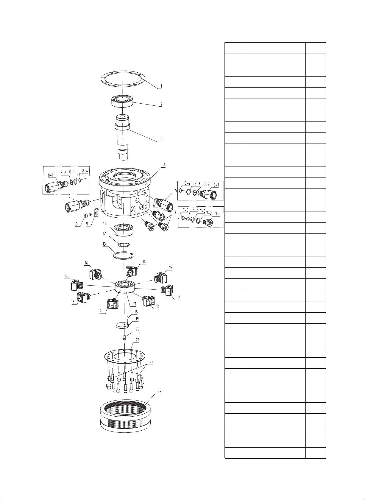
PART LIST FOR PUMP HEAD
ltem
Description
QTY
1
2
3
4
5
5-1
5-2
5-3
5-4
6
7
7-1
7-2
7-3
7-4
7-5
8
Seal gasket
Bearing
Bearing pole
Pump head
Release valve
Relief Valve
Retaining ring
Safety valve
Unilateralism valve
Check Valve
Retaining ring
Retaining ring
Release valve 2
O-ring
O-ring
O-ring
O-ring
1
1
1
1
1
1/set
1/set
1/set
1/set
1
2
1/set
1/set
1/set
1/set
1/set
1
8-1
8-2
8-3
8-4
9
10
11
12
13
14
15
16
17
18
19
20
Relief Valve
Retaining ring
Bearing
Metal Retaining Ring
Piston 1
Piston 2
Piston 3
Bearing
O-ring
O-ring
Clip
Screw
Circle
Pin
Plate
Screw
1/set
1/set
1/set
1/set
1
1
1
1
1
4
2
2
1
1
1
1
Connecting plate
21
22
23
7
Screw
Filter
1
16
1

TROUBLE SHOOTING GUIDE OF HYDRAULIC PUMP
Mal function Reason for caused malfunction Solution
The pump can not be started
The system has no pressure
The system has no pressure
after reinstall the couplers
Leaking in the couplers
The system pressure can
not reach to the rated
pressure
Un-suitable power source
The power is not connected
The coupler is not connected
properly
No oil in the tank Fill oil
Not enough oil
Check if flow control valve, singledirection valve in the system is open
The couplers is not connected in
the properly position
The o-ring, retaining ring worn
out in the couplers
The pressure for high-pressure
leaking valve is adjusted too low
Oil is mixed with water
Ball steel in pressure relief valve
may be broken or the valve seat
may be frayed
Air may be sucked into the system
The leaking valve may be frayed
Confirm if the power meets pump’s
need
Check the power
Re-install
Fill oil
Open the flow control valve to ensure
the system is connected
Uninstall the couplers, check if the steel
roll is elastic with a rod, if it can not move
please knock it with hammer to elimina
te the mist hydraulic oil.
Replace the couplers
Please check the gauge, adjust it to
rated value
Replace the oil, please
Replace them,please
Repeat operating the system with no
load for several times to eliminate air
Replace it, please
There is a strong noise
when the power pack is
operated
When using under static
pressure, the pressure
reduces slowly
High-pressure flux is not
enough
High-pressure leaking valve may
not be tightened
The o-ring for high-pressure leaking
valve may be broken
There may be some inclusion into
the oil
The bearing may be broken
Air may be mixed into this power
pack
The seal is out of control,please
check all the seal
Piston or spring may be broken
Leaking may be happened at
brushfire position
Oil lever may be too low
High-pressure system may not
eliminate the oil fully
Too low oil temperature may make
lead to suck oil difficultly
Oil temperature may be too high
that cause the damage of pump
Tighten it, please
Replace it, please
Wash the power pack valve and
replace oil
Replace it, please
Exhaust the air from the system
Replace the seal
Change them, please
Tighten the couplers and replace
the seals
Fill the oil,please
Please try several times without load
before using
Control the temperature at -10℃ to
60℃ ,please
If so, the power pack need to be
replaced with new one
8
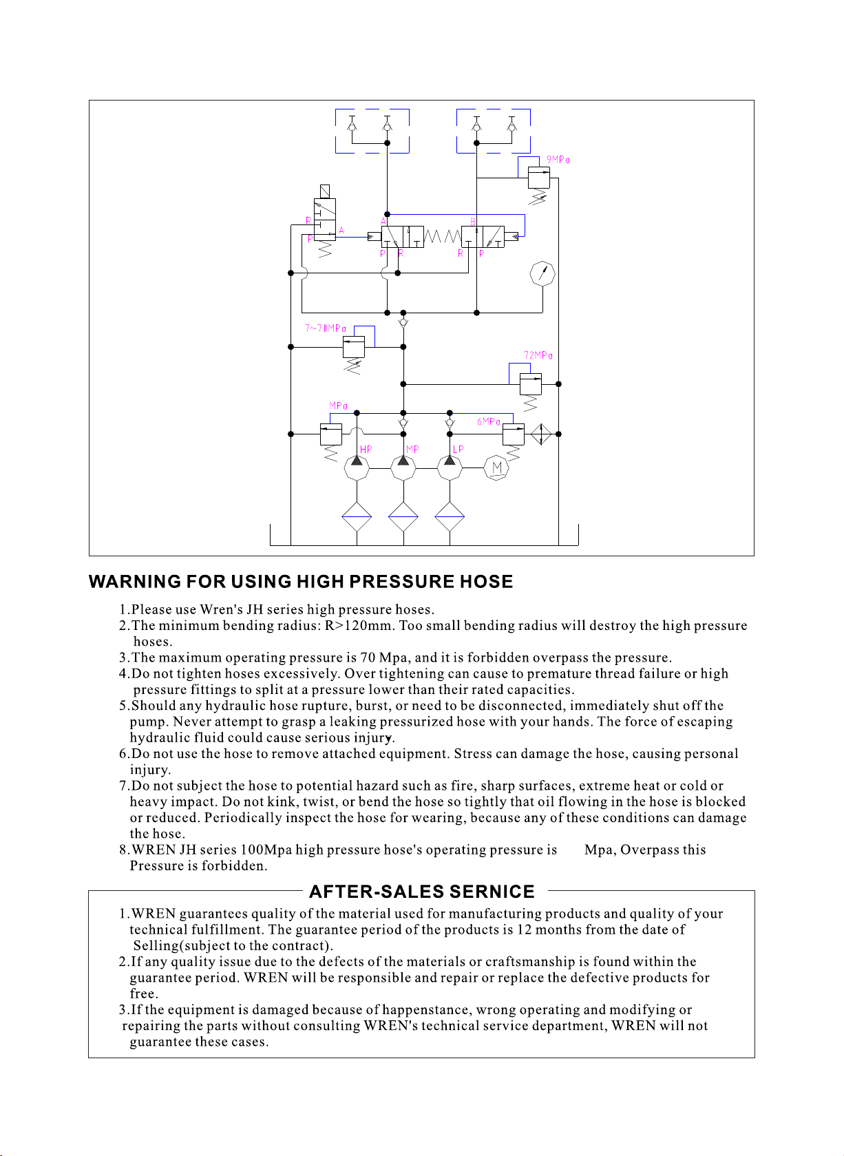
HYDRAULIC PRINCIPLE
24~26
70
9
 Loading...