


S and H Serises
Hydraulic Torque Wrench
Operation Manual
Hangzhou WREN Hydraulic Equipment Manufacturing Co.Ltd
Add:No 24 xingxing Road, Xingqiao, Yuhang district, Hangzhou, China
TEL: 0571-88110295 FAX:0571-88110210
PC:311100
Http://www.wrenchina.com
EMAIL:info@wrenchina.com
W214
The original version of the Chinese Translation

Catalog
Important Receiving Instructions …………………………………1
S Series,Square Drive Torque Wrenches
H Series,LOW Profile Torque Wrenches
Waring And Caution
Operating The Wrench
S Series Hydraulic Torque Wrench Pressure-Torque Chart
S Series Hydraulic Torque Wrench Pressure-Torque Chart
H Series Hydraulic Torque Wrench Pressure-Torque Chart
H Series Hydraulic Torque Wrench Pressure-Torque Chart
Inspect、Repair And Maintain
EC Declaration Of Conformity
Bolting Tightening Force Recommented Chart
…………………………………1
…………………………………2
…………………………………………2
…………………………4
…………………………………………5
…………9
…………10
…………11
…………12
………………………………………13
……………………………6 8
Operation
………………………………………18
………………………………………14 17
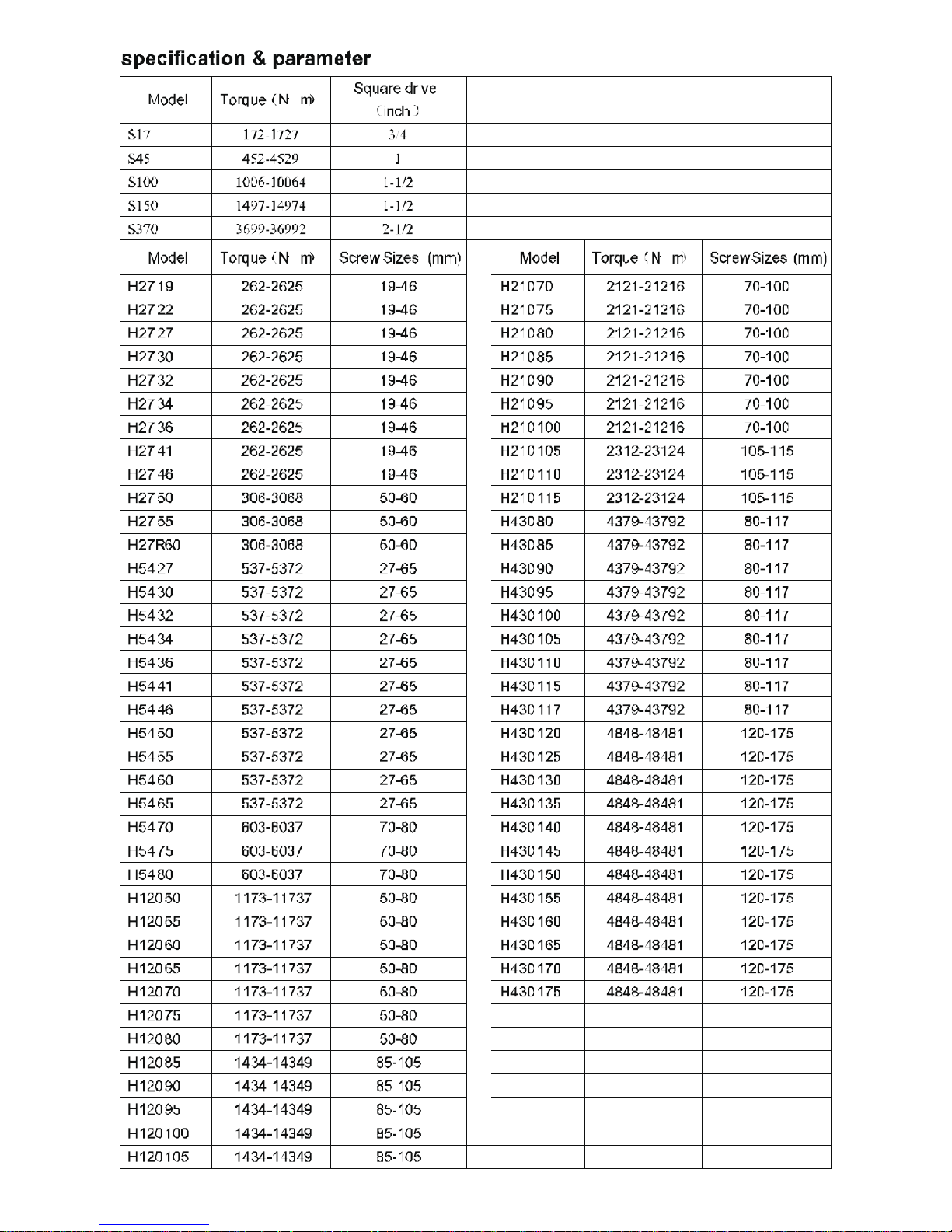
Specification & Parameter
Waring Plate
…………………………………………3
~
~
OPERATION AND MAINTENANCE MANUAL
FOR S AND H HYDRAULIC TORQUE WRENCHES
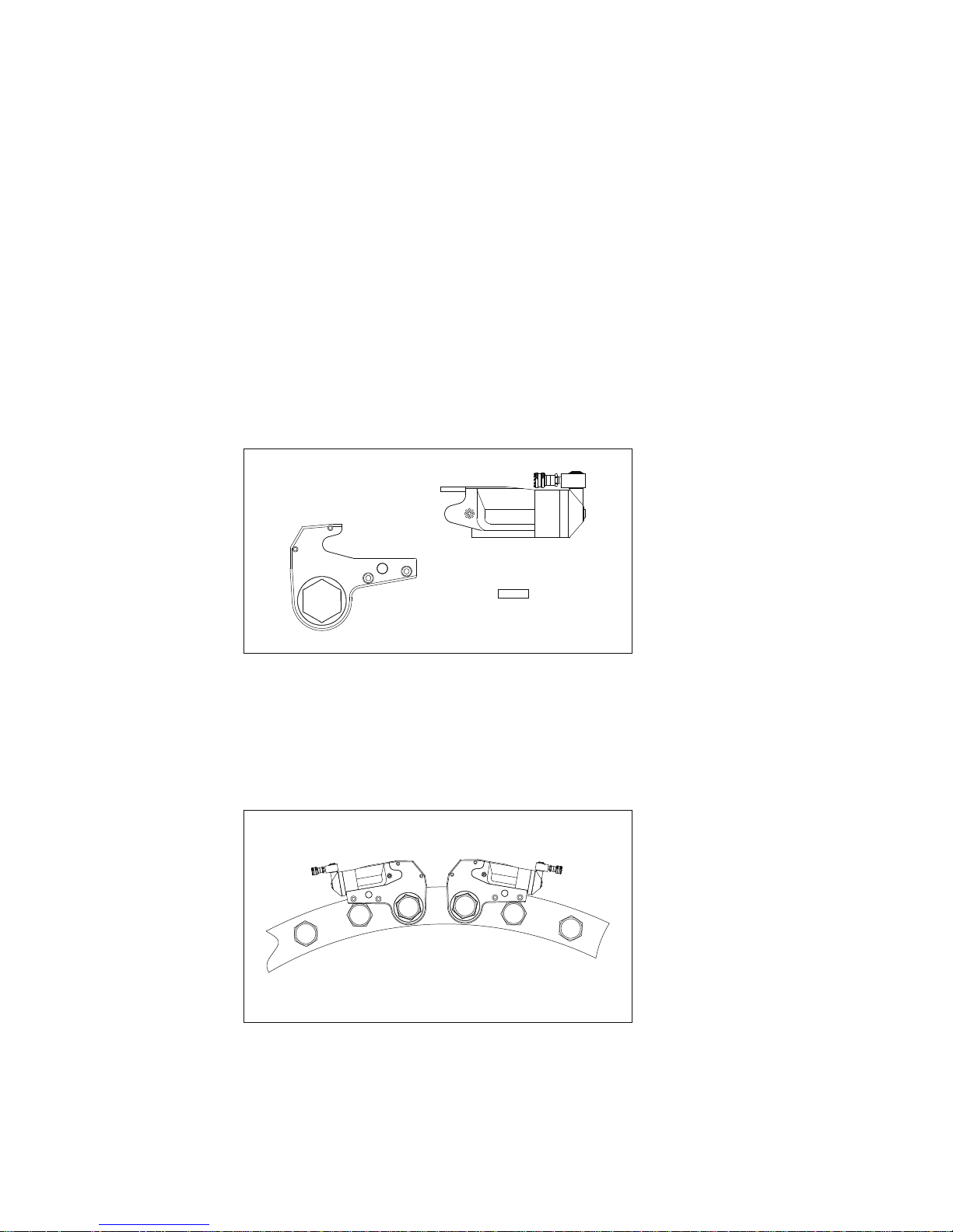
IMPORTANT RECEIVING INSTRUCTIONS
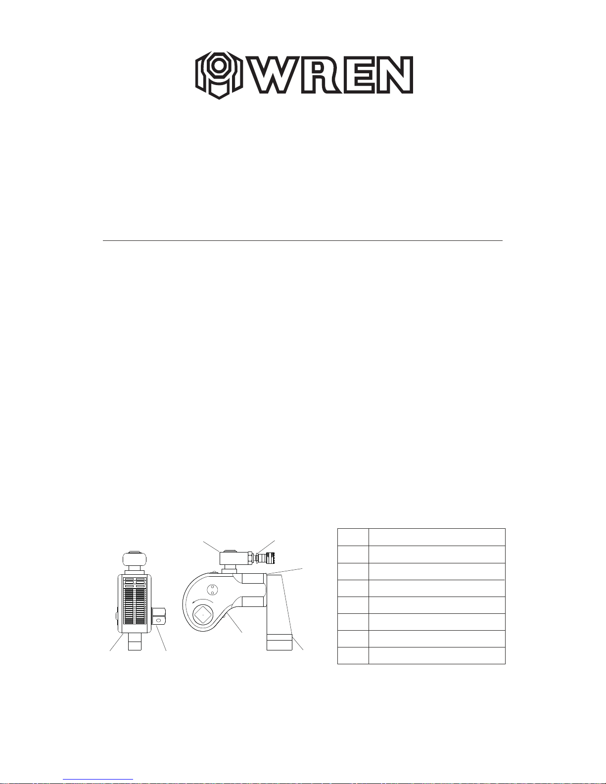
①
②
③
④
⑤
⑥
⑦
ITEM
BODY
360°SWIVEL JOINT
QUICK COUPLING
FIXING HOOK
360° SWIVEL REACTION ARM
SQUARE DRIVE
DRIVE RETAINER
NAME
SAFTY FIRST !!
Please read carefully follow instructions, warning and caution. Please observe the safety
precautions so that it can avoid personal and equipment to injury when you operate the
equipment. WREN is not responsible for any damage resulting from the operation of
irregularity.
Carefully inspect all components for shipping damage. If any shipping damage is found,
please notify carrier at once. Shipping damage is not covered by warranty. The carrier is
responsible for all repair or replacement cost resulting from damage in shipment.
The material of S series and H series Hydraulic Torque Wrenchs are Aluminium-Titanium
alloy and superhigh strength alloy steel for increased strength, intensity and durability of
the tool. High repeatability, a precise design is with accuracy ±3%.
DESCRIPTION
S series, Square Drive Torque Wrenches:
It is operating manual of S series and H series wrenches, please read carefully follow
instructions﹑warnings and cautions before using the tools.
①
② ③
④
⑤
⑥⑦
1
2
Do not use wo rn sock et and squ a re dr i ve.
WARNING AND CAUTION
WARNING
WARNING
WARNING
CAUTION
CAUTION
WARNING
CAUTION
CAUTION
CAUTION
To avoid perso na l i njury and e qu ipment damages, be sure t hat every hydrauli c compone nt
can ra ted fo r 10,00 0PSI ( 700kg /cm²) Ope rati ng Pressu re.
Try to minim um the dang e r of over l oad Us ing hyd ra ul ic gauge to indicat e the workin g
pressure. Hy draulic gauge is a win dow to show what happened in t he hyd raulic syst em.
To replace t he wor n components w ith the WRE N new components as soon as possib le.
Do not subje c t th e components to potentia l ha zar d s uch as fir e, sharp surfaces,
extreme
heat or cold, or hea ve im pa ct.
Neve r attempt to grasp a leaking p r es surize d hose with your hands. The force of es ca ping
hydrauli c fluid cou ld cause serious in jury.
Do not let the ho se kink, twist, curl or bend s o ti gh tly that oil flo w withi n the hose is blo cked
or reduced.Do not us e th e ho se to move att ac h ed equipment. Stress ca n damage the hose,
causing
personal inj ury.
To avoid pe rs onal inju ries and equip me nt d am ag es , do not remov e the shroud of the
wrench .
Do not modify an y com ponent of t h e wre n ch. Do not change the re lief valv e which
i
the swivel couplings.s in side
Th e incorrect system connecti on w ill cause failu re and danger. Before connecti on, m ake
sure th e swivel cou pling s being cle an. After appli catio n, the swivel cou plings mu st be put
on
the dust caps.
Please use the socket of good perf or mance . The qualit y sho uld be acco rd ing with the
stan dard of ISO -2 72 5 or ISO-1174 or DIN3 12 9 or DIN3 12 1 or ASM E-B1 07 .2/1995.
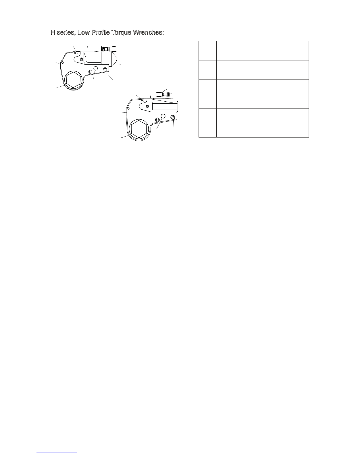
H series, Low Profile Torque Wrenches:
ITEM
NA ME
①
②
③
④
⑤
⑥
⑧
⑦
LOW PROFILE CASSETTE
PIN
POWER HEAD
QUICK COUPLING
REACTION ARM
LINK PIN
RATCHET
360°×360° SWIVEL JOINT
⑨
360°SWIVEL J OINT
①
② ③ ④
⑤
⑥
⑧
⑦
H27/H54/H120/H210
①
②
③
④
⑨
⑥
⑧
⑦
H430
3
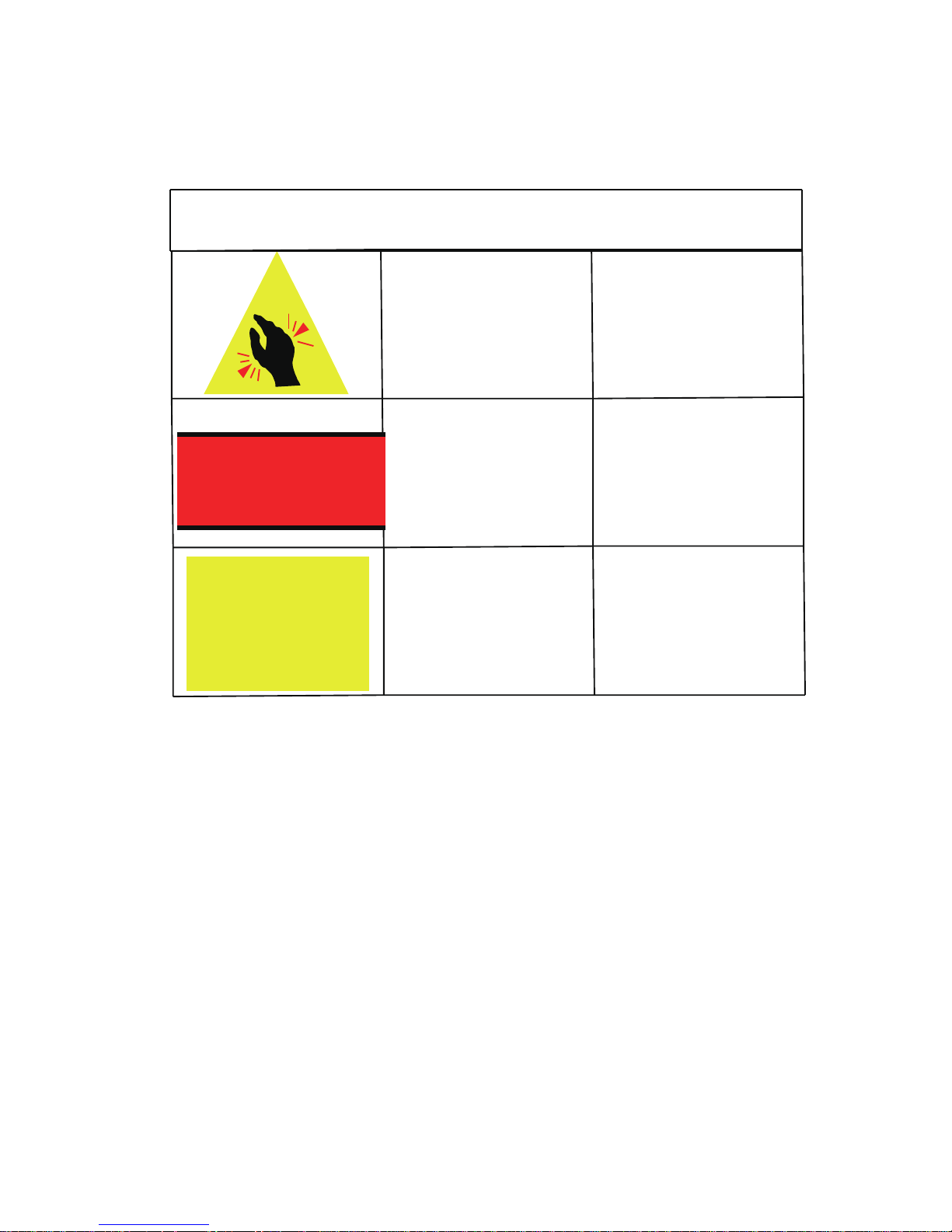
Warning Plate
Warning plate is shown in table 1
IF DRIVE STICKS OUT RIGHT,
IT'S SET FOR TIGHTEN.
LEFT. IT'S SET FOR LOOSE!
LOCK REACTION
ARM BEFORE
USING TOOL!
war ning table
Meaning
Affix ed Position
IF DRIVE STICKS OUT
RIGHT IT’S SET FOR
TIGHTEN.LEFT IT’S SET
FOR LOOSE!
WORK HEAD
REVERSE LEVER
NO HAND
LOCK REACTION ARM
BEFORE USING TOOL!
REVERSE LEVER

4
Bo l ting
FOR M 1
NOTE:
BOLT ING TIGHTE NING FORCE RECOM ME N TED CH ART
St rengt h Grad e
4.8 6.8 8.8 10. 9
Min bre aking
st rengt h
3 92MPa 588MPa 78 4MPa 94 1MP a
Material
Q2 35 (SS 41) 35(S35C) 35CrMo(SCM3) 42CrMo(SCM4)
Thre ad KGM N .m
22 7 69 10 98 14 137 17 165
24 10 98 14 137 21 206 25 247
27 14 137 21 206 29 284 35 341
30 18 176 28 296 41 402 58 569
32 23 225 34 333 55 539 78 765
36 32 314 48 470 70 686 100 981
41 45 441 65 637 105 1029 150 1472
46 60 588 90 882 125 1225 200 1962
50 75 735 115 1127 150 1470 210 2060
55 100 980 150 1470 180 1764 250 2453
60 120 1176 180 1764 220 2156 300 2943
65 155 1519 240 2352 280 2744 390 3826
70 180 1764 280 2744 320 3136 450 4415
75 230 2254 350 3430 400 3920 570 5592
80 280 2744 420 4116 480 4704 670 6573
85 360 3528 530 5149 610 5978 860 8437
90 410 4018 610 5978 790 7742 1100 10791
95 510 4998 760 7448 900 8820
100 580 5684 870 8526 1100 10780
105 660 6468 1000 9800 1290 12642
110 750 7350 1100 10780 1500 14701
115 830 8143 1250 12250 1850 18130
120 900 8820 1400 13720 2250 22050
130 1080 10584 1650 16170 2500 24500
145 1400 13720 2050 20090
155 1670 16366 2550 24990
175 2030 19894 3050 29890
mm
Th e belows are DIN(F or you referen ce)
KGM N .m KGM N .m KGM N .m
The figure of the chart is the Max torque of the bolting, the recommended torque is 80% of chart
figure For instance:M52,strength grade is 8.8,the torque is 4704×80%=3763N.m
12. 9
117 6MPa
40 GrNiMoA(SNCM)
23 225
36 363
49 480
69 680
93 911
120 1176
180 1764
240 2352
250 2450
300 2940
370 3626
470 4606
550 5390
680 6664
850 8330
1050 10290
1350 13230
KGM N .m
14
16
18
20
22
24
27
30
33
36
39
42
45
48
52
56
60
64
68
72
76
80
85
90
100
110
120
M
5
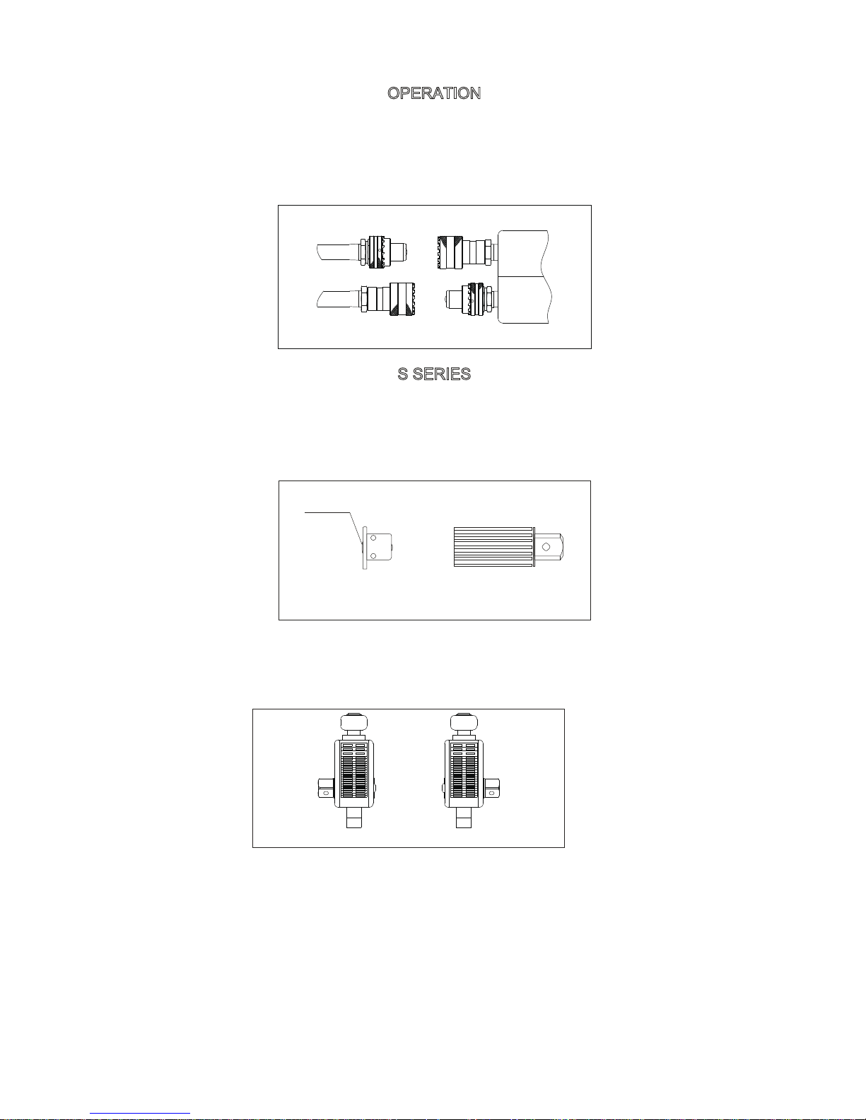
OPERATION
The wrench and power pump are connected by a 700 BAR operating pressure, twin-line hose
assembly. Each end of the hose will have one male and one female connector to assure proper
interconnection between pump and wrench.
CONNECTING THE TOOL
FIG3
S SERIES
DRIVE DIRECTION CHANGE
To remove the square, disengage the drive retainer assembly by depressing the center round
button and gently pulling on the square end of the square drive. The square drive will slide easily
out.
To insert the drive in the tool, place the drive in the desired direction, engage drive and bushing
splines, then twist drive and bushing until ratchet spline can be engaged. Push drive through
ratchet. Depress drive retainer button, engage retainer with drive and release button to lock.
SETTING THE REACTION ARM
All WREN's Torque wrenches are equipped with a universal reaction arm. These reaction arms
are employed to absorb and counteract forces created as the unit operates. The reaction arm
should extend in the same direction of the square drive; However, slight adjustments may be
made to suit your particular application. The function of a reaction device is to hold the tool in
position against the forces generated to tighten or loosen bolts or nuts. Hydraulic wrenches
generate tremendous force. The reaction arm can be
Squ are Dri ve
Drive Retai ner
Button
FIG4
FIG5
lossing tightening

6
positioned in numerous places within a 3600 circle. However, for the arm to be correctly
positioned, it must be set within a 900 quadrant of that circle. That quadrant is the area
located between the protruding square drive and the bottom of the housing away from the
swivel inlets. It will always be toward the lower half of the housing and on one side of the
housing when tightening and the other side when loosening.
SETTING THE SQUARE DRIVE FOR ROTATION
The position of the square drive when looking toward the shroud will determine if the tool
is set to tighten or loosen the nut. When the square drive extends to the left when looking
at the shroud with the inlets away from you, the tool is set to loosen the nut. When the
square drive extends to the right, the tool is set to tighten the nut. To change the direction
of rotation for MXTA series wrenches simply push the square drive into the housing until
the drive projects out the opposite side of the tool.
SETTING THE TORQUE
After determining the desired torque, use the torque conversion charts on page 5 to
determine the pressure that is necessary to achieve that torque.
1.Connect the tool to the power supply and turn the pump on.
2.Depress the advance remote control button causing the pressure to be shown on the
gauge.
3.Adjust the pressure by first loosing the nut that locks the pressure adjustment handle and
then rotate the handle clockwise to increase the pressure and counter clockwise to
decrease the pressure. When decreasing pressure, always lower the pressure below the
desired point and then bring the pressure gauge back up to the desired pressure.
4.When the desired pressure is reached, retighten the lock nut and cycle the tool again to
confirm that the desired pressure setting has been obtained.
FIG6
T Ha n dle
Lockin g Ring
1.Place the square Drive in the socket, insert the socket retainer ring and pin, and place the
socket on the nut. Make certain the square drive and socket are the correct size for the nut
and that the socket fully engages the nut.
2.Position the reaction arm against an adjacent nut, flange or solid system
component.Make certain that there is clearance for the hoses and swivel couplings.Do not
allow the tool to react against the hoses, or swivel couplings.When reacting directly off the
tool body with reaction arm removed. Do not react off the exposed end plug spigot.
3.After having turned the pump on and presetting the pressure for the correct
torque,depress the remote control advance button to advance the piston assembly.
4.When the wrench is started, the reaction surface of the wrench or reaction arm will move
against the contact point and the nut will begin to turn. Once the piston reaches the end of
its stroke depress the remote control return button to retract the piston.
OPERATING THE WRENCH
7
5.Continue this cycling operation of advance and retract until the nut is no longer turning
and the pump gauge reaches the preset pressure. The piston rod will retract when the
retract button is pressed and under normal conditions, an audible “Click”will be heard as
the tool resets itself.
6.Continue to cycle the tool until it “Stalls”and the preset psi/torque has been attained.
7.Once the nut stops rotating, cycle the tool one last time to achieve total torque
H SERIES
CONNECTING THE POWER HEAD WITH THE LOW PROFILE CASSETTE
Both the square drive cartridge link and the low clearance ratcheting link are inserted and
removed from the power head in the same way. The “Hook”described by the link's drive
plates is inserted around the fixed pin of the power head, and the link is swung down to rest
along the base of the power head cylinder. At this point, the link pin holes of the power
head and link will align. Insert the link pin to secure.
Ratchet Link
Power head
Link Pin
FIG7
LOW PROFILE WRENCH POSITIONS
The position of the tool relative to the nut determines whether the action will tighten or
loose the nut. The power stroke of the piston assembly will always turn the ratchet hex to
ward the shroud
FIG8
Tightening Loosening
Drawing of Positions

After determining the desired torque, use torque conversion charts on page 5 to determine
the pressure that is necessary to achieve that torque.
1. Connect the tool to the power supply and turn the pump on.
2. Depress the advance remote control button causing the pressure to be shown on the
gauge.
3. Adjust the pressure by first loosing the nut that locks the pressure adjustment handle and
then rotate the handle clockwise to increase the pressure and counter clockwise to
decrease the pressure. When decreasing pressure,always lower the pressure below the
desired point and then bring the pressure gauge back up to the desired pressure.
4.When the desired pressure is reached, retighten the lock nut and cycle the tool again to
confirm that the desired pressure setting has been obtained.
SETING THE TORQUE
OPERATING THE WRENCH
1.Place the ratchet hex on the nut. Make certain it is the correct size for the nut and
that it fully engages the nut.
2.Position the reaction surface against an adjacent nut, flange or solid system
component. Make certain that there is clearance for the hoses, swivel, and inlets. Do
not allow the tool to react against the hoses, swivels or inlets.
3.After having turned the pump on and presetting the pressure for the correct
torque, depress the remote control advance button to advance the piston assembly.
If the notch in the piston rod did not engage the retract pin in the ratchet engage the
pin automatically during the first advance stroke.
4.When the low profile cassette is connected to the housing and the wrench is
started, the reaction surface of the wrench will move against the contact point and
the nut will begin to turn. Once the piston reaches the end of its stroke depress the
remote control return button to retract the piston.
5.Continue this cycling operation of advance and retract until the nut is no longer
turning and the pump gauge reaches the preset pressure. The piston rod will retract
when the retract button is pressed and under normal conditions, an audible
“Click”will be heard as the tool resets itself.
6.Continue to cycle the tool until it “Stall”and the preset psi/torque has been
attained.
7.Once the nut stops rotating, cycle the tool one last time to achieve torque.
8

9
S SERIES HYDRAULIC TORQUE WRENCH PRESSURE-TORQUE CHART
7
8
9
10
11
12
13
14
15
16
17
18
19
20
21
22
23
24
25
26
27
28
29
30
31
32
33
34
35
36
37
38
39
40
41
42
43
44
45
46
47
48
49
50
51
52
53
54
55
56
57
58
59
60
61
62
63
64
65
66
67
68
69
70 1727
Model Number
Mpa N.m N.m N.m N.m N.m
S17 S45 S100 S150 S370
172
197
221
246
270
295
319
344
369
393
418
442
467
491
516
541
565
590
614
639
663
688
713
737
762
786
811
835
860
885
909
934
958
983
1007
1032
1057
1081
1106
1130
1155
1179
1204
1229
1253
1278
1302
1327
1351
1376
1401
1425
1450
1474
1499
1523
1548
1573
1597
1622
1646
1671
1695
452
517
581
646
710
775
839
904
969
1033
1098
1162
1227
1291
1356
1421
1485
1550
1614
1679
1743
1808
1873
1937
2002
2066
2131
2260
2195
2325
2389
2454
2518
2583
2647
2712
2777
2841
2906
2970
3035
3099
3164
3229
3293
3358
3422
3487
3551
3616
3681
3810
3745
3874
3939
4003
4068
4133
4197
4262
4326
4391
4455
4529
1006
1150
1293
1437
1581
1725
1868
2012
2156
2299
2443
2587
2731
2874
3018
3162
3305
3449
3593
3737
3880
4024
4168
4311
4455
4599
4743
4886
5030
5174
5317
5461
5605
5749
5892
6036
6180
6323
6467
6611
6755
6898
7042
7186
7329
7473
7617
7761
7904
8048
8192
8335
8479
8623
8767
8910
9054
9198
9341
9485
9629
9773
9916
10064
1497
1711
1925
2139
2352
2566
2780
2994
3208
3422
3636
3849
4063
4277
4491
4705
4919
5133
5346
5560
5774
5988
6202
6416
6630
6843
7057
7271
7485
7699
7913
8127
8340
8554
8768
8982
9196
9410
9624
9837
10051
10265
10479
10693
10907
11121
11334
11548
11762
11976
12190
12404
12618
12831
13045
13259
13473
13687
13901
14115
14328
14542
14756
14974
3699
4227
4756
5284
5813
6341
6870
7398
7926
8455
8983
9512
10040
10569
11097
11625
12154
12682
13211
13739
14268
14796
15324
15853
16381
16910
17438
17967
18495
19023
19552
20080
20609
21137
21666
22194
22722
23251
23779
24308
24836
25365
25893
26421
26950
27478
28007
28535
29064
29592
30120
30649
31177
31706
32234
32763
33291
33819
34348
34876
35405
35933
36462
36992

10
Model Number S17 S45 S100 S150 S370
ft.lbsft.lbsft.lbsft.lbs ft.lbspsi
1000
1200
1400
1600
1800
2000
2200
2400
2600
2800
3000
3200
3400
3600
3800
4000
4200
4400
4600
4800
5000
5200
5400
5600
5800
6000
6200
6400
6600
6800
7000
7200
7400
7600
7800
8000
8200
8400
8600
8800
9000
9200
9400
9600
9800
10000
S SERIES HYDRAULIC TORQUE WRENCH PRESSURE-TORQUE CHART
125
150
175
200
226
251
276
301
326
351
376
401
426
451
476
501
526
551
576
601
626
651
677
702
727
752
777
802
827
852
877
902
927
952
977
1002
1027
1052
1077
1102
1128
1153
1178
1203
1228
1253
329
395
461
527
593
658
724
790
856
922
988
1054
1119
1185
1251
1317
1383
1449
1514
1580
1646
1712
1778
1844
1909
1975
2041
2107
2173
2239
2305
2370
2436
2502
2568
2634
2700
2765
2831
2897
2963
3029
3095
3161
3226
3292
733
879
1026
1172
1319
1465
1612
1759
1905
2052
2198
2345
2491
2638
2784
2931
3078
3224
3371
3517
3664
3810
3957
4103
4250
4396
4543
4690
4836
4983
5129
5276
5422
5569
5715
5862
6008
6155
6302
6448
6595
6741
6888
7034
7181
7327
1090
1308
1527
1745
1963
2181
2399
2617
2835
3053
3271
3489
3707
3925
4143
4361
4580
4798
5016
5234
5452
5670
5888
6106
6324
6542
6760
6978
7196
7415
7633
7851
8069
8287
8505
8723
8941
9159
9377
9595
9813
10031
10249
10468
10686
10904
2694
3233
3772
4311
4850
5388
5927
6466
7005
7544
8083
8621
9160
9699
10238
10777
11316
11854
12393
12932
13471
14010
14549
15088
15626
16165
16704
17243
17782
18321
18859
19398
19937
20476
21015
21554
22092
22631
23170
23709
24248
24787
25325
25864
26403
26942

11
H SERIES HYDRAULIC TORQUE WRENCH PRESSURE-TORQUE CHART
7
8
9
10
11
12
13
14
15
16
17
18
19
20
21
22
23
24
25
26
27
28
29
30
31
32
33
34
35
36
37
38
39
40
41
42
43
44
45
46
47
48
49
50
51
52
53
54
55
56
57
58
59
60
61
62
63
64
65
66
67
68
69
70
Model Number
Mpa N.m N.m N.mN.m N.m N.m N.m N.m N.m N.m
H27 H54 H120 H210 H430
Bolt Size Range
19~46 50~60 27~65 70~80 50~80 85~105 70~100 105~115 80~117 120~175
262
299
337
374
412
449
487
524
561
599
636
674
711
749
786
823
861
898
936
973
1011
1048
1085
1123
1160
1198
1235
1273
1310
1347
1385
1422
1460
1497
1535
1572
1609
1647
1684
1722
1759
1797
1834
1871
1909
1946
1984
2021
2059
2096
2133
2171
2208
2246
2283
2321
2358
2395
2433
2470
2508
2545
2583
2625
306
350
393
437
481
525
568
612
656
699
743
787
831
874
918
962
1005
1049
1093
1137
1180
1224
1268
1311
1355
1399
1443
1486
1530
1574
1617
1661
1705
1749
1792
1836
1880
19
23
1967
2011
2055
2098
2142
2186
2229
2273
2317
2361
2404
2448
2492
2535
2579
2623
2667
2710
2754
2798
2841
2885
2929
2973
3016
3068
537
614
690
767
844
921
997
1074
1151
1227
1304
1381
1458
1534
1611
1688
1764
1841
1918
1995
2071
2148
2225
2301
2378
2455
2532
2608
2685
2762
2838
2915
2992
3069
3145
3222
3299
3375
3452
3529
3606
3682
3759
3836
3912
3989
4066
4143
4219
4296
4373
4449
4526
4603
4680
4756
4833
4910
4986
5063
5140
5217
5293
5372
603
689
775
861
948
1034
1120
1206
1292
1378
1464
1551
16
37
1723
1809
1895
1981
2067
2154
2240
2326
2412
2498
2584
2670
2757
2843
2929
3015
3101
3187
3273
3360
3446
3532
3618
3704
3790
3876
3963
4049
4135
4221
4307
4393
4479
4566
4652
4738
4824
4910
4996
5082
5169
5255
5341
5427
5513
5599
5685
5772
5858
5944
6037
1173
1341
1508
1676
1843
2011
2178
2346
2514
2681
2849
3016
3184
3351
3519
3687
3854
4022
4189
4357
4524
4692
4860
5027
5195
5362
5530
5697
5865
6033
6200
6368
6535
6703
6870
7038
7206
7373
7541
7708
7876
8043
8211
8379
8546
8714
8881
9049
9216
9384
9552
9719
9887
10054
10222
10389
10557
10725
10892
11060
11227
11395
11562
11737
1434
1639
1844
2049
2253
2458
2663
2868
3073
3278
3483
3687
3892
4097
4302
4507
4712
4917
5121
5326
5531
5736
5941
6146
6351
6555
6760
6965
7170
7375
7580
7785
7989
8194
8399
8604
8809
9014
9219
9423
9628
9833
10038
10243
10448
10653
10857
11062
11267
11472
11677
11882
12087
12291
12496
12701
12906
13111
13316
13521
13725
13930
14135
14349
2121
2424
2727
3030
3333
3636
3939
4242
4545
4848
5151
5454
5
757
6060
6363
6666
6969
7272
7575
7878
8181
8484
8787
9090
9393
9696
9999
10302
10605
10908
11211
11514
11817
12120
12423
12726
13029
13332
13635
13938
14241
14544
14847
15150
15453
15756
16059
16362
16665
16968
17271
17574
17877
18180
18483
18786
19089
19392
19695
19998
20301
20604
20907
21216
2312
2642
2973
3303
3633
3963
4294
4624
4954
5285
5615
5945
6275
6606
6936
7266
7597
7927
8257
8587
8918
9248
9578
9909
10239
10569
10899
11230
11560
11890
12221
12551
12881
13211
13542
13872
14202
14533
14863
15193
15523
15854
16184
16514
16845
17175
17505
17835
18166
18496
18826
19157
19487
19817
20147
20478
20808
21138
21469
21799
22129
22459
22790
23124
4379
5005
5630
6256
6881
7507
8132
8758
9384
10009
10635
11260
11886
12511
13137
13763
14388
15014
15639
16265
16890
17516
18142
18767
19393
20018
20644
21269
21895
22521
23146
23772
24397
25023
25648
26274
26900
27525
28151
28776
29402
30027
30653
31279
31904
32530
33155
33781
34406
35032
35658
36283
36909
3753
4
38160
38785
39411
40037
40662
41288
41913
42539
43164
43792
4848
5541
6233
6926
7618
8311
9003
9696
10389
11081
11774
12466
13159
13851
14544
15237
15929
16622
17314
18007
18699
19392
20085
20777
21470
22162
22855
23547
24240
24933
25625
26318
27010
27703
28395
29088
29781
30473
31166
31858
32551
33243
33936
34629
35321
36014
36706
37399
38091
38784
39477
40169
40862
41554
42247
42939
43632
44325
45017
45710
46402
47095
47787
48481

H SERIES HYDRAULIC TORQUE WRENCH PRESSURE-TORQUE CHART
Model Number
psi ft.lbs ft.lbs ft.lbs ft.lbs ft.lbs ft.lbs ft.lbs ft.lbs ft.lbs ft.lbs
H27 H54 H120 H210 H430
Bolt Size Range
19~46 50~60 27~65 70~80 50~80 85~105 70~100 105~115 80~117 120~175
191
229
267
305
343
382
420
458
496
534
572
611
649
687
725
763
801
840
878
916
954
992
1030
1069
1107
1145
1183
1221
1259
1298
1336
1374
1412
1450
1488
1527
1565
1603
1641
1679
1717
1756
1794
1832
1870
1908
1000
1200
1400
1600
1800
2000
2200
2400
2600
2800
3000
3200
3400
3600
3800
4000
4200
4400
4600
4800
5000
5200
5400
5600
5800
6000
6200
6400
6600
6800
7000
7200
7400
7600
7800
8000
8200
8400
8600
8800
9000
9200
9400
9600
9800
10000
223
267
312
357
401
446
490
535
579
624
669
713
758
802
847
892
936
981
1025
1070
1114
1159
1204
1248
1293
1337
1382
1426
1471
1516
1560
1605
1649
1694
1738
1783
1828
1872
1917
1961
2006
2051
2095
2140
2184
2229
391
469
548
626
704
782
860
939
1017
1095
1173
1252
1330
1408
1
486
1565
1643
1721
1799
1877
1956
2034
2112
2190
2269
2347
2425
2503
2581
2660
2738
2816
2894
2973
3051
3129
3207
3286
3364
3442
3520
3598
3677
3755
3833
3911
439
527
615
703
791
878
966
1054
1142
1230
1318
1405
1493
1581
1669
1757
1845
1933
2020
2108
2196
2284
2372
2460
2547
2635
2723
2811
2899
2987
3074
3162
3250
3338
3426
3514
3601
3689
3777
3865
3953
4041
4129
4216
4304
4392
854
1025
1196
1367
1538
1709
1880
2051
2221
2392
2563
2734
2905
3076
3247
3418
3588
3759
3930
4101
4272
4443
4614
4785
4
955
5126
5297
5468
5639
5810
5981
6152
6322
6493
6664
6835
7006
7177
7348
7519
7689
7860
8031
8202
8373
8544
1044
1253
1462
1671
1880
2089
2298
2507
2716
2925
3133
3342
3551
3760
3969
4178
4387
4596
4805
5014
5222
5431
5640
5849
6058
6267
6476
6685
6894
7102
7311
7520
7729
7938
8147
8356
8565
8774
8983
9191
9400
9609
9818
10027
10236
10445
1545
1854
2163
2472
2781
3090
3399
3708
4017
4326
4635
4944
5253
5562
5871
6180
6488
6797
7106
7415
7724
8033
8342
8651
8960
9269
9578
9887
10196
10505
1081
4
11123
11432
11741
12050
12359
12668
12977
13286
13595
13904
14213
14522
14831
15140
15449
1684
2021
2358
2694
3031
3368
3705
4042
4378
4715
5052
5389
5726
6062
6399
6736
7073
7410
7746
8083
8420
8757
9094
9430
9767
10104
10441
10778
11114
11451
11788
12125
12462
12798
13135
13472
13809
14146
14482
14819
15156
15493
15830
16166
16503
16840
3190
3827
4465
5103
5741
6379
7017
7655
8293
8931
9569
10206
10844
11482
12120
12758
13396
14034
14672
15310
15948
16586
17223
17861
18499
19137
19775
20413
21051
21689
22327
22965
23603
24240
24878
25516
26154
26792
27430
28068
28706
29344
29982
30619
31257
31895
3531
4237
4944
5650
6356
7062
7769
8475
9181
9887
10593
11300
12006
12712
13418
14125
14831
15537
16243
16949
17656
18362
19068
19774
20481
21187
21893
22599
23306
24012
24718
25424
26130
26837
27543
28249
28955
29662
30368
31074
31780
32486
33193
33899
34605
35311
12
Routine Maintenance and transport ofhydraulic torque wrench
Maintenance of the hydraulic torque wrench.
1 Before and after use, should check the screws are loose or not on the torque wrench,
if loose should be tightened. If you do not tighten, it may cause damage to the equipment.
、
2 Inside of the Torque Wrench, all parts should be regularly smear NLGI # 2, in complex
environmental conditions, should be cleaned and lubricated.
、
3 The coupler should be kept clean after work, tighten the dust cap to prevent dust entering
the hydraulic system failure to make the equipment damage.
、
4 Connecting devices, switch direction control valves, check the pressure with or without
exception.
、
5 Check for leakage, if a similar situation, please identify the reasons and processed.、
6 The parts of inside torque wrench are connected, if one part fails, it is bound to affect
other parts caused by wear, so regular inspection and maintenance are very important.
、
Hydraulic torque wrench noise declaration.
Hydraulic torque wrench noise value: 70db.≤
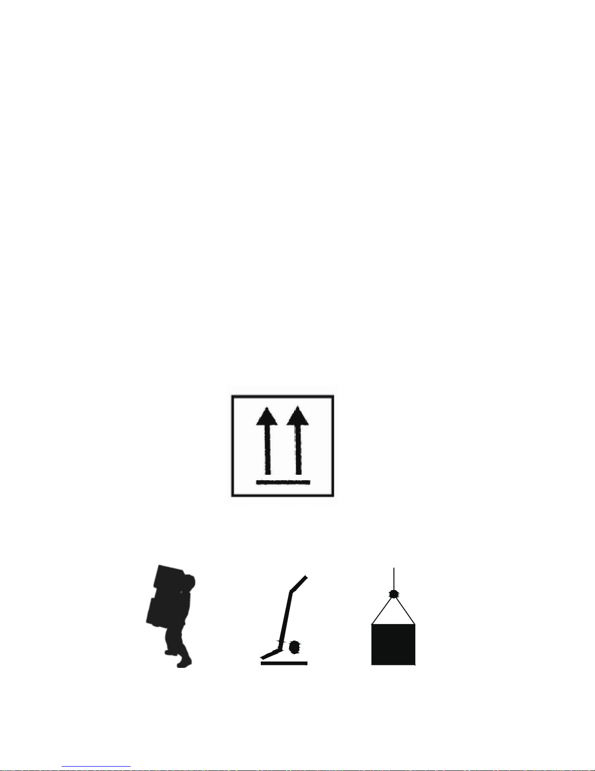
Hydraulic torque wrench transport information.
1 Handle with care.、
2 The shipment should be vertical upward, as shown in the figure 9-1.、
FIG 9-1
3 Product handling, generally using portable, car handling and lifting and moving,、
as shown in the figure 9-2.
FIG 9-2
13
14

15

16

17

S series drawing
NOTE:30# can not part from the piston rod assembly
19
17
16
15
2728
29
30
31
32
33
34
35
34
36
37
38
39
40
41
26
25
24
1
2
15
16
17
18
9
8
7
6
3
4
5
2
20
21
22
23
14
13
12
11
10
S17、S45、S100、S150、S370
series
30# Part drawing
30-4
30-3
30-2
30-1
12

S17 S45 S100 S150 S370
ITEM NAME NUMBER NUMBER NUMBER NUMBER NUMBER
1
BODY
1 1 1 1 1
2
SCREW
2 2 2 2
3
REACTION ARM
1 1 1 1 1
4
REACTION ARM COVER
1 1 1 1 1
5
(REACTION ARM)SCREW
2 2 2 2 2
6
(REACTION ARM)SPRING
1 1 1 1 1
7
PIN
1 1 1 1 1
8
SCREW
1 1 1 1 1
9
SCREW
1 1 1 1 1
10
SIDE RATCHET DRIVER
1 1 1 1 1
11
(BODY)REATINING RING
1 1 1 1
12
(BODY)SCREW
1 1 1 1 1
13
STEEL BALL
1 1 1 1
14
(BODY)SCREW
1 1 1 1
15
BUSHING
2 2 2 2
16
SIDE RATCHET DRIVER
2 2 2 2 2
17
REATINING RING
2 2 2 2 2
18
DRIVE RETAINER
1 1 1 1 1
19
SQUARE DRIVE
1 1 1 1 1
20
SWIVEL JOINT
1 1 1 1 1
21
COUPLER
2 2 2 2 2
22
QUICK COUPLER(MALE)
1 1 1 1 1
23
QUICK COUPLER(FEMALE)
1 1 1 1 1
24
SCREW
2 2 2 2 2
25
PISTON HOUSING
1 1 1 1 1
26
BACK UP RING
O RING
1 1 1 1 1
27
O RING
1 1 1 1 1
28 1 1 1 1 1
29
BACK UP RING
1 1 1 1 1
30
PISTON ASSEMBLY
1 1 1 1 1
31
O RING
1 1 1 1 1
32
RETAINING SCREW
1 1 1 1 1
33
U RING
1 1 1 1 1
34
SCREW
2 2 3 3 4
35
BODY COVER
1 1 1 1 1
36
PIN SCREW
2 2 2 2
37
PIN
1 1 1 1 1
38
RATCHET PLATE
1 1 1 1 1
39
DRIVE PAWL SPRING
2 2 2 2 2
40
DRIVE PAWL
1 1 1 1 1
41
RATCHET
1 1 1 1 1
30-1
PISTON COVER
1 1 1 1 1
30-2
RETAINING RING
1 1 1 1 1
30-3
RETAINING RING
1 1 1 1 1
30-4
PISTON HOOK
1 1 1 1 1
S series partlist
13

H series drawing
H27、H54、H120
series
7
12
11
16
15
13
14
5
4
1
2
8
9
17
6
4
1
2
3
10.1
H210、H430
series
7
12 11
16
17
6
4
1
2
10.2
14

H27 H45 H120 H210 H430
ITEM NAME NUMBER NUMBER NUMBER NUMBER NUMBER
1
SCREW
4 4 4 4 4
2
SCREW
4 4 4 4 4
3
RIGHT OUTER PLATE
1 1 1 1 1
4
COPPER BELT
2 2 2 2 2
5
DRIVE PLATE
1 1 1 1 1
6
RATCHET
1 1 1 1 1
7
LEFT OUTER PLATE
1 1 1 1 1
8
REACTION ARM
1 1 1 1 1
9
PIN
2 2 2 2 2
10.1 1 1 1
10.2 1 1
11
SHROULD
1 1 1 1 1
12
SHROULD SCREW
2 2 2 2 2
13
PIN
1 1 1 1 1
14
SPRING
1 1 1 1 1
15
DRIVE PIN
1 1 1 1 1
16
SPRING
1 1 1 1 2
17
RATCHET PAWL
1 1 1 1 1
REACTION PAWL
H series work-head partlist
15

H series power-head drawing
H27、H54、H120、H210、H430 series
H27、H54、H120
H210
2.2
4
4
5
24
26
1
6
7
8
9
7
8
10
10
13
14
15
18
17
16
15
21
23
20
22
19
17
18
12
3
25
2.1
4
5
4
2.2
4
14
1
11
6
7
3
8
9
8
9
10
4
5
13
12
H430
16

H27 H54 H120 H210 H430
ITEM NAME NUMBER NUMBER NUMBER NUMBER ITEM NUMBER
1
BODY
1 1 1 1 1
BODY
1
2.1 1 1 1
2.2 1 2.2 1
3
PISTON COVER
1 3
PISTON COVER
1
4
SLIDE BLOCK
2 2 2 2 4
SLIDE BLOCK
2
5
PIN
1 1 1 1 5
PIN
1
6
(BODY)U RING
1 1 1 1 6
BUSHING
1
7
O RING
2 2 2 2 7
(BODY)U RING
1
8
RETAINING RING
2 2 2 2 8
(PISTON)O RING
2
9
(PISTON)U RING
1 1 1 1 9
REATINING RING
2
10
O RING
2 1 1 1 10
PISTON HOUSING
1
11
BODY SCREW
4 1 1 1 11
SCREW
2
12
PISTON HOUSING
1 1 1 1 12
PIN
1
13
SCREW
2 2 2 13
SCREW
1
14
SCREW
8 8 8 8 14
HOSE SWIVEL JOINT
1
15
SCREW
6 3 3 3
16
SWIVEL JOINT
1 1 1 1
17
O RING
6 6 6 6
18
REATINING SPRING
2 2 2 2
19
HOSE SWIVEL JOINT
1 1 1 1
20
STEEL BALL
1 1 1 1
21
SPRING SEAT
1 1 1 1
22
SPRING
1 1 1 1
23
(SWIVEL JOINT)SCREW
1 1 1 1
24
(BODY)SCREW
1 1 1
25
SCREW
1 1 1 1
26
PIN
1 1 1 1
PISTON HOOK PISTON HOOK
H series power-head partlist
17

TROUBLE SHOOTING GUIDE
TROUBLE PROBABLE CAUSE SOLUTION
Piston will not advance
or retract
Couplers are not securely attached
to the tool or pump
Check the coupler connections and make
certain that they are connected
Coupler is defective
Replace any defective Coupler
Defect ive remote control unit
Dirt in the direction-contol valve o
the pump unit
Disassemble the pump and clean the
direction-control valve
Replace the button and/orcon trol pendent
Piston will not retract
Hose connections reversed
Make certain the advance on the pump is
connected to the advance on the tool and
retract on the pump is connected to the
retract on the tool
Retract pin and/or spring broken
Retract hose n ot connected
Replace the broken pin and/or spring
Connect the retract hose securely
Cylinder will not build up
pressure
Piston Seal and /or End Plug Seal leaking Replace any defective o-ring
Replace any defective Coupler
Coupler is defective
Square Drive will n ot turn
Grease or dirt build up in the teeth of
the Ratchet an d Segment Pawl
Disassemble the Ratchet and clean the
grease or dirt out of te teeth
Worn or broken teeth on Ratchet an
/or Segment Pawl
Replace any worn or damaged parts
Pump will not build up
pressure
Defect ive relief valve
Inspect,adjust or replace the relief va lve
Electric power source is too lo w
Make certain the amperage,voltage and
any extension aord size comply with the
pump manual requirements
Defect ive Gauge
Replace the Gauge
Low oi l level
Check and fill the pum p reservoir
Clogged filter
Inspec t,clean and/or replace the pump filter
Nut Returns with retract
stroke
Ball Plungers are not engaging the
Drive Sleeves
Thread the Ball Pungers to the correct
depth in the Housing
18

WWW.WRENCHINA.COM

S系列及H系列液压扭矩扳手操作保养手册
一 收货须知(开箱检查)
①
②
③
④
⑤
⑥
⑦
序号
本体
360°旋转接头
快速接头
销固装置
360°旋转反力臂
四方驱动轴
驱动轴锁紧器
名称
安全第一!!
液压扭矩扳手是一种动力工具,使用前应仔细阅读所有的说明、警告和注意事项, 遵守安全操作
以避免在操作设备发生人身或设备的损伤! 对因为不安全操作及错误操作导致的损坏本公司不于
负责任。
仔细检查产品外观有无损伤,是否有运输损坏。运输损坏不包括在保修范围内。 如果发现因货运
受损,应及时向货运商申报。货运商应支付运输损坏带来的所有维修和更换费用。
WREN公司的S系列和H 双系列液压扭矩扳手采用铝钛合金及超高强度合金材料制造,为手动控制,
作用的液 误差 压设计,可以锁紧及松开螺栓连接,广泛适合用于大力矩螺栓拆卸,扭矩精确可调,
产品描述
S系列驱动型液压扭矩扳手:
本操作手册内容包含S和H系列的液压扭矩扳手操作规程、警告以及注意事项和事故排除。使用前请
仔细阅读本手册,理解其内容并妥善保管。本说明书仅作为最终用户参考。
①
② ③
④
⑤
⑥⑦
1
+
-
不超过 3%。

2
使用WREN原厂高性能的套筒。
警告事项
警告
警告
警告
注意
警告
注意
注意
注意
为避免人身伤害及可能的设备损伤,要确保每一个液压元件最高承受700bar的工作压力。
不要超过设备的额定负荷尽量减少超载的危险;在系统中使用压力表以显示操作负载。压力表是显
示系统内发生情况的窗口。使用液压扳手时不得超过其允许的最大扭矩。
尽快用WREN原厂零件替换损坏的零件。
避免损坏液压油管,使用中应该避免液压油管严重弯曲和缠绕。使用弯曲或缠绕的油管将产生过大
严重弯曲和缠绕使油管内部损坏,从而过早报废。
不要将重物掉到或压到油管上。严重冲击可引起油管内部金属线损坏,加压时被损坏的油管可能破
裂。不能用液压油管拖拉及吊拿其它液压部件(如:泵、液压扳手、阀等)。
为避免损坏设备及人身伤害,不得拆掉扳手上的护板,不得改动扳手及附件,不得改变旋转接头上
不正确的连接会导致故障及危险。连接前应保持快速接头清洁,使用后旋上防尘帽。
不得使用破旧的套筒和插头。不得用公制套筒扭英制的螺母和螺栓,反之亦然。
H系列中空型液压扭矩扳手
序号
名称
①
②
③
④
⑤
⑥
⑧
⑦
工作头
勾头
动力头
快速接头
反作用挡板
快速组合销
棘轮
360 360 旋转接头°× °
①
② ③ ④
⑤
⑥
⑧
⑦
用插销将套筒驱动头紧固以避免套筒脱落。
的背压。
的安全阀。
二、警 告事项 和警告 标志

警告标志
警告标志如下表所示
IF DRIVE STICKS OUT RIGHT,
IT'S SET FOR TIGHTEN.
LEFT. IT'S SET FOR LOOSE!
LOCK REACTION
ARM BEFORE
USING TOOL!
警告标志
意义
粘贴位置
禁止用手触摸
反力臂
驱动轴右紧左松
工作头
使用前固定好反力臂
反力臂

3
螺栓
表1
三、螺栓预紧力推荐表
强度等级
4.8 6.8 8.8 10.9
最小破断强度
392MPa 588MPa 784MPa 941MPa
材质
一般构造用钢 机械构造用钢 铬钼合金钢 镍铬钼合金钢
螺母
KGM N.m
22 7 69 10 98 14 137 17 165
24 10 98 14 137 21 206 25 247
27 14 137 21 206 29 284 35 341
30 18 176 28 296 41 402 58 569
32 23 225 34 333 55 539 78 765
36 32 314 48 470 70 686 100 981
41 45 441 65 637 105 1029 150 1472
46 60 588 90 882 125 1225 200 1962
50 75 735 115 1127 150 1470 210 2060
55 100 980 150 1470 180 1764 250 2453
60 120 1176 180 1764 220 2156 300 2943
65 155 1519 240 2352 280 2744 390 3826
70 180 1764 280 2744 320 3136 450 4415
75 230 2254 350 3430 400 3920 570 5592
80 280 2744 420 4116 480 4704 670 6573
85 360 3528 530 5149 610 5978 860 8437
90 410 4018 610 5978 790 7742 1100 10791
95 510 4998 760 7448 900 8820
100 580 5684 870 8526 1100 10780
105 660 6468 1000 9800 1290 12642
110 750 7350 1100 10780 1500 14701
115 830 8143 1250 12250 1850 18130
120 900 8820 1400 13720 2250 22050
130 1080 10584 1650 16170 2500 24500
145 1400 13720 2050 20090
155 1670 16366 2550 24990
175 2030 19894 3050 29890
mm KGM N.m KGM N.m KGM N.m
建议锁紧扭矩值为:表中数值 80%×
例如:M52,8.8级螺栓,则锁紧力矩为4704?0%=3763N.m
拆松力矩为锁紧力矩的1.5~2倍
例如:上例锁紧力矩为3763N.m,则其拆松力矩为3763×1.5(2)=5645(7526)N.m
12.9
1176MPa
镍铬钼合金钢
23 225
36 363
49 480
69 680
93 911
120 1176
180 1764
240 2352
250 2450
300 2940
370 3626
470 4606
550 5390
680 6664
850 8330
1050 10290
1350 13230
KGM N.m
14
16
18
20
22
24
27
30
33
36
39
42
45
48
52
56
60
64
68
72
76
80
85
90
100
110
120
M
扭矩值 扭矩值 扭矩值 扭矩值
表中数值为德国工业标准,在螺栓达到屈服极限的80%时所测定的。
扭矩值
注:
反力臂必须 放 置 在 一 个绝对停止
的位置,请 勿 把 手 臂 用作固定手
柄,做好预 防 措 施 确 保操作者的
手不被夹在 手 臂 和 坚 固物体中间。
保持身体姿 态 平 衡 和 稳固。
请勿靠拿管 子 来 移 动
工具。
最大操作压 力 为1 0 0 00
psi(700 b a r)
在安装、移 动 或 在 工 具上
调节附件, 或 者 给 工 具做
保养前,请 先 关 闭 泵 和断
开电源。
请勿使用损 坏 的 , 磨 损的或老
化的液压油 管 和 装 置 。

4
准备
扳手及液压泵之间是由工作压力均为700bar的钢丝编织的复式油管连接的。每根油管的两端均有凹
接头以及凸接头,以保证泵与扳手之间的正确连接。不得随意变动旋转接头上的任何螺栓。这是厂
家为了安全而设定的。只有受过专业培训者才能去调节。
连接油管
图3
方型驱动轴换向
按住锁紧器中间的圆型按扭(图4),并轻拉驱动轴,以解开驱动轴与锁紧器的啮合,驱动轴就可以
将驱动轴放入扳手内,确定方向,使其与花键套完全啮合,然后转动驱动轴使之于花键套以及棘轮
槽啮合,通过棘轮推动驱动轴转动。
确定是拆松,还是锁紧螺母
通过按下驱动方轴锁紧器;取出方头驱动轴;按图进行左右换向,装上驱动轴锁紧器,按下反作用
力臂上的力臂夹,按合适方位装入反作用力臂。拆锁时方轴方向见图(5)所示。
驱动轴
锁紧器
按钮
图4
图5
拆松
紧固
注意
S系列
拉出。

5
连接泵站
将泵的高压出口(H或A)与液压扳手的高压出口(H或A)、泵的低压出口(L或R)与液压扳手的低
压出口(L或R)分别用高压油管连接起来。连接时油管上的快速接头应插到底,然后用手拧紧固定
螺母。
将扳手置于空地上。打开泵的电源开关,启动泵,检查泵是否运转正常。按线控开关上的按扭,此
时方轴开始转动,直到扳手到位停止转动,压力表由"0"急速上升至调定压力,松开按钮,扳手自动
回程;待扳手自动回程到位后,压力表由"0"急速上升至7.5Mpa。这时再重新按下按钮,一个新的
循环开始。反复几次,使扳手空转数次,观察扳手转向,确定方向后再将扳手放至套筒上。
调整压力
扳手与泵连接号放置在空地上,一手将线控开关按钮按下驱动轴开始转动,直到扳手到位停止转动,
压力表由“0”急速上升,另一只手调整油泵调压阀,调整压力表中指针至所需压力。
图6
T型旋钮
锁紧环
1:力矩的设定
首先可根据设计要求设定力矩;如无设计力矩,建议按表(1)螺栓预紧力推荐表中数据。具体方法为:
设定力矩=(表中数矩) (80%-90%)×
例如:M48是螺栓、8.8级,表中建议预紧力为3920N.m,则设定力矩为: 3920 80%=3136N.m。×
2:泵站压力设定
根据所需的力矩值及所用扳手型号来设定泵站压力。如上述M48螺栓、8.8级设定力矩为3136N.m, 选
用S45 S45一列,查出对应于3158N.m力矩时泵站的压力为49Mpa,所以驱动型液压扭矩扳手,则查表中
泵站压力应设定至49Mpa。
3:确定扳手转向确为锁紧方向,将扳手放在螺母上反复执行试运转中第三条的动作,直至螺母不
使用举例
注意:扳手不用时,应即时关闭油泵电源!
将泵站压力调整到最高, 确认扳手转向, 确认为拆松方向,将扳手放到螺母上,找好反作用支点,
靠稳,反复执行试运转中第三条动作,直至将螺母拆下。
拆松
试运转
动为止。

6
H系列
工作头和动力头的连接与拆分
工作头与动力头的组合与拆分:将动力头上的长销轴卡入工作头的沟槽,然后按下动力头,对齐组
合销口,再插入快速组合销定位(图7)。
拉出快速组合销,向上拉起动力头,然后沿着沟槽方向,将动力头和工作头分开。
工作头
动力头
快速组合销
图7
中空扳手的使用位置
中空扳手操作细则
中空扳手的松紧程序也是左松右紧,工作时一定要确保反作用力臂或直角靠在一个牢靠的反作用支
点上。见(图8)
图8
紧固 拆松
中空扳手方向示意图
确定要拆松(锁紧)螺母的大小,选择适合的动力头、工作头及变径套附件。连接泵站将泵的高压
出 H或A)与液压扳手的高压出口(H或A)、泵的低压出口(L或R)与液压扳手的低压出口(L或R)口(
分别用高压油管连接起来。连接时油管上的快速接头应插到底,然后用手拧紧固定螺母。
仔细检查油管接头是否连接可靠,泵中是否有油。最后将泵的电源插头插入电源。
准备
警告 严禁无油运转!!

7
将扳手置于空地上。打开泵的电源开关,启动泵,检查泵是否运转正常。按线控开关上的任意一只
按扭,此时棘轮开始转动,当扳手运转到位停止转动,压力表由"0"急速上升至调定压力,松开按
钮,扳 急速上升至7.5Mpa。重新按下按钮,此时手自动回程;待扳手自动回程到位,压力表由"0"
扳手转动,一个新的循环开始。反复几次,使扳手空转数次,观察扳手转向,以确定是拆松还是锁
紧螺母,无异常时,才能将扳手放至螺母上。
试运转
注意:扳手不用时,应即时关闭油泵电源!
调整压力
一手将线控开关按钮按下,当扳手到位停止转动,压力表由"0"急速上升,另一只手调整油泵压阀,
调整压力表中指针至所需压力。
将泵站压力调整到最高,确认扳手转向,确认为拆松方向,将扳手放到螺母上,找好反作用支点,
锁紧
首先可根据设计要求设定力矩;如无设计力矩,建议按螺栓预紧力推荐表中数据来设定力矩。具体
方 =(表中数矩) 80%-90%),例如:8.8级、M48是螺栓,表中建议预紧力为3920N.m,法为:设定力矩 ×(
则设定力矩为: 3920 80%=3136N.m。×
2、泵站压力设定
根据所需的力矩值及所用扳手型号来设定泵站压力。如上述8.8级、M48螺栓设定力矩为3136N.m,
选用H54型扳手,则查表中H54一列,查出对应于3144N.m力矩时泵站的压力为41Mpa,所以泵站压力
应设定至41Mpa。
3 、确定扳手转向确为锁紧方向,将扳手放在螺母上反复执行第二项中第三条的动作,直至螺母不
拆松
动为止。
靠稳,反复执行第二项中第三条动作,直至将螺母拆下。
1、力矩设定

8
7
8
9
10
11
12
13
14
15
16
17
18
19
20
21
22
23
24
25
26
27
28
29
30
31
32
33
34
35
36
37
38
39
40
41
42
43
44
45
46
47
48
49
50
51
52
53
54
55
56
57
58
59
60
61
62
63
64
65
66
67
68
69
70
1727
N.m N.m N.m N.m
S17
S45 S100 S150
S370
197
221
246
270
295
319
344
369
393
418
442
467
491
516
541
565
590
614
639
663
688
713
737
762
786
811
835
860
885
909
934
958
983
1007
1032
1057
1081
1106
1130
1155
1179
1204
1229
1253
1278
1302
1327
1351
1376
1401
1425
1450
1474
1499
1523
1548
1573
1597
1622
1646
1671
1695
452
517
581
646
710
775
839
904
969
1033
1098
1162
1227
1291
1356
1421
1485
1550
1614
1679
1743
1808
1873
1937
2002
2066
2131
2260
2195
2325
2389
2454
2518
2583
2647
2712
2777
2841
2906
2970
3035
3099
3164
3229
3293
3358
3422
3487
3551
3616
3681
3810
3745
3874
3939
4003
4068
4133
4197
4262
4326
4391
4455
4529
1006
1150
1293
1437
1581
1725
1868
2012
2156
2299
2443
2587
2731
2874
3018
3162
3305
3449
3593
3737
3880
4024
4168
4311
4455
4599
4743
4886
5030
5174
5317
5461
5605
5749
5892
6036
6180
6323
6467
6611
6755
6898
7042
7186
7329
7473
7617
7761
7904
8048
8192
8335
8479
8623
8767
8910
9054
9198
9341
9485
9629
9773
9916
10064
1497
1711
1925
2139
2352
2566
2780
2994
3208
3422
3636
3849
4063
4277
4491
4705
4919
5133
5346
5560
5774
5988
6202
6416
6630
6843
7057
7271
7485
7699
7913
8127
8340
8554
8768
8982
9196
9410
9624
9837
10051
10265
10479
10693
10907
11121
11334
11548
11762
11976
12190
12404
12618
12831
13045
13259
13473
13687
13901
14115
14328
14542
14756
14974
3699
4227
4756
5284
5813
6341
6870
7398
7926
8455
8983
9512
10040
10569
11097
11625
12154
12682
13211
13739
14268
14796
15324
15853
16381
16910
17438
17967
18495
19023
19552
20080
20609
21137
21666
22194
22722
23251
23779
24308
24836
25365
25893
26421
26950
27478
28007
28535
29064
29592
30120
30649
31177
31706
32234
32763
33291
33819
34348
34876
35405
35933
36462
36992
N.m
172
Mpa
型号
六、S液压 扭矩扳 手压力- -扭矩对照 表
表2

9
型号 S17 S45 S100 S150 S370
ft.lbsft.lbsft.lbsft.lbs ft.lbspsi
1200
1400
1600
1800
2000
2200
2400
2600
2800
3000
3200
3400
3600
3800
4000
4200
4400
4600
4800
5000
5200
5400
5600
5800
6000
6200
6400
6600
6800
7000
7200
7400
7600
7800
8000
8200
8400
8600
8800
9000
9200
9400
9600
9800
150
175
200
226
251
276
301
326
351
376
401
426
451
476
501
526
551
576
601
626
651
677
702
727
752
777
802
827
852
877
902
927
952
977
1002
1027
1052
1077
1102
1128
1153
1178
1203
1228
1253
329
395
461
527
593
658
724
790
856
922
988
1054
1119
1185
1251
1317
1383
1449
1514
1580
1646
1712
1778
1844
1909
1975
2041
2107
2173
2239
2305
2370
2436
2502
2568
2634
2700
2765
2831
2897
2963
3029
3095
3161
3226
3292
733
879
1026
1172
1319
1465
1612
1759
1905
2052
2198
2345
2491
2638
2784
2931
3078
3224
3371
3517
3664
3810
3957
4103
4250
4396
4543
4690
4836
4983
5129
5276
5422
5569
5715
5862
6008
6155
6302
6448
6595
6741
6888
7034
7181
7327
1090
1308
1745
1963
2181
2399
2617
2835
3053
3271
3489
3707
3925
4143
4361
4580
4798
5016
5234
5452
5670
5888
6106
6324
6542
6760
6978
7196
7415
7633
7851
8069
8287
8505
8723
8941
9159
9377
9595
9813
10031
10249
10468
10686
10904
2694
3233
3772
4311
4850
5388
5927
6466
7005
7544
8083
8621
9160
9699
10238
10777
11316
11854
12393
12932
13471
14010
14549
15088
15626
16165
16704
17243
17782
18321
18859
19398
19937
20476
21015
21554
22092
22631
23170
23709
24248
24787
25325
25864
26403
26942
10000
1000 125
S液压扭 矩扳手 压力--扭 矩对照表
表3
1527

七、H系列液压扭矩扳手压力--扭矩对照表
7
8
9
10
11
12
13
14
15
16
17
18
19
20
21
22
23
24
25
26
27
28
29
30
31
32
33
34
35
36
37
38
39
40
41
42
43
44
45
46
47
48
49
50
51
52
53
54
55
56
57
58
59
60
61
62
63
64
65
66
67
68
69
N.m N.m N.mN.m N.m N.m N.m N.m N.m
H27
H54 H120 H210 H430
螺母范围
19~46 50~60 27~65 70~80 50~80 85~105 70~100 105~115 80~117 120~175
262
299
337
374
412
449
487
524
561
599
636
674
711
749
786
823
861
898
936
973
1011
1048
1085
1123
1160
1198
1235
1273
1310
1347
1385
1422
1460
1497
1535
1572
1609
1647
1684
1722
1759
1797
1834
1871
1909
1946
1984
2021
2059
2096
2133
2171
2208
2246
2283
2321
2358
2395
2433
2470
2508
2545
2583
2625
306
350
393
437
481
525
568
612
656
699
743
787
831
874
918
962
1005
1049
1093
1137
1180
1224
1268
1311
1355
1399
1443
1486
1530
1574
1617
1661
1705
1749
1792
1836
1880
19
23
1967
2011
2055
2098
2142
2186
2229
2273
2317
2361
2404
2448
2492
2535
2579
2623
2667
2710
2754
2798
2841
2885
2929
2973
3016
3068
537
614
690
767
844
921
997
1074
1151
1227
1304
1381
1458
1534
1611
1688
1764
1841
1918
1995
2071
2148
2225
2301
2378
2455
2532
2608
2685
2762
2838
2915
2992
3069
3145
3222
3299
3375
3452
3529
3606
3682
3759
3836
3912
3989
4066
4143
4219
4296
4373
4449
4526
4603
4680
4756
4833
4910
4986
5063
5140
5217
5293
5372
603
689
775
861
948
1034
1120
1206
1292
1378
1464
1551
16
37
1723
1809
1895
1981
2067
2154
2240
2326
2412
2498
2584
2670
2757
2843
2929
3015
3101
3187
3273
3360
3446
3532
3618
3704
3790
3876
3963
4049
4135
4221
4307
4393
4479
4566
4652
4738
4824
4910
4996
5082
5169
5255
5341
5427
5513
5599
5685
5772
5858
5944
6037
1173
1341
1508
1676
1843
2011
2178
2346
2514
2681
2849
3016
3184
3351
3519
3687
3854
4022
4189
4357
4524
4692
4860
5027
5195
5362
5530
5697
5865
6033
6200
6368
6535
6703
6870
7038
7206
7373
7541
7708
7876
8043
8211
8379
8546
8714
8881
9049
92
16
9384
9552
9719
9887
10054
10222
10389
10557
10725
10892
11060
11227
11395
11562
11737
1434
1639
1844
2049
2253
2458
2663
2868
3073
3278
3483
3687
3892
4097
4302
4507
4712
4917
5121
5326
5531
5736
5941
6146
6351
6555
6760
6965
7170
7375
7580
7785
7989
8194
8399
8604
8809
9014
9219
9423
9628
9833
10038
10243
10448
10653
10857
11062
11267
11472
11677
11882
12087
12291
12496
12701
12906
13111
13316
13521
13725
13930
14135
14349
2121
2424
2727
3030
3333
3636
3939
4242
4545
4848
5151
5454
5
757
6060
6363
6666
6969
7272
7575
7878
8181
8484
8787
9090
9393
9696
9999
10302
10605
10908
11211
11514
11817
12120
12423
12726
13029
13332
13635
13938
14241
14544
14847
15150
15453
15756
16059
16362
16665
16968
17271
17574
17877
18180
18483
18786
19089
19392
19695
19998
20301
20604
20907
21216
2312
2642
2973
3303
3633
3963
4294
4624
4954
5285
5615
5945
6275
6606
6936
7266
7597
7927
8257
8587
8918
9248
9578
9909
10239
10569
10899
11230
11560
11890
12221
12551
12881
13211
13542
13872
14202
14533
14863
15193
15523
15854
16184
16514
16845
17175
17505
17835
18166
18496
18826
19157
19487
19817
20147
20478
20808
21138
21469
21799
22129
22459
22790
23124
4379
5005
5630
6256
6881
7507
8132
8758
9384
10009
10635
11260
11886
12511
13137
13763
14388
15014
15639
16265
16890
17516
18142
18767
19393
20018
20644
21269
21895
22521
23146
23772
24397
25023
25648
26274
26900
27525
28151
28776
29402
30027
30653
31279
31904
32530
33155
33781
34406
35032
35658
36283
36909
37534
38160
38785
39411
40037
40662
41288
41913
42539
43164
43792
4848
5541
6233
6926
7618
8311
9003
9696
10389
11081
11774
12466
13159
13851
14544
15237
15929
16622
17314
18007
18699
19392
20085
20777
21470
22162
22855
23547
24240
24933
25625
26318
27010
27703
28395
29088
29781
30473
31166
31858
32551
33243
33936
34629
35321
36014
36706
37399
38091
38784
39477
40169
40862
41554
42247
42939
43632
44325
45017
45710
46402
47095
47787
48481
10
Mpa
70
型号
N.m
表4

H系列液压扭矩扳手压力--扭矩对照表
ft.lbs ft.lbs ft.lbs ft.lbs ft.lbs ft.lbs ft.lbs ft.lbs ft.lbs ft.lbs
H54 H120 H210 H430
191
229
267
305
343
382
420
458
496
534
572
611
649
687
725
763
801
840
878
916
954
992
1030
1069
1107
1145
1183
1221
1259
1298
1336
1374
1412
1450
1488
1527
1565
1603
1641
1679
1717
1756
1794
1832
1870
1908
1000
1200
1400
1600
1800
2000
2200
2400
2600
2800
3000
3200
3400
3600
3800
4000
4200
4400
4600
4800
5000
5200
5400
5600
5800
6000
6200
6400
6600
6800
7000
7200
7400
7600
7800
8000
8200
8400
8600
8800
9000
9200
9400
9600
9800
10000
223
267
312
357
401
446
490
535
579
624
669
713
758
802
847
892
936
981
1025
1070
1114
1159
1204
1248
1293
1337
1382
1426
1471
1516
1560
1605
1649
1694
1738
1783
1828
1872
1917
1961
2006
2051
2095
2140
2184
2229
391
469
548
626
704
782
860
939
1017
1095
1173
1252
1330
1408
1
486
1565
1643
1721
1799
1877
1956
2034
2112
2190
2269
2347
2425
2503
2581
2660
2738
2816
2894
2973
3051
3129
3207
3286
3364
3442
3520
3598
3677
3755
3833
3911
439
527
615
703
791
878
966
1054
1142
1230
1318
1405
1493
1581
1669
1757
1845
1933
2020
2108
2196
2284
2372
2460
2547
2635
2723
2811
2899
2987
3074
3162
3250
3338
3426
3514
3601
3689
3777
3865
3953
4041
4129
4216
4304
4392
854
1025
1196
1367
1538
1709
1880
2051
2221
2392
2563
2734
2905
3076
3247
3418
3588
3759
3930
4101
4272
4443
4614
4785
4
955
5126
5297
5468
5639
5810
5981
6152
6322
6493
6664
6835
7006
7177
7348
7519
7689
7860
8031
8202
8373
8544
1044
1253
1462
1671
1880
2089
2298
2507
2716
2925
3133
3342
3551
3760
3969
4178
4387
4596
4805
5014
5222
5431
5640
5849
6058
6267
6476
6685
6894
7102
7311
7520
7729
7938
8147
8356
8565
8774
8983
9191
9400
9609
9818
10027
10236
10445
1545
1854
2163
2472
2781
3090
3399
3708
4017
4326
4635
4944
5253
5562
5871
6180
6488
6797
7106
7415
7724
8033
8342
8651
8960
9269
9578
9887
10196
10505
1081
4
11123
11432
11741
12050
12359
12668
12977
13286
13595
13904
14213
14522
14831
15140
15449
1684
2021
2358
2694
3031
3368
3705
4042
4378
4715
5052
5389
5726
6062
6399
6736
7073
7410
7746
8083
8420
8757
9094
9430
9767
10104
10441
10778
11114
11451
11788
12125
12462
12798
13135
13472
13809
14146
14482
14819
15156
15493
15830
16166
16503
16840
3190
3827
4465
5103
5741
6379
7017
7655
8293
8931
9569
10206
10844
11482
12120
12758
13396
14034
14672
15310
15948
16586
17223
17861
18499
19137
19775
20413
21051
21689
22327
22965
23603
24240
24878
25516
26154
26792
27430
28068
28706
29344
29982
30619
31257
31895
3531
4237
4944
5650
6356
7062
7769
8475
9181
9887
10593
11300
12006
12712
13418
14125
14831
15537
16243
16949
17656
18362
19068
19774
20481
21187
21893
22599
23306
24012
24718
25424
26130
26837
27543
28249
28955
29662
30368
31074
31780
32486
33193
33899
34605
35311
psi
型号
H27
螺母范围
19~46 50~60 27~65 70~80 50~80
85~105
70~100 105~115 80~117 120~175
11
表5

八、S系列液压扭矩扳手装配图
说明:30#部件为活塞的不可拆分部件
19
17
16
15
2728
29
30
31
32
33
34
35
34
36
37
38
39
40
41
26
25
24
1
2
15
16
17
18
9
8
7
6
3
4
5
2
20
21
22
23
14
13
12
11
10
S17、S45、S100、S150、S370系列
30#部件拆分图
30-4
30-3
30-2
30-1
12

S17 S45 S100 S150 S370
序列 名称 数量 数量 数量 数量 数量
1
本体
1 1 1 1 1
2
螺钉
2 2 2 2
3
反力臂
1 1 1 1 1
4
马掌
1 1 1 1 1
5
(马掌)螺钉
2 2 2 2 2
6
(反力臂)压簧
1 1 1 1 1
7
固定销
1 1 1 1 1
8
固定螺钉
1 1 1 1 1
9
螺钉
1 1 1 1 1
10
花键轴
1 1 1 1 1
11
(本体)卡簧
1 1 1 1
12
(本体前)堵头
1 1 1 1 1
13
钢球
1 1 1 1
14
(本体上)堵头
1 1 1 1
15
钢套
2 2 2 2
16
自由花键套
2 2 2 2 2
17
(钢套)卡簧
2 2 2 2 2
18
锁紧器
1 1 1 1 1
19
驱动轴
1 1 1 1 1
20
旋转接头
1 1 1 1 1
21
外接头
2 2 2 2 2
22
凸接头
1 1 1 1 1
23
凹接头
1 1 1 1 1
24
碰珠螺钉
2 2 2 2 2
25
缸盖
1 1 1 1 1
26
(缸盖)挡圈
1 1 1 1 1
27
(缸盖)O型圈
1 1 1 1 1
28
(活塞)
O 形圈
1 1 1 1 1
29
(活塞)挡圈
1 1 1 1 1
30
活塞部件
1 1 1 1 1
31
(本体)O型圈
1 1 1 1 1
32
压紧螺母
1 1 1 1 1
33
(压紧螺母)U型圈
1 1 1 1 1
34
(盖板)螺钉
2 2 3 3 4
35
盖板
1 1 1 1 1
36
(销轴)螺钉
2 2 2 2
37
销轴
1 1 1 1 1
38
驱动板
1 1 1 1 1
39
(棘爪)压簧
2 2 2 2 2
40
棘爪
1 1 1 1 1
41
棘轮
1 1 1 1 1
30-1
活塞杆
1 1 1 1 1
30-2
(连杆轴)卡簧
1 1 1 1 1
30-3
(连杆轴)钢丝挡圈
1 1 1 1 1
30-4
连杆轴
1 1 1 1 1
九、S系列液压扭矩扳手零件详表
型号

十、H系列液压扭矩扳手工作头装配图
H27、H54、H120系列
7
12
11
16
15
13
14
5
4
1
2
8
9
17
6
4
1
2
3
10.1
H210a H430系列
7
12 11
16
17
6
4
1
2
10.2

H27 H45 H120 H210 H430
序号
名称 数量 数量 数量 数量 数量
1
(连接垫板)螺钉
4 4 4 4 4
2
(反力支板)螺钉
4 4 4 4 4
3
右墙板
1 1 1 1 1
4
铜带
2 2 2 2 2
5
驱动板
1 1 1 1 1
6
棘轮
1 1 1 1 1
7
左墙板
1 1 1 1 1
8
反力支板
1 1 1 1 1
9
定位销
2 2 2 2 2
10.1 1 1 1
10.2 1 1
11
盖板
1 1 1 1 1
12
(盖板)螺钉
2 2 2 2 2
13
弹性销
1 1 1 1 1
14
扭簧
1 1 1 1 1
15
驱动销
1 1 1 1 1
16
压簧
1 1 1 1 2
17
棘爪
1 1 1 1 1
连接垫板
十一、H系列液压扭矩扳手工作头零件表
型号
连接垫板

H27、H54、H120
H210
2.2
4
4
5
24
26
1
6
7
8
9
7
8
10
10
13
14
15
18
17
16
15
21
23
20
22
19
17
18
12
3
25
2.1
4
5
4
2.2
4
14
1
11
6
7
3
8
9
8
9
10
4
5
13
12
H430
十二、H系列液压扭矩扳手动力头装配图
H27、H54、H120、H210、H430系列

H27 H54 H120 H210 H430
序号 名称 数量 数量 数量 数量 序号 数量
1
本体
1 1 1 1 1
本体
1
2.1 1 1 1
2.2 1 2.2 1
3
活塞杆后盖
1 3
活塞杆后盖
1
4
滑块
2 2 2 2 4
滑块
2
5
(滑块)销
1 1 1 1 5
(滑块)销
1
6
(本体)U形圈
1 1 1 1 6
铜套
1
7
(活塞杆)(油缸盖)O形圈
2 2 2 2 7
(本体)U形圈
1
8
(活塞杆)(油缸盖)挡圈
2 2 2 2 8
(活塞杆)(油缸盖)O形圈
2
9
(活塞杆)U形圈
1 1 1 1 9
(活塞杆)(油缸盖)挡圈
2
10
(油缸盖)小O形圈
2 1 1 1 10
油缸盖
1
11
(油缸盖上)(本体侧)堵头
4 1 1 1 11
堵头
2
12
油缸盖
1 1 1 1 12
销轴
1
13
(油缸盖)顶出螺钉
2 2 2 13
碰珠螺钉
1
14
(油缸盖)螺钉
8 8 8 8 14
旋转接头
1
15
(油缸盖前)(旋转体)堵头
6 3 3 3
16
旋转体
1 1 1 1
17
(旋转体)(接头座)O形圈
6 6 6 6
18
(旋转体)(接头座)卡簧
2 2 2 2
19
接头座
1 1 1 1
20
钢球
1 1 1 1
21
弹簧座
1 1 1 1
22
弹簧
1 1
1 1
23
(接头座)堵头
1 1 1 1
24
(本体)堵头
1 1 1
25
碰珠螺钉
1 1 1 1
26
销轴
1 1 1 1
活塞杆 活塞杆
H系列液压扭矩扳手动力头零件表
型号
型号

引起的故障 可能引起的故障 解决方法
快速接头没有连接到位
检查快速接头 确保快速接头连接到底
快速接头有缺陷 替换任何有缺陷的快速接头
遥控器有缺陷 替换按钮或者遥控器
污垢进入泵上的方向控制阀 拆开泵,把方向控制器擦干净
管子接头连接错误
确保泵上的高压接头和扳手上的高压接
口相连,低压接头和低压接口相连
回油管没有连接好 安全正确连接回油管
返回销或者弹簧损坏 替换弹簧或销子
活塞密封圈放生泄漏 替换有缺陷的密封圈
接头有缺陷 替换有缺陷的接头
油渍和污垢存在与棘轮棘爪间 拆开棘轮部件,清洁棘轮、棘爪
棘轮和棘爪破旧损坏 替换任何破旧损坏的部件
有缺陷的泄压阀 检查、调节或者替换泄压阀
电压太低
确保电源、电压和其他一些数值符合泵
的操作要求
压力表有缺陷 替换压力表
油太少 检查加入足够的泵用油
过滤器堵塞 检查、清洁或者替换用过的过滤器
螺母跟着回程回转 棘轮和止退棘爪未吻合 更换棘爪或者更换棘爪压簧
泵不能建立起压力
活塞不顶升或回缩
活塞不回缩
油缸不能建立起压力
方头驱动轴不转动
故障与排除

液压扳手的日常保养及运输
1、液压扳手的保养
1.1、使用前后应检查扳手上各螺钉是否松动,发现有松动,应将拧紧,如不及时处理导致脱落
可能造成设备严重损坏。
1.2、扳手 NLGI#2二硫化钼,在混杂的环境条件下,清洗内部所有运动部件都应定期涂上优质的
和润滑都应进行。
1.3、快速接头应保持清洁,工作结束后拧上防尘帽,禁止灰尘进入液压系统导致内部阀的失效,
造成设备损坏。
1.4、连接各设备,切换方向控制阀,加压检查有无异常。
1.5、检查配管或设备是否有漏油现象,如有此类情况发生,请查明原因并对此进行处理。
1.6、扳手内部结构件都是相连的,如果有一个零件出现故障,势必会对其他零部件造成磨损,所以
要定期检查,及时保养。
2、液压扳手噪音/振动声明
3、液压扳手运输信息
液压扳手使用噪声值为: ≤70db
3.1、搬运时注意轻拿轻放。
3.2、装运时应将产品立式向上,如图9-1所示。
3.3、产品搬运一般采用手提式或小车搬运移动、吊装移动,如图9-2所示。
图9-2
图9-1

S/H系列液压扭矩扳手型号参数表
型号
扭矩(N· m)
驱动轴
(inch )
S17 172-1727 3/4
S45 452-4529 1
S100 1006-10064 1-1/2
S150 1497-14974 1-1/2
S370 3699-36992 2-1/2
型号 扭矩(N.m) 螺栓范围 (mm) 型号 扭矩(N.m) 螺栓范围 (mm)
H27 19 262-2625 19-46 H210 70 2121-21216 70-100
H27 22 262-2625 19-46 H210 75 2121-21216 70-100
H27 27 262-2625 19-46 H210 80 2121-21216 70-100
H27 30 262-2625 19-46 H210 85 2121-21216 70-100
H27 32 262-2625 19-46 H210 90 2121-21216 70-100
H27 34 262-2625 19-46 H210 95 2121-21216 70-100
H27 36 262-2625 19-46 H210 100 2121-21216 70-100
H27 41 262-2625 19-46 H210 105 2312-23124 105-115
H27 46 262-2625 19-46 H210 110 2312-23124 105-115
H27 50 306-3068 50-60 H210 115 2312-23124 105-115
H27 55 306-3068 50-60 H430 80 4379-43792 80-117
H27R 60 306-3068 50-60 H430 85 4379-43792 80-117
H54 27 537-5372 27-65 H430 90 4379-43792 80-117
H54 30 537-5372 27-65 H430 95 4379-43792 80-117
H54 32 537-5372 27-65 H430 100 4379-43792 80-117
H54 34 537-5372 27-65 H430 105 4379-43792 80-117
H54 36 537-5372 27-65 H430 110 4379-43792 80-117
H54 41 537-5372 27-65 H430 115 4379-43792 80-117
H54 46 537-5372 27-65 H430 117 4379-43792 80-117
H54 50 537-5372 27-65 H430 120 4848-48481 120-175
H54 55 537-5372 27-65 H430 125 4848-48481 120-175
H54 60 537-5372 27-65 H430 130 4848-48481 120-175
H54 65 537-5372 27-65 H430 135 4848-48481 120-175
H54 70 603-6037 70-80 H430 140 4848-48481 120-175
H54 75 603-6037 70-80 H430 145 4848-48481 120-175
H54 80 603-6037 70-80 H430 150 4848-48481 120-175
H120 50 1173-11737 50-80 H430 155 4848-48481 120-175
H120 55 1173-11737 50-80 H430 160 4848-48481 120-175
H120 60 1173-11737 50-80 H430 165 4848-48481 120-175
H120 65 1173-11737 50-80 H430 170 4848-48481 120-175
H120 70 1173-11737 50-80 H430 175 4848-48481 120-175
H120 75 1173-11737 50-80
H120 80 1173-11737 50-80
H120 85 1434-14349 85-105
H120 90 1434-14349 85-105
H120 95 1434-14349 85-105
H120 100 1434-14349 85-105
H120 105 1434-14349 85-105

型号 扭矩(N.m) 螺栓范围 (inch)
型号 扭矩(N.m) 螺栓范围 (inch)
H27 3/4″ 262-2625 0.75
H54 1″ 537-5372 1
H27 13/16″ 262-2625 13/16
H54 1.1/16″ 537-5372 1.1/16
H27 7/8″ 262-2625 0.875
H54 1.3/16″ 537-5372 1.3/16
H27 15/16″ 262-2625 15/16
H54 1.1/4″ 537-5372 1.1/4
H27 1″ 262-2625 1
H54 1.5/16″ 537-5372 1.5/16
H27 1.1/16″ 262-2625 1.1/16
H54 1.3/8″ 537-5372 1.3/8
H27 1.1/8″ 262-2625 1.1/8
H54 1.7/16″ 537-5372 1.7/16
H27 1.3/16″ 262-2625 1.3/16
H54 1.1/2″ 537-5372 1.1/2
H27 1.1/4″ 262-2625 1.1/4
H54 1.9/16″ 537-5372 1.9/16
H27 1.5/16″ 262-2625 1.5/16
H54 1.5/8″ 537-5372 1.5/8
H27 1.3/8″ 262-2625 1.3/8
H54 1.11/16″ 537-5372 1.11/16
H27 1.7/16″ 262-2625 1.7/16
H54 1.3/4″ 537-5372 1.3/4
H27 1.1/2″ 262-2625 1.1/2
H54 1.13/16″ 537-5372 1.13/16
H27 1.9/16″ 262-2625 1.9/16
H54 1.7/8″ 537-5372 1.7/8
H27 1.5/8″ 262-2625 1.5/8
H54 1.15/16″ 537-5372 1.15/16
H27 1.11/16″ 262-2625 1.11/16
H54 2″ 537-5372 2
H27 1.3/4″ 262-2625 1.3/4
H54 2.1/16″ 537-5372 2.1/16
H27 1.13/16″ 262-2625 1.13/16
H54 2.1/8″ 537-5372 2.1/8
H27 1.7/8 306-3068 1.7/8
H54 2.3/16″ 537-5372 2.3/16
H27 1.15/16 306-3068 1.15/16
H54 2.1/4″ 537-5372 2.1/4
H27 2″ 306-3068 2
H54 2.5/16″ 537-5372 2.5/16
H27 2.1/16″ 306-3068 2.1/16
H54 2.3/8″ 537-5372 2.3/8
H27 2.1/8″ 306-3068 2.1/8
H54 2.7/16″ 537-5372 2.7/16
H27 2.3/16″ 306-3068 2.3/16
H54 2.1/2″ 537-5372 2.1/2
H27 2.1/4″ 306-3068 2.1/4
H54 2.9/16″ 537-5372 2.9/16
H27 2.5/16″ 306-3068 2.5/16
H54 2.5/8″ 603-6037 2.5/8
H27 2.3/8″ 306-3068 2.3/8
H54 2.11/16″ 603-6037 2.11/16
H54 2.3/4″ 603-6037 2.3/4
H54 2.13/16″ 603-6037 2.13/16
H54 2.7/8″ 603-6037 2.7/8
H54 2.15/16″ 603-6037 2.15/16
H54 3″ 603-6037 3
H54 3.1/16″ 603-6037 3.1/16
H54 3.1/8″ 603-6037 3.1/8
S/H系列液压扭矩扳手型号参数表

型号 扭矩(N.m) 螺栓范围 (inch) 型号 扭矩(N.m) 螺栓范围 (inch)
H120 1.3/8″ 1173-11737 1.3/8 H210 2.9/16″ 2121-21216 2.9/16
H120 1.7/16″ 1173-11737 1.7/16 H210 2.5/8″ 2121-21216 2.5/8
H120 1.1/2″ 1173-11737 1.1/2 H210 2.11/16″ 2121-21216 2.11/16
H120 1.9/16″ 1173-11737 1.9/16 H210 2.3/4″ 2121-21216 2.3/4
H120 1.5/8″ 1173-11737 1.5/8 H210 2.13/16″ 2121-21216 2.13/16
H120 1.11/16″ 1173-11737 1.11/16 H210 2.7/8″ 2121-21216 2.7/8
H120 1.3/4″ 1173-11737 1.3/4 H210 2.15/16″ 2121-21216 2.15/16
H120 1.13/16″ 1173-11737 1.13/16 H210 3″ 2121-21216 3
H120 1.7/8″ 1173-11737 1.7/8 H210 3.1/16″ 2121-21216 3.1/16
H120 1.15/16″ 1173-11737 1.15/16 H210 3.1/8″ 2121-21216 3.1/8
H120 2″ 1173-11737 2 H210 3.3/16″ 2121-21216 3.3/16
H120 2.1/16″ 1173-11737 2.1/16 H210 3.1/4″ 2121-21216 3.1/4
H120 2.1/8″ 1173-11737 2.1/8 H210 3.5/16″ 2121-21216 3.5/16
H120 2.3/16″ 1173-11737 2.3/16 H210 3.3/8″ 2121-21216 3.3/8
H120 2.1/4″ 1173-11737 2.1/4 H210 3.7/16″ 2121-21216 3.7/16
H120 2.5/16″ 1173-11737 2.5/16 H210 3.1/2″ 2121-21216 3.1/2
H120 2.3/8″ 1173-11737 2.3/8 H210 3.9/16″ 2121-21216 3.9/16
H120 2.7/16″ 1173-11737 2.7/16 H210 3.5/8″ 2121-21216 3.5/8
H120 2.1/2″ 1173-11737 2.1/2 H210 3.11/16″ 2121-21216 3.11/16
H120 2.9/16″ 1173-11737 2.9/16 H210 3.3/4″ 2121-21216 3.3/4
H120 2.5/8″ 1173-11737 2.5/8 H210 3.13/16″ 2121-21216 3.13/16
H120 2.11/16″ 1173-11737 2.11/16 H210 3.7/8″ 2121-21216 3.7/8
H120 2.3/4″ 1173-11737 2.3/4 H210 3.15/16″ 2121-21216 3.15/16
H120 2.13/16″ 1173-11737 2.13/16 H210 4″ 2312-23124 4
H120 2.7/8″ 1173-11737 2.7/8 H210 4.1/16″ 2312-23124 4.1/16
H120 2.15/16″ 1173-11737 2.15/16 H210 4.1/8″ 2312-23124 4.1/8
H120 3″ 1173-11737 3 H210 4.3/16″ 2312-23124 4.3/16
H120 3.1/16″ 1173-11737 3.1/16 H210 4.1/4″ 2312-23124 4.1/4
H120 3.1/8″ 1173-11737 3.1/8 H210 4.5/16″ 2312-23124 4.5/16
H120 3.3/16″ 1434-14349 3.3/16 H210 4.3/8″ 2312-23124 4.3/8
H120 3.1/4″ 1434-14349 3.1/4 H210 4.7/16″ 2312-23124 4.7/16
H120 3.5/16″ 1434-14349 3.5/16 H210 4.1/2″ 2312-23124 4.1/2
H120 3.3/8″ 1434-14349 3.3/8 H210 4.9/16″ 2312-23124 4.9/16
H120 3.7/16″ 1434-14349 3.7/16 H210 4.5/8″ 2312-23124 4.5/8
H120 3.1/2″ 1434-14349 3.1/2
H120 3.9/16″ 1434-14349 3.9/16
H120 3.5/8″ 1434-14349 3.5/8
H120 3.11/16″ 1434-14349 3.11/16
H120 3.3/4″ 1434-14349 3.3/4
H120 3.13/16″ 1434-14349 3.13/16
H120 3.7/8″ 1434-14349 3.7/8
H120 3.15/16″ 1434-14349 3.15/16
H120 4″ 1434-14349 4
H120 4.1/16″ 1434-14349 4.1/16
H120 4.1/8″ 1434-14349 4.1/8
S/H系列液压扭矩扳手型号参数表

型号 扭矩(N.m) 螺栓范围 (inch) 型号 扭矩(N.m) 螺栓范围 (inch)
H430 3″ 4379-43792 3 H430 5″ 4848-48481 5
H430 3.1/16″ 4379-43792 3.1/16 H430 5.1/16″ 4848-48481 5.1/16
H430 3.1/8″ 4379-43792 3.1/8 H430 5.1/8″ 4848-48481 5.1/8
H430 3.3/16″ 4379-43792 3.3/16 H430 5.3/16″ 4848-48481 5.3/16
H430 3.1/4″ 4379-43792 3.1/4 H430 5.1/4″ 4848-48481 5.1/4
H430 3.5/16″ 4379-43792 3.5/16 H430 5.5/16″ 4848-48481 5.5/16
H430 3.3/8″ 4379-43792 3.3/8 H430 5.3/8″ 4848-48481 5.3/8
H430 3.7/16″ 4379-43792 3.7/16 H430 5.7/16″ 4848-48481 5.7/16
H430 3.1/2″ 4379-43792 3.1/2 H430 5.1/2″ 4848-48481 5.1/2
H430 3.9/16″ 4379-43792 3.9/16 H430 5.9/16″ 4848-48481 5.9/16
H430 3.5/8″ 4379-43792 3.5/8 H430 5.5/8″ 4848-48481 5.5/8
H430 3.11/16″ 4379-43792 3.11/16 H430 5.11/16″ 4848-48481 5.11/16
H430 3.3/4″ 4379-43792 3.3/4 H430 5.3/4″ 4848-48481 5.3/4
H430 3.13/16″ 4379-43792 3.13/16 H430 5.13/16″ 4848-48481 5.13/16
H430 3.7/8″ 4379-43792 3.7/8 H430 5.7/8″ 4848-48481 5.7/8
H430 3.15/16″ 4379-43792 3.15/16 H430 5.15/16″ 4848-48481 5.15/16
H430 4″ 4379-43792 4 H430 6″ 4848-48481 6
H430 4.1/16″ 4379-43792 4.1/16 H430 6.1/16″ 4848-48481 6.1/16
H430 4.1/8″ 4379-43792 4.1/8 H430 6.1/8″ 4848-48481 6.1/8
H430 4.3/16″ 4379-43792 4.3/16 H430 6.3/16″ 4848-48481 6.3/16
H430 4.1/4″ 4379-43792 4.1/4 H430 6.1/4″ 4848-48481 6.1/4
H430 4.5/16″ 4379-43792 4.5/16 H430 6.5/16″ 4848-48481 6.5/16
H430 4.3/8″ 4379-43792 4.3/8 H430 6.3/8″ 4848-48481 6.3/8
H430 4.7/16″ 4379-43792 4.7/16 H430 6.7/16″ 4848-48481 6.7/16
H430 4.1/2″ 4379-43792 4.1/2 H430 6.1/2″ 4848-48481 6.1/2
H430 4.9/16″ 4379-43792 4.9/16 H430 6.9/16″ 4848-48481 6.9/16
H430 4.5/8″ 4379-43792 4.5/8 H430 6.5/8″ 4848-48481 6.5/8
H430 4.11/16″ 4848-48481 4.11/16 H430 6.11/16″ 4848-48481 6.11/16
H430 4.3/4″ 4848-48481 4.3/4 H430 6.3/4″ 4848-48481 6.3/4
H430 4.13/16″ 4848-48481 4.13/16 H430 6.13/16″ 4848-48481 6.13/16
H430 4.7/8″ 4848-48481 4.7/8 H430 6.7/8″ 4848-48481 6.7/8
H430 4.15/16″ 4848-48481 4.15/16
S/H系列液压扭矩扳手型号参数表


WWW.WRENCHINA.COM
 Loading...