

Wren 600 Assembly Manual
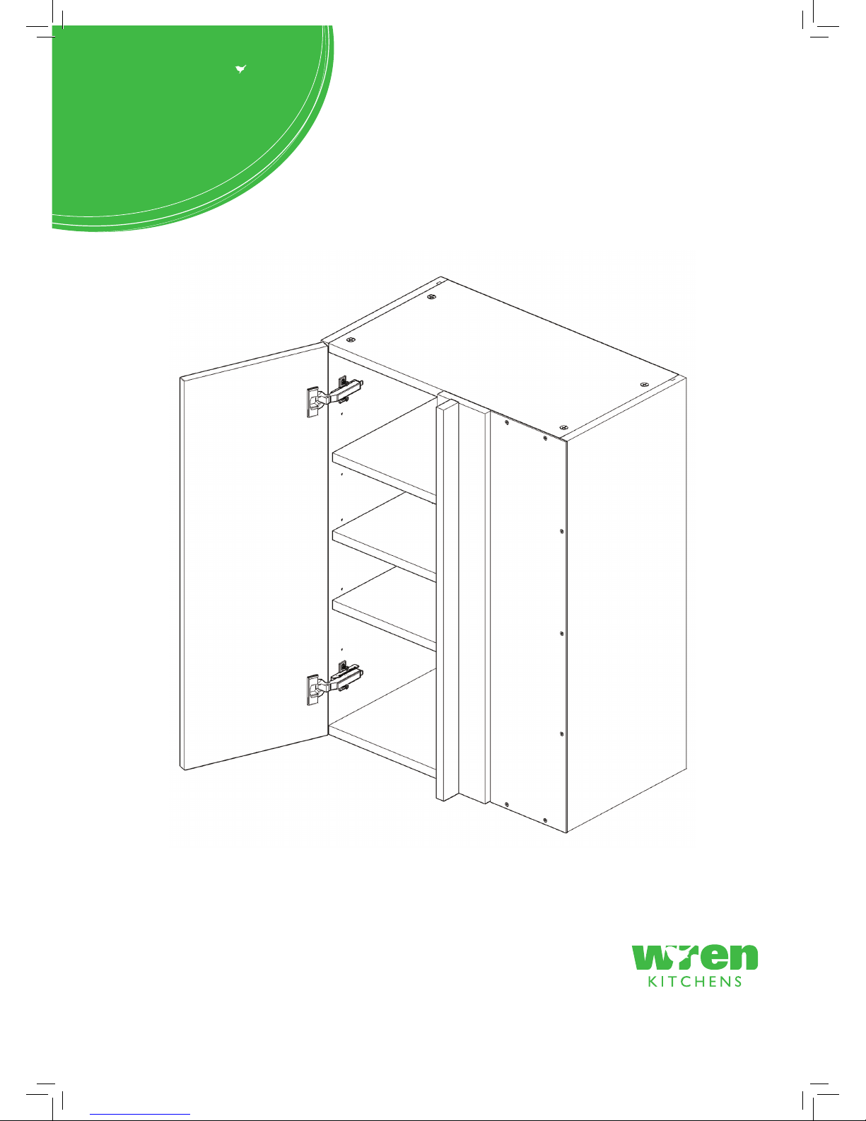
WALL UNIT
600 Tall Adjustable Corner
Assembly Guide
For Internal Use: FI.WR.INS.048_WKIN00133_WALL_600_Adj_Cnr_Tall_Rev2.indd
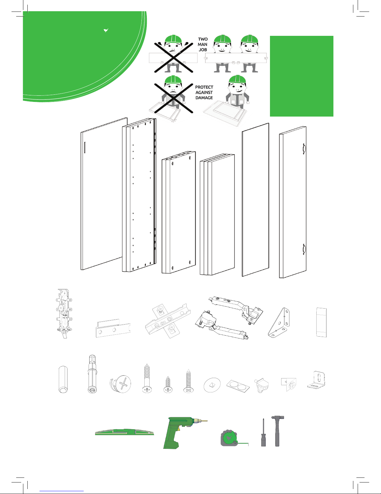
Hanging Bracket
X2 Inc Screws
Hanging Bracket Plate
X2 (Screws Not Included)
Hinge Mounting Plate
X2 Inc Screws
Hinge
X2 Inc Screws
Corner Gusset
X2
Hanging Bracket
Cover cap
x2
BEFORE YOU START
INSTALLATION
SHOULD BE
PERFORMED BY A
COMPETENT
PERSON ONLY.
THIS PRODUCT COULD
BE DANGEROUS
IF INCORRECTLY
INSTALLED
REQUIRED TOOLS
NOT to be used
with CAM DOWEL
& CAM LOCK
Panel B
x2 End Panel
Loose Shelf
x3
Blanking Panelx1Frontal (packed separately)
x1
Panel A
x1 Back Panel
Panel C
x2 Base Panel
(F) x8
Wooden Dowel
(G) x8
Cam Dowel
(Expanding)
(H) x8
Cam Lock
(K) x4
30mm
Screw
(L) x21
15mm
Screw
(S) x4
20mm
Screw
(M) x2
Cover Cap
(R) x2
L Bracket
(N) x1
Door
Buer
(O) x12
Shelf Peg
Plastic
(T) x10
Back Panel
Support Clip
View from underside
For Internal Use: FI.WR.INS.048_WKIN00133_WALL_600_Adj_Cnr_Tall_Rev2.indd
Page 1
WALL UNIT
600 Tall Adjustable Corner
Assembly Guide
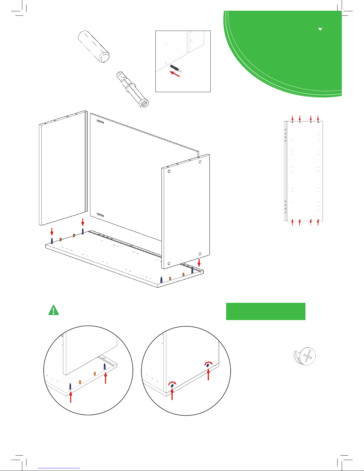
Step 1.
Seat dowel (F)
into holes in
both end panels (B)
as shown.
Step 2.
Seat cam dowel (G)
into holes in both end
panels (B) as shown.
Dowel (F)
& Cam Dowel (G)
Location Detail
Step 3.
Carcass construction
Attach panels x2 (C) to
panel (B), using cam
dowels (G) & cam locks
(H) (in blue), and also
using dowels (F)
(in orange) in positions
as shown.
All Cam Lock (H) are to be positioned facing
the outside of the unit carcass, for ease of tightening.
Step 5.
Insert cam lock (H). Hand
tighten all cam locks
(H), this will expand cam
dowels (G) and tighten the
unit together.
Seat (G)
cam dowel
into hole
as shown
Do not use power tools with
cam dowel (G) or cam lock (H)
C
C
A
B
Step 4.
Slide panel (A) into the
groove of panels (B) & (C).
G
G
F
FFFGG
B
B
C
H
H
G
G
View from underside View from underside
For Internal Use: FI.WR.INS.048_WKIN00133_WALL_600_Adj_Cnr_Tall_Rev2.indd
Page 2
WALL UNIT
600 Tall Adjustable Corner
Assembly Guide
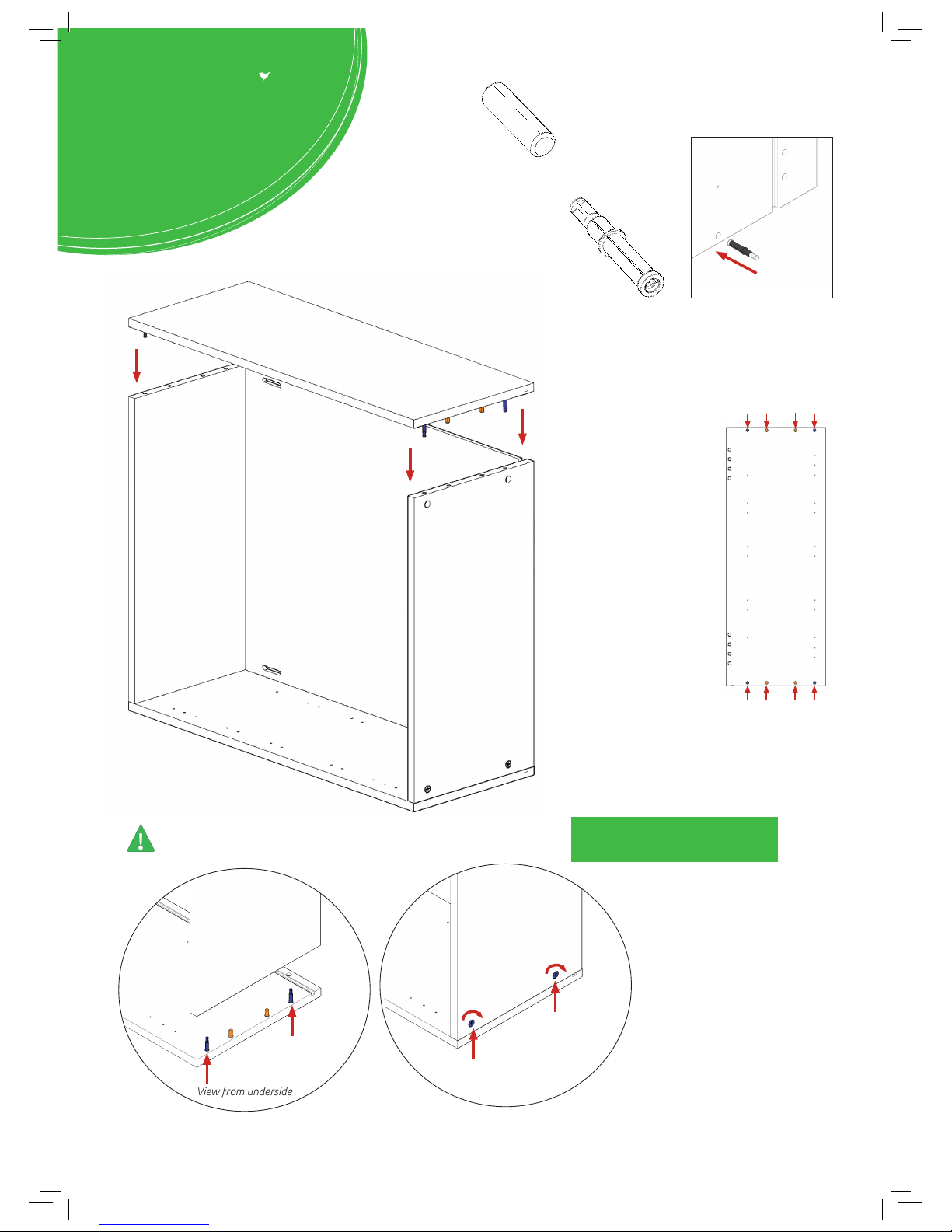
Step 8.
Carcass construction
Attach panel (B) to
panels (C) using cam
dowel (G) & cam lock (H)
(in blue), and also using
dowels (F) (in orange)
in positions as shown.
Ensure panel (A) is
seated into the groove of
panel (B).
All cam lock (H) are to be positioned facing
the outside of the unit carcass, for ease of tightening.
Do not use power tools with
cam dowel (G) or cam lock (H)
Step 9.
Cam lock (H)
Insert cam lock (H). Hand
tighten all cam locks (H), this
will expand cam dowels (G) and
tighten the unit together.
C
C
H
H
A
B
B
Step 6.
Seat dowel (F)
into holes in
both end panels (B)
as shown.
Step 7.
Seat cam dowel (G)
into holes in both end
panels (B) as shown.
Seat (G)
cam dowel
into hole
as shown
G
G
F
FFFGG
B
View from underside
View from underside
B
C
C
H
H
G
G
Dowel (F)
& Cam Dowel (G)
Location Detail
For Internal Use: FI.WR.INS.048_WKIN00133_WALL_600_Adj_Cnr_Tall_Rev2.indd
Page 3
WALL UNIT
600 Tall Adjustable Corner
Assembly Guide
 Loading...