

Operating Manual
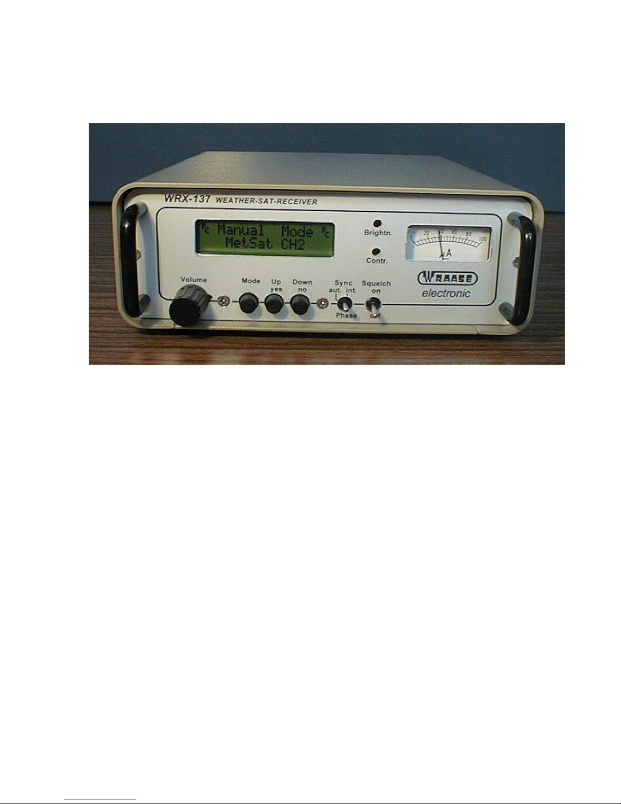
WRX-137 Weather Satellite Receiver
WRAASE electronic GmbH, Germany
General
The WRX-137 weather satellite receiver covers all polar orbiting weather satellites which
transmit in the analog APT mode. Beside the 5 fixed frequency channels any other frequency
between 134 and 141 MHz can be manually selected in 10kHz steps. Additional fixed
channels can be added by firmware-updates, if required. All modes and functions can be
manually selected by the front panel controls.
For unattended automatic operation and/or if the receiver shall be located at a remote location,
frequency selection can be remote controlled by software, either by the supplied program
"WRX137" or the actual satellite receive software “WxToImg” or Timestep “PROsat”. The
WRX-137 receiver can feed the PC sound input for use with any popular soundcard-based
APT satellite image decoding software like "WXTOIMG". For this, the rear panel audio
output supplies an especially filtered subcarrier output signal with constant, but adjustable
level, independent of the front panel volume control.
The WRX-137P also supports “PROsat” and “JVComm” decoding software with its built-in
microprocessor controlled APT decoder and serial RS232 data output. “PROsat” and
“JVComm” allow full multitasking (receive images while processing and displaying other
stored images and/or running other software). Soundcard based software often has none or
only very limited mulitasking capability and suffers under time- and memory-consuming
processing. The WRX-137 was originally designed to also receive the WEFAX signals from
geostationary satellites. Since this is obsolete now, the second “CONV.” marked BNC
connector is now used as a second input for passive VHF antennas (no DC on that socket).
1

CONNECTIONS AND SETUP
Power supply
Power requirement is 12 to 16 V DC @ 200 mA. Voltage stability is not critical because it is
internally stabilized.
If you do not use the supplied AC power supply, carefully check the correct polarity: Center
pin is (-) . The unit is fully protected against wrong power polarization: An internal fuse will
immediately blow. To reach the fuse for replacement you must remove the 4 screws on the
bottom and pull the chassis out of the main case. It is a standard 20mm radio fuse (250 to 500
mA).
Antenna Connection
It is strongly recommended to use a special weather satellite antenna with righthand circular
polarisation (KX-137 or MX-137). Only with such antennas an interruption-free satellite pass
and a coverage range of 4000 or more kilometers can be expected. If the antenna cable length
is in the range of 20 to 30 m, an antenna preamplifier may not be necessary. Our preamplifier
AA-137 or the active antennas KX-137 or MX-137, however, will in most cases improve
reception-quality and -range as well as immunity against strong terrestric signals because of the
integrated high-Q-filters and the extremely low-noise transistors.
In order to dc-supply a preamplifier or an active antenna without the need of an additional
cable, DC-voltage of 10 V is always present at the antenna input socket. This is not needed
when using the passive antenna model KX-137P but does on the other hand not represent a
problem. There exist, however, other antenna constructions which represent a DC-short-circuit
which would cause an immediate fuse-blow inside the receiver.
Antenna Considerations
As the satellites circulate in a polar orbit, the antenna should have a free line-of-sight at least to
north and south. Mounting the antenna under the roof is not recommended (althought in some
cases acceptable results are achieved). The height above ground is only critical with respect to
the lowest possible line-of-sight elevation angle to the horizon and possible reduction of the
shadowing effect of surrounding buildings. As a rule of thumb a line of sight to the horizon at
an elevation angle of 10 to 15 degrees is sufficient. This only applies for buildings, trees are
not so critical.
For good reception performance it is extremelyimportant that the antenna is mounted in a safe
distance to any possible radiation sources of broadband radio noise. Such sources of
interference are computers and all devices which contain microprocessors or switching power
supplies. The broad noise floor created by such devices (nowerdays most electrical household
equipment is suspicious) can easily cover the weak satellite signal. Noise reduction regulations
keep such noise low but do not eliminate it in a close distance. Keeping the antenna in a
distance of several meters from such devices will normally avoid such interference problems.
Connection to the PC
Received satellite data are output as analog audio throught the „AF OUT“ marked rear panel
socket and as digital serial data stream through the 9-pin D-sub connector “COMPUTER”.
2

OPERATION
START-UP OPERATIONS
After power is switched on, a welcome text will appear for a few seconds, indicating:
“WRAASE WRX-137” and the firmware version number.
The display then changes to show the question "PC control Yes / No?" . Press the " No"
button if you want to run the receiver in the manual mode only. If you want to allow the PC to
modify the receiver channels press "Yes" or just wait a few seconds and the PC-control mode
will be automatically loaded by default.
When PC Control is active, manualoperation is still possible, however frequency selections by
the PC software will have priority. The
P
C
symbol in the LCD indicates that the PC control
mode is active in the background.
MODES OF OPERATION
Press the “Mode” button to access one of the three possible general modes:
Manual Mode, AutoScanMode and ProgScanMode.
To confirm your selection, press the "Yes" button. Press the “Mode” button again to leave
the currently active mode and to start a new selection
Ø Manual Mode: The 5 fixed frequency channels can be selected one after the other by
pressing the "Up/Yes" button. Pressing the "Down/No" button activates the
manual frequency adjustment mode. “Down/No” and “Up/Yes” can then be used
to tune the receive frequency in 10 kHz steps. To leave this mode, press the
“Mode” button.
Ø AutoScan Mode: In AutoScanMode all the 5 fixed frequency channels will be
scanned and continuously checked for a satellite signal. As soon as the receiver
detects an APT signal, it remains on that channel as long as the signal persists and
scanning will continue as soon as it disappeares. As the receiver checks for the
presence of a subcarrier, scanning will only stop on true satellite signals and cannot
be disturbed by other signals. If the scanner has stopped on an unwanted satellite
frequency, you can at any time restart scanning by pressing the "Up/Yes" button.
The "Down/No” button has no function in the AutoScanMode.
Ø ProgScanMode: The ProgScanMode works equally to the AutoScanMode except
that scanning only takes places over certain preselected channels: After the
ProgScanMode is selected, all 5 available fixed frequency channels will be displayed
one after the other and you are asked to confirm them by either pressing "Yes" or
"No". Scanning will then start automatically after the last available channel is
confirmed with “Yes” or “No”. Your frequency selection will not be stored and has to
be renewed at any new call-up of the ProgScanMode.
3

PC CONTROL
PC-Control from Timestep PROsat software: Frequencies are assigned in the Auto Schedule
Options dialog box (right click into the tracking window). The list of available frequency
channels there contains two unassigned channles A and B. These are used for the new NOAA18 frequencies: select "A" for 137,100 and "B" for 137,9125 MHz. Don't forget to save your
settings by saving the associated tracking window and configuration.
Automatic frequency selection is also supported by the “WxToImg” software (ugraded
version only). Program configuration for this is in the “Options / Receive options” dialog box:
Select Receiver WRX-137 and Baudrate 57600.
If other software is used, which does not support automatic frequency selection, set the
WRX-137 into the AutoScanMode for automatic, unattended image reception.
The supplied program “WRX137.EXE” allows to modify the frequency and mode from a
Windows dialog box.
CONTRAST / BRIGHTNESS CONTROL (applies only for PROsat and JVComm)
When using the internal APT decoder and serial data output with PROsat or JVComm
software there is no need to do any contrast or brightness adjustments. All levels are internally
set by hardware for optimum image quality. Contrast enhancements and other image
processing can be done later by software. However, if any need occurs to slightly change these
hardware settings, there are two screwdriver operated controls available through the front
panel. Use the supplied "Spectrum" software to find the optimum settings. Note that data
transfer into PROsat or JVComm is interrupted as long as "Spectrum" is active (the serial port
can only be assigned to one program at a time).
Important note: The PROsat software provides several “level adjustment” controls and
functions. These were provided from Timestep for their old special hardware and are without
any function with the WRX-137 receiver.
Level adjustment for soundcard software. If soundcard software (WXtoIMG) shall be used,
connect the sound input of the computer to the “AF OUT” socket on the rear of the WRX-
137. The output level can be adjusted with the screwdriver operated control assigned
“LEVEL +/-“ Note that this control does not affect image data going out through the serial
port. It is possible to receive images at the same time with different software programs
throught the AF OUT and the serial data output.
SYNC MODES
(applies only for PROsat / JVComm serial data, not for soundcard software):
The “Sync”-switch has 3 positions: “Int.”, “aut.”, “Phase”.
For best results with the PROsat software keep this switch always in the middle position
(“aut.”) and set the synchronisation mode in the software to "Start Only". Note that this
setting has to be done individually for each satellite in the “Auto Schedule Options” dialog
4

Box! (The easiest way to reach this dialog is to click the right mouse button over the tracking
window.)
The technical background behind this is, that with the toggle switch in the middle position the
received signal will be generally synchronized from the satellite itself (dividing the subcarrier
frequency). This automatically compensates the doppler shift and the picture will not be
bended. On noisy signals however, when the subcarrier can not be detected properly,
synchronisation will automatically switch to the internal crystal clock and even noisy parts of
the image will be recorded, so that the grid and coastlines will always fit perfectly. In the up
position "int." synchronsation is always provided by the internal clock. This can be
advanteguous when receiving WEFAX from geostationary satellites.
The “Phase” position allows to manually phase the image in cases where the PC software has
failed to do so.
Important notes for operation with the PROsat software
Each time you start reception, PROsat requests a copy protection-key from the WRX-137
receiver. If the key is not received either a “Dongle not found” error message will appear or
the image information will be unreadable. Therefore it is important that the receiver is
connected and switched on before you start reception in the program. When the receiver
power is interrupted during reception, the key is invalidated and you have to start the
receiving mode in PROsat again.
In the case that the “Dongle not found” message is issued when reception is started, just
restart reception once again. In some cases it requires a second try before the copy protection
key is correctly read from the WRX-137.
When the system is first setup, it is stronly recommended to first use the simple Control Panel
Software “WRX137.EXE” to check proper operation of the receiver, proper connection and
comport selection. When “WRX137.EXE” works fine, close the WRX137.EXE-Window and
start PROsat (note that Windows allows only one program at a time to have conrol over the
serial comport).
PROsat still contains a lot of functions for the reception of geostationary satellites. As these
are obsolete, just neglect these functions and chapters in the manual and help file.
If you observe some strange horizontal image-shifting during reception (stepping), please
refer to the 2 pages of special notes “Stepping problem”. Such is caused by short
interruptions of the serial data stream and can in most cases be cured by switching off all the
Windows Power Saving Modes.
PROsat also works well with most standard USB to Serial converters.
Due to an internal Windows-problem, Windows sometimes interprets the dataflow from the
WRX-137 wrongly and installs an additional mousedriver, causing the cursor the jump around
like crazy. To avoid such problem, don’t have the WRX-137 connected or running when
booting Windows.
To get immediate results after software installation just start the supplied configuration
“NOAA_auto” and all active satellites will we recorded automatically.
5
 Loading...