

Page 1

UltraMicroPump II
UMP2 Microsyringe Injector and Micro4 Controller
INSTRUCTION MANUAL
Serial No._____________________
071807
World Precision Instruments, Inc.
Page 2

UltraMicroPump II
Contents
Introduction ...................................................................................... 1
Parts List ............................................................................................ 2
Set-up and Operation ........................................................................ 2
Setting Parameters ............................................................................ 6
UltraMicroPump II Operation ........................................................... 13
Defining Other Syringes .................................................................. 14
Computer Control ............................................................................ 18
General Maintenance ...................................................................... 25
Troubleshooting ............................................................................... 25
Specifications .................................................................................. 22
Syringes ........................................................................................... 23
Accessories, Replacement Parts .................................................... 24
References ...................................................................................... 27
Appendix: Nanoliter 2000 / Micro4 Volume Settings ....................... 28
Warranty .......................................................................................... 28
Copyright © 2006 by World Precision Instruments, Inc. All rights reserved. No part of this publication
may be reproduced or translated into any language, in any form, without prior written permission of
World Precision Instruments, Inc.
WORLD PRECISION INSTRUMENTS
31
Page 3
UltraMicroPump II
Introduction
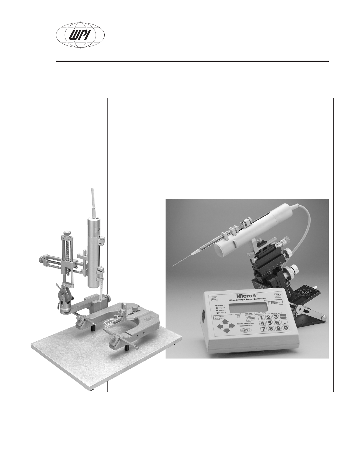
Thank you for purchasing WPI's UltraMicroPump II (UMP2) and the
microprocessor controller, Micro4™ (UMC4). This versatile injector uses
microsyringes to dispense nanoliter sample volumes. Microsyringes are easily
installed by placing the syringe barrel into the UltraMicroPump’s clamps.
UltraMicroPump accepts syringes from 0.5 µL to 250 µL.
UltraMicroPump can be useful for a wide range of applications including
intracellular injection, micro delivery of biochemical agents or dyes, cell
separation, in vitro fertilization, and can be mounted directly onto a stereotaxic
frame or micromanipulator.
WORLD PRECISION INSTRUMENTS
Fig. 1 — UltraMicroPump II and Micro4 controller. The pump above
is mounted on WPI’s M3301 micromanipulator and TB-1 stand (not
included); and syringe with luer µTip (not included). At left, pump is
shown with TAXIC900 stereotaxic frame (not included).
1
Page 4

UltraMicroPump II
Operating parameters for the UltraMicroPump are set with the Micro4. Up to four
pumps may be independently controlled. Operating parameters set by the user are
stored in “non-volatile” memory for instant recall when the unit is powered on.
An optional footswitch can be plugged into an RS232 port on the rear of the
controller for “hands free” start / stop operation. The same port may also be used to
connect the controller to a computer or to some other device for TTL triggering.
Parts List
After unpacking, make certain that there is no visible damage to the instrument.
Check to see that all items are included:
UMP2 UltraMicroPump II
UMC4 Micro4™ Controller, 4-Channel
40300 12-volt Power Supply
Power Cable
Allen key
Instruction Manual
For a list of microsyringes available from WPI, see page 23.
Set-up and Operation
These instructions will help you put the UltraMicroPump to immediate use. We
recommend that you read the entire manual and familiarize yourself with the
various operating procedures of the UltraMicroPump and Micro4.
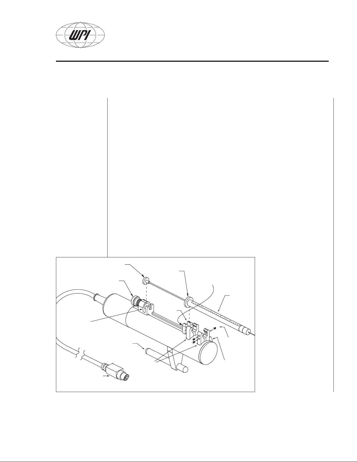
Mounting the syringe
Syringes may be filled manually before mounting in the UltraMicroPump or filled by
using the fast reverse function (see page 13). Place the plunger button of the filled
syringe into the plunger button holder (leaving the plunger retaining screw loose)
while also placing the syringe collar into the collar stop (see Fig. 2). Take care not
to damage the syringe collar during this installation. Gently tighten the plunger
retaining screw so that the plunger button will not move independently when the
pump is activated (this allows for zero volume error during pump operation).
WORLD PRECISION INSTRUMENTS
2
Page 5
UltraMicroPump II
MOUNTING BAR
COLLAR
STOP
SYRINGE
COLLAR
SET SCREW
(not visible in this view)
PLUNGER
RETAINING
SCREW
PLUNGER BUTTON
PLUNGER
BUTTON
HOLDER
CABLE CONNECTS
TO REAR PANEL OF
MICRO4 CONTROLLER
SYRINGE
CLAMPS
CLAMP
RELEASE
SET
SCREWS
SYRINGE
1
2
3
Axial Needle Alignment
In order to maintain a good syringe needle alignment particularly along the same
axis of the supporting bar, rotate the syringe body while placing in the two clamps
to allow the syringe to seat properly and align along the body of the pump for
minimal slant offset. If the clamp which holds the syringe collar (see “collar stop”
in the drawing below) is too tight or too loose, syringe needle alignment may be off
because of stress.
If the collar stop is too tight to allow the syringe collar to insert easily, then follow
these instructions:
Immediately below and behind the collar stop, in the groove where the long drive
screw is, there is a small Phillips head screw, attached to the collar stop. Loosen
this screw to slightly (about 0.5 to 1 mm) to allow for a thicker collar (see Fig 2).
You may have to grasp the collar stop and wiggle it backwards to move it. Once
the stop is backed out; check and adjust for a tight fit so the syringe body doesn’t
move when placed into the holder. Gently re-tighten the screw in the new position.
Fig. 2 — Initial syringe clamp adjustment — Secure syringe by sequentially
adjusting set screws with supplied Allen key: 1 for horizontal alignment, 2 for
vertical alignment, and 3 to eliminate play.
Note: you may have to retract the plunger button holder to get access to the setscrew.
Mount the pump
The UltraMicroPump can
be mounted directly onto
a stereotaxic frame or a
micromanipulator, using
the mounting bar (see
Fig. 2). The mounting bar
may be unscrewed and
modified by the user, if
necessary.
WORLD PRECISION INSTRUMENTS
3
Page 6
UltraMicroPump II
SWITCH
FOOT
RS232/
+12VDC IN
4
32
POWER ON
1
OFF
OUTPUT
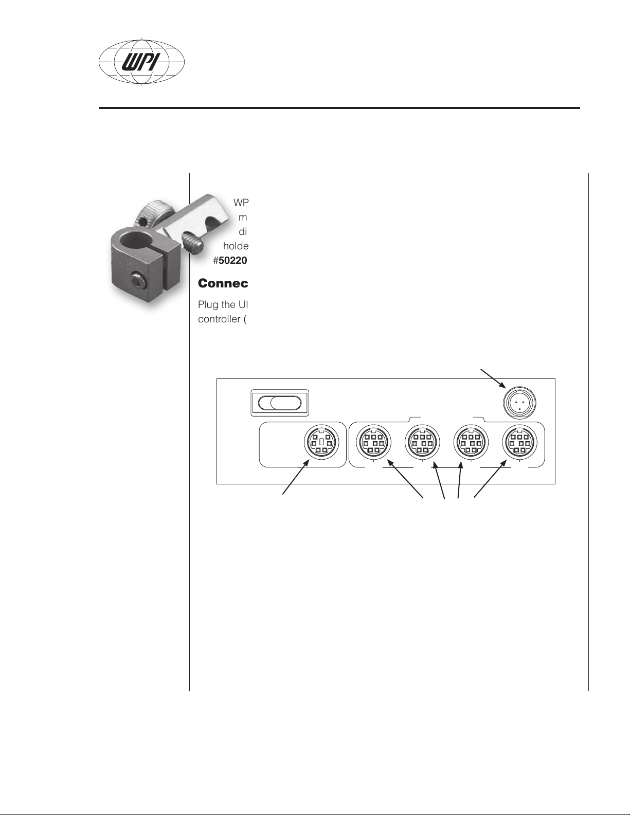
Mounting to Stereotaxic Frames
WPI’s UMP2 fits directly into most standard stereotaxic frames. The UMP2
mounting bar diameter is 7.90 mm (0.311 in.). For example, UMP2 fits
directly into Kopf Standard 900 series frames (in place of 1770 electrode
holder). Stoelting #51681 V-clamp adaptor / probe holder attachment (WPI
#502201, at left) required for use with Stoelting frames.
Connect the controller
Plug the UltraMicroPump cable into an output socket on the back of the Micro4
controller (see Fig. 3). Up to four pumps may be connected and independently
controlled.
Plug in the 12-volt power
supply.
Fig. 3 — Micro4
rear panel
Footswitch or RS232 cable from
computer plugs into this port.
Plug in the 12-volt power supply and power up
Plug the 12-volt power supply into the rear panel of the Micro4 (see Fig. 3). The
switchable power supply included with this unit automatically senses input line
voltage between 100 and 240 V and converts it to 12 V. Connect the power cord
to the power supply and plug it into an electrical outlet. The power switch is also
located on the rear panel of the Micro4.
Switch the Micro4 on and check that the LCD screen is illuminated.
The hardware setup is now complete. Before operating the UltraMicroPump you
must enter the parameters into the Micro4 controller.
WORLD PRECISION INSTRUMENTS
Connect up to four
UltraMicroPumps.
4
Page 7

UltraMicroPump II
Choosing a Syringe
The syringe should be chosen to inject no less than 5% of the volume of any given
syringe.
Example: A 100 µL syringe may be used for injections on the UMPII to volumes of
5 µL (5000 nL) and higher with high precision and repeatability. Expecting this 100
µL syringe to inject lower than 1 µL may be difficult if the syringe is not calibrated
specifically on the pump. The overall accuracy of the syringe itself is usually no
greater than +/-3% and the syringe internal diameter may deviate from location to
location along the length of the syringe interior.
Choosing the correct syringe for an injection is a very important consideration,
due to accumulated errors of the syringe and the pumping method. For a 1000 nL
injection from a 10 µL (10,000 nL) syringe, the user is asking for a 1/10th the
syringe’s volume value to be injected. Theoretically, based on mathematics without
any consideration to surface tension, heat, pressure, compressibility, silanization,
or air bubbles, the 3% error rate should yield a ± 300 nL variance.
As a rule of thumb, the choice of the syringe should not exceed 1/10th to 1/20th the
stated full volume of the syringe. The Micro4-UMP2 system uses a stepper motor
to move the syringe piston forward to inject the volume. A consideration should
also be made to allow the motor to step forward a good number of steps to prevent
errors in volume injecting.
Example: In the 10 µL case above, a 1-step movement of the motor will inject
a volume of 0.5276 nL. For two steps to occur, a volume of 1.055 nL will be
injected. This may or may not be acceptable as the total error may exceed 1
nL or nearly 0.1%. Also note that two steps is probably not enough resolution to
accurately control the volume; another rule of thumb would be to step no less than
10-100 steps for the entire single injection. Using this 10-step rule, the minimum
acceptable injectable volume from this 10 µL (10,000 nL) syringe would be
0.527.6 nL × 10 or 5.276 nL. Other syringes will give other results, due to the inside
diameter and the volume per step.
WORLD PRECISION INSTRUMENTS
5
Page 8
UltraMicroPump II
G = Grouped
N = Non-grouped
D = Disabled
World Precision
Instruments
MicroSyringe Pump Controller
Output 1
Output 2
Output 3
Output 4
VOLUME
SET
(nl)
VOLUME
COUNTER
(nl)
RATE
DEVICE TYPE
123
456
789.0
SELECT
DATA
SAVE
RUN
STOP
I=Infuse
W=Withdraw
TM
S=nl/sec
M=nl/min
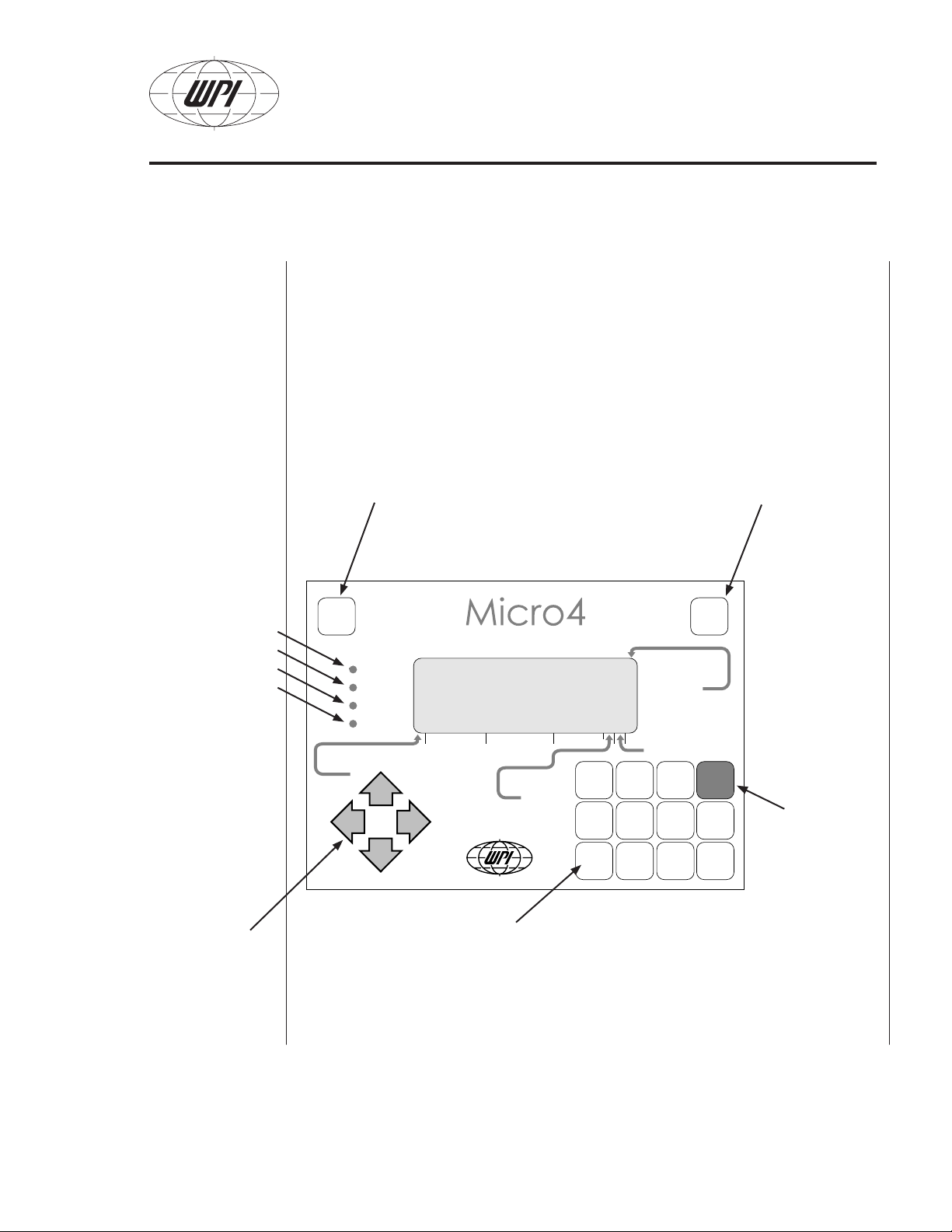
Setting Parameters
Parameters are entered using the membrane keys on the front panel of the Micro4.
The l e f t and r i g h t a r r o w keys move the cursor on the LCD display to the desired
position. The u p and d o w n a r r o w keys select the channel (corresponding to the
output channels on the rear of the instrument). The n u m b e r keys and the s e l e c t
key are used to change parameters.
Fig. 4 — Micro4
front panel
Lights: When a
pump is running,
the corresponding light is on. For
example, the light
next to output 1 will
be on when pump
one is operating.
Arrow keys:
Move the cursor
around the display.
WORLD PRECISION INSTRUMENTS
Data Save: Saves all parameters on LCD display
to memory. Next time the Ultra Microsyringe Pump
controller is turned on, the last paramaters saved will
be displayed.
Numeric keypad: Use these keys to
enter settings for infusion and withdrawal
rates and volumes.
Run/Stop: Starts
and stops the
pump(s).
Select: Toggles
the selected
parameters: Infuse/
Withdraw, Syringe
Size, Rate Units
(nL/sec or nL/min),
and mode (Grouped,
Non-grouped and
Disabled).
6
Page 9
UltraMicroPump II
I = Infuse
W = Withdraw
# = Option
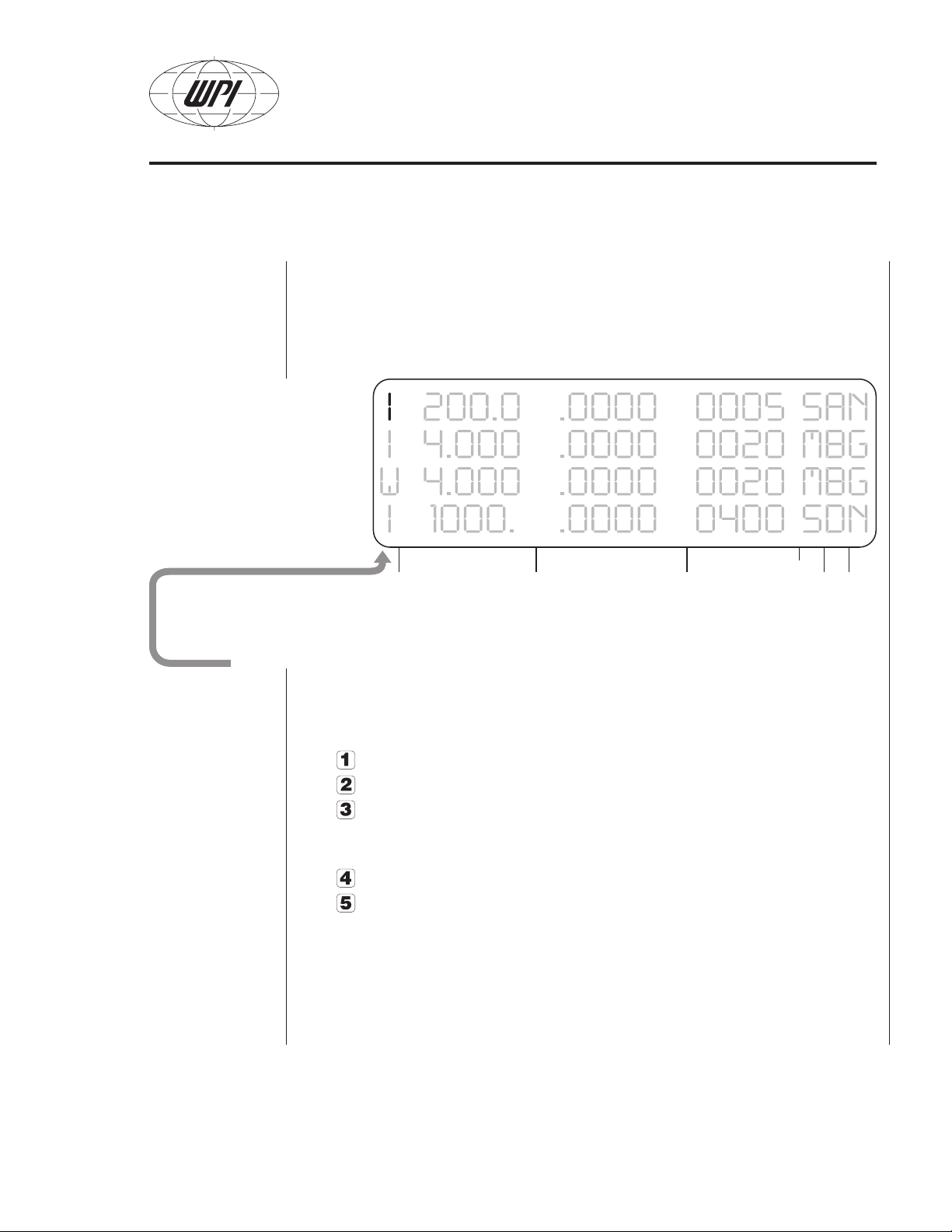
Setting Infuse/Withdraw
The character displayed in the first field indicates the operating mode — I for
Infuse, W for Withdraw. To change modes, use the a r r o w k e y s to position the
cursor in this field, then press s e l e c t .
In addition, the options below may be enabled or disabled when the cursor is in
the Infuse/Withdraw field: position the cursor in the Infuse/Withdraw field and press
the corresponding option number.
Disables audible tone.
Enables audible tone.
Changes the action of r u n /s t o p key or footswitch. When this option is
enabled the pump will operate as long as the r u n /s t o p key or footswitch is
pressed and stop when the r u n /s t o p key or footswitch is released.
Returns r u n /s t o p key or footswitch to normal operation.
Sets Volume per Step for syringe types not already preset in the Micro4’s
memory (see page 14).
WORLD PRECISION INSTRUMENTS
7
Page 10
UltraMicroPump II
VOLUME
SET
(nL)
VOLUME
COUNTER
(nL)
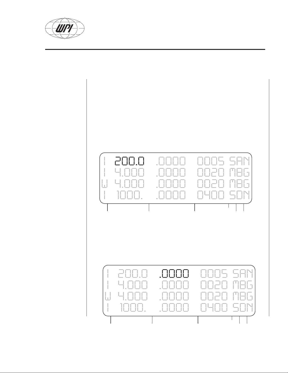
Volume Set
To select the desired volume to be infused or withdrawn, position the cursor in
the volume set field and enter the numbers with the numeric keypad. The values
shown on the LCD display are in nanoliters. (Note: For 10 µL enter “10000”; for
1.0 µL enter “1000.”—including decimal point.)
Syringe Injection Accuracy: Since every syringe in the microliter volume range
has its own unique intricacies, you should verify and calibrate each syringe and log
its characteristics for accurate injections. The Micro4 controller has preset types
of syringes to very accurately move the plunger button of the syringe a precise
distance per injection.
Volume Counter
Real-time display of volume being delivered. When pump is not running, this
number may be changed; when pump is restarted, counter will continue from the
number entered.
WORLD PRECISION INSTRUMENTS
8
Page 11

UltraMicroPump II
RATE
Injections beyond 99,999 nL (5 digits in the volume field)
Example: You want to inject 150,000 nL from a 500 µL liquid tight syringe, but the
volume counter can not accept 150,000 as a number.
1. Take the value 150000 / 500000 = 0.3 or 30% of the syringe volume.
2. Use a syringe TYPE that can accommodate a proportionally reduced number
of the same injection percentage (in this case 50%).
3. Using TYPE H, a 250 µL syringe as the choice a 75,000 nL injection is
equivalent to a 150,000 nL injection in a 500 µL syringe.
4. Multiply times 60 mm for the actual distance travel 0.3 × 60 = 18 mm (60 mm is
the full volume stroke of the syringe).
5. Check: 75,000 / 250,000 = 0.3; 0.3 × 60 mm = 18 mm.
6. Any combination of syringe types and volume choices can be used to displace
a particular length, as long as the volume is noted and the injection speed
does not exceed the rated value nearest that syringe volume. See syringe
tables, page 11.
Rate setting / unit time
To select the rate for infusion or withdrawal, position the cursor in this field and type
in the desired value with the numeric keypad. If the rate entered is too large for
the selected syringe type, the highest possible value will be displayed in this field.
Next, select the rate units.
WORLD PRECISION INSTRUMENTS
9
Page 12

UltraMicroPump II
S = nl/sec
M = nl/min
DEVICE TYPE
Rate Units
Two rate units are available — nanoliters per second and nanoliters per minute.
Position the cursor in this field and use the s e l e c t key to choose either S (nL/sec)
or M (nL/min).
Device (syringe) Type
The volume per step and rate data for eleven microsyringes are already stored in
Micro4’s memory. To specify one of these syringes, position the cursor in this field
and use the s e l e c t key to change the syringe type to a letter (A - L) corresponding to that of the syringe in the table below.
WORLD PRECISION INSTRUMENTS
10
Page 13

UltraMicroPump II
Type
A
B
C**
D
E
F
G
H
I
J
K
L
M
**
Syringe Volume
(Defined for this length)
0.5 µL (54.1 mm)
1.0 µL (54.1 mm)
5 µL (54.1 mm)
10 µL (54.1 mm)
25 µL (60.0 mm) 0.73 1.329 1022
50 µL (60.0 mm) 1.03 2.646 2035
100 µL (60.0 mm) 1.46 5.315 4088
250 µL* (60.0 mm) 2.3 13.191 9999
500 µL* (60.0 mm) 3.26 26.501 9999
1000 µL* (60.0 mm) 4.61 52.995 9999
Nanoliter 2000
10 µL (60 mm) 0.4607 (0.100 Rev H) 0.5293 (0.0249 Rev H) 170
User Defined See page 12
ILS005 (27 mm) 0.4856
†
†
†
†
† †
* Gas-tight syringes are not recommended for UMPII in these volumes; instead, use a liquid-tight
syringe to prevent drive motor damage.
** The ILS005 5 µL syringe must use type M with a 0.5880 nL / step entry. See page 15 for details.
† These are defined as 60 mm in Rev. H firmware.
† † WPI’s Nanoliter 2000, a nanoliter injector for the 2-70 nL range, comes with its own simple controller
but may also be driven by the Micro4. For more information, enquire about WPI # B203XVY.
0.1085 (0.102 REV H) 0.0294 ( 0.026 Rev H) 20
0.1534 (0.145 REVH) 0.0587 (0.052Rev H) 40
0.343 (0.325 REV H) 0.2934 (0.263 Rev H) 202
0.485 (0.46 REV H) 0.5868 (0.528 Rev H) 406
0.48 plunger in 0.50 glass 2.3 nL /step (0.0005” step) 884
ID (mm) nL / step REV J
0.5880 compensates for length as
TYPE M
Max. Rate
nL /sec or
nL /min
Note On Syringe Stroke Length
The delivery of the UMPII is based on 60 mm or 54.1 mm syringes. Please note
which syringe length you are using as a factor of 0.9016 may need to be applied to
Maker Syringe
Hamilton 1700 Series ,10 µL 60 mm
Hamilton 700 Series,10 µL 54.1 mm
SGE 0.5 µL – 10 µL 54.1 mm
ILS 5 µL Luer tip ILS005 28 mm
SGE 25 µL – 500 µL 60 mm
WPI FlexiFil™ 54.1 mm
WPI NanoFil™ 60 mm
WORLD PRECISION INSTRUMENTS
Stroke
Length
Use TYPE
L
D
A,B,C,D
M
E - L
D
L
the volume to be injected in order to have a precise injection.
For the ILS005, use the TYPE
“M” values in the above table.
*Manufacturers have the right to
change this specification at any time.
11
Page 14

UltraMicroPump II
G = Grouped
N = Non-grouped
D = Disabled
(blank)
Grouped/Non-grouped/Disabled
For convenience in operating multiple pumps (whether of identical or various volumes), pumps may be grouped or non-grouped. Pressing the s e l e c t key while the
cursor is in this field will toggle through three operating modes:
Grouped mode: Syringe channels with “G” in this field are started or
stopped when the r u n /s t o p key is pressed while the cursor is located on any
grouped channel.
Non-grouped mode: When the cursor is positioned on a channel that is
not grouped, indicated by the letter “N”, only that channel will start or stop
when the r u n /s t o p key is pressed.
Disabled mode: When a channel is disabled, the line of data is hidden and
the pump will not operate. No changes may be made to this channel while
it is disabled. To re-enable it, move the cursor back to the Group/Nongroup
field and press the s e l e c t key; the previously entered data will be restored.
Saving your settings
Pressing the button will store these values into the controller’s memory for
future use.
WORLD PRECISION INSTRUMENTS
12
Page 15

UltraMicroPump II
UltraMicroPump II Operation
When the pump runs, a series of beeps indicates that the pump is running. At
the end of the program, the controller also beeps. A lamp on the back of the
UltraMicroPump indicates a signal from the controller. As the pump runs, the
counter increments as an indication of the plunger’s motion. Multiple injections can
be achieved by pressing the r u n /s t o p button again after the pump has stopped.
Fast forward
Press and hold the r i g h t a r r o w key then press r u n /s t o p . The syringe
pump will continue running as long as these two keys are depressed or until the
set volume is reached.
Fast reverse
Press and hold the l e f t a r r o w key then press r u n /s t o p . The syringe
pump will continue running as long as these two keys are depressed or until the
set volume is reached..
WORLD PRECISION INSTRUMENTS
13
Page 16

Calculate in Microsoft
Excel — just enter
these formulae into
a spreadsheet,
replacing Volume,
Length, and ID
from your own
measurements.
UltraMicroPump II
Defining Other Syringes
Eleven microsyringes with volumes ranging from 0.5 µL to 1000 µL are already
preset in the Micro4 (syringe types A through L — see table on page 11). A microsyringe with a volume other than those preset may be entered as device type
M. However, the Volume per Step of the type M syringe must be defined for the
Micro4. NOTE: There is only one memory location to define a Type M value for all
four pumps.
First, calculate the Volume per Step using the formula below. Syringe displacement is the distance between 0 and the maximum volume marked on the syringe in
inches. Syringe volume is in nanoliters. ID is in millimeters.
Syringe of known ID
Volume per Step = (ID/2) x (ID/2) x 3.1415926 x 1000 x 0.003175
Syringe of unknown ID
The Inside Diameter (ID) of a syringe can be determined by this formula:
ID = SQRT(Volume/(3.14159 x Length)) x 2
where length is the visible marking on the syringe body (total length in mm) and
Volume is the full volume of the syringe in microliters.
For example, if you have a 60 mm syringe with a
2.5 µL volume, use the formula above to determine
its Volume per Step. Move the cursor to the Volume
Set field of output channel 1 and enter the calculated
value (in this case, 0.1323 nL):
Then use the l e f t a r r o w key to scroll the cursor to the
first position on the LCD display and press . This sets your calculated definition
for your type M syringe into the Micro4’s memory.
WORLD PRECISION INSTRUMENTS
14
Page 17

UltraMicroPump II
Note that this does not yet affect the action of any channel since M has not been
selected as the device type for any channel. Before proceeding, move the cursor back to the Volume Set field and re-enter the correct volume for the syringe on
output channel 1 (which may be any type — not necessarily type M).
Special Syringe Considerations ILS005
The UMPII-Micro4 was designed around 60 mm or 54.1mm syringes. The full
injection of a 5 µL syringe is expected to be a 60 mm movement. In the case of this
ILS special 5 µL glass luer tip syringe this length is 27 mm for an injection of 5 µL.
There are two solutions:
Solution 1. Using Type “C” (the 54.1 mm 5 µL syringe), Multiply the volume
to be injected by 27/54.1 or (0.4990).
Example. A 2500 nL injection using type C should be entered into the micro4
as 2500 × 0.4990 or 1247.5 nL. this value can be further calibrated see page
17 for details.
Solution 2. Using Type M, divide the Type C nL/step number by 0.4990.
Example: The standard 54.1 mm syringe has a value of 0.2934 nL/step on
a 5 µL syringe. The ILS005 has a 27mm stroke for this same full volume.
0.2934 / 0.4990 = 0.5880 is the nL / step value to enter following the Type
M instructions on this page. (0.5880 is also verified by the formulas on the
previous page.)
After defining your syringe in Micro4’s memory, move the cursor to the Device Type
field of the output channel to which that pump is connected and press s e l e c t until
M appears.
Any number of channels may use type M syringes, but
since a single definition for type M is stored in Micro4 all
M devices must be identical. (That is, you cannot use
two non-standard types, such as 2.5 µL and 0.25 µL.)
The minimum delivered volume depends on the syringe
size and is listed in the syringe type table under Volume
per Step. The actual volume delivered is divisible by the volume per step. For
example, using a syringe with a Volume per Step of 1 nL, actual delivered volume
for the given set volume is listed below.
WORLD PRECISION INSTRUMENTS
15
Page 18

UltraMicroPump II
Volume Set Actual volume delivered
0-0.9999 nL 0
1 nL-1.999 nL 1 nL
2 nL-2.999 nL 2 nL
and so on...
Using Teflon Tipped syringes
Carefully remove the plunger and its Teflon tip by drawing it out of the syringe
barrel.
1. Before inserting the plunger tip into the syringe, pre-wet the Teflon plunger tip
and the syringe body interior with water.
2. Use care in inserting the plunger into the syringe as the plunger rod may be
easily bent.
3. Carefully place the plunger tip into the syringe and gently work the tip down
into the body of the syringe using a thumb and forefinger to grasp and push
small lengths of the plunger rod into the syringe. Repeat this procedure until the
plunger tip is near the zero mark of the syringe.
4. Draw additional water into the syringe and slowly work the plunger up and down
until the plunger tip is cold formed into the syringe and the stiffness goes away.
The stiffness of the new plunger tip may require you to move the rod in small
increments until the tip is formed enough to actuate by the rods full length.
Wet Autoclaving Syringes
Typically the answer to autoclaving any Teflon syringe is no, since the adhesives
and the Teflon seal will eventually breakdown or swell from the heat and pressures
involved. The most practical method of sterilizing is either gas or liquid chemical
sterilization, but both require meticulous removal of the sterilizing agents prior to use.
If you are willing to replace the syringe after a few uses then most syringes will
stand up to a few cycles of wet autoclaving. The Teflon tipped plunger should be
removed for this operation. Careful examination of any glued components and the
Teflon tip integrity is required before reuse of an autoclaved syringe. If the Teflon tip
cannot be replaced into the syringe body easily then the plunger (tip) and perhaps
the syringe requires replacement due to infusion of water. Autoclaving will usually
void the warranty on Teflon tipped syringes.
WORLD PRECISION INSTRUMENTS
16
Page 19

UltraMicroPump II
Calibration
Every syringe should be calibrated on the pump that it is being used with.
This gives the user two things, verification of the error involved in the injection and
the confidence that injection is correct. Micro volume syringes are rated at 1% to
3% of the full-scale volume. So for a 10 µL syringe injecting 10 µL there will be a
maximum error of ± 0.3 µL if the injection takes place along the markings on the
syringe barrel. When used in a specialized syringe pump like the UMPII, this same
syringe is now defined by a fixed length and moved by a precision stepper motor.
This can offer a very high degree of precision and repeatability. This same 3% error
10 µL syringe can now be calibrated to deliver a reduced error of ± 0.5% tolerance
or better.
Two methods of calibration
Calculate in Microsoft
Excel — just enter
these formulae into
a spreadsheet,
replacing Volume,
Length, and ID
from your own
measurements.
Volumetric diameter measurement
Using a microscope and a calibrated reticle or stage micrometer, inject an
amount of water into a hydrated oil droplet, measure the sphere and use
Volume = ((Diam/2) × (Diam/2) × (Diam/2) × 3.1415926 × (4/3) × 1000))
to determine the volume in nanoliters. (Diameter in mm.)
Analytical Balance
Use an analytical balance to weigh the mass of the injected volume. (Pure
water is 1 gm = 1 mL at 4 degrees C.) Tables for other temperatures are
easily obtained.
Calibration on the Pump
Method 1: Multiply the ratio of the injected volume by the actual volume and
adjust the volume injected accordingly.
Method 2 : Use the TYPE M syringe and enter the new nl/sec number after
recalculation.
Note: It may be necessary with some syringes to verify injections at different
locations along the length of the syringe barrel as there can be variations along the
inside length of the glass barrel.
WORLD PRECISION INSTRUMENTS
17
Page 20

UltraMicroPump II
Computer Control
RS232 commands are used to control the Micro4 via the serial port of a PC or
Macintosh computer.
RS232 Commands
All commands are case sensitive. The settings for the RS232 port are baud rate
9600, 8 data bits, 1 start bit, 1 stop bit. Microsoft HyperTerminal setting: Flow control must be set to NONE.
Numbers and decimal points are indicated below by the “#” symbol.
V######; Sets the delivered volume. Number must have a decimal point and
terminate with “;” (semicolon) — see page 19.
C######; Sets the volume counter. Number must have a decimal point and
terminate with “;” (semicolon) — see page 19.
R####; Sets the delivery rate. Number must have a decimal point and
terminate with “;” (semicolon) — see page 19.
I Infuse mode.
W Withdraw mode.
G Go — Starts the syringe pump.
H Halt — Stops the syringe pump.
S Sets the rate units to nanoliters/second.
M Sets the rate units to nanoliters/minute.
L#; Line number — sets the syringe number on display (Micro4 only).
N Not Grouped mode.
P Grouped mode.
D Disabled mode.
Tx Syringe Type. The letter indicating syringe type follows the T. For
example, to select syringe type “A” the command is “TA”.
RS232 Query Commands
All query commands begin with a question mark. Below is a list of the query
commands.
?V Returns the set volume.
?C Returns the volume counter
?R Returns the delivery rate
WORLD PRECISION INSTRUMENTS
18
Page 21

UltraMicroPump II
?M Returns a G for grouped mode, N for nongrouped mode, and D for
disabled mode.
?S Returns the letter of the syringe type.
?D Returns the syringe pump direction: I=infuse, W=Withdraw.
?U Returns the rate units: S=nL/second, M=nL/minute.
?G Returns a R if pump is running, S if pump is stopped.
TROUBLESHOOTING RS232 Commands
The correct format in relation with a specific command sent is as follows:
There is no set sequence to follow when issuing commands, but for logical
programming purposes, follow the following sequence: L1;IV100.0;C0.0;R200.0;ST
FN
Note there are no spaces, line feeds or enters (carriage returns). The CR does not
interfere.
The V, R and C parameters require a “.” (decimal point) and the character “;”
(semi-colon) to be entered.
You should immediately see a response on the UMC4 display from each entry as it
is entered.
The cursor channel indicator (the L#; command) must be on the pump channel
that is being run. If the cursor is elsewhere, then the command will not function on
other channels unless the grouping is turned on (G last column).
Format of the V volume command
The character field of V is a maximum of five numerals; a 6th character can be the
period (.) There is no requirement for a zero to the right of the decimal point. One
could enter V12345.; and see the result echo by typing ?V and getting 12345 on
the display. The channel selected will show 12345 on the UMC4 display as soon as
the “;” character is typed.
Format of the R rate command
The character field of R is a maximum of four numerals; a 5th character can be the
decimal point (.). You cannot override the maximum number for the syringe type.
Example: Type A is a 0.5 µL syringe and has a maximum rate of 20 nL/sec. Typing
in a greater number will still give you the maximum rate of 20 nL/sec.
WORLD PRECISION INSTRUMENTS
19
Page 22

UltraMicroPump II
Format of the C counter command
The character field of C is a maximum of five numerals; a 6th character can be the
decimal point (.).
This field should be entered as C0.0; to begin with as this is the counter that
determines how much more the sryinge needs to move before it stops. Note:
Resetting this field to 0; may be required in certain conditions.
The Micro4 Controller echos the follwing if issued the preceeding command
V123.4; will give 123.40
V12.34; will give 12.340
V12.; will give 12.000
C1234; = 12340
C1234.; = 1234.0
R100.0; = 0020. (TYPE A rate restriction)
R1000.; = 1000. (Using type F, 2035 maximum rate)
R1000.1; = 1000.
V120; will yield 12000. since the decimal point was not entered.
Display not showing programmed values
If the volume and the rate cannot immediately be seen on the Micro4 display, this
could be due to the Grouping being turned off; the programmed units display
comes up immediately on acceptace of the “;” transmission.
The first item to test is the line number command and see that the cursor moves to
the line and blinks.
When the final character “;” is entered then the display will change, if it does not,
then apply a hard reset. (Power off then on and try again). All the parameters need
to be entered for the pump to act accordingly; blank fields are unknowns (most
likely a previously stored condition).
Non-grouped Dispensing
The pump channel where cursor is blinking is the only active program line that
WORLD PRECISION INSTRUMENTS
20
Page 23

UltraMicroPump II
1
2
3
4
5
6
will activate. The way to run multiple lines is to run them grouped or run them
by separate commands after the line number is changed to that channel. The
channels in this latter case are completely independent from each other (nongrouped).
Incorrect Volume Dispensed
The amount of volume actually dispensed was what was programmed in on a prior
programmed instance. To correct this, reset the counter, specify the C parameter
as “C0.0;” with the Volume and Rate on a separate command line, just before
issuing the G (go) command.
RS232 Cable Pinouts
To control the Micro4 by computer, the RS232 cable must be configured as shown
here:
Mini-DIN connector
on rear panel of
Micro4 controller
Micro4 cable with 9pin connector is WPI
#40500.
Signal Micro4
Mini-DIN
Ground 1 5 7
UMC Data IN 2 3 2
UMC Data OUT 5 2 3
Run/ Stop 4 - -
+5V pull up 6 - -
9-Pin
D-sub
25-Pin
D-sub
Footswitch Connections
Since the footswitch produces Run and Stop signals by connecting +5 volts (from
pin 4) to pin 6, this port may also be used for TTL signals from other sources.
WORLD PRECISION INSTRUMENTS
21
Page 24

UltraMicroPump II
General Maintenance
UltraMicroPump requires minimal maintenance; regular laboratory cleaning will
keep this instrument in optimum operating condition.
Do not apply solvents or oils to any part of the UltraMicroPump.
This instrument is not autoclavable.
Do not disassemble—there are no serviceable parts inside either the UMPII or the
Micro 4 controller.
Always hold UltraMicroPump by the main body or mounting bar. Do not swing or
carry the UltraMicroPump by its cable.
Storage:
Store the UMPII in a sealed plastic zip bag to prevent dust from accumulating on
the drive screw. Excessive dust can cause jams and inadvertent stops.
Use of gas-tight syringes on the UMPII is not recommended for syringes above
250 µL as this can damage the motor. Please use liquid-tight syringes for
applications that require volumes greater than 250 µL.
Troubleshooting
Problem: The instrument motor makes noise but the plunger button does not travel.
Check: Look for a loose connector at the rear of the Micro4, make sure the UMPII
plug is firmly seated. The gray plastic plug should be a flush fit with the connector
on the controller. Verify that the pins in the connector are not damaged.
Check: Test the pump in another channel, with the same program parameters.
Instrument Overtravel
If the plunger button has traveled to the extreme edge of the pump and has
jammed, try the following procedure to free the plunger button:
Place the pump so that the syringe would be pointing to the right (no syringe
should be in the pump). Program the Micro4 to Syringe style F (or larger to H),
program in about 2000 to 5000 nL in the volume and program in a rate of 2000 or
greater (there are internal limits). Press and hold the Right or left arrow key for the
WORLD PRECISION INSTRUMENTS
22
Page 25

UltraMicroPump II
direction you want the plunger holder to move in and quickly tap the RUN/STOP
key a couple of times to unwind the tension on the drive screw and move the
plunger holder away from the end of its travel. If the holder cannot be moved away
from the stop end easily by this method, then contact techsupport@wpiinc.com
for assistance. The pump may have to be returned for mechanical disassembly to
correct this.
Stalling
The UMP2 may stall for a number of reasons. The most likely cause is that the
pump motor cannot push the syringe plunger for the following reasons:
1. More than 400 g is required to push the syringe plunger. The syringe should not
be a gas-tight (i.e., Teflon-sealed) piston greater than 250 microliters in volume;
this syringe type requires more force than the motor can push. If you require a
large volume syringe (over 250 µL), please use a liquid-tight plunger.
2. Needle blockage. The micropipette or the needle might be blocked by a
tissue mass in or outside of the needle, or the needle tip may be too small for the
programmed injection. Check for normal operation of the pump in air with and
without the syringe attached. Too high a delivery rate through a too small tip can
cause tissue damage and overtax the pump.
3. Syringe misalignment. The syringe must be axially aligned to the UMP2 body
in the clevises and the syringe plunger button must be centered in its holder to
properly inject along the length of the syringe. A small misalignment of the syringe
plunger can cause pulsating waves in the injection and an incorrect amount of
delivery.
4. Mechanical damage. If the UMP2 plunger carrier is loose (a condition which
can be caused by overtravel), the pump must be returned to WPI for repair.
WORLD PRECISION INSTRUMENTS
23
Page 26

UltraMicroPump II
Specifications
UltraMicroPump II
Total Number of Steps (end to end) ....... 20,000 (63 mm travel)
Minimum Dispensing Volume ................. 0.58 nL/step
Linear Motion .......................................... 3.175 µ/step
Plunger Position Error ............................. < 0.5%
Pump Force ............................................ 400 g
Syringe Diameters .................................. 5.5 mm to 9.0 mm
Maximum Step Rate ............................... 700 steps/sec (depending on syringe)
Weight .................................................... 325 grams (11.4 oz.)
Size ......................................................... Ø 32 mm x 190 mm (Ø 1.3 in. x 7.5 in.)
Power Requirements .............................. 12 VDC 2 amps, provided by Micro4
Micro4 Controller
Power Requirements .............................. 12 V (1.6 A)
Dimensions ............................................. 12.7 x 15.2 x 8.9 cm (5 x 6 x 3.5 in.)
Power Requirements .............................. 12 VDC from auto-switchable power
................................................................ supply (100-240 VAC input)
WORLD PRECISION INSTRUMENTS
24
Page 27

UltraMicroPump II
Syringes
UltraMicroPump II is designed to be used with glass syringes having barrel
diameters from 5.5 mm to 9 mm. WPI stocks the following syringes (with
replaceable beveled needles):
SGE0005RN* 0.5 µL 23 gauge (0.63 mm) 70 mm long (S) †
SGE001RN* 1.0 µL 26 gauge (0.47 mm) 70 mm long cone (S) †
*The capacity of the above syringes is so small that the entire sample is contained
within the needle. The plunger extends to the tip of the needle, displacing the full
sample during injection — giving the syringe zero dead volume.
SGE005RN 5.0 µL 23 gauge (0.63 mm) 70 mm long (S) †
SGE010RNS 10 µL 26 ga. 50mm needle (S)†
SGE025RN 25 µL 25 ga. 50mm needle (S)†
SGE050RN 50 µL Glass Microsyringe, 25 ga. needle (S)†
SGE100RN 100 µL Glass Microsyringe, 25 ga. needle (S)†
Replacement needles
RN0005 For Syringe SGE0005RN, 23 ga. (0.63 mm) 70 mm long
RN001 For Syringe SGE001RN, 26 ga. (0.47 mm cone) 70 mm long
RN010 For Syringe SGE010RN, 26 ga. (0.63 mm) 50 mm long, 5-pack
RN025 For Syringe SGE025RN, 25 ga. (0.63 mm) 50 mm long, 5-pack
RN025 For Syringe SGE050RN, 25 ga. (0.63 mm) 50 mm long, 5-pack
RN025 For Syringe SGE100RN, 25 ga. (0.63 mm) 50 mm long, 5-pack
Syringes with luer fitting (no needle)
ILS005LT 5 µL Gas tight Microsyringe, Glass Luer Fitting (I)†
ILS010LT 10 µL Gas tight Microsyringe, Luer Fitting (I)†
ILS025LT 25 µL Gas tight Microsyringe, Luer Fitting (I)†
SGE050TLL 50 µL Gas tight Microsyringe, Teflon Luer Lock Fitting (S)†
SGE100TLL 100 µL Gas tight Microsyringe, Teflon Luer Lock Fitting (S)†
SGE250TLL 250 µL Gas tight Microsyringe, Teflon Luer Lock Fitting (S)†
Use of Gas tight Syringes above 250 µL on the UMPII is not recommended, Please
use Liquid tight syringes for applications that require volumes greater than 250 µL
† Hamilton is a trademark of Hamilton Co., SGE is a trademark of Scientific Glass
Engineering., ILS is a trademark of Innovative Labor Systeme
WORLD PRECISION INSTRUMENTS
25
Page 28

UltraMicroPump II
Accessories
15867 Foot switch for Micro4
40500 RS232 cable for Micro4
UMP2 UltraMicroPump II
300033 Adaptor for Micro4 to Nanoliter 2000
B203MC4 Nanoliter 2000 and Micro4 controller
B203XVY Nanoliter 2000 Injector (USA 110V power adapter included)
Replacement parts
65134 Mounting Bar
65085 Mounting Bar Locking Nut
65015 Collar Stop Nut
For special connections:
6-pin Miniature DIN plug (Digi-Key # CP-20600-ND) Not available from WPI.
WORLD PRECISION INSTRUMENTS
26
Page 29

UltraMicroPump II
References
S.B. Mazzone, D.P. Geraghty “Respiratory actions of tachykinins in the nucleus of
the solitary tract: effect of neonatal capsaicin pretreatment” (2000) British Journal
of Pharmacology 129:6 pp1132-1139.
B.L. Davidson, C.S. Stein, J.A. Heth, I. Martins, R.M. Kotin, T.A. Derksen,
J. Zabner, A. Ghodsi, J.A. Chiorini “Recombinant adeno-associated virus type 2,
4, and 5 vectors: Transduct ion of variant cell types and regions in the mammalian
central nervous system” (2000) Proceedings of the National Academy of Sciences
of the United States of America 97:7 pp3428-3432.
A.I. Brooks, et al. “Reproduciable and Efficient Murine CNS Gene Delivery Using
a Microprocessor Controlled Injector” (1998) Journal of Neuroscience Methods 80
pp 137-147.
WORLD PRECISION INSTRUMENTS
27
Page 30

UltraMicroPump II
APPENDIX: Nanoliter 2000 / Micro4
Volume Settings
When using the Micro4 to control injections with the Nanoliter 2000, take care
when entering the injection volume. The Nanoliter 2000 injector’s volume per step
is based on the movement of the plunger wire inside a pulled glass pipette. This
plunger moves 0.0005" (12.7 µ) for each step of the motor. The volume of 2.3
nanoliters per step is based on the inside diameter of a 0.5 mm pipette and the
12.7 µ movement of the plunger wire.
Setting the correct volume on the Micro4
Since the volume per step is 2.3 nanoliters, the volume to be entered on the Micro4
touch panel must be a multiple of 2.3.
Example: You wish to inject 100 nanoliters. The setting on the Micro4 panel will be
calculated as 100/2.3 or 43.47 steps. The motor can only step in whole numbers,
so the volume must be adjusted, up or down, to the nearest whole step value.
Increasing to 44 steps times 2.3 gives a volume of 101.2 nL; decreasing to 43
steps times 2.3 gives a volume of 98.9 nL. One of these two volumes should be
used to insure a proper injection. Leaving the value on the Micro4 at 100 nL will
result in 98.9 nL being injected.
Difficulty can arise when the volume value is half or more of the next 2.3 nL step.
For example, setting the Micro4 for an injection of 10 nL will result in an actual
injection of 9.2 nL, produced by 4 whole steps of the injector; 5 whole steps
would result in 11.5 nL. Entering a value of 11.0 nL in the controller, however, will
generate a spurious value in the Micro4 display — 10.35 nL — but the actual
injection will still be only 9.2 nL. To avoid this error, enter only multiples of 2.3 nL
when calculating required volumes.
WORLD PRECISION INSTRUMENTS
28
Page 31

UltraMicroPump II
Warranty
WPI (World Precision Instruments, Inc.) warrants to the original purchaser that this equipment, including its
components and parts, shall be free from defects in material and workmanship for a period of one year* from
the date of receipt. WPI’s obligation under this warranty shall be limited to repair or replacement, at WPI’s
option, of the equipment or defective components or parts upon receipt thereof f.o.b. WPI, Sarasota, Florida
U.S.A. Return of a repaired instrument shall be f.o.b. Sarasota.
The above warranty is contingent upon normal usage and does not cover products which have been
modified without WPI’s approval or which have been subjected to unusual physical or electrical stress or on
which the original identification marks have been removed or altered. The above warranty will not apply if
adjustment, repair or parts replacement is required because of accident, neglect, misuse, failure of electric
power, air conditioning, humidity control, or causes other than normal and ordinary usage.
To the extent that any of its equipment is furnished by a manufacturer other than WPI, the foregoing warranty
shall be applicable only to the extent of the warranty furnished by such other manufacturer. This warranty will
not apply to appearance terms, such as knobs, handles, dials or the like.
WPI makes no warranty of any kind, express or implied or statutory, including without limitation any
warranties of merchantability and/or fitness for a particular purpose. WPI shall not be liable for any damages,
whether direct, indirect, special or consequential arising from a failure of this product to operate in the manner
desired by the user. WPI shall not be liable for any damage to data or property that may be caused directly or
indirectly by use of this product.
* Electrodes,
batteries and other
consumable parts are
warranted for 30 days
only from the date on
which the customer
receives these items.
Claims and Returns
• Inspect all shipments upon receipt. Missing cartons or obvious damage to cartons should be noted on
the delivery receipt before signing. Concealed loss or damage should be reported at once to the carrier and
an inspection requested. All claims for shortage or damage must be made within 10 days after receipt of
shipment. Claims for lost shipments must be made within 30 days of invoice or other notification of shipment.
Please save damaged or pilfered cartons until claim settles. In some instances, photographic documentation
may be required. Some items are time sensitive; WPI assumes no extended warranty or any liability for use
beyond the date specified on the container.
• WPI cannot be held responsible for items damaged in shipment en route to us. Please enclose
merchandise in its original shipping container to avoid damage from handling. We recommend that you insure
merchandise when shipping. The customer is responsible for paying shipping expenses including adequate
insurance on all items returned.
• Do not return any goods to WPI without obtaining prior approval and instructions (RMA#) from our returns
department. Goods returned unauthorized or by collect freight may be refused. The RMA# must be clearly
displayed on the outside of the box, or the package will not be accepted. Please contact the RMA department
for a request form.
• Goods returned for repair must be reasonably clean and free of hazardous materials.
• A handling fee is charged for goods returned for exchange or credit. This fee may add up to 25% of the
sale price depending on the condition of the item. Goods ordered in error are also subject to the handling fee.
• Equipment which was built as a special order cannot be returned.
• Always refer to the RMA# when contacting WPI to obtain a status of your returned item.
• For any other issues regarding a claim or return, please contact the RMA department
Warning: This equipment is not designed or intended for use on humans.
World Precision Instruments, Inc.
International Trade Center, 175 Sarasota Center Blvd., Sarasota FL 34240-9258
Tel: 941-371-1003 • Fax: 941-377-5428 • E-mail: sales@wpiinc.com
UK: Astonbury Farm Business Centre • Aston, Stevenage, Hertfordshire SG2 7EG • Tel: 01438-880025 • Fax: 01438-880026 • E-mail: wpiuk@wpi-europe.com
WORLD PRECISION INSTRUMENTS
Germany: Liegnitzer Str. 15, D-10999 Berlin • Tel: 030-6188845 • Fax: 030-6188670 • E-mail: wpide@wpi-europe.com
29
Page 32

 Loading...