

Page 1

Instrumenting scientific ideas
WORLD
PRECISION
INSTRUMENTS
MF200
Microforge with 40× long working distance objective
Serial No._____________________
www.wpiinc.com
INSTRUCTION MANUAL
030716
Page 2

Page 3

MF200
World Precision Instruments i
Copyright © 2016 by World Precision Instruments, Inc. All rights reserved. No part of this publication
may be reproduced or translated into any language, in any form, without prior written permission of
World Precision Instruments, Inc.
CONTENTS
ABOUT THIS MANUAL ................................................................................................................... 1
INTRODUCTION .............................................................................................................................. 2
INSTRUMENT DESCRIPTION ........................................................................................................ 3
Parts List ...................................................................................................................................... 3
Unpacking ................................................................................................................................... 3
Description ................................................................................................................................. 4
Optics ..................................................................................................................................... 4
Positioning and Focus ........................................................................................................ 5
Heating Filaments................................................................................................................ 5
Microscope ........................................................................................................................... 6
Power Controller (Control Unit) ....................................................................................... 6
OPERATING INSTRUCTIONS ......................................................................................................... 8
Setting up the MF200 .............................................................................................................. 8
Mounting the LWD to the Microscope ........................................................................... 8
Mounting the Filament Adjustment Assembly to the Microscope .......................... 9
Positioning the Micropipette Holder ............................................................................ 10
Mounting the Heating Filament ..................................................................................... 10
Basic Operations for Using the MF200 .............................................................................11
Applications .............................................................................................................................. 14
Fire Polishing the Patch Clamp Pipette ........................................................................ 14
Fire Polishing a Pipette Tip ............................................................................................. 15
Tip Size Reduction ............................................................................................................. 16
Fire Polishing Large Bore Pipettes ............................................................................... 16
Tip Reduction of Large Bore Pipettes .........................................................................17
Reducing Overall Filament Expansion .......................................................................... 17
Microforging Beveled Injection Pipettes ...................................................................... 17
INSTRUMENT MAINTENANCE .................................................................................................... 19
ACCESSORIES.................................................................................................................................19
SPECIFICATIONS ............................................................................................................................ 20
APPENDIX A: MICROSCOPE OBJECTIVE INFORMATION ......................................................20
INDEX ............................................................................................................................................... 21
DECLARATION OF CONFORMITY .............................................................................................. 22
WARRANTY .....................................................................................................................................23
Claims and Returns ................................................................................................................23
Repairs ....................................................................................................................................... 23
Page 4

ii World Precision Instruments
Page 5
MF200
World Precision Instruments 1
ABOUT THIS MANUAL
The following symbols are used in this guide:
This symbol indicates a CAUTION. Cautions warn against actions that can cause
damage to equipment. Please read these carefully.
This symbol indicates a WARNING. Warnings alert you to actions that can cause
personal injury or pose a physical threat. Please read these carefully.
NOTES and TIPS contain helpful information.
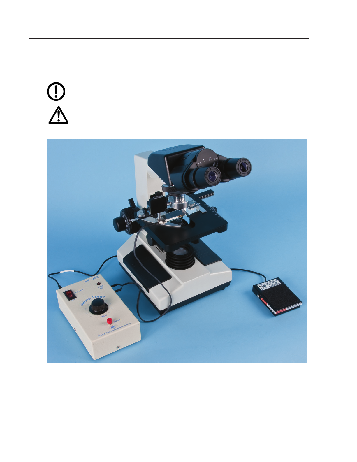
Fig. 1—MF200 System
Page 6
2 World Precision Instruments
INTRODUCTION
The MF200 Microforge is a versatile device designed specically for the fabrication of
glass micropipettes and other related tools. Originally designed by Dr. Ming Li of the
Department of Pharmacology, University of South Alabama, it has been extensively
improved to provide greater accuracy and ease of use. It is simple, durable and
reliable. Ideal for patch pipette polishing, it can also be used for other fabrication
procedures such as pipette tip size reduction, contact stretching to sharpen large
bore pipettes, carbon ber electrode sealing and the production of a variety of pipette
congurations including those for in vitro fertilization. Its simplicity and ease of use
result from two key features:
• Utilization of a microscope to manipulate the pipette
• Unique design of the lament holder that permits attachment of the heating
element directly to the microscope objective.
These features enable precise fabrication specications to be easily met.
CAUTION: The Microforge Control Unit (power) and the heating laments have
been carefully matched to provide rapid lament response at optimum heat
intensity. Use of either of these components with alternate power units or
heating laments may result in severe damage to any or all of these components.
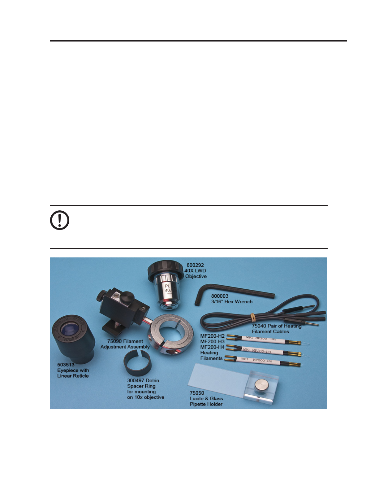
Fig. 2—MF200 Startup Kit
Page 7

MF200
World Precision Instruments 3
INSTRUMENT DESCRIPTION
Parts List
After unpacking, verify that there is no visible damage to the instrument. Verify that all
items are included:
MF200-1/2 Complete Microforge 110V/220V (includes microscope):
(1) W30S Microscope (See W30S Instruction Manual included for set-up, assembly
and operating instructions.)
(1) MF200 Microforge (See parts list below.)
MF200-M1/M2 Microforge 110V/220V (microscope not included):
(1) MF200 Microforge Control Unit
(1) 14470 AC to 12VDC converter with power cord (USA only)
(1) Man-MF200 MF200 Instruction Manual
(1) 75006 MF-200 Start-Up Kit, including:
(1) 800292 40× long-working distance objective
(1) 75050 Lucite and glass pipette holder
(1) 75090 Filament Adjustment Assembly for 40× and 25× LWD objectives
(1) 75040 One pair of heating lament connecting cables
(1) 800003 3/16 hex wrench
(1) MF200-H2 H2 Heating Filament
(1) MF200-H3 H3 Heating Filament
(1) MF200-H4 H4 Heating Filament
(1) 503513 Eyepiece with Linear Reticle
(1) 300497 Spacer Ring for mounting on the 10X objective with 22mm OD
(1) 75027 Spacer Ring for mounting on the 10X objective with 21mm OD
NOTE: The spacer ring (WPI #300497 may not be necessary for objectives with
larger outside diameters. It is use with objectives smaller than 23.0mm.
Unpacking
Upon receipt of this instrument, make a thorough inspection of the contents and
check for possible damage. Missing cartons or obvious damage to cartons should be
noted on the delivery receipt before signing. Concealed damage should be reported
at once to the carrier and an inspection requested. Please read the section entitled
“Claims and Returns” on page 23 of this manual. Please contact WPI Customer
Service if any parts are missing at 941.371.1003 or customerservice@wpiinc.com.
Returns: Do not return any goods to WPI without obtaining prior approval (RMA
# required) and instructions from WPI’s Returns Department. Goods returned
(unauthorized) by collect freight may be refused. If a return shipment is necessary,
use the original container, if possible. If the original container is not available, use a
suitable substitute that is rigid and of adequate size. Wrap the instrument in paper or
plastic surrounded with at least 100mm (four inches) of shock absorbing material. For
further details, please read the section entitled “Claims and Returns” on page 23 of
this manual.
Page 8
4 World Precision Instruments
Description
The complete MF200-1 (110V) and MF200-2 (220V) systems include both the
Microforge and matched microscope (WPI Model W30S); the MF200–M1 (110V) and
MF200-M2 (220V) include the Microforge only.
Optics
The MF200 is the only commercial microforge that includes a 40X long-working
distance objective (LWD). This LWD objective is the most powerful currently available
on any commercially produced microforge. Its 40X magnication is essential when
polishing pipettes as small as half a micron (0.5mm) in diameter. A linear eyepiece
reticle is provided with this system for measureing pipette tip dimensions. An optional
angular reticle is available. See page 19 for details. Optional accessories (including
a 25X LWD objective for the W30S microscope) further expand the MF200 system
functionality.
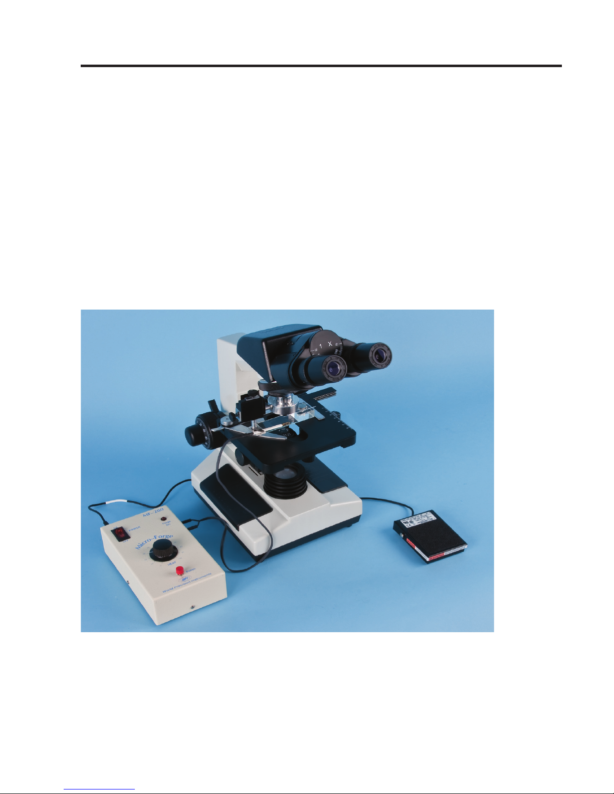
Fig. 3— MF200 System (not shown: 12 V DC power converter for Microforge Control
Unit).
Page 9
MF200
World Precision Instruments 5
Positioning and Focus
Finding and moving the pipette tip under the microscope objective is simple. With a
conventional microforge, it is dicult and time-consuming to position both the heating
lament and pipette in the viewing area using independent micromanipulators.
A unique feature of the MF200 is the heating lament, inserted into the Filament
Adjustment Assembly, which is directly attached to the microscope’s objective
and (using the horizontal and vertical adjustment knobs of the assembly) can be
easily maneuvered to any position within the viewing area. Once the correct focus
is obtained, the lament will remain xed and within focus, and attention can be
turned towards positioning the pipette that rests on the microscope stage. The X-Y-Z
movements of the microscope stage adjustment controls its position relative to the
heating lament. This design makes the positioning and microforging of pipettes
extremely easy. The stage of the MF200 W30S microscope has a high quality rail
that ensures precise, smooth and stable control of the pipette’s movement. The
MF200 system conguration eliminates the need and expense of an additional
micromanipulator to control pipette movement.
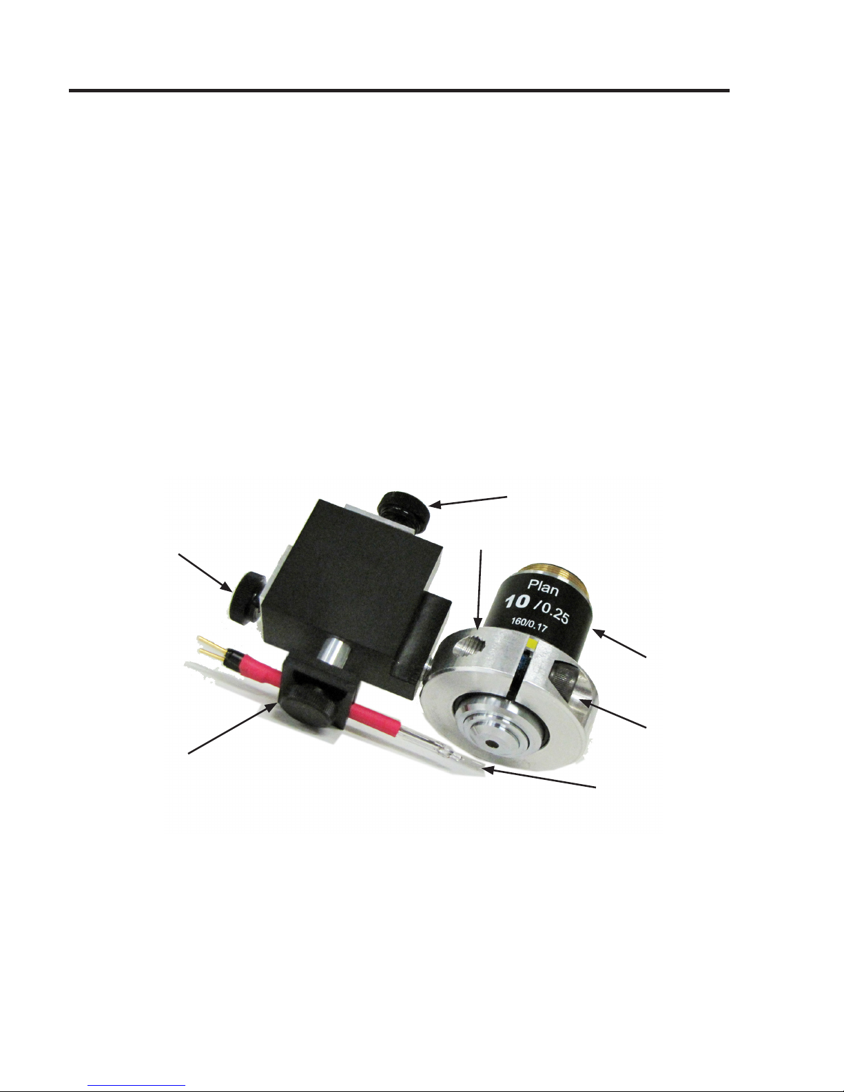
Heating lament
Horizontal
adjustment
Vertical adjustment
Filament
Clamp
10X
objective
Ring
Mounting
screw
Fig. 4—Filament Adjustment Assembly
Heating Filaments
Low heat capacity and low thermal expansion of the laments are key design features
of the MF200 Microforge. The low heat capacity of the lament allows it to reach
re-polishing temperatures without excessive heat. This permits the pipette tip to be
brought close to the lament during polishing without fear of collapsing the pipette tip
and eliminates the need for an auxiliary air cooling system. The low thermal expansion
Page 10

6 World Precision Instruments
characteristic of the lament ensures minimal displacement of the lament during
heating. This feature takes much of the guesswork out of tip placement in relation to
the lament. Three functionally distinct heating laments are provided to meet diverse
application needs.
Table 1: Filaments
Filament Gauge Material Application
H2 0.004” Platinum/iridium wire Large gauge, long: can be formed
into a variety of shapes (reformed)
for fabrication of pipettes up
through the 100-200mm range.
Reforming the lament can result
in a greater heated surface area
to present to the pipette tip. For
large pipettes, it is best used with
the 10X standard objective on the
model W30S microscope (optional
Filament Adjustment Assembly
required) or the optional 25X LWD
objective.
H3 0.002” Platinum/iridium wire Medium gauge, short: for polish-
ing patch clamp pipettes or larger
pipettes up to 3-5mm.
H4 0.001” Platinum/iridium wire Small gauge: for polishing patch
clamp pipettes.
Microscope
The microforge has been matched with WPI research-grade microscope model W30S
to provide an uncomplicated and complete system with excellent performance. The
Filament Adjustment Assembly supplied with the microforge has been designed to
t both the 40X LWD objective (included) and the optional 25X LWD objective for the
W30S microscope. The Filament Adjustment Assembly will t most other microscopes
with a focal length of 160mm. The optional Filament Adjustment Assembly for the 10X
objective is, however, designed specically to t the model W30S 10X objective.
Power Controller (Control Unit)
The MF200 is powered by a 12VDC adapter to supply power to the Control Unit. The
Control Unit is compact and lightweight, and its output power is electrically stable and
reproducible. Fluctuations in the mains voltage input will not aect the output to the
lament. This ensures the same polishing results day to day at the same settings. A
0.5"
.004 wire
Filament MF200-H2
0.18"
.001 wire
Filament MF200-H4
0.25"
.002 wire
Filament MF200-H3
Page 11

MF200
World Precision Instruments 7
push-button polish switch on the Control Unit turns the heating lament on and o.
An optional foot switch is available for complex re polishing. Use of the optional
foot switch leaves the hands free to move the pipette and control the variable heat
adjustment on the Control Unit.
FILAMENT
OUTPUT
70
60
80
50
40
30
20
90
100
POWER
World Precision I
nstruments
LARG E
SMALL
ON
Forge
On
OFF
MF-200
HEAT
Polish
-
+
+12 VDC IN
FOOT
SWITCH
OPTION
FILAMENT
POWER
M
I
C
R
O
F
O
R
G
E
12VDC input
Set power level for
filament to be used:
LOW (or LARGE), HIGH
(or SMALL)
Input for optional
foot switch
Rocker
switch lights
up when
power is on
Connectors
for cables to
filament
Heat dial
control
varies
power to
heating
element
Polish button sends
current to the filament
Fig. 5—Microforge Control Unit
Page 12

8 World Precision Instruments
OPERATING INSTRUCTIONS
Setting up the MF200
Four steps are required to set up the MF200. First, mount the LWD to the microscope.
Then, mount the Filament Adjustment Assembly to the microscope. Next, position the
micropipette holder on the microscope stage. Finally, install the heating lament.
Mounting the LWD to the Microscope
1. Mount the long-working distance (LWD) objective to an available position on the
microscope.
2. Lower the microscope stage as far it will go.
3. When using the 10X LWD, slide the Spacer Ring (WPI #300497) over the tip of the
objective as shown in Figure 6. This Filament Adjustment Assembly slides over the
Spacer Ring for a snug t.
Fig. 6—Slide the Spacing Ring over the objective tip
NOTE: The spacer ring (WPI #300497) may not be necessary for objectives with larger
outside diameters. It is use with objectives smaller than 23.0mm. To determine if you need
a spacer, measure the outside diameter of your objective and refer to the chart below.
Outside Diameter of
Objective Spacer Required
Objectives
Aected
21.0mm WPI #75027 Some 10X
22.0mm WPI #300497 Some 10X
23.0mm none Some 10X
23.5mm none 40X LWD
Page 13

MF200
World Precision Instruments 9
Mounting the Filament Adjustment Assembly to the
Microscope
1. Using the 3/16 hex wrench provided, loosen the mounting screw on the Filament
Adjustment Assembly to open the ring so that it will t comfortably over the
objective and the Spacing Ring (Fig. 7).
2. Swing the objective to an outside position. It should not pointed directly down.
Mount the Filament Adjustment Assembly onto the objective by carefully placing
the ring around the objective and then sliding it up until it stops.
3. While maintaining the Filament Adjustment Assembly in position on the
objective, slowly swing the objective down into the viewing position. Once in
place, position the horizontal adjustment slider to the left of the microscope
objective and parallel to the long edge of the microscope stage (Fig. 7). With the
3/16 hex wrench, tighten the mounting screw on the ring to secure the Filament
Adjustment Assembly to the objective.
Filament Clamp
Horizontal
Adjustment Slider
Spacing Ring
Mounting Screw
3/16" Hex Wrench
Fig. 7—Mounting screw and proper orientation of the lament adjustment assembly
CAUTION: Do not overtighten the mounting screw. Too much force can
damage the objective.
NOTE: The lament clamp and base plate attached to the vertical lament
adjustment is angled slightly inward. This is normal. Do not attempt to straighten
it. This angle facilitates viewing of the lament under the microscope.
Page 14

10 World Precision Instruments
4. Connect the appropriate plug from the AC/DC converter into the 12VDC
receptacle on the Microforge Control Unit, and then plug the converter into a wall
outlet.
Positioning the Micropipette Holder
Position the Pipette Holder on the microscope stage as if it were a slide. Orient the
Lucite block of the pipette holder as shown in Figure 8.
Fig. 8—Micropipette positioned on the microscope stage
Mounting the Heating Filament
1. Position the heating lament in the lament clamp and tighten the knob on the
bottom of the lament holder.
2. Attach both of the microforge connecting cables to the lament by tting the
socket end of each cable into the lament plugs. The cables are interchangeable
and can be used for either plug.
3. Take the free end of each cable and insert each into one of the two Filament
Output receptacles located on the side of the Microforge Control Unit. Again, it
does not matter which cable is connected to each receptacle. The connecting
cable wires from the Microforge Control Unit are not polarized, so reversing these
cables will do no harm.
Page 15

MF200
World Precision Instruments 11
Basic Operations for Using the MF200
This section describes the nal preparations and general instructions for using the
MF200. Specic instructions are detailed for some of the MF200 common uses in
“Applications” on page 14.
NOTE: Remember that (because of microscope optics) any object seen through
the microscope objective is a reverse image of the object and will appear reversed
in orientation. For example, the heating lament (attached to the left side of the
objective) will appear through the microscope as coming from the right.
1. Turn on the power to the microscope.
2. Choose the desired lament. See “Heating Filaments” on page 5.
3. Mount and connect the heating lament. See “Mounting the Heating Filament” on
page 10.
4. Bring the lament into focus:
Without using the microscope, adjust the position of the lament by moving it
in or out and side to side until the lament wire is centered approximately 3mm
below the objective.
Looking through the microscope, move the lament in the lament clamp until
its shadow appears. Some vertical adjustment may also be required to bring the
shadow into the eld.
Using the Vertical Adjustment, bring the lament into clearer view. With the
Horizontal Adjustment, position the end loop of the lament to the far right side
of the visual eld.
5. Power up the MF200 unit. To do this, connect the AC/DC converter to the power
input jack on the Microforge Control Unit and the wall socket. A light in the
POWER switch indicates that the unit is powered up.
• Pressing the Polish push-button switch sends current through the lament
and turns on the Forge On lamp.
• Turning the HEAT dial from 0 to 100 (an arbitrary numbering scale) varies the
amount of power applied to the lament.
• An optional foot switch (WPI #MF200-FS) leaves the hands free to vary the
lament heat intensity while positioning the pipette. Some microforging
techniques will require this two-handed approach.
CAUTION: Since the working distance of the 40X LWD objective is only 3mm,
the objective lens may be damaged by prolonged exposure to the heat
produced by the heating laments. If, for example, the heat is set to 99%, the
larger lament should be used in short bursts. For longer exposure times, lower heat
settings should be used.
Page 16

12 World Precision Instruments
NOTE: The underside of the Microforge Control Unit and the AC/DC converter
become warm to the touch during use. This is normal and no action is required.
6. Position the heating lament and the pipette:
With the Power on, depress the Polish button several times at various heat
settings to see the expansion of the lament loop and determine approximately
where the pipette should be positioned in relation to it.
Position a pipette by rst adjusting the stage of the microscope down and away
from the objective to provide sucient room for mounting the pipette safely on
the pipette holder.
Place the pipette in the Pipette Holder.
Position the pipette using the horizontal adjustment on the microscope stage so
that the pipette tip is slightly past the center of the objective.
Raise the stage until the lament is a few millimeters from the objective. (Fig. 8.)
Slowly move the pipette back and forth, in and out, while looking through the
microscope until the shadow of the pipette is observed.
Adjust the vertical position of the stage until the pipette is clearly visible and in
focus.
Position the pipette tip in relation to the heating lament as required by the
application.
7. Adjust the Filament Power Select switch and Heat dial.
CAUTION: It is not necessary to operate the unit at high power with the Heat
dial set at 100 if the system is used properly. This can cause the laments to
burn out prematurely.
NOTE: Whenever changing laments, turn o the power. When switching power
levels, always set the Heat dial to 0.
The Filament Select slide switch on the side of the Control Unit is marked LARGE
(or LOW) and SMALL (or HIGH). It controls the maximum power to the lament.
The Heat dial provides a range of power up to the maximum as determined by
the Filament Select switch. Always begin with the dial at the low end of the range
and increase the heat only as necessary and by small increments. The lowest
power and heat setting that can be used to accomplish a task should be used.
Higher heat than necessary may shorten lament life, as well as increase the
possibility of overheating the pipette tip.
Page 17

MF200
World Precision Instruments 13
Table 2: Filament Power Switch
Filament LARGE (or LOW) Power Position SMALL (or HIGH) Power Posi-
tion
H2 When polishing large pipette tips,
the H2 lament works best. In
most cases LOW power will perform satisfactorily. Tips of 100mm
and larger may require switching the power to HIGH. See “Fire
Polishing Large Bore Pipettes” on
page 16.
Will rapidly decrease lament
life as the Heat dial approach-
es 100. Restrict time at high
heat to a minimum.
H3
and
H4
Best for polishing patch pipettes. HIGH power may be required
for pipettes above 0.5mm.
Page 18

14 World Precision Instruments
Applications
Choice of laments, power and heat settings for each application vary with the use. If
the desired result is achieved, the choice of parameters is acceptable. Always use the
least amount of heat possible in order to prolong the life of the laments.
The distance that should be maintained between the lament and the pipette tip
during microforging varies depending on the tip bore, lament, power, heat settings
and application. With the exception of the applications in which a glass bead is formed
on the lament, the tip should not come in contact with the lament. In general, it is
best to begin with the tip at a safe distance from the lament and move toward it, as
necessary.
The formation of a glass bead on the lament is required for certain applications. See
“Microforging Beveled Injection Pipettes” on page 17. It is not required for the other
applications described in this manual, however, a glass bead on the lament may be
used for other applications, if desired.
Fire Polishing the Patch Clamp Pipette
Fire polishing is a two step process, involving coating the pipette and polishing it.
Step 1: Coat the Single-Channel Patch Clamp Pipette.
Coat the single-channel patch clamp pipette with Sylgard 184 before polishing. (A
simple and eective coating method has been described by Dr. Li.
WARNING: Always wear safety glasses during this procedure. Never
point the pipette at anyone. The pipette can be forcefully shot out of
its holder if not tightly secured.
1. Briey, t the pipette into a pipette holder, which is connected to a low-pressure,
clean air source. Force air through the pipette at a pressure greater than 20PSI
(for an 0.5 ID pipette) in order to prevent the Sylgard from entering the pipette tip
during the coating process.
2. After mixing the Sylgard, dip the pipette tip into the coating and remove it.
3. With the low-pressure air supply still applied, place the pipette tip over a heat gun
for two seconds in order to cure the Sylgard.
4. Remove the air supply from the pipette. The pipette is now coated and the tip
is ready to be polished following the procedure for the whole cell patch clamp
pipette as described in Step 2.
Page 19

MF200
World Precision Instruments 15
Step 2: Fire Polish the Single-Channel and Whole Cell Patch
Clamp Pipette
1. Choose and install the desired lament. (See “Table 2: Filament Power Switch” on
page 13.)
2. Turn on the Control Unit power.
3. Hold down the Polish button and adjust the Heat Dial from low to high while
observing the expansion of the lament under the microscope. A slight
movement of the lament indicates that it has sucient heat and will provide
excellent polishing results in most cases.
NOTE: A red-hot lament is unnecessary and undesirable and will decrease the
life of the lament. It also heats the tip too quickly, making it dicult to control
the degree of polishing. In addition, a red-hot large lament could permanently
damage the 40X objective.
4. Place the pipette to be polished in the pipette holder.
5. Adjust the microscope stage until the pipette is in position with sucient distance
to account for lament expansion (Fig.9).
Heat off
Heat on
Fig. 9—(Left)Untreated tip
Fig. 10—(Right) Fire polished tip
6. Press Polish and observe the expansion movement of the lament (Fig.10).
7. Determine the appropriate Heat dial setting and then ne-tune the position of the
tip. A minimal change in the shape of the tip typically yields good polishing results.
Fire Polishing a Pipette Tip
To re polish a pipette tip, follow the instructions under “Step 2: Fire Polish the Single-
Channel and Whole Cell Patch Clamp Pipette” on page 15.
Page 20

16 World Precision Instruments
Tip Size Reduction
Tip size reduction creates a holding pipette by rounding the tip ends and reducing the
length of the pipette tip (Fig. 11).
Fig. 11—(Right) Tip size reduction
1. Choose and install the desired lament.
(See “Table 2: Filament Power Switch” on
page 13.)
2. Turn on the Control Unit power.
3. Select the appropriate Filament power.
4. Press the Polish button and set the Heat
dial to a setting at which the lament just starts to glow red. Release the Polish
button.
5. Place the pipette to be reduced in the pipette holder. Adjust the microscope
stage until the pipette is in position with sucient distance to account for lament
expansion.
6. Turn on the heat by pressing the Polish button and observe the melting of the tip.
Maintain the heat until the desired opening size is obtained.
TIP: If the process is too slow, move the tip closer to the lament. (It is better to
do this operation very slowly in stages, in order to avoid making the tip too small.)
Fire Polishing Large Bore Pipettes
To re polish large bore tips (100–200mm), the H2 lament can be shaped or re-
formed to be slightly larger than the pipette
tip. (See Fig. 12 and 13.)
Fig. 12—(Right) Reshaped lament
This eectively provides an increase in
the heated surface area presented to
the tip with a resulting increase in the
heat directed to the large bore tip. This is
necessary to melt the thicker glass of a large
bore pipette. Larger bore tips generally
require the use of the 10X objective.
Fig. 13—Reshaped lament with large bore tip
Under some circumstance, it may be possible to use the 25X LWD objective. After re-
forming the lament, proceed to microforge as described in “Fire Polishing a Pipette
Heat off
Page 21

MF200
World Precision Instruments 17
Tip” on page 15.
Tip Reduction of Large Bore Pipettes
The re-formed H2 lament described in “Fire Polishing Large Bore Pipettes” can also
be used for tip size reduction of large bore pipettes. To reshape the tip end and
reduce its size, re-form the lament so that the tip will t inside the lament outline
(Fig. 14) and proceed to microforge, described in “Tip Size Reduction” on page 16.
Fig. 14—Reshaped lament reduces large bore tip
Reducing Overall Filament Expansion
Re-forming or shaping the H2 lament as shown in Figure 15 can also be used as a
means to reduce overall lament expansion.
Fig. 15—Alternate lament shape
Microforging Beveled Injection Pipettes
Frequently, a beveled large bore pipette is not sharp enough to penetrate a cell
without causing damage to the surrounding area. With the MF200 and the H2 heating
lament, a sharp point can be formed on a beveled tip to assist in the penetration of
the cell with minimal damage, using a two step process. First form a glass bead on the
lament, and then sharpen the beveled edge of the pipette.
Step 1: Form Glass Bead on the Filament
For this application, rst form a glass bead around the lament by coating the
midpoint of the lament with a small amount of glass.
1. Position a small scrap pipette in the pipette holder.
Page 22

18 World Precision Instruments
2. Adjust the microscope stage until the pipette is in position to allow the tip to
touch the lament during expansion.
3. Set the dial so the lament starts to glow red. Press Polish and coat the center
of the lament with glass until a bead about twice the diameter of the lament is
formed.
4. Release the Polish button. Remove the scrap pipette from the holder.
Step 2: Sharpen the Beveled Edge of the Pipette
1. Place the beveled pipette in the pipette holder. With the pipette tip far from the
heat, press Polish and adjust the heat until the glass bead is molten (Fig. 16).
Fig. 16—(Left) Glass bead formed on lament
Fig. 17—(Right) Pipette tip close to glass bead
2. With heat o, move the tip very close to the glass bead (Fig. 17).
3. Press the Polish button. The lament expands, touching the tip of the beveled
glass. As glass the bead becomes molten and the beveled tip makes contact with
the bead, quickly pull the tip away and simultaneously release the Polish button
to turn o the heat. (Fig. 18).
Fig. 18— (Left) Filament expands and contacts the tip
Fig. 19—(Right) Pipette has a sharp tip
4. The resulting tip (Fig. 19) has a very sharp point for clean cell penetration.
Page 23

MF200
World Precision Instruments 19
INSTRUMENT MAINTENANCE
The requirements for the maintenance and storage of the MF200 are minimal. Care
should be taken to protect the laments. Store them in their original container when
not in use. In general, it is advisable to keep the MF200 in an area with minimal dust
and particulates as would be appropriate for any microscope or similar apparatus.
ACCESSORIES
Table 3: Accessories
Part Number Description
–––––– Optional Angular Reticle*
300497 Delrin Spacing Ring for 10X objective
(0.86”)
75027 Delrin Spacing Ring for 21mm 10X ob-
jective
500292 15× Eyepieces (pair)
13142 MF200 optional foot switch
500329 25× Long-Working Distance objective
(5mm): ts most microscopes with a 160
mm Focal Length
*Optional angular reticle (19mm) is available. Contact Technical support for details at
941.371.1003 or technicalsupport@wpiinc.com.
Fig. 20—Optional angular eyepiece reticle
Page 24

20 World Precision Instruments
SPECIFICATIONS
AC POWER MODULE 100-240 VAC 50/60Hz
FILAMENTS (3) H2, H3, H4
FILAMENT “ON” CONTROL Push button or Optional Foot Switch
FILAMENT ADJUSTMENT ASSEMBLY Mounts on 40× and 25× Long-Working
Distance Objectives
OBJECTIVE 40× Long-Working Distance (3 mm)
EYEPIECE 10× (pair)
RETICLE (10× eyepiece for W30S only) 1.25µm/division (at 40×):
0-90° angle at 5°/division (optional)
GLASS HOLDER Mounts on microscope stage
DIMENSIONS (Control Unit) 10.2 × 17.8 × 4.8cm (4 × 7 × 17/8in.)
SHIPPING WEIGHT 1.4kg (3lb.)
MICROSCOPE See Model W30S Instruction Manual
SHIPPING WEIGHT 7.3kg (16lb.)
For W30S microscope specications, refer to the W30S Instruction Manual.
APPENDIX A: MICROSCOPE OBJECTIVE
INFORMATION
Table 4: DIN Plan Achromat (160mm) Information
Magni-
cation
Numeri-
cal Apera-
ture
Approx.
Field of
View
Approx.
Working
Distance
Body
Diameter
Approx.
Depth of
Focus
4X 0.10 4.5mm 17mm 20mm ~90mm
10X 0.25 1.8mm 2mm 20-23mm ~15mm
25X LWD 0.50 0.72mm 5mm 23.4mm ~5mm
40X 0.65 0.45mm 0.65mm NA ~20mm
40X LWD 0.65 0.45mm 3mm 23.4mm ~20mm
100X (oil) 1.25 0.18mm contact NA <1mm
Page 25

MF200
World Precision Instruments 21
INDEX
A
accessories 19
air supply 14
applications 14
B
base plate 9
burn out 12
C
changing laments 12
control unit 6
F
Filament Adjustment Assembly 3, 5, 6
mounting 8, 9
lament clamp 9, 10, 11
lament expansion reduction 17
Filament Output receptacles 10
Filament Power Switch 13
Filament Select switch 12
re polishing
large bore pipettes 16
patch clamp 14
pipette tip 15
focal length 6
foot switch 11
G
glass bead 14, 17, 18
H
H2 6, 13, 17
H3 6, 13
H4 6, 13
heat capacity 5
Heat dial 11
heat lament 5
changing 12
Horizontal Adjustment 11
L
large bore pipettes 17
LWD 6
M
maintenance 19
micropipette holder
positioning 10
P
patch clamp pipette 14
pipette holder 10
platinum/iridium 6
Polish push button 11
position microforge 5
power controller 6
R
reduce overall lament expansion 17
reticle, angular 19
reverse image 11
S
sharpen beveled edge 18
sharp point 18
specications 20
storage 19
Sylgard 14
T
tip size reduction 16
V
Vertical Adjustment 11
W
W30S 3, 4, 5, 6, 20
Page 26

22 World Precision Instruments
DECLARATION OF CONFORMITY
Page 27

MF200
World Precision Instruments 23
* Electrodes, batteries and other consumable parts are warranted for 30 days only from the date on which
the customer receives these items.
WARRANTY
WPI (World Precision Instruments, Inc.) warrants to the original purchaser that this equipment, including
its components and parts, shall be free from defects in material and workmanship for a period of
one year* from the date of receipt. WPI’s obligation under this warranty shall be limited to repair or
replacement, at WPI’s option, of the equipment or defective components or parts upon receipt thereof
f.o.b. WPI, Sarasota, Florida U.S.A. Return of a repaired instrument shall be f.o.b. Sarasota.
The above warranty is contingent upon normal usage and does not cover products which have been
modied without WPI’s approval or which have been subjected to unusual physical or electrical stress
or on which the original identication marks have been removed or altered. The above warranty will not
apply if adjustment, repair or parts replacement is required because of accident, neglect, misuse, failure
of electric power, air conditioning, humidity control, or causes other than normal and ordinary usage.
To the extent that any of its equipment is furnished by a manufacturer other than WPI, the foregoing
warranty shall be applicable only to the extent of the warranty furnished by such other manufacturer.
This warranty will not apply to appearance terms, such as knobs, handles, dials or the like.
WPI makes no warranty of any kind, express or implied or statutory, including without limitation any
warranties of merchantability and/or tness for a particular purpose. WPI shall not be liable for any
damages, whether direct, indirect, special or consequential arising from a failure of this product to
operate in the manner desired by the user. WPI shall not be liable for any damage to data or property
that may be caused directly or indirectly by use of this product.
Claims and Returns
Inspect all shipments upon receipt. Missing cartons or obvious damage to cartons should be noted on
the delivery receipt before signing. Concealed loss or damage should be reported at once to the carrier
and an inspection requested. All claims for shortage or damage must be made within ten (10) days
after receipt of shipment. Claims for lost shipments must be made within thirty (30) days of receipt of
invoice or other notication of shipment. Please save damaged or pilfered cartons until claim is settled.
In some instances, photographic documentation may be required. Some items are time-sensitive; WPI
assumes no extended warranty or any liability for use beyond the date specied on the container
Do not return any goods to us without obtaining prior approval and instructions from our Returns
Department. Goods returned (unauthorized) by collect freight may be refused. Goods accepted for
restocking will be exchanged or credited to your WPI account. Goods returned which were ordered
by customers in error are subject to a 25% restocking charge. Equipment which was built as a special
order cannot be returned.
Repairs
Contact our Customer Service Department for assistance in the repair of apparatus. Do not return
goods until instructions have been received. Returned items must be securely packed to prevent
further damage in transit. The Customer is responsible for paying shipping expenses, including
adequate insurance on all items returned for repairs. Identication of the item(s) by model number,
name, as well as complete description of the diculties experienced should be written on the repair
purchase order and on a tag attached to the item.
Page 28

USA
International Trade Center, 175 Sarasota Center Blvd., Sarasota FL 34240-9258
Tel: 941-371-1003 • Fax: 941-377-5428 • E-mail: sales@wpiinc.com
UK
1 Hunting Gate, Hitchin, Hertfordshire SG4 0TJ
Tel: 44 (0)1462 424700 • Fax: 44 (0)1462 424701 • E-mail: wpiuk@wpi-europe.com
Germany
Zossener Str. 55, 10961 Berlin
Tel: 030-6188845 • Fax: 030-6188670 • E-mail: wpide@wpi-europe.com
China & Hong Kong
WPI Shanghai Trading Co., Ltd.
Rm 29a, No8 Dongfang Rd., Pudong District, Shanghai, 200120 PR China
Tel: +86 21 6888 5517 • E-mail:chinasales@china.wpiinc.com
Brazil
Av. Conselheiro Nébias, 756 sala 2611, Santos-CEP: 11045-002, São Paulo Brazil •
Tel: (013) 406-29703 • E-mail: info@brazil.wpiinc.com
Internet
www.wpiinc.com • www.wpi-europe.com • www.wpiinc.cn
 Loading...