

Page 1

INSTALL GUIDE
Serial No._____________________
INV-101
Inverted Microscope
102811
www.wpiinc.com
World Precision Instruments
Page 2

INV-101
II
WORLD PRECISION INSTRUMENTS
Page 3

INV-101
CONTENTS
ABOUT THIS MANUAL ............................................................................................................................... 1
INTRODUCTION ............................................................................................................................................ 2
Unpacking ................................................................................................................................................. 2
MICROSCOPE SETUP ................................................................................................................................... 3
Setting up the Base and Stage ........................................................................................................... 3
Installing the Condenser and Lamp Housing ................................................................................ 7
Setting up the Stage and Phase Aperture ....................................................................................... 9
Installing the Trinocular Head Assembly ........................................................................................ 9
Installing the Objectives .....................................................................................................................11
Installing Adapter Plates, Eyepieces and Filters ..........................................................................13
Phase Contrast Alignment .................................................................................................................17
Adjusting the Phase Contrast Alignment ................................................................................17
Mounting a Camera .............................................................................................................................19
Direct C-Mount on a Threaded Triangular Attachment ..................................................... 20
Vertical Eye Tube Mounting .........................................................................................................21
Eyepiece Mounting .........................................................................................................................21
Eyepiece Plus C-Mount Mounting ...................................................................................................22
BASIC MICROSCOPE OPERATIONS ......................................................................................................23
Camera Shutter (Optical) Path...........................................................................................................23
Coaxial X-Y Control ..............................................................................................................................23
Micrometer Focus Control .................................................................................................................. 24
Focus Tensioning Adjustments .........................................................................................................24
INDEX .............................................................................................................................................................27
WARRANTY ..................................................................................................................................................28
Claims and Returns ..............................................................................................................................28
Copyright © 2011 by World Precision Instruments, Inc. All rights reserved. No part of this publication may be
reproduced or translated into any language, in any form, without prior written permission of World Precision
Instruments, Inc.
WORLD PRECISION INSTRUMENTS
iii
Page 4

INV-101
IV
WORLD PRECISION INSTRUMENTS
Page 5
ABOUT THIS MANUAL
The following symbols are used in this guide:
This symbol indicates a CAUTION. Cautions warn against actions that can cause
damage to equipment. Please read these carefully.
This symbol indicates a WARNING. Warnings alert you to actions that can cause
personal injury or pose a physical threat. Please read these carefully.
NOTES and TIPS contain helpful information.
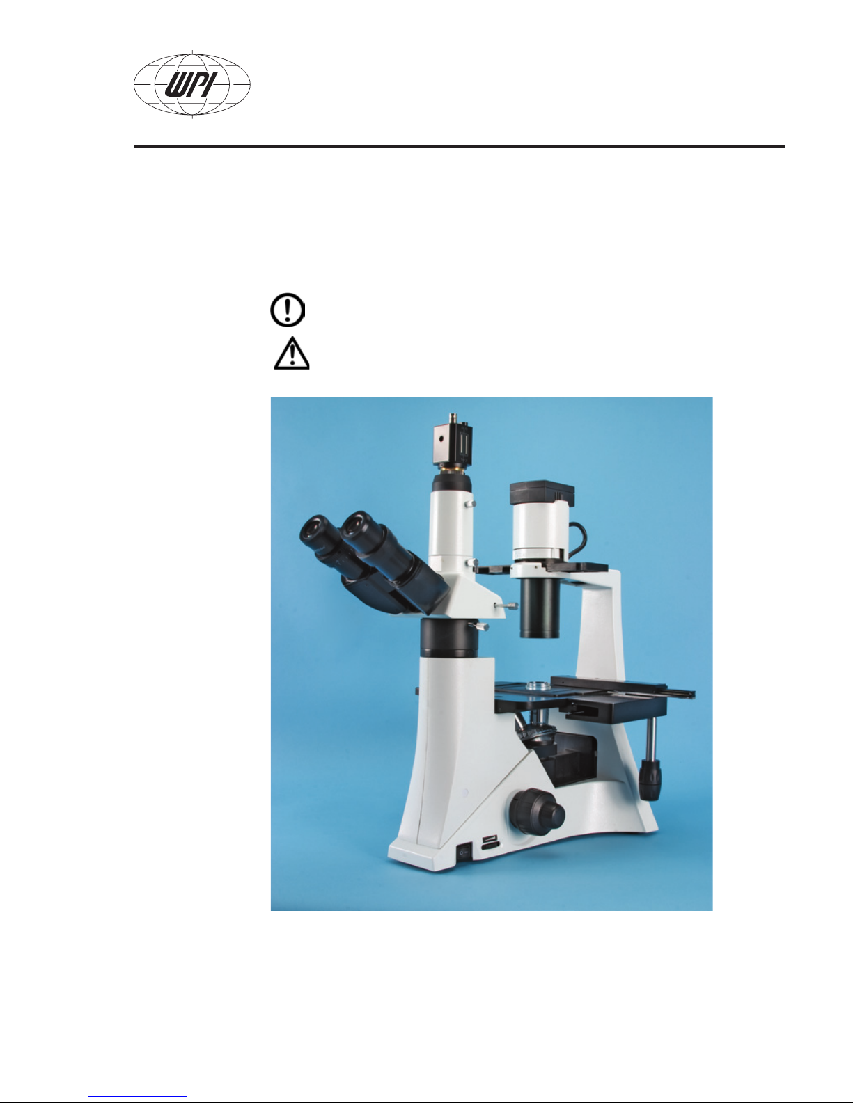
INV-101
Fig. 1–INV-101 Inverted microscope
WORLD PRECISION INSTRUMENTS
1
Page 6
INV-101
INTRODUCTION
This document details the assembly of the INV-101 inverted microscope. It includes
optional installation of a camera. All cameras and mounting adapters are sold separately.
Unpacking
Upon receipt of this instrument, make a thorough inspection of the contents and check
for possible damage. Missing cartons or obvious damage to cartons should be noted on
the delivery receipt before signing. Concealed damage should be reported at once to the
carrier and an inspection requested. Please read the section entitled “Claims and Returns”
on page 28 of this manual. Please contact WPI Customer Service if any parts are
missing at 941.371.1003 or customerservice@wpiinc.com.
Returns: Do not return any goods to WPI without obtaining prior approval (RMA #
required) and instructions from WPI’s Returns Department. Goods returned (unauthorized)
by collect freight may be refused. If a return shipment is necessary, use the original
container, if possible. If the original container is not available, use a suitable substitute
that is rigid and of adequate size. Wrap the instrument in paper or plastic surrounded with
at least 100mm (four inches) of shock absorbing material. For further details, please read
the section entitled “Claims and Returns” on page 28 of this manual.
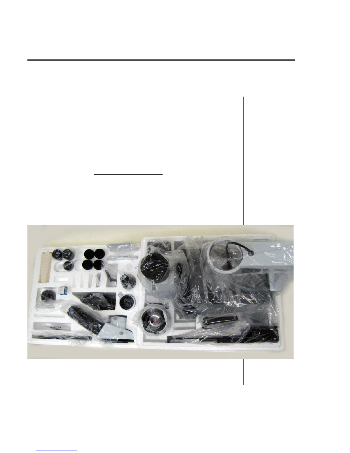
Fig. 2–Contents of the two boxes
2
WORLD PRECISION INSTRUMENTS
Page 7

INV-101
MICROSCOPE SETUP
Before setting up the microscope, carefully open the box and inspect its contents. The
pieces of the microscope are stored in two Styrofoam containers, and many of the
pieces are wrapped in plastic (Fig. 2). Carefully unwrap each piece before setting up the
instrument. The following instructions graphically show how to setup your inverted
microscope.
NOTE: If you have a problem/issue that falls outside the definitions of this manual,
contact the WPI Technical Support team at 941.371.1003 or technicalsupport@wpiinc.
com.
Setting up the Base and Stage
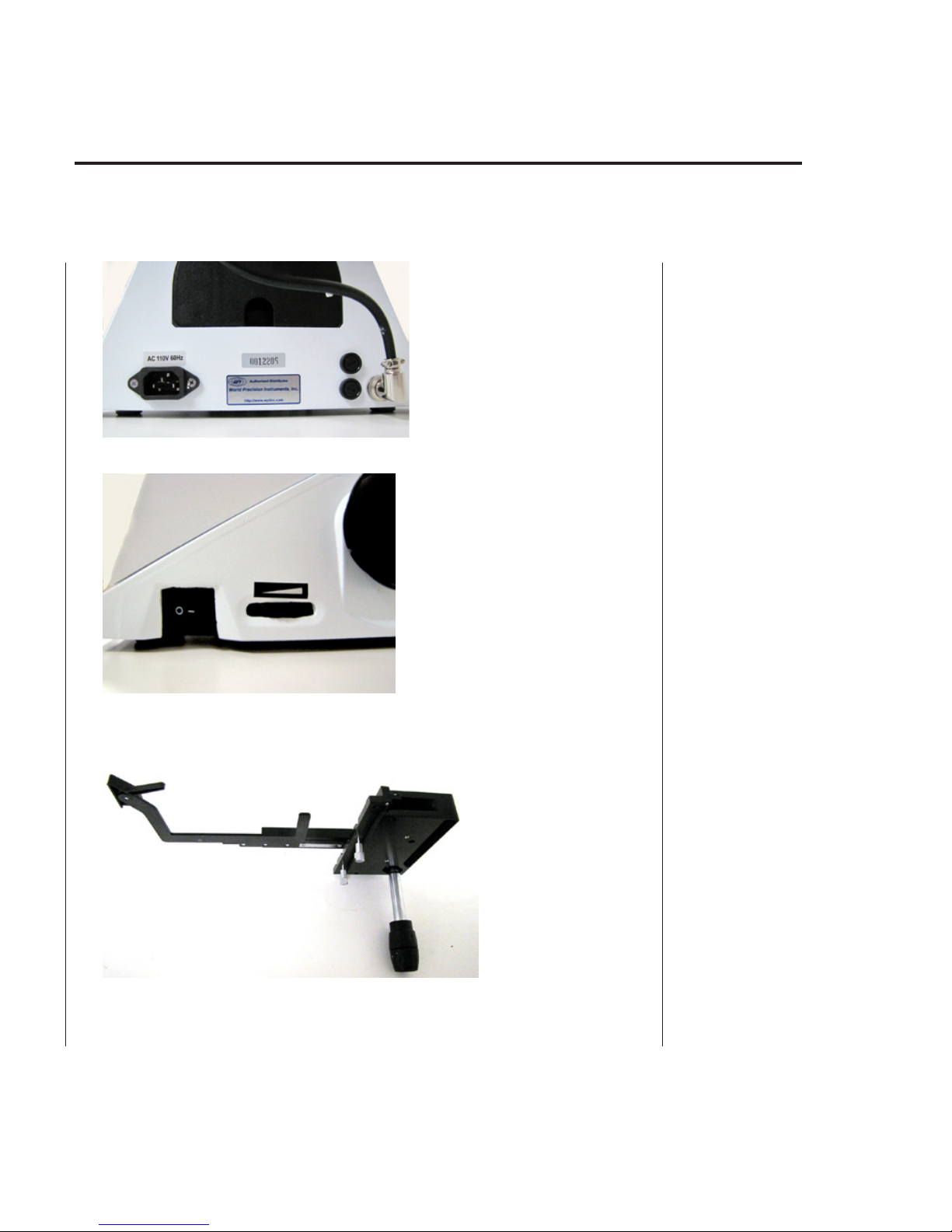
1. Remove the base of the microscope and set it up on a firm tabletop surface (Fig. 3).
Fig. 4 shows the back of the microscope base. The A/C power plug adapter, the serial
number and the fuse compartment are located on the back. Fig. 5 shows the power
switch and lamp brightness control located on the side of the microscope.
Fig. 3–Base of the microscope.
Condenser Mount
Lamp Connector
Stage
Head Mount
5-Position Nosepiece
Focus Control Knob
FrontBack
WORLD PRECISION INSTRUMENTS
3
Page 8
INV-101
Fig. 4–Back of the microscope base showing power connection, serial number and fuse
compartment
Fig. 5–Power switch and lamp brightness control on the side of the microscope
2. Locate the coaxial stage assembly. It is shown in Fig. 6. The captive mounting screws
are located on the side of it (Fig. 7).
Fig. 6–Coaxial stage assembly
4
WORLD PRECISION INSTRUMENTS
Page 9
INV-101
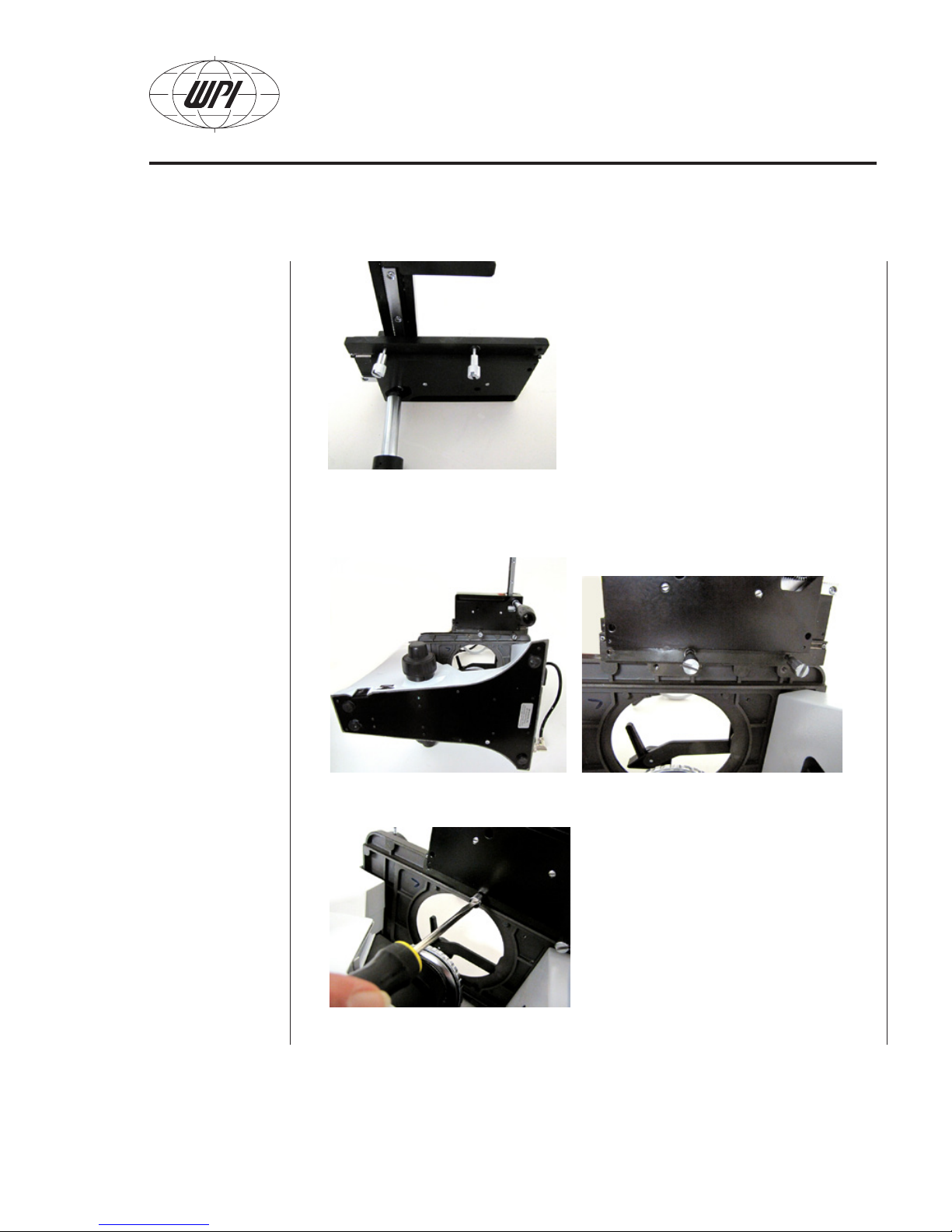
Fig. 7–Captive mounting screws on the coaxial stage assembly
3. Tip the microscope base over on its left side to reveal the location of the screw
mounts. Then, position the coaxial stage (Fig.8). Fig. 9 shows a close up of the captive
screws.
Fig. 8–Microscope on its side Fig. 9–Close up of captive mounting screws
4. With a flat head screwdriver, gently tighten the captive screws (Fig. 10).
Fig. 10–Gently tighten the captive mounting screws.
WORLD PRECISION INSTRUMENTS
5
Page 10
INV-101
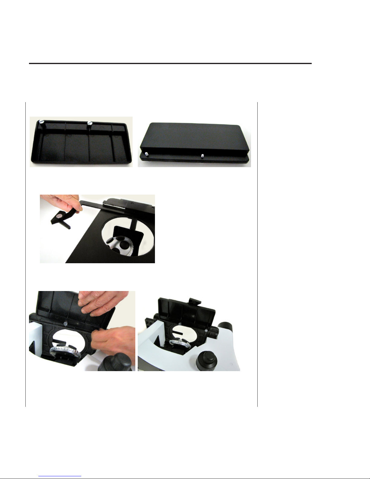
5. Locate the left extension stage plate bottom shown in Fig. 11 (bottom view) and Fig.
12 (top view).
Fig. 11- Extension stage plate (bottom view) Fig. 12–Extension stage plate (top view)
6. Push extension arm of the coaxial stage assembly inward so that you do not damage
it when you mount the left extension stage plate (Fig. 13).
Fig. 13–Extension arm of coaxial stage assembly.
7. Then, with the microscope base laying on its right side, locate the captive screws and
mounting holes for left stage plate (Fig. 14) and install the left stage plate (Fig. 15).
Fig. 14–Left stage plate captive screws Fig. 15–Plate installed viewed from below
6
WORLD PRECISION INSTRUMENTS
Page 11

8. Turn the microscope upright (Fig. 16).
Fig. 16–Coaxial and left stage plate mounted
Installing the Condenser and Lamp Housing
1. Locate the condenser assembly and lamp housing (Fig. 17).
Condenser
Assembly
INV-101
Lamp Housing
Fig. 17–Condenser assembly and lamp housing
2. Lower the condenser assembly into the condenser mount (Fig. 18). It should slide
easily into place. (Note the orientation.) Then, rotate the condenser assembly 90º
counter-clockwise into position (Fig. 19).
Fig. 18–Condenser in mounting position Fig. 19–Condenser rotated 90º CCW
WORLD PRECISION INSTRUMENTS
7
Page 12

INV-101
3. Tighten hex screws to secure the condenser assembly into the condenser mount (Fig. 20).
Fig. 20–Tighten hex screws on condenser head
4. Plug the lamp housing into the lamp connector (Fig. 21).
Fig. 21–Connect the lamp Fig. 22–Lamp connected Fig. 23–Install lamp
5. Lower the lamp housing onto the mounting pin sockets in the top of the condenser
head. (Fig. 23). The assembled condenser and lamp housing is shown in Fig. 24.
Fig. 24–Assembled condenser with lamp housing
8
WORLD PRECISION INSTRUMENTS
Page 13

INV-101
Setting up the Stage and Phase Aperture
1. Position the clear stage plate in the recess on the stage (Fig. 25).
Fig. 25–Clear stage plate, installed
2. Install the phase aperture frame (Fig. 26) in the slot on the condenser head from the
right side. Orient the phase aperture frame as shown in Fig. 27.
10X/20X/40X
Condenser
Annulus
Filter
Frame
Fig. 26–Phase aperture frame Fig. 27–Install the phase aperture frame
Installing the Trinocular Head Assembly
1. Remove the dust cover from the trinocular head assembly (Fig. 28) and the head
mount (Fig. 29).
Fig. 28–Trinocular head and dust cover Fig. 29–Cover on head mount of microscope base
WORLD PRECISION INSTRUMENTS
9
Page 14

INV-101
Trinocular
2. Place the trinocular head on the head mount and tighten the side screw (Fig. 30).
Fig. 30–Position head on the mount
3. Locate the threaded C-mount, eye tube mount and trinocular extension tube (Fig. 31).
Eye Tube
Mount
1X Threaded
C-Mount
Extension Tube
Fig. 31–C-mount, eye tube mount and trinocular tube extension
4. Remove the trinocular extension tube mount dust cover from the trinocular head (Fig.
32) and place the extension tube into the opening (Fig. 33). Tighten the locking screw
on the side.
Fig. 32–Remove dust cover Fig. 33–Position extension tube
10
WORLD PRECISION INSTRUMENTS
Page 15

INV-101
5. Depending on your application, either the eye tube mount or the C-mount can be
installed. Choose one of the two options.
• Mount the eye tube mount by inserting it into the extension tube (Fig. 34).
• Mount the threaded C-mount by screwing it into the extension tube (Fig. 35).
2X C-Mount Here
Fig. 34–Eyepiece tube screw mounted Fig. 35–Threaded C-mount mounted
Installing the Objectives
Four objectives are included with the microscope. They are in protective shipping
tubes with captive dust covers (Fig. 36). The nosepiece allows you to mount up to five
objectives. The nosepiece (for mounting the objectives) is shown in Fig. 37. (The clear
plate was removed for this part of the installation.) When mounting the objectives,
remove the nosepiece dust covers individually when you are ready to install an objective.
Leave the dust covers in place on unused mounting holes.
Fig. 36–Objective, pictured as shipped Fig. 37–5-Position nosepiece
WORLD PRECISION INSTRUMENTS
11
Page 16

INV-101
1. Remove a single dust cover from the nosepiece (Fig. 38). When it is removed, an
opening is revealed (Fig. 39). For ease of installation, that opening should point
straight up through the opening on the microscope stage.
Fig. 38–Removing dust cover to mount objective Fig. 39–Position for mounting objective
2. Remove the desired objective from its shipping case (Fig. 40). Then, remove the captive dust cover (its cap) (Fig. 41).
Fig. 40–Objective out of case Fig. 41–Objective with cap removed
3. Insert the objective into the nosepiece and rotate it clockwise. Finger tighten it
(Fig.42). DO NOT OVERTIGHTEN. Finger tight is sufficient!
Fig. 42–Installing the objective
12
WORLD PRECISION INSTRUMENTS
Page 17

INV-101
4. Rotate the nosepiece to access next mounting location (Fig. 43).
Fig. 43–Rotated nosepiece Fig. 44–Four objectives mounted
5. Repeat steps 1-4 to install the remaining objectives. Do not remove the dust covers
until you are ready to install the next objective. This prevents any stray dust from being trapped on the objective. The final assembly is shown in Fig. 44. The objectives
are arranged in order (4X, 10X, 20X, 40X). An optional fifth objective location is also
provided. If a fifth objective is not installed, leave the dust cover in place.
6. Re-position the clear stage plate in the recess on the stage (Fig. 45).
Fig. 45–Clear stage plate in place
Installing Adapter Plates, Eyepieces and Filters
1. Locate the 100mm round stage mount, rectangular plate and 35mm insert (Fig. 46).
Fig. 46–100mm round stage mount, rectangular plate and 35mm insert
WORLD PRECISION INSTRUMENTS
50mm/1x3” Slide
Adapter
Rectangular
Lab Jar Adapter
35mm Dish
Adapter
13
Page 18

INV-101
2. Insert the 35mm adapter plate into the rectangular plate (Fig. 47).
Fig. 47–Assembled rectangular plate and 35mm insert
3. Place the rectangular plate on the stage plate (Fig 48).
Fig. 48–Placement location of the assembled stage plate
4. Remove the eyepieces from the dust wraps (Fig. 49) and remove the dust covers from
the eyepiece openings on the trinocular head (Fig. 50).
Fig. 49–Eyepieces Fig. 50–Remove dust covers from trinocular
head
14
WORLD PRECISION INSTRUMENTS
Page 19

INV-101
5. Place the eyepieces in the microscope ocular openings (Fig 51). Adjust the diopter set-
ting to zero.
Fig. 51–Placement of eyepieces
6. Locate the filters (Fig. 52).
Fig. 52–Filters
7. Remove the filter holder from the condenser head as shown in Fig. 53 and Fig. 54.
Fig. 53–Filter holder position Fig. 54–Filter holder removed
WORLD PRECISION INSTRUMENTS
15
Page 20

INV-101
8. Place the desired filter in the filter holder (Fig. 55) and slide the holder back into the
condenser head (Fig. 56 and 57).
Fig. 55–Insert filter Fig. 56–Position holder Fig. 57–Slide holder in place
TIP: If desired, the filter may alternatively be placed in the condenser annulus slider (Fig.
58) and slid into position for use (Fig. 59).
Fig. 58–Filter in condenser annulus slider Fig. 59–Condenser annulus slider in position
16
WORLD PRECISION INSTRUMENTS
Page 21

INV-101
Phase Contrast Alignment
There are two phase contrast objectives included with the INV-101 microscope, the 10X
and the 20X. On a simplified level, phase contrast imaging occurs by the interference of
light that is created by special masks in the light path. There are two masks, each located
in a different part of the light path, which must be positioned correctly relative to each
another to create the phase contrast effect.
The annular ring (condenser annulus) is located in
the phase aperture frame, and it has a light masking
pattern that looks similar to Fig. 60. The phase ring
is the conjugate of the condenser annulus, and its
pattern is a ring that is the same size as the white
area in the condenser annulus pattern. The phase
ring pattern is located in the objective and cannot
be adjusted by the user.
The condenser annulus is adjustable by the user, and it is located in the phase aperture
frame. The user adjusts the position of the condenser annulus to establish the proper
relationship between the two masks to optimize the phase contrast effect.
Notice that there are two condenser annulus masks on the phase aperture frame. (See
Fig. 26, page 9.) One is for use with the 10X and 20X phase contrast objectives,
and the larger one is for a 40X phase contrast objective (not included). Adjust the phase
aperture frame so that the correct mask is in the light path corresponding with the objective
to be used.
Condenser Annulus Phase Ring
Fig. 60–Two Annuli
Adjusting the Phase Contrast Alignment
1. Adjust the phase aperture frame so that the open filter hole is in the light path of the
condenser head. With the open filter hole in this position, the only mask in the light
path is the phase ring in the phase contrast objective.
2. Select a phase contrast objective. In this case, it will be either the 10X or the 20X.
3. Replace one of the eyepieces with the phase telescope (Fig. 61).
Fig. 61–Phase telescope in eyepiece
WORLD PRECISION INSTRUMENTS
17
Page 22

INV-101
4. View the phase ring through the phase telescope.
5. Adjust the focus on the phase telescope for a sharp image of the phase ring. The
phase telescope focus is adjusted by screwing it in or out (Fig. 62).
Fig. 62–Focus adjustment
6. Slide the phase aperture fame into position with the 10X/20X condenser annulus in
the condenser light path. (Fig. 63)
NOTE: If you are using a 40X phase contrast objective (not included), use the 40X
condenser annulus on the phase aperture frame.
Fig. 63–Plate position by phase
7. You will see an overlap of the condenser annulus and phase ring patterns through
the phase telescope (Fig. 64). To optimize the phase contrast image, the condenser
annulus must be concentrically aligned with the phase ring. The two rings can be
seen through the telescope. See Fig. 60, page 17.
Fig. 64–Aperature disc seen through the telescope
18
WORLD PRECISION INSTRUMENTS
Page 23

INV-101
8. To adjust the condenser annulus, insert the large hex wrench into the adjustment
holes on either side of the phase aperture frame as shown in Fig. 65 and Fig. 66.
Tightening the hex screw in the left side moves the plate towards the upper right
corner. Loosening it moves the plate towards the lower left corner. The opposite
adjustments can be made with the hex wrench in the right opening. See Fig. 67 for a
schematic representation of the appearance of the phase contrast masks both in and
out of alignment.
Fig. 65–Insert hex wrench in the right opening Fig. 66–Make adjustments on the left
side
Annulus Image-
improper alignment
Fig. 67–Annulus alignment
Annulus Image-
correctly centered
Mounting a Camera
A camera is not included with the microscope, but WPI carries a variety of cameras if
one is necessary. In the example shown below the COLCAM closed circuit television
(CCTV) camera is used. This camera can be connected to a television. Digital cameras are
available that will connect with a computer or laptop.
When mounting a camera, the WPI camera adapter package (#503097) may be
purchased for added flexibility. This package includes an eyepiece lens, a 30mm adapter
and a female C-mount. With this kit, a camera can be mounted to the microscope in one
of a variety of ways, as shown on the next few pages. Choose the option that best meets
your needs.
WORLD PRECISION INSTRUMENTS
19
Page 24

INV-101
Direct C-Mount on a Threaded Triangular Attachment
1. Position the camera over the 1X threaded C-mount (Fig. 68) and screw it into position
(Fig. 69).
Upper Set Screw
Fig. 68–Position camera Fig. 69–Screw into place
2. Adjust an microscope for par focalization:
• View the object through the eyepieces.
• Set the diopters on both eyepiece to zero.
• Focus using your right eye, while adjusting the diopter of the left eyepiece.
• View the image on the monitor.
• Adjust the focus of the camera by rotating the mount as shown in Fig. 69.
• Once the image is in focus, lock the rotation using the set screw.
• To adjust the camera view orientation, loosen the lower set screw and rotate the
extension tube. Once the rotation is set, lock the lower screw.
20
WORLD PRECISION INSTRUMENTS
Page 25

INV-101
Vertical Eye Tube Mounting
This option requires the use of the eyepiece lens from the eyepiece adapter kit (WPI
#503097). It allows the camera to be mounted on the eyepiece tube.
1. Install the eyepiece lens on the camera and position it over the vertical (trinocular)
eyepiece tube (Fig. 70). When properly assembled, it looks like Fig. 71.
Eyepiece
Lens
Vertical
Eye Tube
Fig. 70–Line up the camera with tube Fig. 71–Final position of camera
Eyepiece Mounting
This option requires the use of the eyepiece lens and the +30mm adapter of the eyepiece
adapter kit (WPI #503097). It allows the camera to be mounted on an eyepiece.
1. Remove an eyepiece from the microscope.
2. Install the eyepiece lens on the camera and slide it into the +30mm adapter. Posi-
tion it over the eyepiece (Fig. 72) and slide it into place. When properly assembled, it
looks like Fig. 73.
Eyepiece
Lens
Fig. 72–Camera mounted in eyepiece Fig. 73–Mounted camera
30mm Adapter
WORLD PRECISION INSTRUMENTS
21
Page 26

INV-101
Eyepiece Plus C-Mount Mounting
This option requires the use of the eyepiece lens, +30mm adapter and female C-mount
of the eyepiece adapter kit (WPI #503097). Then, the camera can be mounted on the 1X
C-mount.
1. Install the eyepiece lens on the camera, slide it into the +30mm adapter (Fig. 74)
2. Install the threaded female C-mount on the eyepiece tube 1X C-mount (Fig. 75).
Fig. 74–Adapter assembly Fig. 75–C-mount parts assembled
3. Position the camera over the eyepiece tube and slide the camera unit into place.
When properly assembled, it looks like Fig. 76.
Fig. 76–Camera in position
22
WORLD PRECISION INSTRUMENTS
Page 27

INV-101
BASIC MICROSCOPE OPERATIONS
Camera Shutter (Optical) Path
To enable viewing through the trinocular extension tube, pull out (open position) the
handle shown in Fig. 77. When this switch is in the closed position, nothing can be
viewed through the trinocular extension tube. When no camera is mounted, this switch
should be in the closed position to prevent excessive light entering the system.
Fig. 77–Switch to enable trinocular extension viewing
Coaxial X-Y Control
The knob shown in Fig. 78 controls the x and y movement of the microscope stage.
Fig. 78–Coaxial X-Y Control
WORLD PRECISION INSTRUMENTS
23
Page 28

INV-101
Micrometer Focus Control
The knob shown in Fig. 79 adjusts the height of the microscope stage and is used for
coarse and fine focusing of the microscope. Rotate the entire knob for coarse adjustment
and the inner dial for fine adjustment.
Coarse
Fine
Fig. 79–Micrometer Focus Control
Focus Tensioning Adjustments
The tension on the focus knob can be adjusted (if desired) by using the tension
adjustment tool that came in the spare parts and tool kit with the microscope.
NOTE: The phase telescope comes with spare fuses, a spare bulb and a tool kit (Fig. 80).
Fig. 80–Spare parts and tool kit
24
WORLD PRECISION INSTRUMENTS
Page 29

INV-101
1. Locate the tiny notch on the back side of the tension knob and insert the tip of the
tension adjustment tool in the notch (Fig. 81).
2. Rotate the tool clockwise to tighten the tension or counter-clockwise to loosen it (Fig.
82).
Fig. 81–Tension Adjustment Tool installed Fig. 82–Rotate Tension Adjustment Tool
WORLD PRECISION INSTRUMENTS
25
Page 30

INV-101
26
WORLD PRECISION INSTRUMENTS
Page 31

INDEX
INV-101
Symbols
35mm insert 13
100mm round stage mount 13
503097 19, 21, 22
B
bulb 24
C
camera 19
CCTV 19
C-mount 10, 20, 22
coaxial stage 4
COLCAM 19
condenser assembly 7
condenser head 16
E
extension stage plate 6
eyepieces 14
eyepiece tube 21
eye tube 10
F
filters 15
focus knob 24
fuse 4
fuses 24
H
head assembly 9
head mount 9
L
lamp housing 7
N
nosepiece 12
O
objectives 11
P
par focalization 20
phase aperture plate 9
power 4
R
rectangular plate 13
returns 2
S
serial number 4
spare bulb 24
stage mount 13
stage plate 6, 9
T
telescope 24
tension 24
threaded C-mount 10
tool kit 24
trinocular extension tube 10
U
unpacking 2
WORLD PRECISION INSTRUMENTS
27
Page 32

INV-101
WARRANTY
WPI (World Precision Instruments, Inc.) warrants to the original purchaser that this equipment, including its
components and parts, shall be free from defects in material and workmanship for a period of one year*
from the date of receipt. WPI’s obligation under this warranty shall be limited to repair or replacement, at
WPI’s option, of the equipment or defective components or parts upon receipt thereof f.o.b. WPI, Sarasota,
Florida U.S.A. Return of a repaired instrument shall be f.o.b. Sarasota.
The above warranty is contingent upon normal usage and does not cover products which have been
modified without WPI’s approval or which have been subjected to unusual physical or electrical stress or on
which the original identification marks have been removed or altered. The above warranty will not apply if
adjustment, repair or parts replacement is required because of accident, neglect, misuse, failure of electric
power, air conditioning, humidity control, or causes other than normal and ordinary usage.
To the extent that any of its equipment is furnished by a manufacturer other than WPI, the foregoing
warranty shall be applicable only to the extent of the warranty furnished by such other manufacturer. This
warranty will not apply to appearance terms, such as knobs, handles, dials or the like.
WPI makes no warranty of any kind, express or implied or statutory, including without limitation any
warranties of merchantability and/or fitness for a particular purpose. WPI shall not be liable for any
damages, whether direct, indirect, special or consequential arising from a failure of this product to operate
in the manner desired by the user. WPI shall not be liable for any damage to data or property that may be
caused directly or indirectly by use of this product.
Claims and Returns
•Inspectallshipmentsuponreceipt.Missingcartonsorobviousdamagetocartonsshouldbenotedon
the delivery receipt before signing. Concealed loss or damage should be reported at once to the carrier
and an inspection requested. All claims for shortage or damage must be made within 10 days after receipt
of shipment. Claims for lost shipments must be made within 30 days of invoice or other notification of
shipment. Please save damaged or pilfered cartons until claim settles. In some instances, photographic
documentation may be required. Some items are time sensitive; WPI assumes no extended warranty or any
liability for use beyond the date specified on the container.
•WPIcannotbeheldresponsibleforitemsdamagedinshipmentenroutetous.Pleaseenclose
merchandise in its original shipping container to avoid damage from handling. We recommend that you
insure merchandise when shipping. The customer is responsible for paying shipping expenses including
adequate insurance on all items returned.
•DonotreturnanygoodstoWPIwithoutobtainingpriorapprovalandinstructions(RMA#)fromour
returns department. Goods returned unauthorized or by collect freight may be refused. The RMA# must be
clearly displayed on the outside of the box, or the package will not be accepted. Please contact the RMA
department for a request form.
•Goodsreturnedforrepairmustbereasonablycleanandfreeofhazardousmaterials.
•Ahandlingfeeischargedforgoodsreturnedforexchangeorcredit.Thisfeemayaddupto25%ofthe
sale price depending on the condition of the item. Goods ordered in error are also subject to the handling
fee.
•Equipmentwhichwasbuiltasaspecialordercannotbereturned.
•AlwaysrefertotheRMA#whencontactingWPItoobtainastatusofyourreturneditem.
•Foranyotherissuesregardingaclaimorreturn,pleasecontacttheRMAdepartment
Warning: This equipment is not designed or intended for use on humans.
* Electrodes, batteries
and other consumable
parts are warranted
for 30 days only from
the date on which the
customer receives these
items.
World Precision Instruments, Inc.
International Trade Center, 175 Sarasota Center Blvd., Sarasota FL 34240-9258
Tel: 941-371-1003 • Fax: 941-377-5428 • E-mail: sales@wpiinc.com
UK: Astonbury Farm Business Centre • Aston, Stevenage, Hertfordshire SG2 7EG • Tel: 01438-880025 • Fax: 01438-880026 • E-mail: wpiuk@wpi-europe.com
28
Germany: Liegnitzer Str. 15, D-10999 Berlin • Tel: 030-6188845 • Fax: 030-6188670 • E-mail: wpide@wpi-europe.com
China & Hong Kong: Rm 20a,, No8 Dong Fang Rd., Lu Jia Zui Financial District, shanghaai PRC • Tel: +86 688 85517 • E-mail: chinasalses@china.wpiinc.com
WORLD PRECISION INSTRUMENTS
 Loading...