

WPG MRT411LDC, MRT49DC, MRT4HV11DC Operating Instructions Manual
KEEP FOR FUTURE REFERENCE
OPERATING
INSTRUCTIONS
INTENDED FOR USE BY SKILLED
PROFESSIONALS • READ AND
UNDERSTAND BEFORE OPERATING
908 W. Main • P.O. Box 368
Laurel, MT USA 59044
800-548-7341 (phone)
406-628-8231 (phone)
406-628-8354 (fax)
www.WPG.com
MANUAL ROTATOR/TILTER,
DC-VOLTAGE
Model numbers: MRT411LDC (shown), MRT49DC,
MRT4HV11DC
Record serial number in blank space above (to locate, see serial
Rev 29.0/10-19 MRT4-DC: #35070i
label on the product).

MRT4-DC: #35070 Rev 29.0/10-19ii

TABLE OF CONTENTS
SPECIFICATIONS .....................................................................................3
SAFETY...................................................................................................5
OPERATING FEATURES............................................................................6
ASSEMBLY..............................................................................................7
TO CHANGE THE PAD FRAME CONFIGURATION ..................................................9
Installing/Removing Extension Arms and Repositioning Vacuum Pads ............................10
Using Secondary Rotation Stops ....................................................................................... 11
INTENDED USE .....................................................................................12
LOAD CHARACTERISTICS...............................................................................12
OPERATING ENVIRONMENT ..........................................................................13
DISPOSAL OF THE LIFTER .............................................................................13
OPERATION..........................................................................................14
BEFORE USING THE LIFTER...........................................................................14
Taking Safety Precautions .................................................................................................14
Performing Inspections and Tests ..................................................................................... 14
Checking the Battery.........................................................................................................15
TO ATTACH THE PADS TO A LOAD ..................................................................16
Positioning the Lifter on the Load..................................................................................... 16
Sealing the Pads on the Load............................................................................................17
Reading the Vacuum Gauge.............................................................................................. 17
TO LIFT AND MOVE THE LOAD......................................................................18
Interpreting the Warning Light and Optional Warning Buzzer .........................................18
Watching Vacuum Indicators ............................................................................................18
Controlling the Lifter and Load ......................................................................................... 19
In Case of a Power Failure.................................................................................................19
TO ROTATE THE LOAD .................................................................................20
TO TILT THE LOAD ......................................................................................21
TO RELEASE THE PADS FROM THE LOAD .........................................................23
AFTER USING THE LIFTER.............................................................................23
Storing the Lifter............................................................................................................... 23
INSPECTIONS AND TESTS......................................................................25
INSPECTION SCHEDULE ................................................................................25
Rev 29.0/10-19 MRT4-DC: #35070iii

TABLE OF CONTENTS
TESTING ...................................................................................................26
Lifter/Load Compatibility Test...........................................................................................26
Operational Tests .............................................................................................................. 27
Vacuum Test......................................................................................................................27
Rated Load Test.................................................................................................................28
MAINTENANCE ....................................................................................29
VACUUM PAD MAINTENANCE.......................................................................29
Pad-to-Load Friction Coefficient .......................................................................................29
Pad Inspection ..................................................................................................................29
Pad Cleaning .....................................................................................................................30
BATT ER Y RECHARGE....................................................................................31
REPLACEMENT PARTS...........................................................................32
LIMITED WARRANTY ............................................................................33
TO OBTAIN REPAIRS OR WARRANTY SERVICE...................................................33
MRT4-DC: #35070 Rev 29.0/10-19iv

SPECIFICATIONS
Product
Description
Model
Number
Vacuum Pads
(4 each, standard rubber)
Pad Spread
Length ‒ Maximum
Length ‒ Minimum
Width ‒ Maximum
Width ‒ Minimum
Maximum Load
Capacity
Per-Pad
Weight
Power
System
Battery
Capacity
Rotation
Capability
Capability
Product
Options
Operating
Elevation
Operating
Temperatures
Service
ASME Standard
BTH-1
Total
Lifter
Tilt
Life
Designed for use with hoisting equipment, MRT4-DC lifters support loads using vacuum and manipulate
loads using manual 360° rotation and manual 90° tilt motions.
MRT49DC MRT4HV11DC MRT411LDC
1
2
9" [23 cm] nom. diameter
(Model VPFS9)
---------------------------- (to outer edges) ----------------------------
10" [25 cm] nom. diameter,
lipped (Model HV11)
11" [28 cm] nom. diameter,
lipped (Model G3370)
75¼" [192 cm] 77¼" [197 cm] 78¼" [199 cm]
29¾" [76 cm] 31¾" [81 cm] 32¾" [83 cm]
46½" [119 cm] 48½" [124 cm] 49½" [126 cm]
12¾" [33 cm] 14¾" [38 cm] 15¾" [40 cm]
3
125 lbs [56.5 kg] 150 lbs [68 kg] 175 lbs [80 kg]
500 lbs [225 kg] 600 lbs [270 kg] 700 lbs [320 kg]
135 lbs [62 kg]
12 volts DC, 3.5 amps
7 amp-hours
Manual, 360°, with latching at each ¼ turn (when required)
Manual, 90°, with automatic locking in vertical position
See separate instructions about options.
Up to 6,000' [1,828 m]
32° — 104° F [0° — 40° C]
20,000 lifting cycles, when used and maintained as intended
4
Design Category "B", Service Class "0" (see www.WPG.com for more information)
1...... Available with other rubber compounds for special purposes (see www.WPG.com).
2...... The illustrations under “T
3...... The Maximum Load Capacity is rated at a vacuum of 16" Hg [-54 kPa] on clean, smooth, nonporous flat surfaces with a friction coefficient of 1. Pad
compound, load rigidity, strength, surface conditions, overhang, angle, center of gravity and temperature can also affect the lifting capacity. A “qualified
person” should evaluate the effective lifting capacity for each use (see definition under “Rated Load Test” on page 28).
4...... Vacuum pads, filter elements and other wear-out items are excluded.
O CHANGE THE PAD FRAME CONFIGURATION” on page 9 show the Pad Spread for all approved pad frame configurations.
!!–CE–!! This symbol appears only when a CE Standard is different from other applicable standards. CE requirements are
mandatory in the European Union, but may be optional elsewhere.
Rev 29.0/10-19 MRT4-DC: #350703
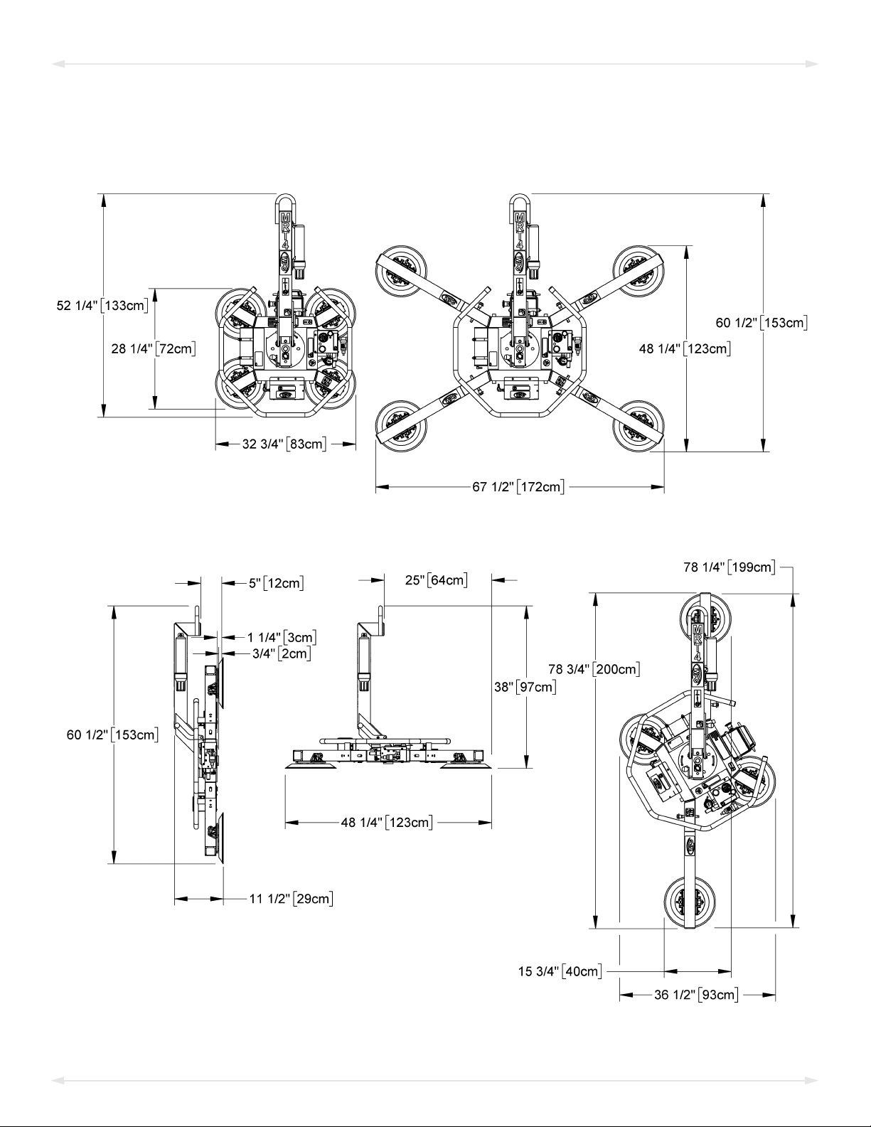
SPECIFICATIONS
Note: A standard MRT411LDC is shown.
MRT4-DC: #35070 Rev 29.0/10-194

SAFETY
Wear personal protective
equipment that is appropriate for
the load material. Follow trade
association guidelines.
Do not remove or obscure safety
labels.
Do not make any modifications to
the lifter (see “LIMITED
WARRANTY”).
Use the lifter only in an approved
“OPERATING ENVIRONMENT” (see
“INTENDED USE”).
Do not use a lifter that is damaged,
malfunctioning, or missing parts.
Do not use a lifter if the sealing
edge of any vacuum pad is cut or
otherwise damaged.
Make sure the contact surfaces of
the load and vacuum pads are clean
before attaching the lifter (see
“MAINTENANCE”).
Position the vacuum pads correctly
on the load before lifting (see
“OPERATION: Positioning the Lifter
on the Load”).
Do not lift a load if any vacuum
indicator shows inadequate
vacuum.
Keep unauthorized personnel away
from the lifter, to avoid injury in
case of an unintended load release.
Do not touch the vacuum release
controls during a lift.
Do not allow people to ride on the
lifter or the load.
Do not use a lifter to lift cracked or
broken glass.
Do not exceed the Maximum
Load Capacity or lift loads the
lifter is not designed for (see
“INTENDED USE”).
Do not use a lifter if the
Maximum Load Capacity or
any safety label appears to be
missing or obscured.
Rev 29.0/10-19 MRT4-DC: #350705
Do not lift a load higher than
necessary or leave suspended loads
unattended.
Do not position a loaded or
unloaded lifter over people.
Before servicing a powered lifter,
place the power control in the
inactive position and, when
possible, disconnect the power source.
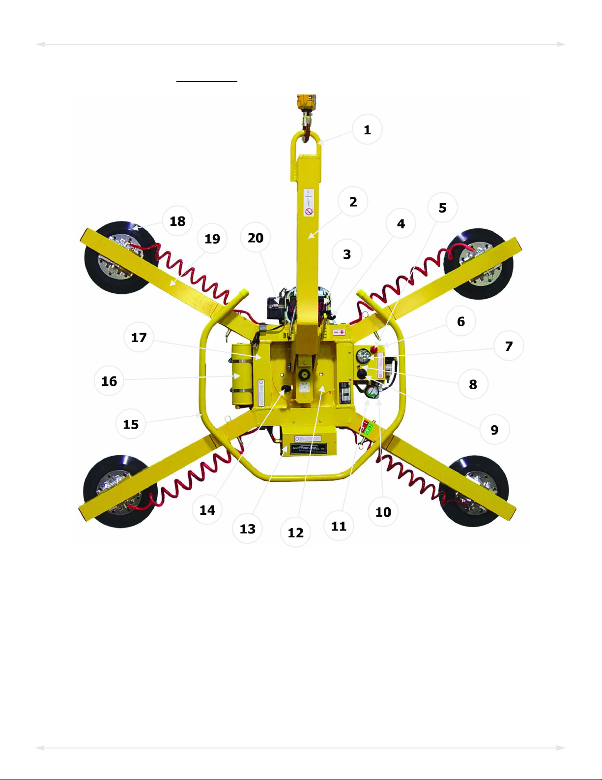
OPERATING FEATURES
Features shown here are underlined on their first appearance in each section following.
1 LIFT POINT 8 BATTERY TEST BUTTON 15 CONTROL HANDLE
2 LIFT BAR 9 LOW VACUUM WARNING BUZZER (optional) 16 VACUUM RESERVE TANK
3 BATTERY 10 VALVE HANDLE 17 PAD FRAME
4 TILT RELEASE LEVER 11 VACUUM GAUGE 18 VACUUM PAD
5 LOW VACUUM WARNING LIGHT 12 ROTATION WEAR PLATE 19 EXTENSION ARM
6 Enclosure with VACUUM SWITCH 13 Cover for VACUUM PUMP 20 BATTERY CHARGER
7 BATTERY GAUGE 14 ROTATION RELEASE LEVER Not shown: INSTRUCTIONS CANISTER
Note: The lifter model MRT411LDC is shown here. Although some of the following photos do not
show this specific lifter, they all illustrate how this kind of lifter functions.
MRT4-DC: #35070 Rev 29.0/10-196
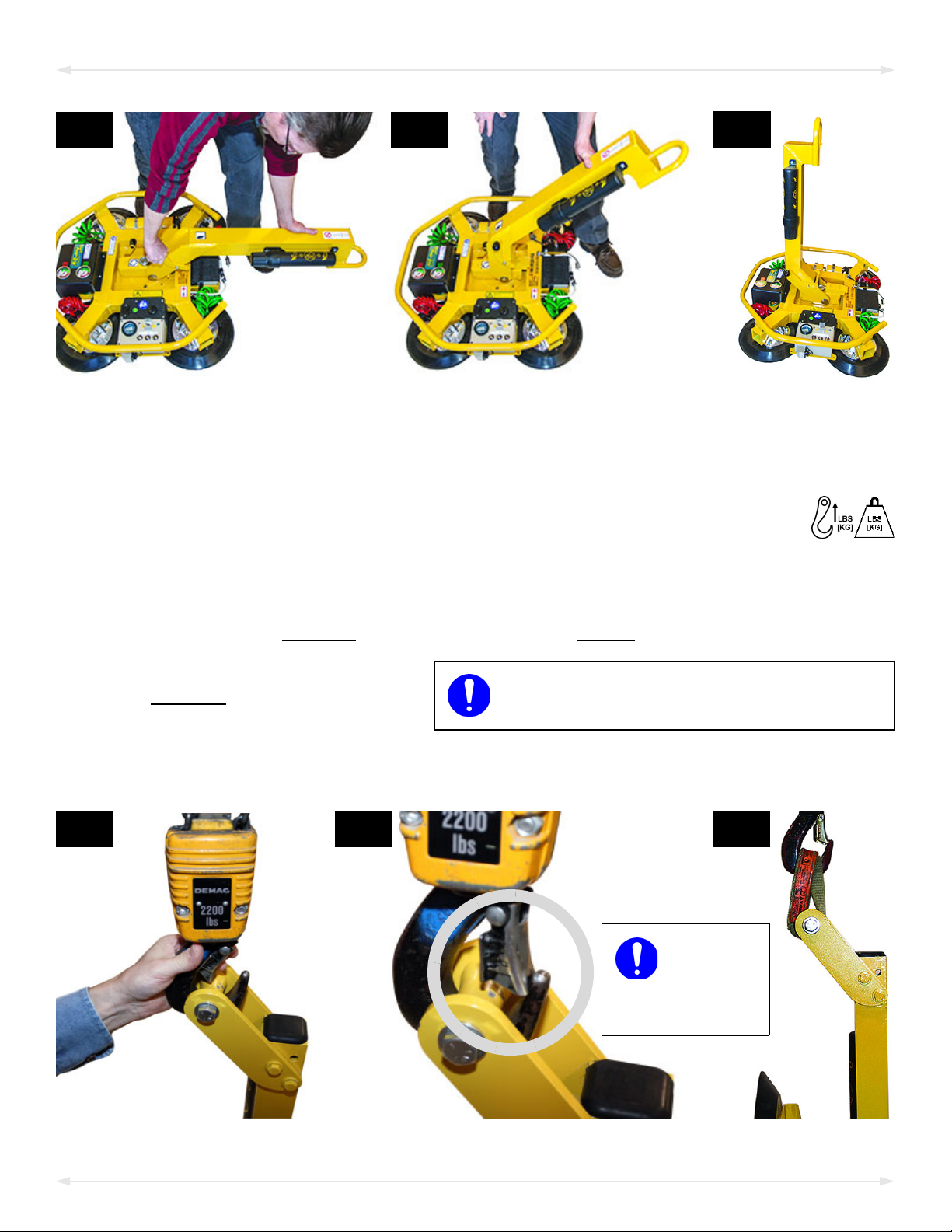
2A 2B
2D 2E
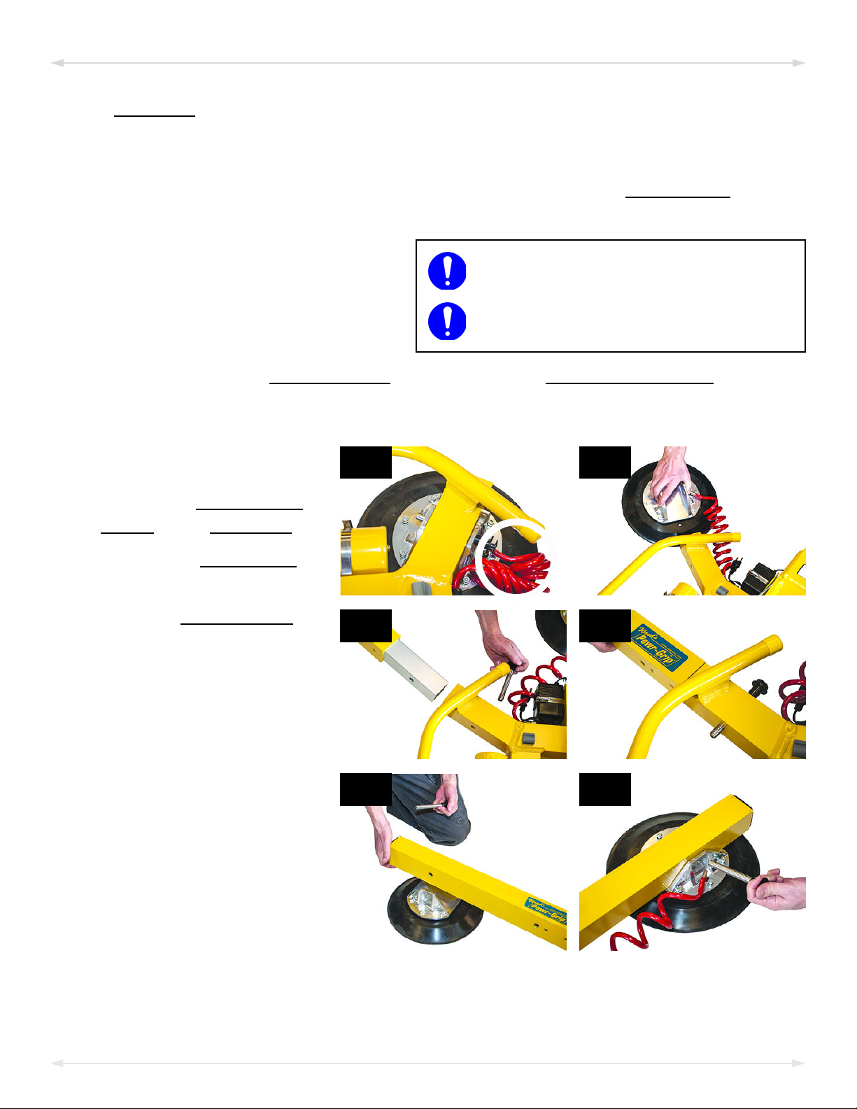
Make
sure hook
has restraining
latch (circled).
2F
Only use rigging rated for Maximum Load
Capacity plus Lifter Weight.
ASSEMBLY
2C
1)
Remove all lifter restraints and save them with the shipping container for future use.
2) Suspend the lifter from appr
Select a crane and/or hoist rated for the Maximum Load Capacity plus the
2.1)
Lifter Weight.
Note: Any lifter use must comply with all statutory or regulatory standards for
ting equipment in your region.
hois
2.2) Disengage any
2.3) Attach the hoisting hook to the
lift point (figs. 2D-E).
rigging (fig. 2F) as needed to
e sure the hook does not
mak
interfere with the load.
tilt locks or latches, and raise the lift bar (figs. 2A-C).
Use
opriate hoisting equipment:
Rev 29.0/10-19 MRT4-DC: #350707
3B3A
3C
3D
4A
ASSEMBLY
2.4) Use the hoisting equipment to remove the lifter from the shipping container. Avoid
damaging the
3)
Connect the electrical connectors (figs. 3A-B and
figs. 3C-D).
vacuum pads.
4)
Assemble the pad frame for optimal load support
(see “T
Remove the pad covers (fig. 4A) and save them for future use.
5) Perform tests as required under “T
O CHANGE THE PAD FRAME CONFIGURATION” on page 9).
ESTING” on page 26).
MRT4-DC: #35070 Rev 29.0/10-198
ASSEMBLY
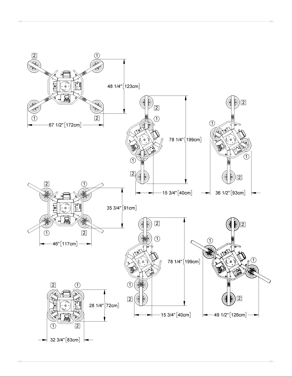
TO CHANGE THE PAD FRAME CONFIGURATION
Rev 29.0/10-19 MRT4-DC: #350709
Use only approved pad frame
configurations.
Securely position vacuum hoses to
avoid damage during lifter operation.
4A 4B
3B
2A
3A
1A
ASSEMBLY
Various pad frame configurations enable the lifter to match different load dimensions. The
illustrations on the preceding page show all approved configurations. Dimensions show Pad
Spread for a standard MRT411LDC(3) lifter (see “SPECIFICATIONS” on page 3 for other models).
Caution: If the lift
circuits (marked “1” and “2” in the preceding illustrations).
Choose an approved configuration to
1)
maximize support across the load
ace and to minimize load overhang
surf
(see “L
page 12).
2) Install or remove the
er is equipped with a dual vacuum system, position the vacuum pads for the 2
OAD CHARACTERISTICS” on
extension arms and reposition the movable pad mounts as needed.
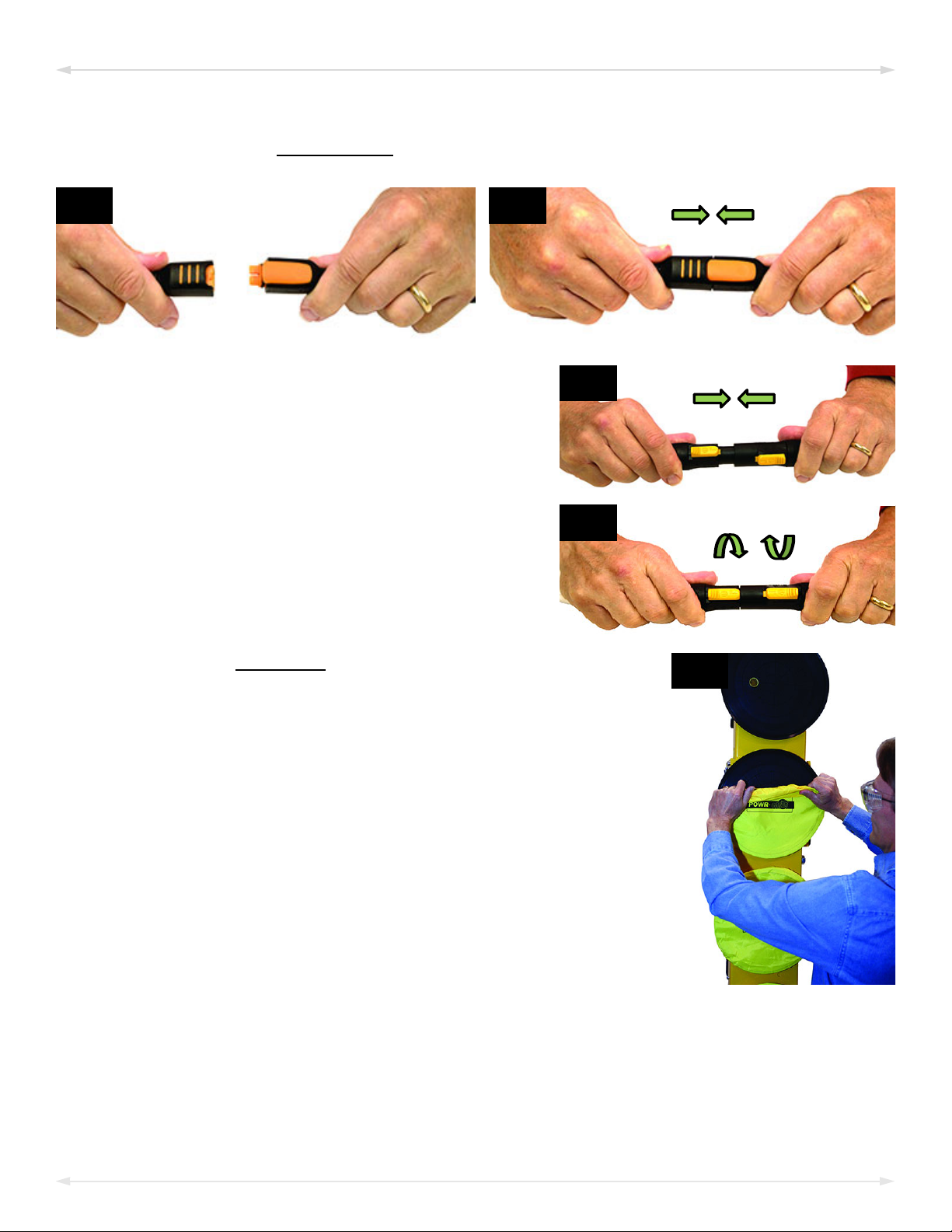
Installing/Removing Extension Arms and Repositioning Vacuum Pads
1)
Remove the cotterless hitch
pin (circled in fig. 1A) that
secur
mount to the pad frame.
2) Remove the
from the pad frame (fig. 2A).
es the
movable pad
vacuum pad
3) Insert the
the pad frame (fig. 3A). Then
insert a cotterless hitch pin
to secure it (fig. 3B).
4) Position the movable pad
moun
(fig. 4A). Then insert a
cotterless hitch pin to secure
it (fig. 4B).
Notes: Repeat or reverse these
teps to configure the pad frame as
s
needed. Store removed
components in a clean, dry
location.
MRT4-DC: #35070 Rev 29.0/10-1910
extension arm into
t on the extension arm
 Loading...