

Page 1
KEEP FOR FUTURE REFERENCE
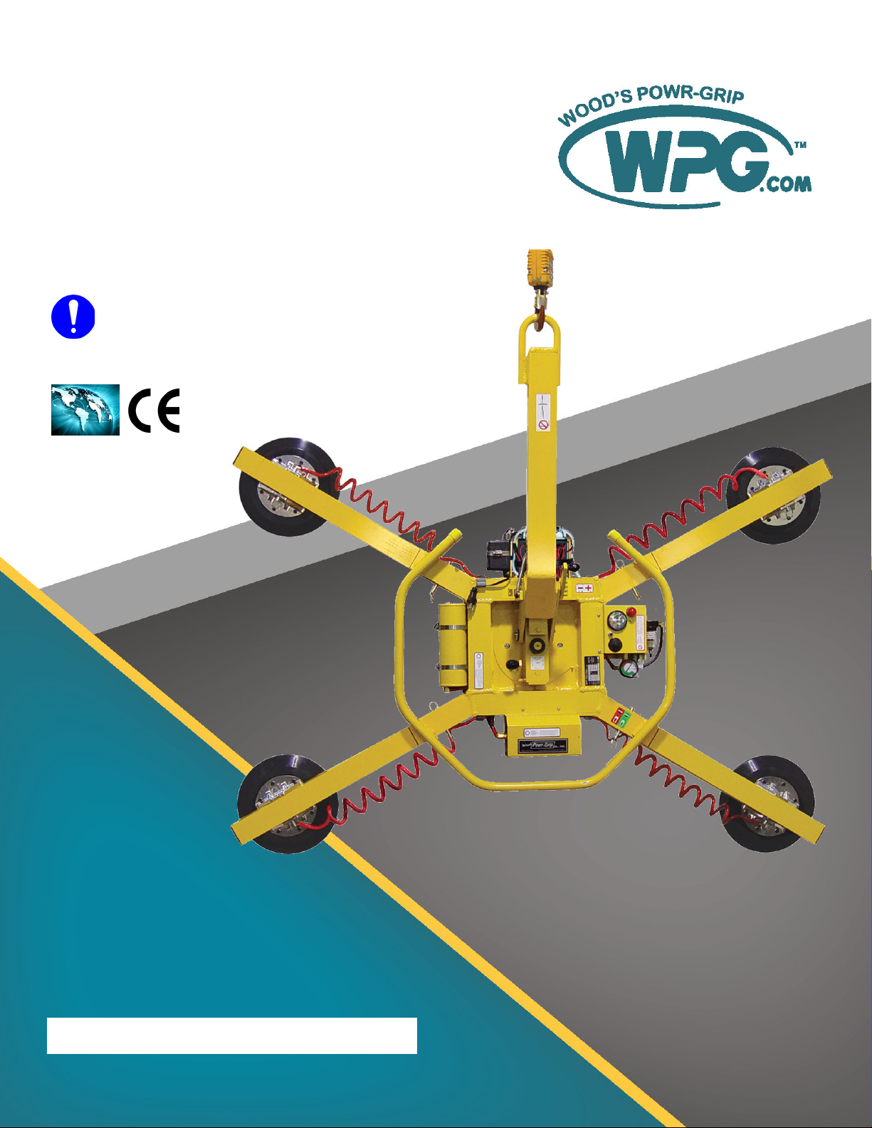
OPERATING
INSTRUCTIONS
INTENDED FOR USE BY SKILLED
PROFESSIONALS • READ AND
UNDERSTAND BEFORE OPERATING
908 W. Main • P.O. Box 368
Laurel, MT USA 59044
800-548-7341 (phone)
406-628-8231 (phone)
406-628-8354 (fax)
www.WPG.com
MANUAL ROTATOR/TILTER,
DC-VOLTAGE
Model numbers: MRT411LDC (shown), MRT49DC,
MRT4HV11DC
Record serial number in blank space above (to locate, see serial
Rev 29.0/10-19 MRT4-DC: #35070i
label on the product).
Page 2

MRT4-DC: #35070 Rev 29.0/10-19ii
Page 3

TABLE OF CONTENTS
SPECIFICATIONS .....................................................................................3
SAFETY...................................................................................................5
OPERATING FEATURES............................................................................6
ASSEMBLY..............................................................................................7
TO CHANGE THE PAD FRAME CONFIGURATION ..................................................9
Installing/Removing Extension Arms and Repositioning Vacuum Pads ............................10
Using Secondary Rotation Stops ....................................................................................... 11
INTENDED USE .....................................................................................12
LOAD CHARACTERISTICS...............................................................................12
OPERATING ENVIRONMENT ..........................................................................13
DISPOSAL OF THE LIFTER .............................................................................13
OPERATION..........................................................................................14
BEFORE USING THE LIFTER...........................................................................14
Taking Safety Precautions .................................................................................................14
Performing Inspections and Tests ..................................................................................... 14
Checking the Battery.........................................................................................................15
TO ATTACH THE PADS TO A LOAD ..................................................................16
Positioning the Lifter on the Load..................................................................................... 16
Sealing the Pads on the Load............................................................................................17
Reading the Vacuum Gauge.............................................................................................. 17
TO LIFT AND MOVE THE LOAD......................................................................18
Interpreting the Warning Light and Optional Warning Buzzer .........................................18
Watching Vacuum Indicators ............................................................................................18
Controlling the Lifter and Load ......................................................................................... 19
In Case of a Power Failure.................................................................................................19
TO ROTATE THE LOAD .................................................................................20
TO TILT THE LOAD ......................................................................................21
TO RELEASE THE PADS FROM THE LOAD .........................................................23
AFTER USING THE LIFTER.............................................................................23
Storing the Lifter............................................................................................................... 23
INSPECTIONS AND TESTS......................................................................25
INSPECTION SCHEDULE ................................................................................25
Rev 29.0/10-19 MRT4-DC: #35070iii
Page 4

TABLE OF CONTENTS
TESTING ...................................................................................................26
Lifter/Load Compatibility Test...........................................................................................26
Operational Tests .............................................................................................................. 27
Vacuum Test......................................................................................................................27
Rated Load Test.................................................................................................................28
MAINTENANCE ....................................................................................29
VACUUM PAD MAINTENANCE.......................................................................29
Pad-to-Load Friction Coefficient .......................................................................................29
Pad Inspection ..................................................................................................................29
Pad Cleaning .....................................................................................................................30
BATT ER Y RECHARGE....................................................................................31
REPLACEMENT PARTS...........................................................................32
LIMITED WARRANTY ............................................................................33
TO OBTAIN REPAIRS OR WARRANTY SERVICE...................................................33
MRT4-DC: #35070 Rev 29.0/10-19iv
Page 5

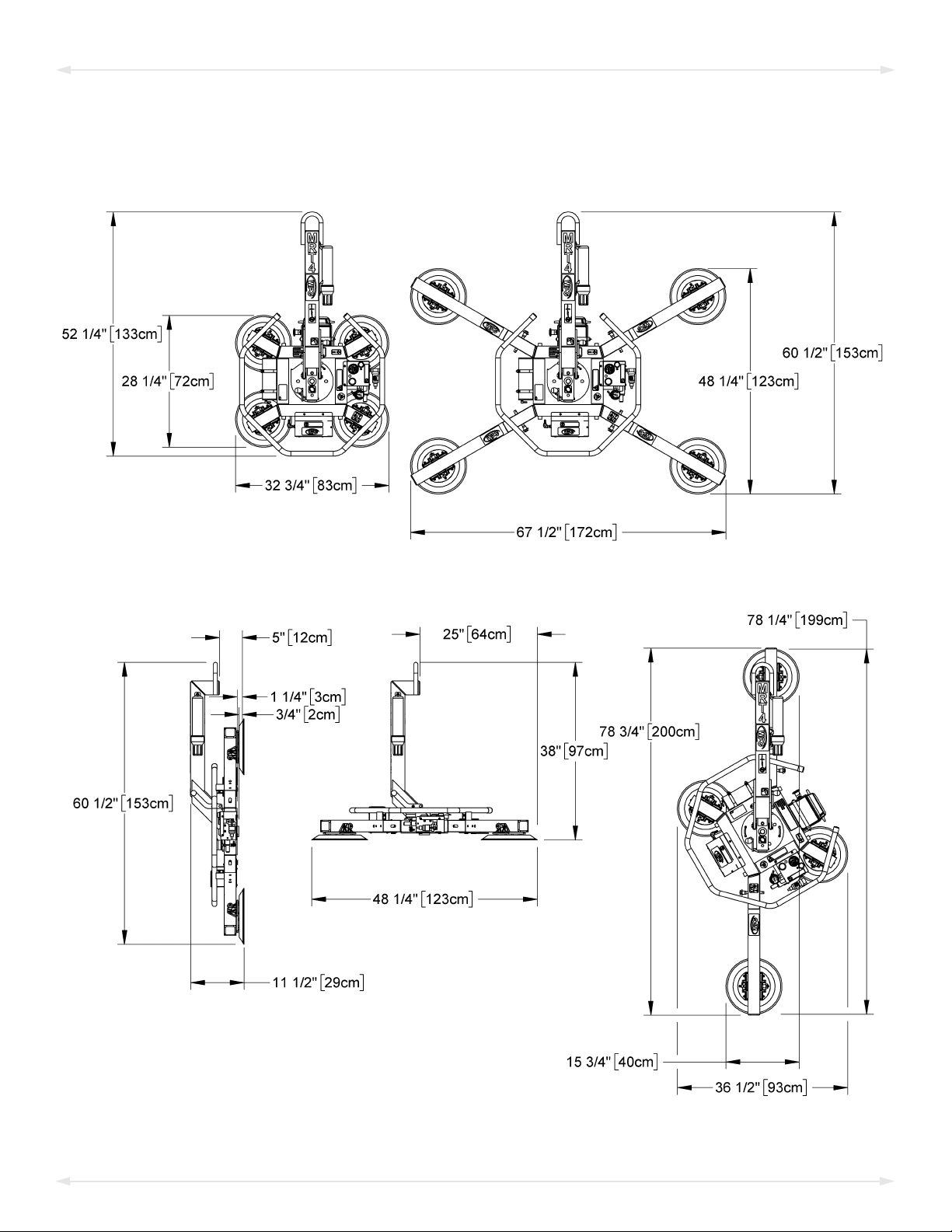
SPECIFICATIONS
Product
Description
Model
Number
Vacuum Pads
(4 each, standard rubber)
Pad Spread
Length ‒ Maximum
Length ‒ Minimum
Width ‒ Maximum
Width ‒ Minimum
Maximum Load
Capacity
Per-Pad
Weight
Power
System
Battery
Capacity
Rotation
Capability
Capability
Product
Options
Operating
Elevation
Operating
Temperatures
Service
ASME Standard
BTH-1
Total
Lifter
Tilt
Life
Designed for use with hoisting equipment, MRT4-DC lifters support loads using vacuum and manipulate
loads using manual 360° rotation and manual 90° tilt motions.
MRT49DC MRT4HV11DC MRT411LDC
1
2
9" [23 cm] nom. diameter
(Model VPFS9)
---------------------------- (to outer edges) ----------------------------
10" [25 cm] nom. diameter,
lipped (Model HV11)
11" [28 cm] nom. diameter,
lipped (Model G3370)
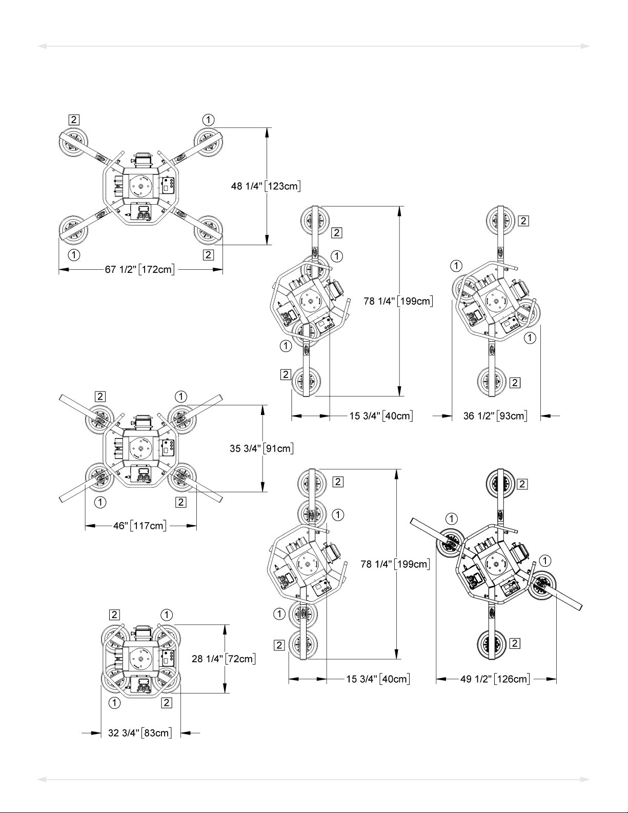
75¼" [192 cm] 77¼" [197 cm] 78¼" [199 cm]
29¾" [76 cm] 31¾" [81 cm] 32¾" [83 cm]
46½" [119 cm] 48½" [124 cm] 49½" [126 cm]
12¾" [33 cm] 14¾" [38 cm] 15¾" [40 cm]
3
125 lbs [56.5 kg] 150 lbs [68 kg] 175 lbs [80 kg]
500 lbs [225 kg] 600 lbs [270 kg] 700 lbs [320 kg]
135 lbs [62 kg]
12 volts DC, 3.5 amps
7 amp-hours
Manual, 360°, with latching at each ¼ turn (when required)
Manual, 90°, with automatic locking in vertical position
See separate instructions about options.
Up to 6,000' [1,828 m]
32° — 104° F [0° — 40° C]
20,000 lifting cycles, when used and maintained as intended
4
Design Category "B", Service Class "0" (see www.WPG.com for more information)
1...... Available with other rubber compounds for special purposes (see www.WPG.com).
2...... The illustrations under “T
3...... The Maximum Load Capacity is rated at a vacuum of 16" Hg [-54 kPa] on clean, smooth, nonporous flat surfaces with a friction coefficient of 1. Pad
compound, load rigidity, strength, surface conditions, overhang, angle, center of gravity and temperature can also affect the lifting capacity. A “qualified
person” should evaluate the effective lifting capacity for each use (see definition under “Rated Load Test” on page 28).
4...... Vacuum pads, filter elements and other wear-out items are excluded.
O CHANGE THE PAD FRAME CONFIGURATION” on page 9 show the Pad Spread for all approved pad frame configurations.
!!–CE–!! This symbol appears only when a CE Standard is different from other applicable standards. CE requirements are
mandatory in the European Union, but may be optional elsewhere.
Rev 29.0/10-19 MRT4-DC: #350703
Page 6
SPECIFICATIONS
Note: A standard MRT411LDC is shown.
MRT4-DC: #35070 Rev 29.0/10-194
Page 7
SAFETY
Wear personal protective
equipment that is appropriate for
the load material. Follow trade
association guidelines.
Do not remove or obscure safety
labels.
Do not make any modifications to
the lifter (see “LIMITED
WARRANTY”).
Use the lifter only in an approved
“OPERATING ENVIRONMENT” (see
“INTENDED USE”).
Do not use a lifter that is damaged,
malfunctioning, or missing parts.
Do not use a lifter if the sealing
edge of any vacuum pad is cut or
otherwise damaged.
Make sure the contact surfaces of
the load and vacuum pads are clean
before attaching the lifter (see
“MAINTENANCE”).
Position the vacuum pads correctly
on the load before lifting (see
“OPERATION: Positioning the Lifter
on the Load”).
Do not lift a load if any vacuum
indicator shows inadequate
vacuum.
Keep unauthorized personnel away
from the lifter, to avoid injury in
case of an unintended load release.
Do not touch the vacuum release
controls during a lift.
Do not allow people to ride on the
lifter or the load.
Do not use a lifter to lift cracked or
broken glass.
Do not exceed the Maximum
Load Capacity or lift loads the
lifter is not designed for (see
“INTENDED USE”).
Do not use a lifter if the
Maximum Load Capacity or
any safety label appears to be
missing or obscured.
Rev 29.0/10-19 MRT4-DC: #350705
Do not lift a load higher than
necessary or leave suspended loads
unattended.
Do not position a loaded or
unloaded lifter over people.
Before servicing a powered lifter,
place the power control in the
inactive position and, when
possible, disconnect the power source.
Page 8
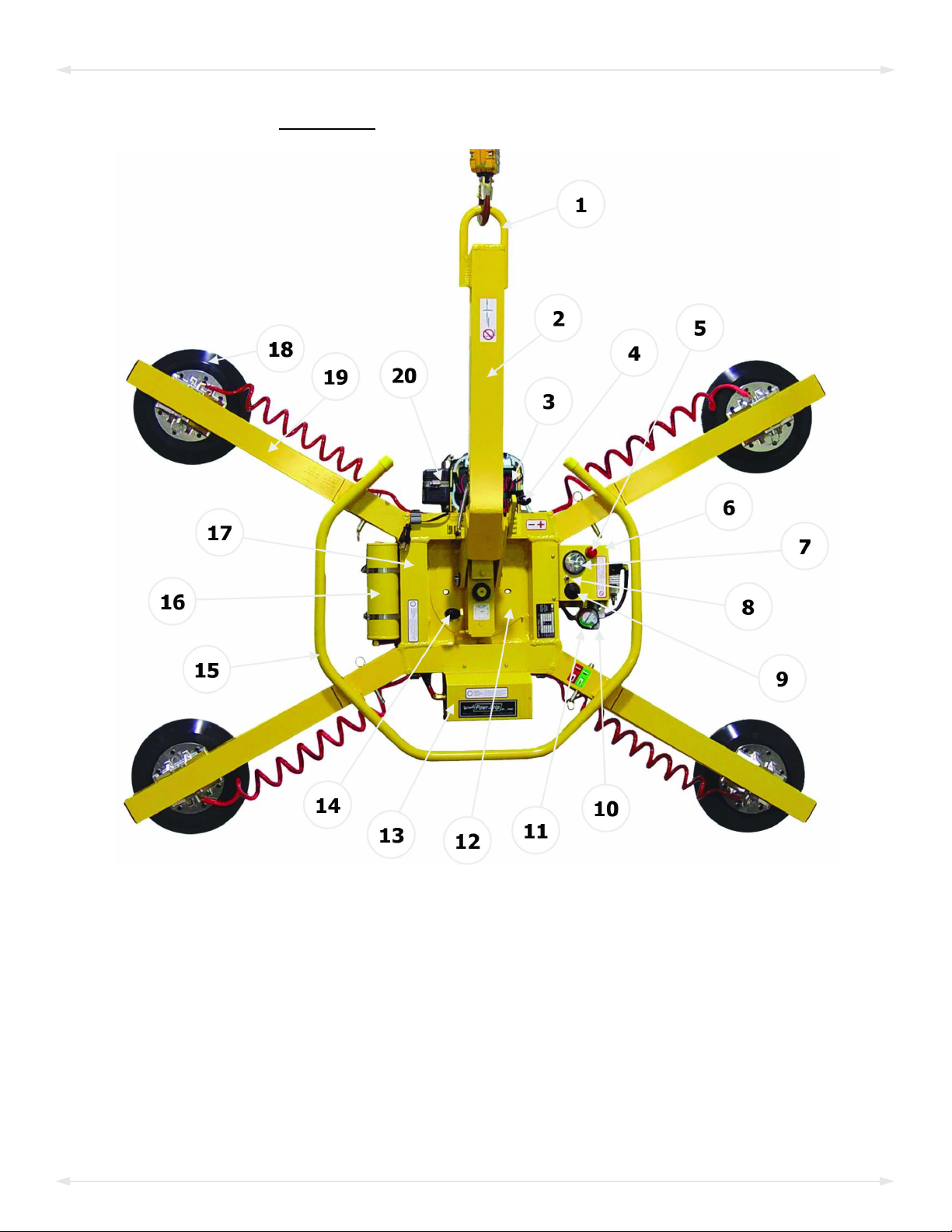
OPERATING FEATURES
Features shown here are underlined on their first appearance in each section following.
1 LIFT POINT 8 BATTERY TEST BUTTON 15 CONTROL HANDLE
2 LIFT BAR 9 LOW VACUUM WARNING BUZZER (optional) 16 VACUUM RESERVE TANK
3 BATTERY 10 VALVE HANDLE 17 PAD FRAME
4 TILT RELEASE LEVER 11 VACUUM GAUGE 18 VACUUM PAD
5 LOW VACUUM WARNING LIGHT 12 ROTATION WEAR PLATE 19 EXTENSION ARM
6 Enclosure with VACUUM SWITCH 13 Cover for VACUUM PUMP 20 BATTERY CHARGER
7 BATTERY GAUGE 14 ROTATION RELEASE LEVER Not shown: INSTRUCTIONS CANISTER
Note: The lifter model MRT411LDC is shown here. Although some of the following photos do not
show this specific lifter, they all illustrate how this kind of lifter functions.
MRT4-DC: #35070 Rev 29.0/10-196
Page 9
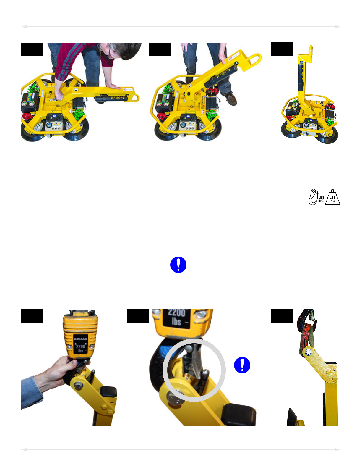
2A 2B
2D 2E
Make
sure hook
has restraining
latch (circled).
2F
Only use rigging rated for Maximum Load
Capacity plus Lifter Weight.
ASSEMBLY
2C
1)
Remove all lifter restraints and save them with the shipping container for future use.
2) Suspend the lifter from appr
Select a crane and/or hoist rated for the Maximum Load Capacity plus the
2.1)
Lifter Weight.
Note: Any lifter use must comply with all statutory or regulatory standards for
ting equipment in your region.
hois
2.2) Disengage any
2.3) Attach the hoisting hook to the
lift point (figs. 2D-E).
rigging (fig. 2F) as needed to
e sure the hook does not
mak
interfere with the load.
tilt locks or latches, and raise the lift bar (figs. 2A-C).
Use
opriate hoisting equipment:
Rev 29.0/10-19 MRT4-DC: #350707
Page 10
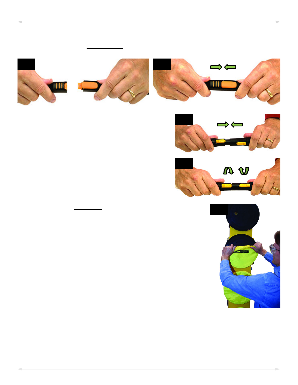
3B3A
3C
3D
4A
ASSEMBLY
2.4) Use the hoisting equipment to remove the lifter from the shipping container. Avoid
damaging the
3)
Connect the electrical connectors (figs. 3A-B and
figs. 3C-D).
vacuum pads.
4)
Assemble the pad frame for optimal load support
(see “T
Remove the pad covers (fig. 4A) and save them for future use.
5) Perform tests as required under “T
O CHANGE THE PAD FRAME CONFIGURATION” on page 9).
ESTING” on page 26).
MRT4-DC: #35070 Rev 29.0/10-198
Page 11
ASSEMBLY
TO CHANGE THE PAD FRAME CONFIGURATION
Rev 29.0/10-19 MRT4-DC: #350709
Page 12
Use only approved pad frame
configurations.
Securely position vacuum hoses to
avoid damage during lifter operation.
4A 4B
3B
2A
3A
1A
ASSEMBLY
Various pad frame configurations enable the lifter to match different load dimensions. The
illustrations on the preceding page show all approved configurations. Dimensions show Pad
Spread for a standard MRT411LDC(3) lifter (see “SPECIFICATIONS” on page 3 for other models).
Caution: If the lift
circuits (marked “1” and “2” in the preceding illustrations).
Choose an approved configuration to
1)
maximize support across the load
ace and to minimize load overhang
surf
(see “L
page 12).
2) Install or remove the
er is equipped with a dual vacuum system, position the vacuum pads for the 2
OAD CHARACTERISTICS” on
extension arms and reposition the movable pad mounts as needed.
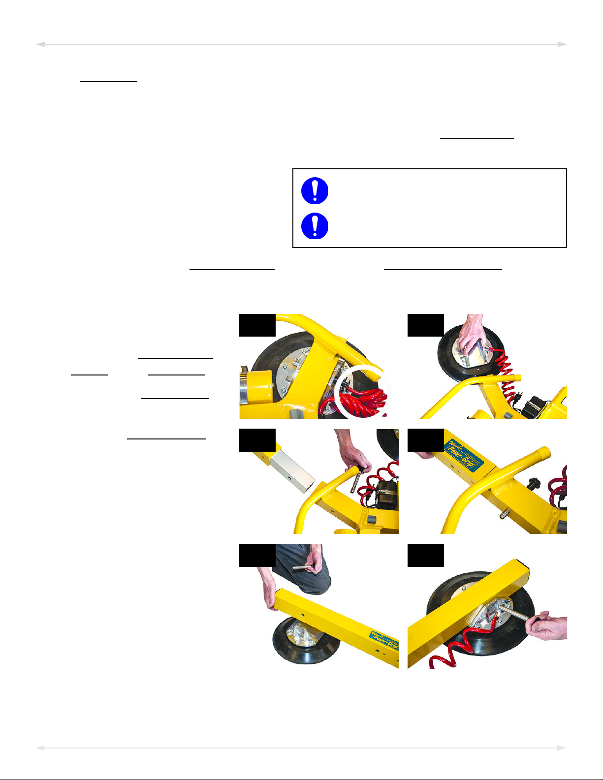
Installing/Removing Extension Arms and Repositioning Vacuum Pads
1)
Remove the cotterless hitch
pin (circled in fig. 1A) that
secur
mount to the pad frame.
2) Remove the
from the pad frame (fig. 2A).
es the
movable pad
vacuum pad
3) Insert the
the pad frame (fig. 3A). Then
insert a cotterless hitch pin
to secure it (fig. 3B).
4) Position the movable pad
moun
(fig. 4A). Then insert a
cotterless hitch pin to secure
it (fig. 4B).
Notes: Repeat or reverse these
teps to configure the pad frame as
s
needed. Store removed
components in a clean, dry
location.
MRT4-DC: #35070 Rev 29.0/10-1910
extension arm into
t on the extension arm
Page 13

1A 1B
1C 1D
ASSEMBLY
Using Secondary Rotation Stops
Align the secondary rotation stops for correct use of the pad frame in long, narrow
configurations:
1) Loosen the 2 screws
2) Rotate the wear plate to align with the sec
3) Tighten the screws secur
Note: Reverse these steps to reali
Rev 29.0/10-19 MRT4-DC: #3507011
that secure the rotation wear plate (fig. 1A).
ondary rotation stops (figs. 1B-C).
ely (circled in fig. 1D).
gn the primary rotation stops.
Page 14

INTENDED USE
Do NOT lift explosives, radioactive
substances or other hazardous materials.
LOAD CHARACTERISTICS
Make sure the vacuum lifter is intended
to handle each load acc
requirements:
ording to these
• The load weight must not e
• The load must be a single piece of r
relatively smooth contact surface.
xceed the Maximum Load Capacity.
elatively nonporous material with a flat and
1, 2
To determine whether the load is too
porous or rough, perform a “Lifter/Load Compatibility Test” on page 26.
• The load's contact surface must be able t
o obtain a friction coefficient of 1 with the lifter's
vacuum pads (see “Pad-to-Load Friction Coefficient” on page 29). Otherwise, the
capacity should be derated appropriately.
• The load's surface temperature must
not exceed the Operating Temperatures.
3
• The load's minimum length and width are determined by the current Pad Spread
(see “SPECIFICATIONS” on page 3).
• The load's ma
• 1" [2.5 cm] is the allowable thickness at Maximum Load Capacity.
ximum length and width are determined by its allowable overhang.
5
Note: Standard vacuum pads can stain or deform load surfaces with light colors or soft
coatings. Test such surfaces for damaging effects before using the lifter on them.
6
4
1..... Although concave vacuum pads can also attach to some curved loads, curvature can reduce lifting capacity. Contact WPG for more information.
2..... A “single piece” of material includes curtainwall assemblies, unitized glazing systems and similar construction units.
3..... Vacuum pads made from a heat-resistant rubber compound can e
authorized dealer for more information.
4..... The allowable overhang is the amount of load material that can extend sideways beyond the vacuum pad without breaking or otherwise being
damaged. This depends on the load material, its thickness, and the angle of handling (if any). Since every material has different physical
properties, the allowable overhang must be evaluated separately for each load type. Contact WPG or an authorized dealer for more
information.
5..... However, the allowable thickness increases as load
6..... Alternative rubber compounds are available for these purposes. C
MRT4-DC: #35070 Rev 29.0/10-1912
weight decreases. Contact WPG for more information.
nable you to lift loads with higher surface temperatures. Contact WPG or an
ontact WPG or an authorized dealer for more information.
Page 15

Never use lifter in dangerous
environments.
Metal particles and similar
environmental contaminates
could result in vacuum pump failure.
Moisture can result in
reduced lifting capacity.
INTENDED USE
OPERATING ENVIRONMENT
Make sure the vacuum lifter is intended for use in each work environment, given the following
restrictions:
This lifter is not intended for any environment
•
that is dangerous to the operator or damaging
o the lifter. Avoid environments containing
t
explosives, caustic chemicals and other
dangerous substances.
• The work environment is limited by the Oper
Temperatures.
• The lifter is not designed to be watertight.
use it in rain or other
1, 2
unsuitable conditions.
ating Elevation and Operating
Do not
DISPOSAL OF THE LIFTER
After the Service Life of the vacuum lifter has ended (see “SPECIFICATIONS” on page 3), dispose
of it in compliance with all local codes and applicable regulatory standards.
Note: Special disposal regulations may apply to the
battery.
1..... Although lifter use may be possible at higher elevation, lifting capacity is reduced whenever the lifter is unable to attain vacuum in the green
range on the vacuum gauge. Contact WPG for more information.
2..... Special provisions may allow the lifter to operate outside the specified temperature range. Contact WPG for more information.
Rev 29.0/10-19 MRT4-DC: #3507013
Page 16

OPERATION
Read all directions and safety rules before using
lifter.
Always wear appropriate personal protective
equipment.
Examine air filter regularly
and service when needed.
1A
Make sure warning buzzer can be heard over noise at operator
position.
BEFORE USING THE LIFTER
Determine whether the vacuum lifter is capable of each intended task (see “SPECIFICATIONS”
on page 3 and “INTENDED USE” on page 12). Then complete the f
Taking Safety Precautions
•
Be trained in all industry
and regulatory standards
or lifter operation in your
f
region.
• Follow trade association
ollowing preparations:
guidelines about pr
ecautions needed for each load material.
Performing Inspections and Tests
• Follow the “INSPECTION SCHEDULE” on page 25 and “TESTING” on page 26.
Service the air filter whenever the bowl contains
•
liquid or other contaminates, or the element
ars dirty (see “A
appe
SERVICE MANUAL).
If the lifter has a low vacuum warning buzzer (fig. 1A), make sure it is
•
clearly audible at the maximum dis
the lifter, despite any barriers or obstacles.
IR FILTER MAINTENANCE” in
tance between the operator and
1, 2
1..... Maximum alarm volume is 103 dBA at 2' [60 cm]. If CE Standards apply, consult EN 7731 to make sure the warning buzzer is compliant.
2..... The “Vacuum Test” on page 27 provides a convenient opportunity to check this.
MRT4-DC: #35070 Rev 29.0/10-1914
Page 17

Always check battery energy before
every lift.
OPERATION
Checking the Battery
Use the battery gauge to determine whether the battery needs to be charged (see “BATTE RY
ECHARGE” on page 31).
R
1
Never use the lifter unless battery energy appears in the green range.
• While the
valve handle is in the “attach” position ( / power on), the battery gauge
automatically shows battery energy.
• While the valve handle is in the
“release” position (
use the
battery test button (circled)
to check the battery energy.
/ power off),
3
2
1..... If the pump is running or the battery charger is connected to an AC power source, the reading on the battery gauge will not be accurate.
2..... After the vacuum pump stops running, the battery gauge requires a few moments to stabilize before it shows an accurate energy level.
3..... If the lifter has not been used since the battery was charged, the battery gauge may falsely show a high energy level. This “surface charge”
dissipates after the pump runs for about 1 minute, allowing the gauge to show accurate energy.
Rev 29.0/10-19 MRT4-DC: #3507015
Page 18

1A
2A
Consult the Per-Pad
Load Capacity.
OPERATION
TO ATTACH THE PADS TO A LOAD
Make sure the contact surfaces of the load and vacuum pads are clean (see
“Pad Cleaning” on page 30).
Positioning the Lifter on the Load
1)
Center the pad frame on
the load (fig. 1A).
1
2)
Make sure all vacuum pads
will fit on the load and will
be loaded ev
3) Place the vacuum pads in
contact with the load
surface.
1..... The lifter is designed to handle the maximum load weight when the load’s center of gravity is positioned within 2" [5 cm] of the lifter’s rotation
axis. Uncentered loads may rotate or tilt unexpectedly.
enly (fig. 2A).
MRT4-DC: #35070 Rev 29.0/10-1916
Page 19

1A
Keep valve handle in “attach” position
throughout lift.
1B 1C
OPERATION
Sealing the Pads on the Load
Pull the valve handle outward until it latches (circled
in fig. 1A) in the “attach” position (
The vacuum pump will turn on, the low vacuum
warning light will remain lit and the low vacuum warning buzzer, if present, will sound until the
vacuum pads seal. This is normal.
Press the lifter firmly against the load t
).
o help the pads begin to seal.
1
Reading the Vacuum Gauge
A vacuum gauge shows the current vacuum level in positive inches of Hg and negative kPa:
Green range (>16" Hg [-54 kPa]):
•
Vacuum level is sufficient to lift the
ximum load weight (fig. 1B).
ma
• Re
d range (<16" Hg [-54 kPa]):
Vacuum level is not sufficient to lift
the maximum load weight (fig. 1C).
If it takes more than 5 seconds for the
cuum level to reach 5" Hg [-17 kPa], press
va
on any
Once the pads have sealed, the lifter should be able t
except when used above the maximum Operating Elevation.
vacuum pad that has not yet sealed.
o maintain sufficient vacuum for lifting,
2
If it does not:
• Make sure the
• When necessary, perform the “Vacuum Test” on page 27.
vacuum switch is adjusted correctly (see SERVICE MANUAL).
1..... Although a vacuum pad may become distorted during shipping or storage, this condition should correct itself with continued use.
2..... If the lifter is used above the maximum Operating Elevation (see “SPECIFICATIONS” on page 3), it may not be able to maintain sufficient vacuum
for lifting. Contact WPG for more information.
Rev 29.0/10-19 MRT4-DC: #3507017
Page 20

Lift bar must be vertical to lift
load.
Never lift load unless warning devices turn off, because
this could result in load release and personal injury.
Make sure vacuum indicators remain
completely visible.
1A
Stay clear of any suspended load while
indicators warn of low vacuum.
OPERATION
TO LIFT AND MOVE THE LOAD
Interpreting the Warning Light and Optional Warning Buzzer
When the vacuum
lifter is ready to lift
the Ma
Capacity, the
battery energy.
ximum Load
vacuum pump and the low vacuum warning light turn off temporarily, to conserve
When air leaks into the vacuum system, the vacuum pump turns on and of
warning light) as necessary to maintain sufficient vacuum for lifting.
Note: The low vacuum warning buzzer, if present, turns on and off together with the warning
light.
f (along with the
Watching Vacuum Indicators
Watch the low vacuum warning light and the vacuum
gauge (fig. 1A) throughout the entire lift.
If the warning light turns on and the vacuum gauge
shows a level less than 16" Hg [-54 kPa]:
1) Keep everyone away from a suspended load un
it can be safely lowered to a stable support.
til
2) Stop using the lifter until the cause of the vacuum loss can be identified: Conduct the
“Pad Inspection” on page 29 and perform the “Vacuum Test” on page 27.
3) Correct any faults before resuming nor
MRT4-DC: #35070 Rev 29.0/10-1918
mal operation of the lifter.
Page 21

1A
Stay clear of any suspended
load during power failure.
OPERATION
Controlling the Lifter and Load
When the lifter is ready, use the hoisting equipment to raise
the lifter and load as needed.
Use the
and load in the required position.
Once there is enough clearance, y
required.
control handle (circled in fig. 1A) to keep the lifter
ou may move the load as
In Case of a Power Failure
A vacuum reserve tank helps maintain vacuum temporarily in the event of a battery failure or
electrical system failure. Although the lifter is designed to support the load for at least 5
minutes without power, this depends on many factors, including the “L
page 12 and the condition of the
If a power failure occurs, keep everyone away from a
suspended load until it can be safely lowered to a stable
support. Corr
operation of the lifter.
ect any faults before resuming normal
vacuum pads (see “VACUUM PAD MAINTENANCE” on page 29).
OAD CHARACTERISTICS” on
Rev 29.0/10-19 MRT4-DC: #3507019
Page 22

2A
3A
Make sure load is positioned correctly on
lifter (as previously directed).
Never disengage rotation and tilt latches at
the same time, because this could result in
load damage or personal injury.
Unbalanced loads may rotate unexpectedly
when rotation latch is disengaged.
OPERATION
TO ROTATE THE LOAD
1)
Make sure the load has enough
clearance to rotate without
ontacting anyone or anything.
c
2) Use the
in fig. 2A) to keep the load
under control at all times.
3) Pull the
(fig. 3A) to disengage the
rotation latch, and rotate the load as required.
4) To stop load motion, let go of the rotatio
stop.
Note: Whenever rotation is not required, keep the rot
damage or personal injury.
control handle (circled
rotation release lever
n release lever and guide the load to the next
ation latch engaged, to prevent load
MRT4-DC: #35070 Rev 29.0/10-1920
Page 23

2A
3A
Make sure load is positioned correctly on
lifter (as previously directed).
Never disengage rotation and tilt latches at
the same time, because this could result in
load damage or personal injury.
Unbalanced loads may rotate unexpectedly
when rotation latch is disengaged.
OPERATION
TO TILT THE LOAD
1)
Make sure the load has enough
clearance to tilt without
ntacting anyone or anything.
co
2) Use the
in fig. 2A) to keep the load
under
3) If the
the
disengage the tilt latch.
Note: The pad frame automatically latches when tilt
4) Tilt the load as required.
Note: See “Load Characteristics” on page 12 about allowable load overhang.
control handle (circled
control at all times.
pad frame is latched, pull
tilt release lever (fig. 3A) to
ed t
o the vertical position.
Rev 29.0/10-19 MRT4-DC: #3507021
Page 24

1A
A load with overhang
may force you to release
control handle as
the
the load approaches the
flat position. In this
case, use hand cups
(circled in fig. 1A) or
other appropriate
means to control the
load.
OPERATION
MRT4-DC: #35070 Rev 29.0/10-1922
Page 25

Make sure load is at rest and fully supported
before releasing vacuum pads.
1A
Do not move lifter until pads release completely, because such movement could
result in load damage or personal injury.
OPERATION
TO RELEASE THE PADS FROM THE LOAD
1) Press the lever to release the latch and push the valve
handle inward (fig. 1A) to the “release” position ( ).
2) Before you lift another load, perform the Every-Lift Inspection (see “INSPECTION SCHEDULE”
on page 25).
AFTER USING THE LIFTER
1) Leave the valve handle in the “release” position ( / power off).
2) Charge the
3) Use the hoisting equipment to lower the vacuum lifter gently onto a stable support. Then
detach the hoisting hook from the
Caution: Do not se
4) To transport the lifter, secure it in the or
restraints or equivalent.
battery after each workday as needed (see “BAT TE RY RECHARGE” on page 31).
lift point.
t the lifter on surfaces that could soil or damage vacuum pads.
iginal shipping container with the original
Storing the Lifter
1) 1BUse the pad covers supplied (fig. 1B) to keep the vacuum
pads clean.
1
1..... To maximize battery life, charge it promptly after each use.
Rev 29.0/10-19 MRT4-DC: #3507023
Page 26

3A 3B
3C 3D 3E
OPERATION
!!–CE–!! To prevent the lifter from tipping over on relatively horizontal surfaces, place the
vacuum pads facedown on a clean, smooth, flat surface. Then lower the
support under the
2) Charge the battery completely and repeat every 6 months (see “BATTE RY RECHARGE” on
page 31).
lift point.
lift bar and place a
3) Disconnect the electrical connectors (figs. 3A-B and figs. 3C-E) to prevent battery
discharge.
4) Store the lifter in a clean, dry loc
Avoid storage above 100° F [38° C.]
ation. Store the battery between 32° and 70° F [0-21° C].
MRT4-DC: #35070 Rev 29.0/10-1924
Page 27

INSPECTIONS AND TESTS
INSPECTION SCHEDULE
Perform inspections according to the following frequency schedule. If any fault is found, correct
it and perform the next most frequent inspection before using the vacuum lifter.
Note: If a lifter is used less than 1 day in a 2-week period, perform the Periodic Inspection before using it.
1
Action Every Lift
Examine vacuum pads for contaminates or damage (see
“Pad Inspection” on page 29).
Frequent
(every 20-40 hrs)
Periodic
(every 250-400 hrs)
Examine load surface for contaminates or debris.
Examine controls and indicators for damage.
Check
Battery” on page 15).
battery for adequate charge (see “Checking the
Examine lifter’s structure for damage.
Examine vacuum system for damage (including
pads, fittings and hoses).
Examine
air filter for conditions requiring service (see
“AIR FILTER MAINTENANCE” in SERVICE MANUAL).
vacuum
Perform “Vacuum Test” on page 27.
Check for unusual vibrations or noises while operating lifter.
2
Examine entire lifter for evidence of:
• looseness, excessive wear or excessive corrosion
• deformation, cracks, dents to structural or functional
ponents
com
• cuts in vacuum pads or hoses
• any other hazardous conditions
Inspect entire electrical syste
m for damage, wear or
contamination that could be hazardous, in compliance
with all local codes and regulatory standards.
Caution: Use appropriate cleaning methods for each
electrical part, as specified by codes and standards.
Improper cleaning can damage parts.
1...... The Frequent Inspection is also required whenever the lifter has been out of service for 1 month or more.
2...... The Periodic Inspection is also required whenever the lifter has been out of service for 1 year or more. Keep a written record of all Periodic Inspections. If
necessary, return the lifter to WPG or an authorized dealer for repair (see “LIMITED WARRANTY” on page 33).
Rev 29.0/10-19 MRT4-DC: #3507025
Page 28

Take precautions in case
load should fall during test.
INSPECTIONS AND TESTS
TESTING
Perform the following test to determine whether or not a load surface is too porous or rough:
Lifter/Load Compatibility Test
1
1) Make sure the vacuum generating system is functioning correctly (see “Vacuum Test” on
page 27).
2) Thoroughly clean the load surf
page 30).
2
3) Place the load in the upright position on a stable support.
ace and the vacuum pads (see “Pad Cleaning” on
3
4) Attach the vacuum pads to the load as previously directed.
5) After the
SING THE LIFTER” on page 23).
U
6)
Raise the load a minimal distance, to make sure it
vacuum pump stops running, disconnect the battery connector (see “AFTER
4
is supported by the lifter.
7) Watch each
vacuum gauge: Starting from a
vacuum level of 16" Hg [-54 kPa], the lifter must maintain a vacuum level greater than
5
12" Hg [-41 kPa] for 5 minutes.
If not, lifting this load requires additional precautions
(eg, a load sling). Contact WPG for more information.
8) Lower the load aft
1..... The “Pad-to-Load Friction Coefficient” can affect the outcome of this test (see page 29).
2..... Contaminated loads can cause the vacuum pump to run frequently or continuously. Since excessive pumping quickly reduces battery energy,
clean the load whenever possible.
3..... For Flat Lifters, place the load in the flat position.
4..... Move the valve handle to the “release” position (power
5..... Under CE requirements, the lift
MRT4-DC: #35070 Rev 29.0/10-1926
er 5 minutes or before the vacuum level diminishes to 12" Hg [-41 kPa].
off) before reconnecting the battery.
er must maintain a vacuum level greater than 8" [-27 kPa].
Page 29

Take precautions in case
load should fall during test.
Never use a lifter that has
failed test.
INSPECTIONS AND TESTS
Perform the following tests before placing the lifter in service initially, following any repair,
when directed in the “I
NSPECTION SCHEDULE”, or whenever necessary:
Operational Tests
Test all features and functions of the lifter (see “OPERATING FEATURES” and “OPERATION”).
Vacuum Test
1) Clean the face of each vacuum pad (see “Pad Cleaning” on page 30).
Use a test load with weight equal to the Maximum Load Capacity, a clean, smooth,
2)
nonporous surface and other appropriate “L
OAD CHARACTERISTICS” (see page 12).
3) Attach the lifter to the test load as previously directed. After the vacuum pump stops
running, the vacuum level should appear in the green range on the
see “V
Raise the load a minimal distance and disconnect
4)
the
on page 23).
ACUUM SWITCH ADJUSTMENT” in SERVICE MANUAL).
battery connector (see “AFTER USING THE LIFTER”
2
vacuum gauge (if not,
1
5) Watch the vacuum gauge: The vacuum level should not decrease by more than 4" Hg
[-14 kPa] in 5 minutes.
Lower the load after 5 minutes or whenever a
6)
lifter fails the test, and r
elease the load as
previously directed.
7) Qualified service personnel must correct any f
can be returned to service.
1..... The load surface should have either a flat surface or no more curvature than the lifter is designed for, if any.
2..... Move the valve handle to the “release” position (power off) before reconnecting the battery.
3..... For more information, search for you
r lifter’s Model Number at www.WPG.com and select the “Troubleshooting” link on the product page.
3
ault in the vacuum system before the lifter
Rev 29.0/10-19 MRT4-DC: #3507027
Page 30

Take precautions in case
load should fall during test.
Never use a lifter that has
failed test.
INSPECTIONS AND TESTS
Rated Load Test
The following steps must be performed or supervised by a qualified person:
1
2
1) Use a test load that weights 125% (± 5%) of the Maximum Load Capacity and has
the appropriate “L
2)Attach the
osition the load to produce the gr
3) P
vacuum pads to the load as previously directed.
OAD CHARACTERISTICS” (see page 12).
eatest stress on the lifter consistent with “INTENDED
USE” on page 12.
Raise the load a minimal distance and leave it
4)
suspended for 2 minutes.
5) Once the t
est is complete
d, lower the load for
release as previously directed.
Inspect the lifter for any stress damage, and
6)
repair or replace components as necessary to
successfully pass the t
est.
epare a written report of the tes
7) Pr
t and keep it on file.
1..... An equivalent simulation may also be used. Contact WPG for more information.
2..... A “qualified person” has successfully demonstrated the ability to solve problems relating to the subject matter and work, either by possessing a
recognized degree in an applicable field or a certificate of professional standing, or by possessing extensive knowledge, training and experience.
MRT4-DC: #35070 Rev 29.0/10-1928
Page 31

MAINTENANCE
Replace any pad that has damaged
sealing edges.
1A
Notes: Refer to SERVICE MANUAL #36110 when applicable. See final section for wiring
diagrams.
VACUUM PAD MAINTENANCE
Pad-to-Load Friction Coefficient
The friction coefficient represents the lifter's ability to resist load slippage.1 The
Maximum Load Capacity is based on a friction c
oefficient of 1, as determined by testing
of clean, new, standard rubber
used under any other conditions, a qualified person must first determine the effective lifting
capacity.
Long-term exposure to heat, chemicals or UV light can reduce the friction coefficient of vacuum
pads. Replace pads every 2 years or more often, when necessary.
2
vacuum pads on clean, dry, regular glass. If the lifter is
Pad Inspection
Inspect each vacuum pad (fig. 1A) according to
the “I
correct the following faults before using the
lifter (see “REPLACEMENT PARTS”, when
applicable):
NSPECTION SCHEDULE” on page 25 and
• Contaminates on the face (1) or sealing
es (2).
edg
• Filter screen (3) missing from face.
• Nicks, cuts or abrasions in sealing edg
es.
• Wear, stiffness or glaze.
1..... Not applicable to Flat Lifters.
2..... A “qualified person” has successfully demonstrated the ability to solve problems relating to the subject matter and work, either by possessing a
recognized degree in an applicable field or a certificate of professional standing, or by possessing extensive knowledge, training and experience.
Rev 29.0/10-19 MRT4-DC: #3507029
Page 32

Pad Cleaning
1A
Never use harsh chemicals on
vacuum pad.
Never use rubber conditioners on
vacuum pad.
1)
Regularly clean the face of each
vacuum pad (fig. 1A), using soapy
water or other mild cleansers to
remove oil, dust and other
contaminates.
Solvents, petroleum-based products
(including kerosene, gasoline and
diesel fuel) or other harsh chemicals
can damage vacuum pads.
MAINTENANCE
Many rubber conditioners can leave a
hazardous film on vacuum pads.
2) Prevent liquid from entering the v
face.
3) Wipe the pad face clean, using a clean spong
4) Allow the pad to dry completely before using the lifter.
acuum system through the suction hole on the pad
e or lint-free cloth to apply the cleanser.
1
1..... A brush with bristles that do not harm rubber can help remove contaminates clinging to sealing edges. If these cleaning methods are not
successful, contact WPG or an authorized dealer for assistance.
MRT4-DC: #35070 Rev 29.0/10-1930
Page 33

Make sure power source has ground fault circuit
interrupter.
MAINTENANCE
BATTERY RECHARGE
Charge the battery whenever the battery gauge shows reduced energy. Caution: Make sure
valve handle is in “release” position ( / power off).
Identify the input voltage
marked on the
charger, and plug it in to an
appropriate power source.
The power lamp (Ф) turns on when the charger is functioning. Consult the six-stage display to
determine the charging status. The battery can be used after stage 3 and is fully charged at
stage 5.
Normally, the battery should take no more than 8 hours to charge completely.
the following faults:
Power lamp (Ф) flashes:
•
Charger is not
nnected to battery;
co
reconnect charger (see
“ASSEMBLY” on page 8).
• Error lamp (!) turns on
immedia
battery
tely: Battery
1
2
If not, check for
leads connected to
wrong poles; reverse
battery leads.
• Charging stops at stage
1 or 4, and err
(!) turns on: Battery is
no longer functioning; replace battery (see “REPLACEMENT PARTS” on page 32).
Before you return the lifter to service, r
1..... Any external power supply must conform to all applicable local codes. This lifter is not intended for use while the charger is connected to AC
power.
2..... The charger automatically reduces the charging rate when the battery is fully charged.
Rev 29.0/10-19 MRT4-DC: #3507031
or lamp
echeck the battery as previously directed.
Page 34

REPLACEMENT PARTS
Stock No. Description Qty.
65441 Vacuum Hose ‒ 0
65440 Vacuum Hose ‒ 0
65014 Pad Spring ‒ W
65010 Pad Spring ‒
64716 Battery Charger ‒ 0.8
64715 Battery Charger ‒ 0.8
64714 Battery Charger ‒ 0.8
64664 Battery ‒ 12 V
64283 Bulb ‒ 13
59086NC Battery Connector ‒ Twin
59028 Movable Pad Mount ‒ 2-1/
54390NC Power Lead 1
53120 Pad Fitting ‒ Elbow
53114 Hose Fitting ‒ Co
49646T Vacuum Pad ‒ Model
49605T Vacuum Pad ‒ Model
49506TA Vacuum Pad ‒ Model
49180 End Plug ‒ 3"
49150 End Plug ‒ 2-1
36110 Service Manual — 12V DC, — 1 SFCM — Single Vacuum System
29353 Pad Cover 4
15792 Tilt or Rotation Release Lever Knob 2
15632 Pad Filter Screen ‒ Sm
15630 Pad Filter Screen ‒ Large (for
13532 Cotterless Hitch Pin ‒
10900 Shoulder Bolt ‒ So
V ‒ Bayonet (for low vacuum warning light) 1
.245" ID x 3/8" OD x 48" Length ‒ Coiled 4
.245" ID x 3/8" OD *
ave Type (for HV11 pad) 4
Coil Type (for VPFS9 & G3370 pads) 4
Amp ‒ 240 V AC ‒ Australian Type 1
Amp ‒ 240 V AC 1
Amp ‒ 100 / 120 V AC 1
DC ‒ 7 Amp-Hours 1
Lead 1
2" Tubing Size 4
‒ 3/64" ID 4
upler ‒ 1/4" Barb 4
G3370 / 11" [28 cm] Diameter ‒ Lipped 4
HV11 / 10" [25 cm] Diameter ‒ Lipped 4
VPFS9 / 9" [23 cm] Diameter 4
x 3" x 1/4" Tubing Size 1
/2" x 2-1/2" x 1/4" Tubing Size 4
— Manual Valve 1
all (for VPFS9 pad) 4
G3370 & HV11 pads) 4
1/2" x 3-3/8" 8
cket Head ‒ 5/16" x 1/2" x 1/4-20 Thread (for mounting pads) 24
*Length as required; vacuum hose is sold by the foot (approx. 30.5 cm).
See SERVICE MANUAL #36110 for additional parts.
ERVICE ONLY WITH IDENTICAL REPLACEMENT PARTS,
S
AVAIL ABLE AT WPG.COM OR THROUGH AN AUTHORIZED WPG DEALER
MRT4-DC: #35070 Rev 29.0/10-1932
Page 35

LIMITED WARRANTY
Wood's Powr-Grip Co., Inc.
908 West Main St.
Laurel, MT 59044 USA
406-628-8231 (phone)
800-548-7341 (phone)
406-628-8354 (fax)
Wood's Powr-Grip® (WPG) products are carefully constructed, thoroughly inspected at various
stages of production, and individually tested. They are warranted to be free from defects in
workmanship and materials for a period of one year from the date of purchase.
If a problem develops during the warranty period, f
warranty service. If inspection shows that the problem is due to defective workmanship or
materials, WPG will repair the product without charge.
Warranty does not apply when ...
• modifications have been made to the pr
• rubber portions have been cut or scr
• repairs are required due to abnormal w
• the product has been damag
If a problem is not covered under warranty, WPG will notif
repair. If the customer agrees to pay all repair costs and to receive the repaired product on a
C.O.D. basis, WPG then will proceed with repairs.
ed, misused or neglected.
ollow the instructions below to obtain
oduct after leaving the factory
atched during use;
ear and tear, and/or;
y the customer of costs prior to
TO OBTAIN REPAIRS OR WARRANTY SERVICE
For purchases in North America:
Contact the WPG Technical Service Department. When f
complete product – prepaid – along with your name, address and phone number to the street
address listed at the bottom of this page. WPG may be reached by phone or fax numbers listed
below.
For purchases in all other loc
Contact your dealer or the WPG T
reached by phone or fax numbers listed below.
alities:
echnical Service Department for assistance. WPG may be
actory service is required, ship the
Rev 29.0/10-19 MRT4-DC: #3507033
Page 36

MRT4-DC: #35070 Rev 29.0/10-1934
Page 37

Rev 29.0/10-19 MRT4-DC: #3507035
Page 38

MRT4-DC: #35070 Rev 29.0/10-1936
 Loading...