

WOSON LUB909 Operation Manual

Handpiece Lubricating System
LUB909
Operation Manual
NINGBO JIANGBEI WOSON MEDICAL INSTRUMENT CO., LTD.

Handpiece Lubricating System
Operation Manual Page 2 of 12
Content
Ⅰ Basic Features ........................................................................... 3
Ⅱ Parameters ................................................................................. 3
Ⅲ Structure of Handpiece Lubricating System ................................ 3
IV Installation Components ............................................................ 4
Ⅴ Operation Procedure .................................................................. 5
Ⅵ Disassembling and Installation of Front Door Cover ................... 8
Ⅶ Maintenance ............................................................................... 8
Ⅷ Failure Recovery ...................................................................... 10
Ⅸ Precautions .............................................................................. 11
Handpiece Lubricating System
Operation Manual Page 3 of 12
Dear Customer:
Thank you for choosing Handpiece Lubricating System LUB909. The machine can make easy and safe
cleaning and oiling on the Handpiece. Please read carefully the manual for maintenance.
Ⅰ Basic Features
1. Ensure the cleansing and oiling of stomatology handpieces .
2. Can serve three handpieces at the same time .
3. The rotation gear of LUB909 can make effective cleaning and oiling for the handpiece in different angles.
4. Press “Air” button after cleaning and oiling to remove residual oil.
5. Short, long or extremely long mode can be selected according to the handpieces.
6. The mist filter cotton can reduce the diffusion of the mist to the smallest extent.
Ⅱ Parameters
1.Type:LUB909
2. Rated Voltage: AC220V/50Hz, AC110V/60Hz
3. Fuse(220V/240V:F1A ~250V)
4. Air Pressure: 0.35~0.60Mpa (3.5~6.0kgf/cm2) (50~80psi)
5. Capacity of Oil Container: 350mL
6. Weight: 8 kg
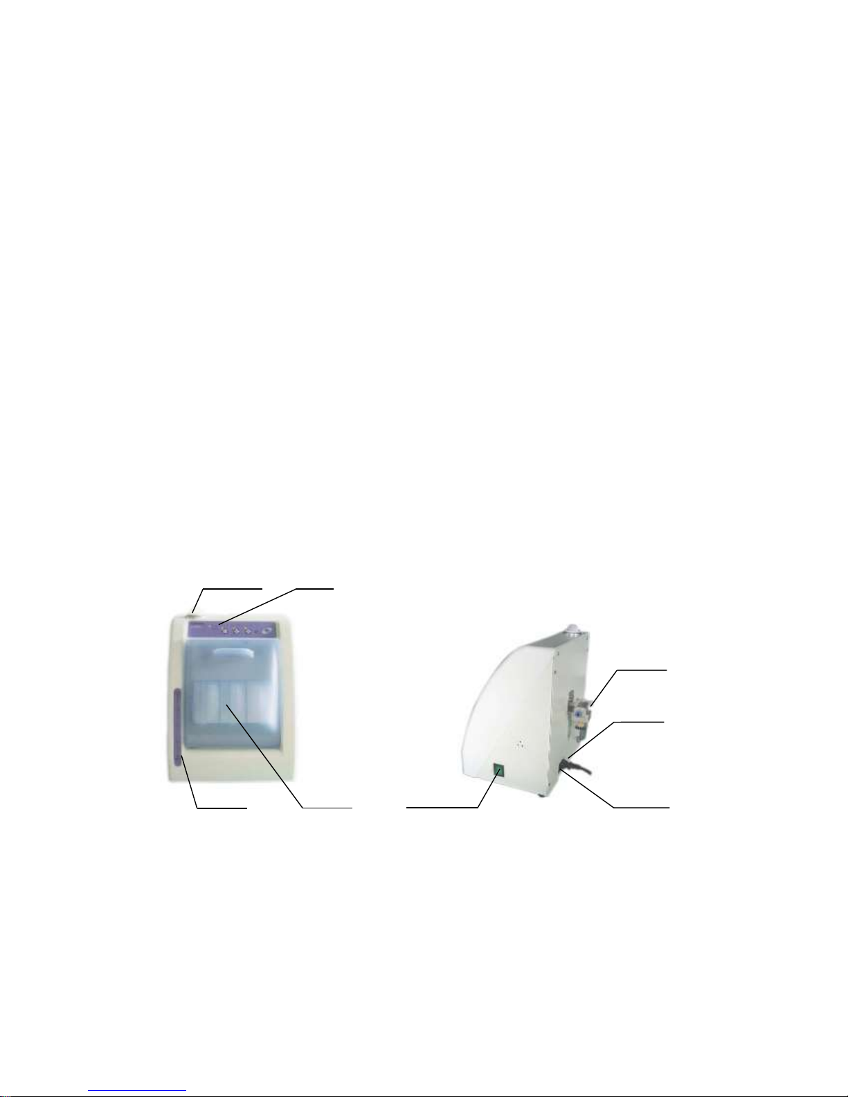
Ⅲ Structure of Handpiece Lubricating System
Accessories
Pic 2
Pic 1
Panel
Oiling Cap
Door Cover
Oil Level Meter
Power Switch
Air Filter
Fuse Box
Power Input
Handpiece Lubricating System
Operation Manual Page 4 of 12
All the products are provided with accessories. Please contact your distributor if any of the accessories is
missed as detailed in Table 1.
Table 1
S/N
Pic
Name
Unit
Qty
Remark
1 Power Line
line
1
2 Maintenance Oil
Kettle 1
3 Oil Hopper
Piece 1
4 Mist Filter Cotton
Piece
12
5 Air Pipe
Line 1 3m
6 O-type Ring
Piece 4
7 Oil Sorbent Cotton
Pack
1
20 Slices
8 3-ways Connection
Piece 1
IV Installation Components
1. Rated Fuse
Follow the bellowing Table 2 to check whether the voltage is the same with rated fuse. See 7. (5)
Replacement of fuse in “Maintenance” (Pic 19 to 21) to check the rated value of the fuse.
Table 2
Voltage
Rated Fuse
220V
F1A 250V
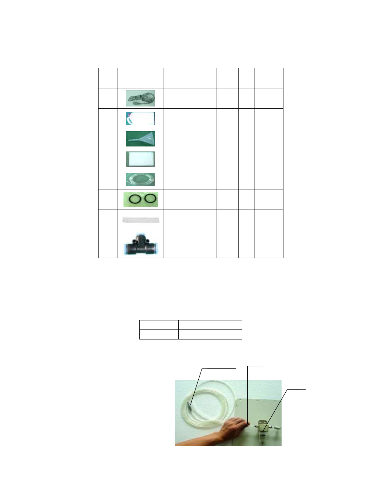
Connect To Air Compressor
2.Connect the air pipe and put the
end of air tube to the quick coupling
of the air filter, and the other end
connected to air compressor (As
shown in Pic 3)
To Air Compressor
Air Pipe
Air Filter
Pic 3
 Loading...