

Page 1
SAFETY AND OPERATING MANUAL
ORIGINAL INSTRUCTIONS
Mini CirCular Saw wu420
Page 2

2
General power tool safety warnings
Warning: Read all safety warnings and all instructions.
Failure to follow the warnings and instructions may result in electric
shock, fire and/or serious injury.
Save all warnings and instruc tions for future reference.
The term “power tool” in the warnings refers to your mains-operated
(corded) power tool or battery-operated (cordless) power tool.
1
WORK AREA SAFETY
a) Keep work area clean and well lit. Cluttered or dark areas invite
accidents.
b) Do not operate power tools in explosive atmospheres, such
as in the presence of flammable liquids, gases or dust. Power
tools create sparks which may ignite the dust or fumes.
c) Keep children and bystanders away while operating a power
tool. Distractions can cause you to lose control.
2
ELECTRICAL SAFETY
a) Power tool plugs must match the outlet. Never modify the
plug in any way. Do not use any adapter plugs with earthed
(grounded) power tools. Unmodified plugs and matching outlets
will reduce risk of electric shock.
b) Avoid body contact with earthed or grounded surfaces,
such as pipes, radiators, ranges and refrigerators. There is an
increased risk of electric shock if your body is earthed or grounded.
c) Do not expose power tools to rain or wet conditions. Water
entering a power tool will increase the risk of electric shock.
d) Do not abuse the cord. Never use the cord for carrying, pulling
or unplugging the power tool. Keep cord away from heat,
oil, sharp edges or moving parts. Damaged or entangled cords
increase the risk of electric shock.
e) When operating a power tool outdoors, use an extension cord
suitable for outdoor use. Use of a cord suitable for outdoor use
reduces the risk of electric shock.
f) If operating a power tool in a damp location is unavoidable,
use a residual current device (RCD) protected supply. Use of an
RCD reduces the risk of electric shock.
3
PERSONAL SAFETY
a) Stay alert, watch what you are doing and use common sense
when operating a power tool. Do not use a power tool while
you are tired or under the influence of drugs, alcohol or
medication. A moment of inattention while operating power tools
may result in serious personal injury.
b) Use personal protective equipment. Always wear eye
protection. Protective equipment such as dust mask, non-skid
safety shoes, hard hat, or hearing protection used for appropriate
conditions will reduce personal injuries.
c) Prevent unintentional starting. Ensure the switch is in the
off-position before connecting to power source and/or battery
pack, picking up or carrying the tool. Carrying power tools with
your finger on the switch or energising power tools that have the
switch on invites accidents.
d) Remove any adjusting key or wrench before turning the power
tool on. A wrench or a key left attached to a rotating part of the
power tool may result in personal injury.
e) Do not overreach. Keep proper footing and balance at all
times. This enables better control of the power tool in unexpected
Page 3

3
situations.
f) Dress properly. Do not wear loose clothing or jewellery. Keep
your hair, clothing and gloves away from moving parts. Loose
clothes, jewellery or long hair can be caught in moving parts.
g) If devices are provided for the connection of dust extraction
and collection facilities, ensure these are connected and
properly used. Use of dust collection can reduce dust-related
hazards.
f) Keep cutting tools sharp and clean. Properly maintained cutting
tools with sharp cutting edges are less likely to bind and are easier
to control.
g) Use the power tool, accessories and tool bits etc. in
accordance with these instructions, taking into account the
working conditions and the work to be performed. Use of the
power tool for operations different from those intended could result
in a hazardous situation.
4
POWER TOOL USE AND CARE
a) Do not force the power tool. Use the correct power tool for
your application. The correct power tool will do the job better and
safer at the rate for which it was designed.
b) Do not use the power tool if the switch does not turn it on and
off. Any power tool that cannot be controlled with the switch is
dangerous and must be repaired.
c) Disconnect the plug from the power source and/or the battery
pack from the power tool before making any adjustments,
changing accessories, or storing power tools. Such preventive
safety measures reduce the risk of starting the power tool
accidentally.
d) Store idle power tools out of the reach of children and do
not allow persons unfamiliar with the power tool or these
instructions to operate the power tool. Power tools are
dangerous in the hands of untrained users.
e) Maintain power tools. Check for misalignment or binding of
moving parts, breakage of parts and any other condition that
may affect the power tool’s operation. If damaged, have the
power tool repaired before use. Many accidents are caused by
poorly maintained power tools.
5
SERVICE
a) Have your power tool serviced by a qualified repair person
using only identical replacement parts. This will ensure that the
safety of the power tool is maintained.
b) If the replacement of the supply cord is necessary, this has to
be done by the manufacturer or his agent in order to avoid a
safety hazard.
Additional safety rules for your
circular saw
1
Always wear a dust mask, hearing protection and eye protection.
2
Only use saw blades recommended in the specification.
3
Do not use any abrasive wheels.
4
Use only blade diameter(s) in accordance with the markings.
SAFETY WARNINGS FOR ALL SAWS
a) DANGER: Keep hands away from cutting area and the
blade. If both hands are holding the saw, they cannot be cut by the
blade.
Page 4

4
b) Do not reach underneath the workpiece. The guard cannot
protect you from the blade below the workpiece.
c) Adjust the cutting depth to the thickness of the workpiece.
Less than a full tooth of the blade teeth should be visible below the
workpiece.
d) Never hold piece being cut in your hands or across your
leg. Secure the workpiece to a stable platform. It is important
to support the work properly to minimize body exposure, blade
binding, or loss of control.
e) Hold power tool by insulated gripping surfaces when
performing an operation where the cutting tool may contact
hidden wiring or its own cord. Contact with a “live” wire will
also make exposed metal parts of the power tool “live” and shock
the operator.
f) When ripping always use a rip fence or straight edge guide.
This improves the accuracy of cut and reduces the chance of blade
binding.
g) Always use blades with correct size and shape (diamond
versus round) of arbor holes. Blades that do not match the
mounting hardware of the saw will run eccentrically, causing loss
of control.
h) Never use damaged or incorrect blade washers or bolt. The
blade washers and bolt were specially designed for your saw, for
optimum performance and safety of operation.
FURTHER SAFET Y INSTRUCTIONS FOR ALL SAWS
KICKBACK CAUSES AND RELATED WARNINGS:
• Kickback is a sudden reaction to a pinched, bound or misaligned
saw blade, causing an uncontrolled saw to lift up and out of the
workpiece toward the operator.
• When the blade is pinched or bound tightly by the kerf closing
down, the blade stalls and the motor reaction drives the unit
rapidly back toward the operator.
• If the blade becomes twisted or misaligned in the cut, the teeth
at the back edge of the blade can dig into the top surface of the
wood causing the blade to climb out of the kerf and jump back
toward the operator.
• Kickback is the result of saw misuse and/or incorrect operating
procedures or conditions and can be avoided by taking proper
precautions as given below.
a) Maintain a firm grip on the saw and position your arm to
resist kickback forces. Position your body to either side of the
blade, but not in line with the blade. Position the hand not
holding the saw well away from the travel path of the saw.
Kickback could cause the saw to jump backwards, but kickback
forces can be controlled by the operator, if proper precautions are
taken.
b) When blade is binding, or when interrupting a cut for any
reason, release the trigger and hold the saw motionless in
the material until the blade comes to a complete stop. Never
attempt to remove the saw from the work or pull the saw
backward while the blade is in motion or kickback may occur.
Investigate and take corrective actions to eliminate the cause of
blade binding.
c) When restarting a saw in the workpiece, center the saw
blade in the kerf and check that saw teeth are not engaged
into the material. If saw blade is binding, it may walk up or
kickback from the workpiece as the saw is restarted.
d) Support large panels to minimize the risk of blade pinching
and kickback. Large panels tend to sag under their own weight.
Page 5

5
Supports must be placed under the panel on both sides, near the
line of cut and near the edge of the panel.
e) Do not use dull or damaged blades. Unsharpened or
improperly set blades produce narrow kerf causing excessive
friction, blade binding and kickback.
f) Blade depth and bevel adjusting locking levers must be
tight and secure before making cut. If blade adjustment shifts
while cutting, it may cause binding and kickback.
g) Use extra caution when making a “plunge cut” into
existing walls or other blind areas. The protruding blade may
cut objects that can cause kickback.
SAFETY INSTRUCTIONS FOR PLUNGE- TYPE SAW
a) Check guard for proper closing before each use. Do not
operate the saw if guard does not move freely and enclose
the blade instantly. Never clamp or tie the guard with the
blade exposed. If saw is accidentally dropped, guard may be bent.
Check to make sure that guard moves freely and does not touch
the blade or any other part, in all angles and depths of cut.
b) Check the operation and condition of the guard return
spring. If the guard and the spring are not operating properly,
they must be serviced before use. Guard may operate sluggishly
due to damaged parts, gummy deposits, or a build-up of debris.
c) Assure that the guide plate of the saw will not shift while
performing the “plunge cut” when the blade bevel setting
is not at 90°. Blade shifting sideways will cause binding and likely
kick back.
d) Always observe that the guard is covering the blade before
placing saw down on bench or floor. An unprotected, coasting
blade will cause the saw to walk backwards, cutting whatever is
in its path. Be aware of the time it takes for the blade to stop after
switch is released.
GENERAL SAFETY WARNINGS FOR YOUR LASER
WARNING: Read all safety warnings and all instructions.
Failure to follow the warnings and instructions may result in serious
injury.
Save all warnings and instruc tions for future reference.
These lasers do not normally present an optical hazard although
staring at the beam may cause flash blindness.
Do not stare directly at the laser beam. A hazard may exist if you
deliberately stare into the beam, please observe all safety rules as
follows:
1
The laser shall be used and maintained in accordance with the
manufacturer’s instructions.
2
Never aim the beam at any person or an object other than the work
piece.
3
The laser beam shall not be deliberately aimed at another person
and shall be prevented from being directed towards the eye of a
person for longer than 0.25 seconds area.
4
Always ensure the laser beam is aimed at a sturdy work piece
without reflective surfaces, e.g. wood or rough-coated surfaces
are acceptable. Bright shiny reflective sheet steel or similar is not
suitable for laser applications as the reflective surface may direct
the laser beam back at the operator.
5
Do not change the laser device with a different type. The
manufacturer or an authorized agent must carry out repairs.
CAUTION : Use of controls or adjustments other than those
6
specified herein may result in hazardous radiation exposure.
Page 6

6
Symbols
To reduce the risk of injury, user must read instruction
manual.
Warning
Double insulation
Wear eye protection
Wear ear protection
Wear dust mask
Laser radiation
Do not stare into beam
This product has been marked with a symbol relating
to removing electric and electronic waste. This means
that this product shall not be discarded with household
waste but that it shall be returned to a collection
system which conforms to the European Directive
2002/96/CE. It will then be recycled or dismantled in
order to reduce the impact on the environment. Electric
and electronic equipment can be hazardous for the
environment and for human health since they contain
hazardous substances.
Page 7
7
910
11
13
14
15
16
2
23
1
8
12
4
3
7
5
6
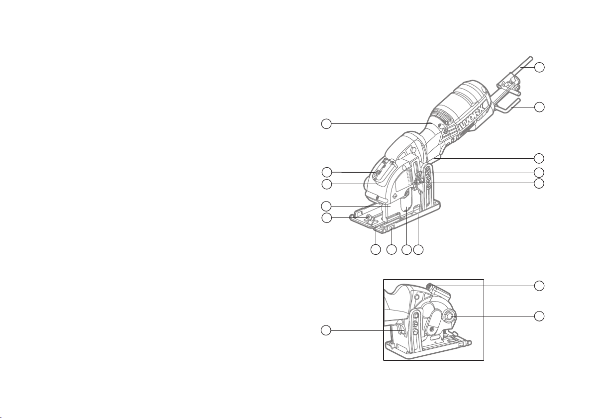
Component list
On/ Off Switch
1
Soft Grip Handle
2
Large L Spanner/ Hex KEY
3
Small L Spanner/Hex KEY
4
Laser On -Off Switch
5
Lock Off Switch
6
Dust Extraction Outlet
7
Depth of Cut Adjustment And Lock Lever
8
Base Plate
9
Saw Blade
10
Parallel Guide Fixture
11
Blade Alignment Indicator
12
Parallel Guide Clamping Screw
13
Protective Blade Guard
14
Laser Guide
15
Battery Storage Cover
16
Spindle Clamping Screw ( See Fig. C )
17
Blade Clamping Washer (See Fig. C )
18
Parallel Guide (See Fig. D)
19
Vacuum Adapter ( See Fig. E)
20
21
22
23
Plastic Base Plate Cover (See Fig. F1)
Laser Batteries (Two) (See Fig. J3)
Depth of Cut Indicator
* Not all the accessories illustrated or described are included in
standard delivery.
Page 8
8
Technical data
Vibration Information
Type WU420 (4-designation of machinery, representative of Saw)
•
Voltage 230-240V~50Hz
•
Power input 400W
•
No load speed 3500/min
•
Blade size Ø85mm X 15mm
•
Max cutting depth 27mm
•
Laser battery model no LR44 1.5V
•
Protection class /II
•
Machine weight 1.5kg
Noise and vibration data
A weighted sound pressure LPA: 80dB(A)
•
KPA 3dB(A)
•
A weighted sound power LWA: 91dB(A)
•
KWA 3dB(A)
•
Wear ear protection when sound pressure is over 80dB(A)
•
Vibration total values (triax vector sum) determined according to
•
EN 60745:
Typical weighted
•
vibration
Warning: The vibration emission value during actual use of the
power tool can differ from the declared value depending on the ways
in which the tool is used dependant on the following examples and
other variations on how the tool is used:
How the tool is used and the materials being cut or drilled.
The tool being in good condition and well maintained
The use the correct accessory for the tool and ensuring it is sharp and
in good condition.
The tightness of the grip on the handles and if any anti vibration
accessories are used.
And the tool is being used as intended by its design and these
instructions.
This tool may cause hand-arm vibration syndrome if its use is not
adequately managed.
Warning: To be accurate, an estimation of exposure level in
the actual conditions of use should also take account of all parts of
the operating cycle such as the times when the tool is switched off
and when it is running idle but not actually doing the job. This may
significantly reduce the exposure level over the total working period.
Vibration emission value ah =4.24m/s
Uncertainty K = 1.5m/s²
2
Helping to minimise your vibration exposure risk.
Page 9

9
ALWAYS use sharp chisels, drills and blades
Maintain this tool in accordance with these instructions and keep well
lubricated (where appropriate)
If the tool is to be used regularly then invest in anti vibration
accessories.
Avoid using tools in temperatures of 10
Plan your work schedule to spread any high vibration tool use across a
number of days.
o
C or less
Accessories
•
TCT 24T Blade 1
•
Diamond disc 1
•
HSS 44T Blade 1
•
V base 1
•
Parallel Guide 1
•
Vacuum Adaptor 1
•
Plastic base plate cover 1
•
Hex key 2
We recommend that you purchase your accessories from the same
store that sold you the tool. Use good quality accessories marked
with a well-known brand name. Choose the type according to the
work you intend to undertake. Refer to the accessory packaging for
further details. Store personnel can assist you and offer advice.
Page 10

10
Operating instructions
Note: Before using the tool, read the instruction book carefully.
INTENDED USE :
The machine is intended for ripping and cross-cutting wood and other
materials in straight cutting lines, while resting firmly on the work
piece.
Assembly
1
INSTALL /CHANGE THE BLADE
WARNING:
• Before any work on the machine itself, unplug the saw.
• Wear protective gloves when mounting the saw blade.
Danger of injur y when touching the saw blade.
• Only use saw blades that correspond with the
characteristic data given in the operating instructions.
• Do not use grinding discs on this cutting tool under any
circumstances.
1) Insert the small “L” spanner(4 into the center bolt hole on the back
of the spindle assembly.( See Fig. A)
2) Place the large “L” spanner (3) into the blade spindle clamping
screw (17) , while keeping the small “L” spanner in the center bolt
hole on the back of the spindle assembly. Turn the large “L” spanner
clockwise while holding the small “L” spanner stationary. Remove
the screw (17) and the blade clamping washer (18). After the washer
is removed, slide the blade off the spindle and through the blade slot
at the bottom of the saw. (See Fig. B1,B2)
Page 11

11
3) Clean the replacement saw blade and all the clamping parts to be
assembled. Slide the saw blade up through the slot and fit it onto
the inner spindle. Assemble the blade clamping washer (18) and the
spindle clamping screw (17). Use the two spanners to tighten the
spindle clamping screw thoroughly.(See Fig. C)
The steps involved in changing the blade are the same as the steps
used when installing the blade.
NOTE: Remove both spanners after the saw blade is tightly
attached.
WARNING: When mounting, ensure that the cutting direction of
theeth (direction of arrow on saw blade) and the direction-of-rotation
arrow above the blade guard match.
NOTE: Never use a blade that is too thick to allow the blade clamping
washer to engage with the flat side of the spindle.
The table below gives you advice on how to choose correct
blade.
Blade type Cutting material
TCT 24T Wood and aluminum
HSS 44T Thin sheet steel and aluminum, PVC pipe, plastic .
Diamond Concrete, marble, tile , cement backerboard.
Recommended maximum material thickness
Wood 27 mm
Aluminum 3 mm
PVC pipe (radius ) 13 mm
Tile 8 mm
Sheet steel 0. 91mm(20 gauge )
Page 12

12
PARALLEL GUIDE (See Fig. D)
2
The parallel guide is used for making cuts parallel to a work-piece
edge at a chosen distance and can be used from either side of the
base plate (9). Slide the parallel guide (19) arm through the fixture(11)
to achieve the required cutting distance and tighten the clamping
screw (13) with the small “L” spanner to lock into position. Do not
over tighten. The parallel guide enables exact cuts along a workpiece
edge and can also be used for cutting parallel strips.
NOTE: Since the parallel guide clamping screw is spring-loaded, the
operator should take care when unscrewing it completely as to avoid
losing the screw and spring.
SAWDUST REMOVAL (See Fig. E)
3
Your saw includes a vacuum adapter (20) that attaches to the dust
extraction outlet (7) on the saw. This adapter port can be attached to
a vacuum cleaner (sold separately). The use of the vacuum is strongly
recommended as it keeps the work area clean, dramatically increases
cut visibility and reduces airborne dust. It also keeps dust out of the
working elements of the guard.
NOTE:If using the saw without a vacuum attached, in some
circumstances after lengthy operation, dust can accumulate at the
rear of the base and prevent it from reaching full depth. You can
prevent this by occasionally shaking the dust out.
PLASTIC BASE PLATE COVER (See Fig. F1, F2)
4
Your saw includes a plastic base plate cover ( 21). Attach it to your
saw’s base when you are cutting work pieces that have delicate
surfaces (finishes) such as vinyls, plastics, fiberglass, laminate
flooring and tiles that could easily be scratched by the steel base.
Page 13

13
Operation
1
TRIGGER SWITCH (See Fig. G)
The on/off switch is locked off to prevent accidental starting. In order
to turn the machine on, depress and hold the lock off switch (6),
then depress the on/off switch (1) and release the lock off switch.
Your switch is now on. To switch off, just release the on/off switch.
NOTE: When the machine is not in use, the lock off switch rests
against the blade guard in order to block the plunge function and
prevent the blade from being exposed unnecessarily.
2
SET THE BLADE DEPTH
NOTE:The correct choice of cutting depth can improve ease of
cutting and cut quality.
Always use the minimum cut depth that is required for your particular
cut, which should just cut through the material plus a small allowance
e.g. 3 mm.
Excessive cutting depth increases splintering in wood, chipping in tile
and causes severe chatter in sheet steel and aluminum (which can
quickly blunt the blade).
Maximum depth can be used when cutting internal cut-outs in wood
as this reduces the overcutting required.
1) Determine the desired depth according to the thickness of the
material plus a blade allowance of 1/8” (3 mm).
2) Unlock the depth of cut adjustment and lock lever (8 ). ( See Fig. H1)
3) Slide the depth of cut indicator to the desired depth of cut. Lock
down the depth of cut adjustment and lock lever (8). (See Fig. H2)
When plunge or pocket cutting into the middle (or interior) of the
work piece, through the narrow slot, you can easily see the cutting
mark you draw and the location where the blade will plunge into the
Page 14

14
J1
J2
16
J2
22
J1
J2
J3
J4
16
J2
J4
22
J1
J2
J3
J4
J5
J6
16
work piece, based on the blade depth that was selected.
Always practice in a scrap work piece to become familiar with this
cutting operation. The selected depth of cut is now set. When the
saw’s blade is manually lowered, the blade will be below the base at
the selected depth.
The laser is used as a cutting guide and should form a red line on
the material surface that is exactly aligned with the blade alignment
indicator (12).
Press down the laser on/off switch (5) to turn on the laser.
Press down the laser on/off switch again to turn off the laser. (See
Fig. I)
NOTE: Clean the laser generator periodically.
WARNING: Never stare directly into the laser beam and never
point the beam at anybody. The laser beam energy is extremely
harmful to human eyes.
WARNING: When not in use, always turn the laser off to save
the battery capacity.
3
TO REPLACE LASER BATTERIES (See Fig. J1-J6)
The saw comes with laser batteries well assembled. When battery
capacity runs out, replace batteries as follows:
Use 1.5V batteries model LR44, typical to calculators, cameras and
similar small electronics.
Move the battery storage cover (16) in the direction the arrow (on the
cover) points. Then lift the battery storage cover (See Fig. J1, J2).
You can see one end of a cord. To remove the batteries, just slowly
pull the end of the cord. The two batteries will be taken out along
with the cord ( See Fig. J3).
To fit new batteries, adjust the position of the cord and insert two
batteries in place. Make sure two batteries are pressed on the cord
(See Fig. J4, J5).
Page 15

15
J2
J4
J6
22
J1
J2
J3
J4
J5
J6
K
L
J2
J4
J6
L
22
J3
J4
J5
J6
K
L
M
N
Restore the cover ( See Fig. J6).
NOTE: Pay attention that “+/-” of the batteries are the same as the
illustration on the machine.
4
CUTTING GUIDE (See Fig. K)
The blade alignment indicator (12) in the front of the base plate is
used as a cutting guide. Always guide it along the cutting mark made
on the workpiece for accurate cutting.
NOTE: It is best to carry out a trial cut.
Function
MAKING CROSS CUTS AND RIP CUTS (See Fig. L, M)
1
WARNING: To avoid sudden kick-back, never start a stationary
blade while it is in contact with the work piece.
Always start the saw and allow it to reach full speed before
commencing to plunge.
The blade teeth are exposed during this operation so proceed with
extreme caution.
a) A LWAYS use your saw with your hands positioned correctly.
WARNING: Always maintain proper control of the saw to make
sawing safer and easier. Loss of control of the saw could cause an
accident resulting in possible serious injury.
b) When making cross or rip cuts, align your line of cut with the
center of the “V” (blade alignment indicator), located on the front of
the saw’s base (See Fig. L).
c) Since the thickness of blades vary, make a trial cut in scrap material
along your cut mark to determine how much, if any, you should offset
the blade from the cut mark to allow for the blade thickness to get an
accurate cut.
Page 16

16
J4
J6
L
N
MAKING RIP CUTS (See Fig. M)
Always use a guide when making long rip cuts with your saw. You
can use any suitable straight edge clamped to the work or the parallel
guide that is included with your saw.
POCKET CUTTING (SOFT MATERIALS ONLY) (See Fig. N)
2
This operation requires much skill with a saw and must only be
carried out by a qualified person.
Clearly mark the area to be cut. Set the depth of cut on the saw (See
Fig. H1). Tilt the saw over the marked area with the front edge of the
base plate resting on the work surface and the back edge lifted above
the work surface. The cutting guide should be aligned with the line
you have marked on your workpiece. With the saw still in the tilted
position, apply pressure to the base plate so that the saw blade is
fully exposed through the blade slot in the base plate (according to
the depth of cut you have set). Ensure the blade is not touching but
is close to the work surface. Hold the saw firmly while applying the
least amount of pressure as possible on base plate. To avoid kickback,
you should hold the tool firmly before switching on the saw. switch
the saw on, wait for it to reach full speed, and gently guide the blade
down into the material but maintain a pivoting force on the front edge
of the base. Watch your cutting line by carefully looking through the
front end of the blade slot.
DO NOT bind the blade in the cut; push the saw blade forward at a
rate where the blade is not laboring.
When the cut is complete, release the trigger safety release
and switch and let the blade come to a complete stop. DO NOT
REMOVE the saw and blade from the workpiece while the blade is
moving. This could damage your cut (kerf), cause kickback and loss
of control, resulting in injury.
Page 17

17
Working hints for your circular
saw
If your Versacut becomes too hot, please run your VersacutTM no
load for 2-3 minutes to cool the motor. Avoid prolonged usage under
strenuous cutting loads.
Protect saw blades against impact and shock. Excessive feed
significantly reduces the performance capability of the machine and
reduces the service life of the saw blade. Sawing performance and
cutting quality depend essentially on the condition and the tooth
count of the saw blade. Therefore, use only sharp saw blades that are
suited for the material to be worked.
Choice of blades: 24 teeth for general work, approx. 40 teeth for finer
cuts, more than 40 teeth for very fine cuts into delicate surfaces,
diamond for tile, cement board, etc.
Maintenance
Remove the plug from the socket before carrying out any
adjustment, servicing or maintenance.
Keep tools sharp and clean for better and safer performance. Follow
instructions for lubricating and changing accessories. Inspect tool
cords periodically and if damaged, have repaired by authorized
service facility. Your power tool requires no additional lubrication or
maintenance. There are no user serviceable parts in your power tool.
Never use water or chemical cleaners to clean your power tool. Wipe
clean with a dry cloth. Always store your power tool in a dry place.
Keep the motor ventilation slots clean. Keep all working controls free
of dust.
If the supply cord is damaged, it must be replaced by the
manufacturer, its service agent or similarly qualified persons in order
to avoid a hazard.
Periodically clear dust and chips from guard and base to ensure
proper performance.
Page 18

18
Troubleshooting
Environmental protection
Symptom Possible Causes Possible Solution
Tool will not start
when operating the
on/ off switch.
Cutting depth is less
than that is set.
Blade spins or slips
Blade will not cut a
straight line.
Blade kicks back
when beginning a cut
Power cord not
plugged in.
Power cord is
broken.
Carbon brush has
worn down
Sawdust
accumulated at
the rear of the
base.
Blade is not tightly
engaged with the
spindle.
Blade is dull.
Blade is not
mounted properly.
Saw is not being
guided properly.
Blade is not
spinning fast
enough
Check to make sure
power cord is connected
well into a working outlet.
Unplug the power
cord. Replace it using a
qualified maintenance
person.
Replace the carbon
brush using a qualified
maintenance person.
Shake out sawdust.
Consider connecting
a vacuum for dust
collection.
Remove the blade,
and reassembled it as
described in INSTALL /
CHANGE THE BLADE
section.
Mount a new, sharp
blade on the saw.
Check that blade is
properly mounted.
Use an edge guide.
Allow the saw blade to
reach full speed prior to
beginning a cut
Waste electrical products should not be disposed of with
household waste. Please recycle where facilities exist. Check
with your local authorities or retailer for recycling advice.
Page 19

19
Connect
Blue to N
(neutral)
Outer sleeve
firmly clamped
Cable grip
Brown L (live)
13 Amp fuse approved
to BS1362
Plug replacement
(UK & Ireland only)
If you need to replace the fitted plug then follow the instructions
below.
IMPORTANT
The wires in the mains lead are colored in accordance with the
following code:
BLUE =NEUTR AL BROWN = LIVE
As the colors of the wires in the mains lead of this appliance may not
correspond with the colored markings identifying the terminals in
your plug, proceed as follows. The wire which is colored blue must
be connected to the terminal which is marked with N. The wire which
is colored brown must be connected to the terminal which is marked
with L.
NOTE: If a moulded plug is fitted and has to be removed take great
care in disposing of the plug and severed cable, it must be destroyed
to prevent engaging into a socket.
WARNING!
Never connect live
or neutral wires to
the earth terminal
of the plug. Only
fit an approved
13ABS1363/A plug
and the correct
rated fuse.
Page 20

EC DECLARATION OF
CONFORMITY
We,
Positec Power Tools (Europe) Ltd, PO Box 152,
Leeds, LS10 9DS, UK
Declare that the product,
Description WORX Mini circular saw
Typ e WU420 (4-designation of machinery, representative of Saw)
Function Cutting various materials with a rotating toothed blade
Complies with the following Directives,
•
EC Machiner y Directive 2006/42/EC
•
EC Electromagnetic Compatibility Directive 2004/108/EC
Standards conform to
EN 55014-1 EN 55014-2 EN 61000-3-2
EN 61000-3-3 EN 60745-1 EN 60745-2-5
The person authorized to compile the technical file,
Name Russell Nicholson
Address Positec Power Tools (Europe)Ltd, PO Box 152, Leeds,
LS10 9DS, UK
2012/08/08
Leo Yue
POSITEC Qualit y Manager
20
Page 21

Page 22

Page 23

Page 24

2PSC15APK11002A0
Copyright © 2012, Positec. All Rights Reserved.
 Loading...