

IMPACT DRILL
Impact drill
Schlagbohrer
Perceuse à percussion
Trapano a percussione
Taladro percutor
Berbequim de percurssão
Klopboormachine
•
•
•
•
•
•
•
Slagbor
Iskuporakone
Slagbor
Stöt borning
Darbeli matkap
Κρουστικό δράπανο
Дрель ударная
•
•
•
•
•
•
•
EN 04
D
11
F 19
I
26
ES
32
PT 39
NL
46
DK 53
FIN
60
NOR
67
SV
73
TR 79
GR
85
RU
92
WU302 WU302.1

3
2
1
6
4
7
9
5
8

4
1
2
3
4
5
6
7
8
9
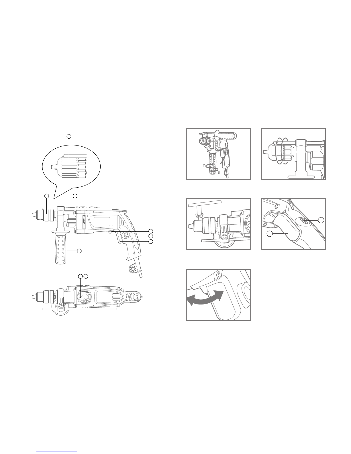
Component list
On/off switch with varible speed control
Switch lock-on button
Forward and reverse selector switch
Key chuck (WU302)
Auxiliary handle
Depth stop
Hammer or drill selector switch
Keyless chuck (WU302.1)
Lock button for hammer or drill selector switch
Not all the accessories illustrated or described are included in
standard delivery.
Technical data
Rated voltage 220V-240V~50Hz/60Hz
Rated input power 900W
Rated no load speed 0-2600/min
Rated impact rate 0-41600bpm
Protection class /II
Chuck capacity max. 13mm
Drilling capacity max.
masonry 20mm
steel 13mm
wood 35mm
Machine weight 2.2Kg
Noise and vibration data
A weighted sound pressure 94dB (A)
A weighted sound power 105dB (A)
Wear ear protection when sound pressure is over 85dB (A)
Impact drilling into concrete 15.73m/s2 K=1.5m/s
2
Drilling into metal 2.49m/s2 K=1.5m/s
2
Accessories
Auxiliary handle 1pc
Depth stop 1pc
Chuck key (WU302) 1pc
We recommend that you purchase your accessories from the same
store that sold you the tool. Use good quality accessories marked
with a well-known brand name. Choose the type according to the
work you intend to undertake. Refer to the accessory packaging for
further details. Store personnel can assist you and offer advice.
•
•
•
•
•
•
•
•
•
•
•
•
•
•
•
•
5
1
2
3
4
5
6
7
8
9
10
11
Additional safety points for your
drill
Remove the plug from the socket before carrying out any adjustment,
servicing or maintenance.
Fully unwind cable drum extensions to avoid potential overheating.
When an extension cable is required you must ensure it has the
correct ampere rating for your power tool and that it is in a safe
electrical condition.
Ensure your mains supply voltage is the same as your tool rating plate
voltage.
Your tool is double insulated for additional protection against a
possible electrical insulation failure within the tool.
Always check walls and ceilings to avoid hidden power cables and
pipes.
After long working periods, external metal parts and accessories
could be hot.
Wear eye protection when operating this tool.
Wear ear protectors with impact drills. Exposure to noise can
cause hearing loss.
Use auxiliary handles supplied with the tool. Loss of control can
cause personal injury.
Hold tool by insulated gripping surfaces when performing an
operation where the cutting tool may contact hidden wiring.
Contact with a ‘live’ wire will also make exposed metal parts of the
tool‘live’and shock the operator.
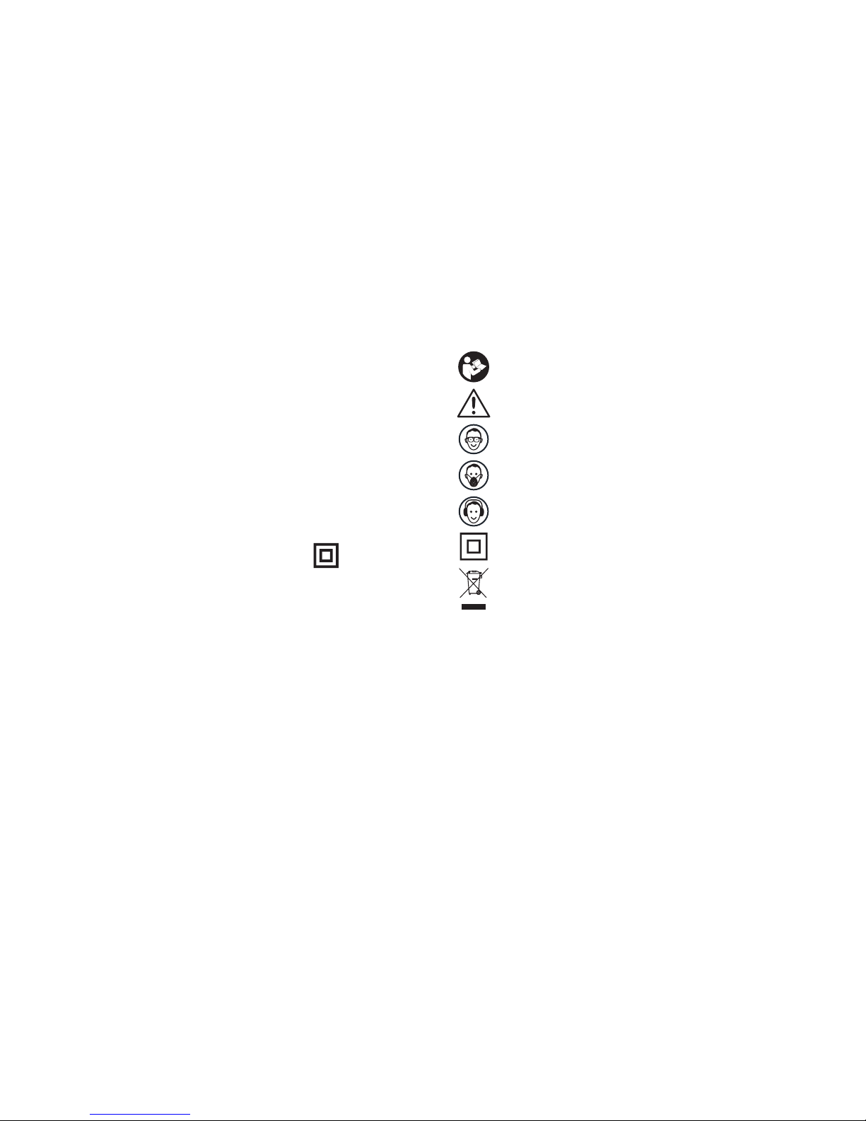
Symbols
Read the manual
Warning
Wear safety goggles
Wear dust mask
Wear ear protection
Double insulated
WEEE marking

6
1
Functional description
Note: Before using the tool, read the instruction book carefully.
INTENDED USE
The machine is intended for impact drilling in brick, concrete and
stone as well as for drilling in wood, metal and plastic. Machines
with electronic control and right/left rotation are also suitable for
screwdriving and thread-cutting.
Assembly
AUXILIARY HANDLE
a) Adjusting the auxiliary handle(See Fig A)
Slide the handle onto the drill and rotate to the desired working
position. To clamp the auxiliary handle rotates the handgrip
clockwise. To loosen the auxiliary handle rotate the hand grip anticlockwise.
Warning: Always use the auxiliary handle.
b) Adjusting the drilling depth
Fit the drill bit or driver bit into the chuck. Loosen the depth stop by
rotating the handle grip anti-clockwise. Slide the depth stop until the
distance between the depth stop end and the drill/driver bit end is
equal to the depth of hole/screw you wish to make. Then clamp the
depth stop by rotating the handle clockwise.
INSERTING THE TOOL(See Fig B)
Warning: Before any work on the machine itself, pull the
mains plug.
Keyless chuck (8) (WU302.1)
To open the chuck jaws rotate the front section of the chuck while
holding the rear section. Insert the drill bit between the chuck jaws
and rotate the front section in the opposite direction while holding the
rear section. Ensure that the drill bit is in the center of the chuck jaws.
Finally, firmly rotate the two separate chuck sections in opposite
directions. Your drill bit is now locked in the chuck. (See Fig B.1)
Key chuck (4) (WU302)
Insert tool and tighten equally in all 3 bores with chuck key. (See Fig
B.2)
Operation
SWITCHING ON AND OFF(See Fig C)
To start the machine, press the On/Off switch (1) and keep it
depressed.
To lock the pressed On/Off switch(1), press the switch lock -on
button (2) and then release it.
2
1

7
To switch off the machine, release the On/Off switch (1) or when it
is locked with the switch lock-on button (2), briefly press the On/Off
switch (1) and then release it.
VARIABLE SPEED CONTROL
The speed of the drill varies with the amount of pressure applied to
the on/off switch (1), i.e. more pressure for higher speed.
FORWARD AND REVERSE ROTATION CONTROL (See Fig D)
The forward and reverse selector switch (3) is used to reverse the
rotational direction of the machine. However, this is not possible with
the On/Off switch (1) actuated.
Forward rotation: For drilling and screw driving use forward rotation
marked “ ” (lever is moved to the left).
Reverse rotation: Only use reverse rotation marked “ ” (lever is
moved to the right) to remove screws or release a jammed drill bit.
Warning: Never change the direction of rotation when the
tool is rotating, wait until it has stopped.
SETTING THE OPERATING MODE
Drilling and Screwdriving
Press the lock button (9) and set the hammer or drill selector switch
(7) to the “Drilling” symbol.
Impact Drilling
Press the lock button (9) and set the hammer or drill selector switch
2
3
4
(7) to the “hammer” symbol.
The hammer or drill selector switch (7) engages noticeably and can
also be actuated with the machine running.

8
Working hints
If your power tool becomes too hot, set the speed to maximum and
run it with no load for 2-3 minutes to cool the motor.
Tungsten carbide drill bits should always be used for concrete and
masonry.
When drilling in metal, only use HSS drill bits in good condition.
Always use a magnetic bit holder when using short screwdriver bits.
When drilling steel where possible use a pilot hole before drilling a
large diameter hole.
Maintenance
Remove the plug from the socket before carrying out any
adjustment, servicing or maintenance.
Your power tool requires no additional lubrication or maintenance.
There are no user serviceable parts in your power tool. Never use
water or chemical cleaners to clean your power tool. Wipe clean with
a dry cloth. Always store your power tool in a dry place. Keep the
motor ventilation slots clean. Keep all working controls free of dust.
Occasionally you may see sparks through the ventilation slots. This is
normal and will not damage your power tool.
If the supply cord is damaged, it must be replaced by the manufacturer
,
its service agent or similarly qualified persons in order to avoid a hazard.
Environmental protection
Waste electrical products should not be disposed of with
household waste. Please recycle where facilities exist. Check
with your local authorities or retailer for recycling advice.
1
2
3
4
5
9
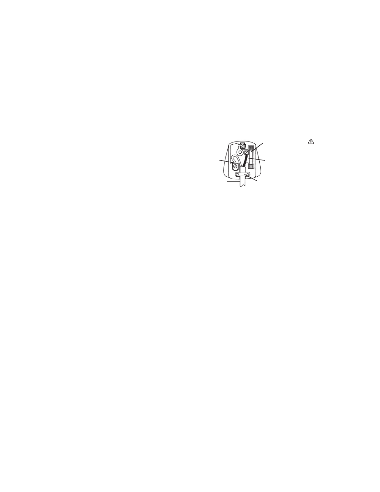
Plug replacement
(UK & Ireland only
)
If you need to replace the fitted plug then follow the instructions
below.
IMPORTANT
The wires in the mains lead are colored in accordance with the
following code:
BLUE =NEUTRAL BROWN = LIVE
As the colors of the wires in the mains lead of this appliance may not
correspond with the colored markings identifying the terminals in
your plug, proceed as follows. The wire which is colored blue must
be connected to the terminal which is marked with N. The wire which
is colored brown must be connected to the terminal which is marked
with L.
Note: If a moulded plug is fitted and has to be removed take great
care in disposing of the plug and severed cable, it must be destroyed
to prevent engaging into a socket.
Connec t
Blue to N
(neut ral)
Outer slee ve
firml y cla mped
Cable grip
Brown L (l ive)
13
Amp fuse approved
to B S1362
WARNING!
Never connect live
or neutral wires to
the earth terminal
of the plug. Only
fit an approved
13ABS1363/A plug
and the correct
rated fuse.

10
Declaration of conformity
We,
POSITEC Germany GmbH
Neuer Höltigbaum 6
22143 Hamburg
Declare that the product,
Description WORX Impact drill
Type WU302 WU302.1
Complies with the following Directives,
EC Machinery Directive 98/37/EC
EC Low Voltage Directive 2006/95/EC
EC Electromagnetic Compatibility Directive 2004/108/EC
Standards conform to
EN 55014-1 EN 55014-2 EN 61000-3-2
EN 61000-3-3 EN 60745-1 EN 60745-2-1
2006/01/01
Jacky Zhou
POSITEC Quality Manager
•
•
•

11
1
2
3
4
5
6
7
8
9
Bedienteile
Ein-Aus-Schalter mit Drehzahlregelung
Verriegelung für Dauerlauf
Schalthebel für Links-Rechts-Lauf
Zahnkranzbohrfutter nur (WU302)
Zusatz-Handgriff
Tiefenanschlag
Umschalter Bohren-Schlagbohren
Schnellspannbohrfutter nur (WU302.1)
Sperrknopf am Umschalter Bohren-Schlagbohren
Abgebildetes oder beschriebenes Zubehör gehört teilweise nicht
zum Lieferumfang.
Technische daten
Spannung 220V-240V~50Hz/60Hz
Nennaufnahmeleistung 900W
Leerlaufdrehzahl 0-2600/min
Nennschlagzahl 0-41600bpm
Schutzklasse /II(Schutzisoliert)
Max. Spannweite des Bohrfutters 13mm
Max. Bohrleistung
Mauerwerk 20mm
Stahl 13mm
Holz 35mm
Gewicht 2.2Kg
•
•
•
•
•
•
•
•
Lärmpegel und vibrationen
Gewichteter Schalldruck 94dB (A)
Gewichtete Schallleistung 105dB (A)
Tragen Sie bei einem Schalldruck über 85 dB (A) einen Gehörschutz
Schlagbohren in Beton 15.73m/s2 K=1.5m/s
2
Bohren in Metall 2.49m/s2 K=1.5m/s
2
Lieferumfang
Handgriff vorne 1
Tiefenanschlag 1
Bohrfutterschlüssel nur WU302 1
•
•
•
•
•
•
•
•

12
1
2
3
4
5
6
7
Allgemeine
Sicherheitsanweisungen-Siehe
Beiblatt
Wir danken Ihnen für den Kauf dieses Gerätes und hoffen, daß es
Ihren Anforderungen entspricht.
Damit das Arbeiten ein voller Erfolg wird, bitten wir Sie, diese
Gebrauchsanweisung vor dem Benutzen sorgfältig durchzulesen.
Diese Bedienungsanleitung besteht aus 2 Teilen – Allgemeine
Sicherheitsanweisungen und spezielle Sicherheitshinweise.
Bewahren Sie alle Teile dieser Anleitung zum künftigen Gebrauch
sorgfältig auf, geben Sie das Gerät nur zusammen mit allen Teilen der
Anleitung weiter.
Anwendung:
Das Gerät ist für das Bohren von Holz, Metall und Kunststoffen sowie
für das Schlagbohren in Stein, Ziegelstein, Mauerwerk und Beton
vorgesehen.
Geräte mit elektronischer Regelung und Rechts-/Linkslauf sind auch
geeignet zum Schrauben und Gewindeschneiden.
Das Gerät ist nicht für den gerwerblichen Gebrauch vorgesehen.
Spezielle Sicheheitshinweise für
Schlagbohrmaschinen
Achtung! Der Gebrauch anderer als in dieser
Bedienungsanleitung empfohlener oder im Lieferumfang
enthaltener Zubehörteile oder Zusatzgeräte kann eine
Verletzungsgefahr bedeuten.
Bei der Benutzung von Schlagbohrmaschinen sind
Gehörschützer zu tragen. Die Einwirkung von Lärm kann
Gehörschäden hervorrufen.
Benutzen Sie stets den mit dem Gerät gelieferten
Zusatzhandgriff. Mangelnde Kontrolle über das Gerät kann zu
Verletzungen führen.
Elektrowerkzeuge nicht unbeaufsichtigt laufen lassen. Gerät
immer ausschalten und erst ablegen oder verlassen, wenn das Gerät
völlig zum Stillstand gekommen ist.
Schalten Sie das Gerät erst aus, bevor Sie das Gerät an Ihrem
Körper abwärts bewegen.
Bei langem Haar muss das Haar abgedeckt sein. Arbeiten Sie
nur mit eng anliegenden Kleidungsstücken.
Achtung beim Bohren in Wänden: Die Beschädigung von
Stromleitungen, Gasleitungen oder Wasserleitungen kann
gefährliche Situationen heraufbeschwören! Benutzen Sie geeignete
Detektoren oder fragen Sie einen Fachmann, um festzustellen, ob im
Arbeitsbereich verborgene Leitungen liegen.

13
8
9
10
11
12
13
14
15
16
Kontrollieren Sie immer, ob die Netzspannung mit der auf dem
Typenschild angegebenen Spannung übereinstimmt.
Sichern Sie das Werkstück. Nur ein mit Spannvorrichtungen oder
im Schraubstock festgehaltenes Werkstück ist sicher gehalten.
Besondere Vorsicht ist bei der Bearbeitung von Blech
notwendig.Halten Sie Blechstücke niemals mit der Hand - auch
nicht bei kleinen Bohrungen -, verwenden Sie zum Festhalten eine
geeignete Zange, Schraubzwingen oder ähnliches.
Verwendung von Verlängerungskabeln.
Benutzen Sie ausschließlich Verlängerungskabel, die für die
Maschinenleistung ausgelegt sind. Der Mindestaderquerschnitt
muss 1,5mm² betragen. Bei Verwendung einer Kabeltrommel muss
das Kabel immer vollständig abgerollt werden, um eine Überhitzung
zu vermeiden.
Vor Bohrer-oder Zubehör-Wechsel stets den Netzstecker
ziehen.
Bohrfutterschlüssel stets aus Bohrfutter entfernen. Lassen Sie
die Maschine keinesfalls mit steckendem Bohrfutterschlüssel
laufen. Verwahren Sie den Bohrfutterschlüssel stets in der dafür
vorgesehenen Halterung am Gerät, Nähe Eingang des Netzkabel.
Vor dem Umschalten der Drehrichtung stets den Stillstand der
Maschine abwarten.
Vorsicht, Bohrer können sehr heiss werden.
Bearbeiten Sie keinen Asbest oder asbesthaltige Materialien.
Beachten Sie, dass Staub von verschiedenen
Holzarten, vorbehandeltem Holz, Mauerwerk, Stein
17
usw. gesundheitsschädlich sein kann. Sorgen Sie für
Staubabsaugung und gute Durchlüftung
Wenn ein Ersatz von Stecker oder Anschlussleitung
erforderlich ist, dann ist dies von unserer Servicestelle
oder einer Elektrofachwerkstatt durchzuführen, um
Sicherheitsgefährdungen zu vermeiden.
Lassen Sie Reparaturen nur durch unsere Servicestelle oder
durch eine Fachwerkstatt mit Originalersatzteilen durchführen.
Damit wird sichergestellt, dass die Sicherheit des Gerätes erhalten
bleibt.
14
1
2
3
Inbetriebnahme
Hinweis: Lesen Sie die Bedienungsanleitung vor
Inbetriebnahme sorgfältig durch.
EIN-AUS-SCHALTER MIT DREHZAHLEINSTELLUNG (Fig. C)
Zum Einschalten/Anlauf des Werkzeugs drücken Sie auf den Schalter
(1). Zum Stoppen lassen Sie den Schalter wieder los.
Das Werkzeug hat eine Drehzahleinstellung. Die Drehzahl wird durch
Druck auf den Schalter eingestellt, je stärker der Druck, desto höher
die Drehzahl.
SCHALTERVERRIEGELUNG (Fig. C)
Drücken Sie den Ein/Aus-Schalter (1) und dann den
Verriegelungsschalter (2) gleichzeitig; lassen Sie den Ein/AusSchalter zuerst los und dann den Verriegelungsschalter. Ihr Werkzeug
ist jetzt auf Dauerbetrieb eingestellt. Zum Ausschalten drücken Sie
kurz den Ein/Aus-Schalter und lassen ihn wieder los.
SCHALTHEBEL FÜR LINKS-RECHTS-LAUF (Fig. D)
Warnung:Nur im Stillstand schalten. Drehrichtung vor
Arbeitsbeginn im Leerlauf prüfen.
Verwenden Sie zum Bohren und Eindrehen von Schrauben die
Einstellung Rechtslauf (Schalter nach links). Die Einstellung
Linkslauf (Schalter nach rechts) soll nur zum Ausdrehen von
Symbole
Lesen Sie die Bedienungsanleitung
Warnung
Warnhinweis
Augenschutz tragen
Staubschutzmaske tragen
Gehörschutz tragen
Schutzisolation
WEEE-Kennzeichnung

15
Schrauben, Gewindebohrern und ggf. von geklemmten grossen
Bohrern verwendet werden.
ZUSATZHANDGRIFF (Fig. A)
Setzen Sie den Zusatzhandgriff (5) auf die Bohrmaschine und drehen
Sie ihn in die gewünschte Position.
Zum Festziehen drehen Sie ihn im Uhrzeigersinn nach rechts.
Lösen gegen Uhrzeigersinn nach links.
Arbeiten Sie immer mit Zusatzhandgriff.
TIEFENANSCHLAG (Fig. A)
Lösen Sie den Handgriff durch drehen nach links gegen
Uhrzeigersinn und setzen Sie den Tiefenanschlag (6) ein. Verschieben
Sie den Tiefenanschlag, bis er der gewünschten Bohrtiefe entspricht.
Fixieren Sie den eingestellten Tiefenanschlag, indem Sie den Griff
nach rechts im Uhrzeigersinn festdrehen.
BOHRFUTTER
Warnung: Ziehen Sie den Netzstecker, ehe Sie Zubehörteile
installieren. Versuchen Sie nicht, Bohrer (oder andere Werkzeuge)
einzuspannen, indem Sie den vorderen Teil des Bohrfutters festhalten
und das Werkzeug anlaufen lassen. Das Bohrfutter kann beschädigt
werden, Sie können sich verletzen.
6.1 SCHNELLSPANNBOHRFUTTER NUR WU302.1 (FIG. B1)
Zum Öffnen drehen Sie den vorderen Teil des Bohrfutters (8),
4
5
6
während Sie gleichzeitig den hinteren Teil festhalten. Stecken Sie den
Bohrer in das Bohrfutter, halten Sie den hinteren Teil des Bohrfutters
fest und drehen Sie den vorderen Teil in entgegengesetzter
Richtung. Achten Sie darauf, dass der Bohrer in der Mitte des
Bohrfutters sitzt. Zuletzt drehen Sie beide Teile des Bohrfutters
fest in entgegengesetzten Richtungen. Der Bohrer sitzt nun fest im
Bohrfutter.
6.2 ZAHNKRANZBOHRFUTTER NUR WU302 (Fig. B2)
Achten Sie darauf, dass der Bohrer im Zentrum des Bohrfutters sitzt.
Ziehen Sie zuerst das Zahnkranzbohrfutter (4) mit der Hand fest.
Ziehen Sie dann das Zahnkranzbohrfutter mit dem
Bohrfutterschlüssel fest (im Uhrzeigersinn nach rechts).
Ziehen Sie das Bohrfutter an allen drei Bohrungen gleichmäßig fest,
nicht nur an einer Bohrung!
Warnung: Entfernen Sie den Bohrfutterschluessel unbedingt
nach getaner Arbeit. Verwahren Sie den Bohrfutterschlüssel stets
in der dafür vorgesehenen Halterung am Gerät, nähe Eingang des
Netzkabels.
UMSCHALTER BOHREN-SCHLAGBOHREN
Der Umschalter (7) ist mit einem Sperrknopf (9) versehen, damit sich
die Einstellung beim Arbeiten nicht unbeabsichtigt ändert.
Wählen Sie zum Arbeiten in Mauerwerk, Stein und Beton die
Einstellung Schlagbohren.
Wählen Sie zum Bohren in Metall, Holz, Kunststoff und zum
7

16
Eindrehen von Schrauben die Einstellung Bohren.
Hinweis: Beim Bohren in Fliesen mit Betonbohrer beginnen Sie
mit der Einstellung Bohren. Wenn der Betonbohrer tief genug in die
Fliese eingedrungen ist, schalten Sie auf Schlagbohren um.
Arbeitshinweise für ihre
schlagbohrmaschine
Wenn die Schlagbohrmaschine zu heiß wird, lassen Sie sie 2 - 3
Minuten im Leerlauf laufen, um den Motor abzukühlen.
Verwenden Sie für das Bohren in Metall ausschließlich HSS-, HSSEBohrer in einwandfreiem Zustand.
Verwenden Sie beim Einsatz von kurzen Schraubeinsätzen einen
Magnethalter.
Große Bohrungen in Metall entsprechend vorbohren (etwa 1/3 – 1/2
Bohrdurchmesser).
Wartung
Ihr Werkzeug benötigt keine zusätzliche Schmierung oder Wartung.
Es enthält keine Teile, die Sie warten müssen.
Reinigen Sie Ihr Werkzeug niemals mit Wasser, Öl, Benzin, Alkohol,
Farbverdünnern oder sonstigen chemischen Reinigungsmitteln.
Wischen Sie es mit einem trockenen Tuch sauber.
Lagern Sie Ihr Werkzeug immer an einem trockenen Platz.
Halten Sie die Lüftungsschlitze sauber, entfernen Sie Staub mit
einem Pinsel.
Gelegentlich sind durch die Lüftungsschlitze hindurch Funken zu
sehen. Dies ist normal und wird Ihr Werkzeug nicht beschädigen.
1

17
Technische Änderungen
Text, Bild und Daten entsprechen dem technischen Stand der Zeit
zum Drucktermin. Änderungen im Sinne der Weiterentwicklung
unserer Produkte sind vorbehalten.
Umweltschutz
Schadhafte und/oder entsorgte elektrische oder elektronische
Geräte müssen an den dafür vorgesehenen Recycling-Stellen
abgegeben werden.
Wir möchten Sie daher bitten, uns mit Ihrem aktiven Beitrag beim
Umweltschutz zu unterstützen und dieses Gerät bei den Wertstoff-/
Recycling-Sammelstellen abzugeben.
Bitte erkundigen Sie sich bei der örtlichen Behörde oder beim
Vertragshändler über Müllsammlung und -Entsorgung.

18
Konformitätserklärung
Wir,
POSITEC Germany GmbH
Neuer Höltigbaum 6
22143 Hamburg
Erklären hiermit, dass unser Produkt
Beschreibung WORX Schlagbohrer
Typ WU302 WU302.1
Den Bestimmungen der folgenden Richtlinien entspricht:
EC Maschinenrichtlinie 98/37/EC
EC Niederspannungsrichtlinie 2006/95/EC
EC EMV-Richtlinie 2004/108/EC
Normen:
EN 55014-1 EN 55014-2 EN 61000-3-2
EN 61000-3-3 EN 60745-1 EN 60745-2-1
2006/01/01
Jacky Zhou
POSITEC Qualitätsleiter
•
•
•

19
1
2
3
4
5
6
7
8
9
Liste des composants
Commutateur on/off (marche/arret) avec controle a vitesse variable
Interrupteur avec dispositif de verrouillage
Commande de rotation avant et inversee
Mandrin à clé de (WU302)
Poignee laterale
Butee de profondeur ajustable
Commande de marteau ou de perceuse
Mandrin auto-serrant (WU302.1)
Bouton de verrouillage pour le sélecteur marteau ou perceuse
Les accessoires reproduits ou décrits ne sont pas tous compris dans
les fournitures.
Caracteristiques techniques
Tension nominale-fréquence 220V-240V~50Hz/60Hz
Puissance 900W
Vitesse à vide 0-2600/min
Cadence de frappe nominale 0-41600bpm
Double isolation /II
Capacité max. du mandrin. 13mm
Capacité max de perçage
béton 20mm
acier 13mm
bois 35mm
Poids de la machine 2.2Kg
•
•
•
•
•
•
•
•
Donnees sur le bruit et les
vibrations
Niveau de pression acoustique 94dB (A)
Niveau de puissance acoustique 105dB (A)
Porter des protections auditives lorsque la pression sonore est
supérieure à 85dB (A)
Perçage par percussion dans le béton 15.73m/s2 K=1.5m/s
2
Perçage dans le métal 2.49m/s2 K=1.5m/s
2
Accessoires
Poignée auxiliaire 1
Butée de profondeur 1
Clef de mandrin (WU302) 1
Nous recommandons d’acheter tous les accessoires dans le magasin
où l’outil a été acheté. Utilisez des accessoires de bonne qualité et de
marque.
Choisissez les meules adaptées au travail à réaliser. Reportez vous
à l’emballage pour de plus amples informations. Le personnel du
magasin peut apporter aide et conseils.
•
•
•
•
•
•
•
•

20
1
2
3
4
5
6
7
8
9
10
11
Mesures de securite
supplementaires pour la perceuse
Débrancher la prise avant d’effectuer des réglages, des réparations
ou d’entretenir l’outil.
Dérouler entièrement le câble d’extension afin d’éviter toute
surchauffe éventuelle.
Lorsqu’une rallonge est nécessaire, s’assurer qu’elle a le bon
ampérage pour votre outil et qu’elle est en bon état.
S’assurer que le voltage de votre source d’alimentation est le même
que celui de votre outil.
Votre outil possède une double isolation pour une meilleure
protection contre les éventuelles défaillances d’isolation à l’intérieur
de votre outil.
Toujours vérifier les murs et les plafonds afin de voir s’il y a des
câbles et tuyaux cachés.
A la suite de longues périodes de travail, les parties externes en
métal et accessoires pourraient être chauds.
Porter toujours des lunettes de protection.
Veuillez porter un casque antibruit lorsque vous utilisez une
perceuse à percussion. L’exposition au bruit peut causer la perte de
l’audition.
Veuillez utiliser les poignées auxiliaires fournies avec l’outil. La
perte de contrôle peut engendrer des blessures.
Tenir l’outil par les surfaces antidérapantes et isolées lorsque
l’outil de coupe risque d’entrer en contact avec des câbles
cachés. L’entrée en contact d’un câble sous tension rendra les
parties en métal de l’outil également sous tension et l’utilisateur
pourrait subir une décharge électrique.

21
Symboles
Lire le manuel
Avertissement
Porter une protection pour les yeux
Porter un masque contre la poussière
Porter une protection pour les oreilles
Double isolation
Marquage DEEE
1
Description du fonctionnement
Remarque: Avant d’utiliser cet outil, lire attentivement les
instructions.
RESTRICTIONS D’UTILISATION
L’appareil est conçu pour les travaux de perçage à percussion dans la
brique, le béton et dans la pierre naturelle ainsi que pour le perçage
dans le bois, le métal, la céramique et les matières plastiques. Les
appareils avec réglage électronique et rotation à droite/à gauche sont
également appropriés pour le vissage et le filetage.
Montage
POIGNÉE AUXILIAIRE
a) Poignée auxiliaire(Voir Fig A)
Faire glisser la poignée sur la perceuse et la faire pivoter jusqu’à la
position désirée. Pour fixer la poignée latérale, faire tourner la poignée
dans le sens inverse des aiguilles d’une montre. Pour desserrer la
poignée latérale faire tourner la poignée dans le sens des aiguilles
d’une montre.
Avertissement: Toujours utiliser la poignée latérale.

22
b) Butee de profondeur ajustable
Insérez le foret ou la mèche sur le mandrin. Desserrez le buteur
de profondeur en tournant la poignée dans le sens des aiguilles
d’une montre. Faites glisser l’arrêt de profondeur jusqu’à ce que la
distance entre l’arrêt de profondeur et le foret/mèche soient égaux
à la profondeur du trou/tournevis que vous désirez faire ou insérer.
Ensuite serrez le buteur de profondeur en tournant la poignée dans le
sens inverse des aiguilles d’une montre.
MISE EN PLACE DE L’OUTIL (Voir Fig B)
Avertissement: Before any work on the machine itself, pull
the mains plug.
Mandrin auto-serrant (8) (WU302.1)
Pour ouvrir les mors, tournez la section avant du mandrin pendant
que vous tenez la section arrière. Insérer le foret de la perceuse
entre les mors et tournez la section avant dans la direction opposée
pendant que vous tenez la section arrière. Assurez-vous que le foret
de la perceuse est dans le centre des mors du mandrin. Finalement,
tournez fermement les deux sections séparées du mandrin dans des
directions opposées. Votre foret de perceuse est maintenant bloqué
dans le mandrin.( Voir Fig B.1)
Mandrin à clé de (4) (WU302)
Insérez l’outil et serrez de manière égale des trois alésages avec la clé
(Voir Fig B.2)
2
Fonctionnement
MISE EN FONCTIONNEMENT/ARRÊT (Voir Fig C)
Pour mettre l’outil électroportatif en marche, appuyer sur
l’interrupteur Marche/Arrêt (1) et le maintenir appuyé.
Pour bloquer l’interrupteur Marche/Arrêt appuyé , appuyer sur le
bouton de blocage (2).
Afin d’arrêter l’appareil électroportatif, relacher l’interrupteur
Marche/Arrêt (1) ou, s’il est bloqué par le bouton de blocage (2),
appuyer brièvement sur l’interrupteur Marche/Arrêt (1), puis le
relacher.
COMMANDE A VITESSE VARIABLE
La vitesse de la perceuse dépend de la pression appliquée sur le
commutateur On/Off (1), c’est-à-dire appuyez plus fort pour une
grande vitesse.
COMMANDE DE ROTATION AVANT ET INVERSEE (Voir Fig D)
Avec le commutateur de sens de rotation (3) le sens de rotation de
l’outil électroportatif peut être inversé. Ceci n’est cependant pas
possible, quand l’interrupteur Marche/Arrêt( 1) est appuyé.
Rotation vers l’avant : Pour percer et visser, utiliser la rotation avant
indiquée par un “ “ (le levier est placé sur la gauche).
Rotation vers l’arrière : Utiliser seulement la rotation inversée
indiquée par un “ “ (le levier est placé sur la droite) pour retirer des
1
2
3

23
vis ou dégager une mèche bloquée (le levier est déplacé sur la droite)
Avertissement: Ne jamais changer le sens de rotation
lorsque l’outil tourne, attendre qu’il soit arrêté.
RÉGLER LE MODE DE SERVICE
Perçage et vissage
Appuyez sur le bouton de verrouillage (9) et réglez le sélecteur de
marteau ou de perceuse (7) sur le symbole “Perceuse”.
Perçage à percussion
Appuyez sur le bouton de verrouillage (9) et réglez le sélecteur de
marteau ou de perceuse (7) sur le symbole “marteau”.
Le commutateur (7) s’encliquette de manière perceptible et il peut
être actionné même pendant que l’appareil est en marche.
4
Conseil d’utilisation de la
perceuse
Si l’outil motorisé devient trop chaud, régler la vitesse sur le
maximum et le faire tourner à vide pendant 2-3 minutes pour refroidir
le moteur.
Les mèches en carbure de tungstène doivent toujours être utilisées
pour le béton et la maçonnerie.
Pour percer dans le métal, utiliser uniquement des mèches HSS en
bon état.
Utiliser toujours un porte-embout magnétique lors de l’utilisation de
mèches courtes.
Lorsque c’est possible, percer un trou de guidage avant de percer un
trou de gros diamètre.
Entretien
Retirer la fiche de la prise avant de procéder à un réglage, une
réparation ou un entretien.
L’outil motorisé ne requiert pas de graissage ou d’entretien
supplémentaire.
Il n’y a pas de pièces réparables par l’utilisateur dans cet outil. Ne
jamais utiliser d’eau ou de nettoyants chimiques pour nettoyer l’outil.
Nettoyer avec un chiffon sec. Toujours conserver l’outil motorisé dans
1
2
3
4
5

24
un endroit sec. Maintenir les fentes de ventilation du moteur propres.
Empêcher que les commandes de marche soient couvertes de
sciure. Il est normal que des étincelles soient visibles dans les fentes
de ventilation, cela n’endommagera pas l’outil motorisé.
Si l’alimentation est endommagée, elle doit être remplacée par le
fabricant, son agent de maintenance ou une personne qualifiée de
façon similaire, afin d’éviter tout danger.
Protection de l’environnement
Les déchets d’équipements électriques et électroniques ne
doivent pas être déposés avec les ordures ménagères. Ils
sont collectés pour être recyclés dans des centres spécialisés.
Consultez les autorités locales ou votre revendeur pour obtenir des
renseignements sur l’organisation de la collecte.

25
Declaration de conformite
Nous,
POSITEC Germany GmbH
Neuer Höltigbaum 6
22143 Hamburg
Déclarons ce produit
Description WORX Perceuse à percussion
Typ WU302 WU302.1
Est conforme aux directives suivantes:
Directive européenne Machine 98/37/EC
Directive européenne Basse Tension 2006/95/EC
Directive européenne sur la Comptabilité ElectroMagnétique
2004/108/EC
Et conforme aux normes:
EN 55014-1 EN 55014-2 EN 61000-3-2
EN 61000-3-3 EN 60745-1 EN 60745-2-1
2006/01/01
Jacky Zhou
Responsible qualité POSITEC
•
•
•

26
1
2
3
4
5
6
7
8
9
Elementi dell’apparecchio
Tasto on/off con velocità variabile
Pulsante di blocco
Controllo rotazione avanti ed indietro
Mandrino con chiave da (WU302)
Impugnatura ausiliaria
Asta di profondità
Controllo percussione o trapanatura
Mandrino autoserrante da (WU302.1)
Tasto bloccaggio selettore martello o trapano
Accessori illustrati o descritti non fanno necessariamente parte del
volume di consegna.
Dati tecnici
Tensione nominale 220V-240V~50Hz/60Hz
Potenza nominale 900W
Velocità nominale a vuoto 0-2600/min
Velocità impatto 0-41600bpm
Doppio isolamento /II
Capacità massima mandrino. 13mm
Capacità massima di foratura
muratura 20mm
acciaio 13mm
legno 35mm
Peso 2.2Kg
•
•
•
•
•
•
•
•
Dati sulla rumorosità e sulle
vibrazioni
Pressione acustica ponderata A 94dB (A)
Potenza acustica ponderata A 105dB (A)
Indossare protezione per le orecchie quando la pressione acustica è
superiore a 85dB(A)
Foratura a percussione su cemento 15.73m/s2 K=1.5m/s
2
Foratura su metallo 2.49m/s2 K=1.5m/s
2
Accessori
Impugnatura ausiliaria 1
Asta di profondità 1
Chiave per mandrino (WU302) 1
Si raccomanda di acquistare tutti gli accessori nello stesso negozio in
cui è stato acquistato l’attrezzo. Usare accessori di buona qualità e di
marca rinomata. Fare riferimento ai suggerimenti operativi di questo
manuale oppure alla confezione degli accessori per altri dettagli. Il
personale del negozio può aiutarvi e consigliarvi.
•
•
•
•
•
•
•
•
27
1
2
3
4
5
6
7
8
9
10
11
Norme di sicurezza supplementari
relative all’uso del trapano
Rimuovere la spina dalla presa di corrente prima di eseguire qualsiasi
regolazione, riparazione o manutenzione.
Estrarre completamente il cavo di prolunga dal suo alloggio per
evitare il surriscaldamento.
In caso di utilizzo di un cavo prolunga, verificare sempre il corretto
amperaggio rispetto all’elettroutensile e che sia in buone condizioni.
Accertarsi che la tensione di alimentazione di rete corrisponda a
quanto riportato sulla targhetta delle specifiche.
L’attrezzo ha un doppio isolamento per la protezione da possibili
guasti al suo interno.
Controllare sempre pareti e soffitti per evitare tubature e cavi nascosti.
Dopo periodi prolungati d’attività, le parti metalliche esterne e gli
accessori possono diventare caldi.
Indossare occhiali per la protezione degli occhi quando si usa questo
attrezzo.
Indossare protezioni per le orecchie con tutti i trapani a
percussione. L’esposizione al rumore può provocare la perdita dell’udito.
Usare le impugnature ausiliarie fornite in dotazione all’attrezzo.
La perdita di controllo può provocare lesioni personali.
Afferrare lo strumento per le apposite maniglie quando si
eseguono operazioni durante le quali l’attrezzo potrebbe
entrare in contatto con cavi nascosti. Il contatto con cavi elettrici
in tensione espone l’operatore al rischio di scosse elettriche.
Simboli
Leggere il manuale
Attenzione
Indossare protezione per gli occhi
Indossare mascherina antipolvere
Indossare protezione per le orecchie
Doppio isolamento
Marchio WEEE

28
1
Descrizione del funzionamento
Nota: Leggere scrupolosamente il manuale delle istruzioni prima
di usare l’attrezzo.
USO CONFORME ALLE NORME
La macchina è idonea per l’esecuzione di forature battenti in mattoni,
nel calcestruzzo e nel materiale minerale; essa è adatta anche
per forare ed avvitare nel legname, nel metallo, nella ceramica e
nelle materie plastiche. Macchine con regolazione elettronica e
funzionamento reversibile sono adatte anche per avvitare e per
tagliare filettature.
Montaggio
IMPUGNATURA AUSILIARIA
a) Impugnatura ausiliaria(si veda la figura A)
Inserire l’impugnatura facendola scorrere sull’attrezzo e ruotarla sulla
posizione operativa desiderata. Per fissare l’impugnatura ausiliaria,
ruotarla in senso orario. Per allentare l’impugnatura ausiliaria, ruotarla
in senso antiorario.
Attenzione: Usare sempre l’impugnatura ausiliaria.
b)
Asta di profondità regolabile
Inserire la punta o l’utensile nel mandrino. Allentare l’asta di profondità
ruotando l’impugnatura in senso antiorario. Far scorrere l’asta di
profondità finché la distanza tra l’asta e la punta/utensile è uguale alla
profondità del foro che si vuole trapanare/vite che si vuole insediare.
Infine bloccare l’asta di profondità ruotando l’impugnatura in senso
orario.
INTRODURRE L’UTENSILE (Si veda la Figura B)
Attenzione: Prima di qualunque intervento alla macchina,
estrarre la spina dalla presa di rete.
Mandrino autoserrante da (8) (WU302.1)
Per aprire le ganasce del mandrino ruotare la sezione frontale del
mandrino mentre si tiene ferma la sezione posteriore. Inserire la
punta tra le ganasce del mandrino e ruotare la sezione frontale
in direzione opposta mentre si tiene ferma la sezione posteriore.
Assicurarsi che la punta sia collocata al centro delle ganasce del
mandrino. Infine, ruotare con fermezza ed in direzione opposta le
due sezioni separate del mandrino. Adesso la punta è bloccata nel
mandrino.( si veda la figura B.1)
Mandrino con chiave da (4) (WU302)
Inserire l’utensile e serrare in modo uniforme le 3 ganasce utilizzando
l’apposita chiave. (si veda la figura B.2)
2

29
Istruzioni operative
AVVIO/ARRESTO (Si Veda la Figura C)
Per accendere l’elettroutensile premere l’interruttore di avvio/arresto
(1) e tenerlo premuto.
Per fissare in posizione l’interruttore di avvio/arresto premuto (1)
premere il tasto di bloccaggio (2).
Per spegnere l’elettroutensile rilasciare di nuovo l’interruttore di
avvio/arresto (1) oppure se è bloccato con il tasto di bloccaggio( 2),
premere brevemente l’interruttore di avvio/arresto (1) e rilasciarlo di
nuovo.
CONTROLLO VELOCITÀ VARIABILE
La velocità di rotazione del trapano varia in relazione alla pressione
esercitata sull’interruttore on/off (1), p.e. pressione maggiore per
aumentare la velocità di rotazione.
CONTROLLO ROTAZIONE AVANTI ED INDIETRO (Si Veda la
Figura D)
Con il commutatore del senso di rotazione( 3 )è possibile modificare il
senso di rotazione dell’elettroutensile.
Comunque, ciò non è possibile quando l’interruttore di avvio/arresto
(1) è premuto.
Rotazione in avanti: Per trapanare ed avvitare usare la rotazione
avanti contrassegnata da “ ” (la leva è spostata sulla sinistra).
1
2
3
Rotazione indietro: Usare la rotazione inversa, contrassegnata da
“ ” (la leva è spostata sulla destra), solamente per rimuovere le viti
o le punte del trapano bloccate.
Attenzione: Non cambiare mai la direzione di rotazione
quando l’attrezzo è in movimento; attendere finché si è
fermato.
REGOLAZIONE DEL MODO OPERATIVO
Foratura ed avvitatura
Agire sul pulsante (9) per la selezionare martello/trapano e
posizionarlo (7) sul simbolo “Foratura”.
Foratura battente
Agire sul pulsante (9) per la selezionare martello/trapano e
posizionarlo (7) sul simbolo “martello”.
Il selettore (7) si incastra in maniera percepibile può essere azionato
quando la macchina è in esercizio.
4

30
Consigli sul funzionamento del
trapano
Se l’attrezzo diventa troppo caldo, impostare la velocità al massimo e
farlo funzionare a vuoto per 2-3 minuti per raffreddare il motore.
Le punte di carburo di tungsteno devono essere usate sempre
quando si lavora su calcestruzzo e muratura.
Quando si trapana il metallo, usare solamente punte HSS in buone
condizioni.
Usare sempre un portainserti magnetico quando si usano punte
corte.
Dove possibile, usare fori pilota prima di trapanare buchi di diametro
maggiore.
Manutenzione
Rimuovere la spina dalla presa di corrente prima di eseguire
qualsiasi regolazione, riparazione o manutenzione.
L’attrezzo non richiede di lubrificazione o manutenzione aggiuntiva.
All’interno dell’attrezzo non ci sono parti riparabili da parte dell’utente.
Non usare mai acqua o detergenti chimici per pulire l’attrezzo. Pulire
con un panno asciutto. Immagazzinare sempre gli attrezzi elettrici in
luoghi asciutti. Tenere pulite le aperture di ventilazione del motore.
Tenere puliti dalla polvere tutti i controlli operativi. La formazione
di scintille all’interno delle aperture di ventilazione, è un fenomeno
normale che non crea danni all’attrezzo.
Se il cavo d’alimentazione è danneggiato, deve essere sostituito dal
produttore, il suo distributore o persona egualmente qualificata per
evitare pericoli.
Protezione ambientale
I prodotti elettrici obsoleti non devono essere smaltiti insieme
ai rifiuti urbani. Riciclare i prodotti laddove sono presenti gli
appositi centri. Mettersi in contatto con le autorità locali, o con
il rivenditore, per informazioni sul riciclaggio.
1
2
3
4
5
 Loading...