

Page 1

SAFETY AND OPERATING MANUAL
ORIGINAL INSTRUCTIONS
3 in 1: Trimmer / Edger / Mini mower
WG169E WG169E.2 WG169E.5 WG169E.9
Page 2

Page 3

PRODUCT SAFETY
GENERAL SAFETY
WARNINGS
WARNING: Read all safety
warnings and all instructions.
Failure to follow the warnings and instructions
may result in electric shock, fire and/or serious
injury.
Save all warnings and instructions for
future reference.
The appliance is only to be used with the
power supply unit provided with the appliance.
IMPORTANT
READ CAREFULLY BEFORE USE
KEEP FOR FUTURE REFERENCE
Safe operating practices
1. TRAINING
a) Read the instructions carefully. Be familiar
with the controls and the correct use of the
machine.
b) Never allow children, persons with reduced
physical, sensory or mental capabilities or
lack of experience and knowledge or people
unfamiliar with these instructions to use the
machine, local regulations may restrict the
age of the operator.
c) Keep in mind that the operator or user
is responsible for accidents or hazards
occurring to other people or their property.
2. PREPARATION
a) Before use, always visually inspect
the machine for damaged, missing or
misplaced guards or shields.
b) Never operate the machine while people,
especially children, or pets are nearby.
3. OPERATION
a) Wear eye protection, long trousers and
stout shoes at all times while operating the
machine.
b) Avoid using the machine in bad weather
conditions especially when there is a risk of
lightning.
c) Use the machine only in daylight or good
artificial light.
d) Never operate the machine with damaged
guards or shields or without guards or
shields in place.
e) Switch on the motor only when the hands
and feet are away from the cutting means.
f) Always disconnect the machine from the
power supply (e.g. remove the battery pack
from the machine)
1) Whenever the machine is left unattended;
2) Before clearing a blockage;
3) Before checking, cleaning or working on the
machine;
4) After striking a foreign object;
5) Whenever the machine starts vibrating
abnormally.
g) Take care against injury to feet and hands
from the cutting means.
h) Always ensure that the ventilation
openings are kept clear of debris.
i) Never fit metal cutting elements.
j) Always be sure of your footing on slopes.
k) Walk, never run.
l) Not overreach and keep the balance at all
times.
m) Not to touch moving hazardous parts
before removing the battery pack from the
machine and the moving hazardous parts
have come to a complete stop.
4. MAINTENANCE AND STORAGE
a) Disconnect the machine from the power
supply (e.g. remove the battery pack
from the machine) before carrying out
maintenance or cleaning work.
b) Use only the manufacturer’s recommended
replacement parts and accessories.
c) Inspect and maintain the machine regularly.
Have the machine repaired only by an
authorized repairer.
d) When not in use, store the machine out of
the reach of children.
SAFETY WARNINGS FOR
BATTERY PACK
a) Do not dismantle, open or shred cells
or battery pack.
b) Do not short-circuit a battery pack. Do
3
3 in 1: Trimmer / Edger / Mini mower
WG169E WG169E.2 WG169E.5 WG169E.9
Page 4

not store battery packs haphazardly
in a box or drawer where they may
short-circuit each other or be shortcircuited by conductive materials.
When battery pack is not in use, keep it
away from other metal objects, like paper
clips, coins, keys, nails, screws or other
small metal objects, that can make a
connection from one terminal to another.
Shorting the battery terminals together
may cause burns or a fire.
c) Do not expose battery pack to heat or
fire. Avoid storage in direct sunlight.
d) Do not subject battery pack to
mechanical shock.
e) In the event of battery leaking, do not
allow the liquid to come into contact
with the skin or eyes. If contact has
been made, wash the affected area
with copious amounts of water and
seek medical advice.
f) Seek medical advice immediately
if a cell or battery pack has been
swallowed.
g) Keep battery pack clean and dry.
4
h) Wipe the battery pack terminals with a
clean dry cloth if they become dirty.
i) Battery pack needs to be charged
before use. Always refer to this
instruction and use the correct
charging procedure.
j) Do not maintain battery pack on
charge when not in use.
k) After extended periods of storage,
it may be necessary to charge
and discharge the battery pack
several times to obtain maximum
performance.
l) Battery pack gives its best
performance when it is operated at
normal room temperature (20°C ±
5°C).
m) When disposing of battery packs,
keep battery packs of different
electrochemical systems separate
from each other.
n) Recharge only with the charger
specified by WORX. Do not use any
charger other than that specifically
provided for use with the equipment.
A charger that is suitable for one type of
battery pack may create a risk of fire when
used with another battery pack.
o) Do not use any battery pack which
is not designed for use with the
equipment.
p) Keep battery pack out of the reach of
children.
q) Retain the original product literature
for future reference.
r) Remove the battery from the
equipment when not in use.
s) Dispose of properly.
3 in 1: Trimmer / Edger / Mini mower
WG169E WG169E.2 WG169E.5 WG169E.9
Page 5
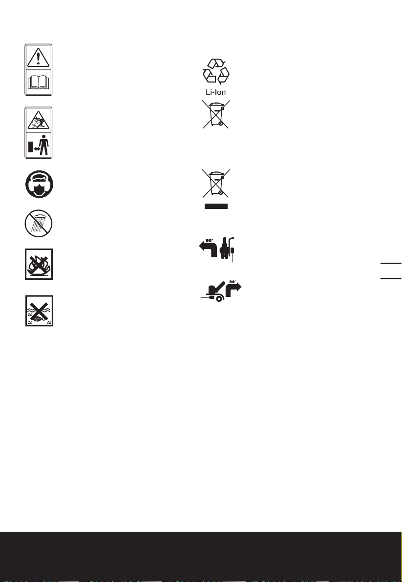
SYMBOLS
Read operator’s manual
Keep bystanders away
Wear eye and ear protection
Do not expose to rain
Li-Ion battery. This product has been
marked with a symbol relating to
‘separate collection’ for all battery
packs and battery pack. It will
then be recycled or dismantled in
order to reduce the impact on the
environment. Battery packs can be
hazardous for the environment and
for human health since they contain
hazardous substances.
Waste electrical products must not
be disposed of with household
waste. Please recycle where
facilities exist. Check with your local
authorities or retailer for recycling
advice.
Edging
Do not burn
Batteries may enter water cycle if
disposed improperly, which can
be hazardous for ecosystem. Do
not dispose of waste batteries as
unsorted municipal waste.
xINR18/65-y: Cylindrical lithium
Ion battery cells with max diameter
of 18mm and max height of
65mm; “x” represents a number
cells serial connected, blank if 1;
“-y” represents a number of cells
paralleled connected, blank if 1.
5
Trimming
3 in 1: Trimmer / Edger / Mini mower
WG169E WG169E.2 WG169E.5 WG169E.9
Page 6
7
9 10
8
11
15
6
14
4
3
2
1
12
13
6
5
3 in 1: Trimmer / Edger / Mini mower
WG169E WG169E.2 WG169E.5 WG169E.9
Page 7

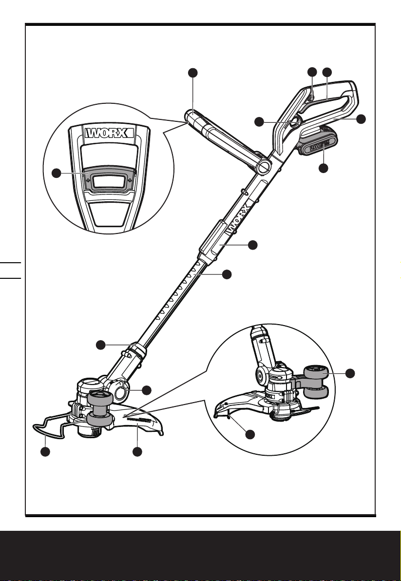
1. REAR HANDLE
2. BATTERY PACK
3. TELESCOPIC SHAFT
4. PIVOT HEAD LOCKING KNOB
5. SAFETY GUARD
6. FLOWER GUARD/EDGER GUIDE
7. AUXILIARY HANDLE
8. TELESCOPIC SHAFT ADJUSTMENT TRIGGER
9. LOCK OFF BUTTON
10. ON/OFF SWITCH
11. AUXILIARY HANDLE LOCKING LEVER
12. EDGER/TRIMMING SUPPORT WHEELS
13. LINE CUTTER
14. LOWER SHAFT COUPLING
15. UPPER SHAFT
16. MOTOR HOUSING OF TRIMMER HEAD (See Fig. H2)
17. LINE FEED BUTTON (See Fig. K1)
18 SPOOL CAP COVER (See Fig. K2)
19 CAP RELEASE LATCH (See Fig. K2)
20. SPOOL (See Fig. K2)
21. CUTTING HEAD (See Fig. K2)
22. EYELET (See Fig. K2)
7
Not all the accessories illustrated or described are included in standard delivery.
3 in 1: Trimmer / Edger / Mini mower
WG169E WG169E.2 WG169E.5 WG169E.9
Page 8

TECHNICAL DATA
Type WG169E WG169E.2 WG169E.5 WG169E.9 (1-designation of machinery,
representative of Grass Trimmer)
WG169E / WG169E.2 WG169E.5 WG169E.9
Voltage 20V
No load speed 7600/min
Cutting diameter 30cm
Line diameter 1.65mm
Charging time 5hr approx. 1hr approx. /
Machine weight 2.6kg 2.6kg 2.2kg
* Voltage measured without workload. Initial battery voltage reaches maximum of 20 volts.
Nominal voltage is 18 volts.
Max*
NOISE DATA
A weighted sound pressure LpA = 78dB(A)
3.0dB(A)
K
pA
A weighted sound power L
8
Wear ear protection
wA
= 94dB(A)
VIBRATION INFORMATION
Typical weighted vibration ah = 2.8m/s²
Uncertainty K = 1.5m/s²
The declared vibration total value may be used for comparing one tool with another, and may
also be used in a preliminary assessment of exposure.
WARNING! The vibration emission value during actual use of the power tool can differ
from the declared value depending on the ways in which the tool is used dependant on the
following examples and other variations on how the tool is used:
How the tool is used and the materials being cut or drilled.
The tool being in good condition and well maintained.
The use the correct accessory for the tool and ensuring it is sharp and in good condition.
The tightness of the grip on the handles and if any anti vibration accessories are used.
And the tool is being used as intended by its design and these instructions.
This tool may cause hand-arm vibration syndrome if its use is not adequately managed.
3 in 1: Trimmer / Edger / Mini mower
WG169E WG169E.2 WG169E.5 WG169E.9
Page 9

WARNING! To be accurate, an estimation of exposure level in the actual conditions of use
should also take account of all parts of the operating cycle such as the times when the tool
is switched off and when it is running idle but not actually doing the job. This may significantly
reduce the exposure level over the total working period.
Helping to minimize your vibration exposure risk.
ALWAYS use sharp chisels, drills and blades.
Maintain this tool in accordance with these instructions and keep well lubricated (where appropriate).
If the tool is to be used regularly then invest in anti vibration accessories.
Avoid using tools in temperatures of 10ºC or less.
Plan your work schedule to spread any high vibration tool use across a number of days.
ACCESSORIES
WG169E WG169E.2 WG169E.5 WG169E.9
Charger 1 (WA3760) 1 (WA3760) 1 (WA3860) /
Battery Pack 1 (WA3551.1) 2 (WA3551.1) 1 (WA3551.1) /
Edge/Trimming Support
Wheel
Spool 1 (WA0004) 1 (WA0004) 1 (WA0004) 1 (WA0004)
Safety Guard 1 1 1 1
We recommend that you purchase your accessories from the same store that sold you the tool.
Refer to the accessory packaging for further details. Store personnel can assist you and offer
advice.
1 1 1 1
9
3 in 1: Trimmer / Edger / Mini mower
WG169E WG169E.2 WG169E.5 WG169E.9
Page 10

ASSEMBLY
11
109
15
16
14
D
E
F1
C
G
H1
H2
F2
1. ASSEMBLY OF THE SAFETY GUARD
(See Fig. A)
Remove a screw from the Guard; attach the Safety
Guard to the trimmer head. Align the Guard so it slides
into the slots located on the trimmer head. Turn the tool
over and secure the Safety Guard onto the trimmer
head with the screw (a) provided.
a
A
b
2. ASSEMBLY OF THE EDGER/TRIMMING
SUPPORT WHEELS (See Fig. B1, B2, B3)
With the tool right side up, slide the Edger /Trimming
Support Wheels (12) assembly onto the metal plate
located on the side of the Cutting Head (See B1) or
underneath the Safety Guard(5) (See B2 B3). Make sure
the grooves of the Edger /Trimming Support Wheels
assembly locks onto the metal plate, you will hear it
click into place.
To remove the wheel assembly, press the release
button (b) on the wheels and pull the wheels outside.
10
OPERATION INSTRUCTIONS
B1
B2
B3
3 in 1: Trimmer / Edger / Mini mower
INTENDED USE
The machine is intended for the cutting of grass and
weeds under bushes, as well as on slopes and edges
that can not be reached with the lawn mower.
WARNING! The charger and Battery Pack are
specially designed to work together so do not
attempt to use any other devices. Never insert or allow
foreign metallic objects into your charger or Battery
Pack connections because of electrical failure and other
hazards that will occur.
1. BEFORE USING YOUR CORDLESS GRASS
TRIMMER
Your Battery Pack is UNCHARGED and it must be fully
charged once before it is used.
The battery charger supplied is matched to the Li-Ion
battery for use with this tool. Do not use another
battery charger.
2. CHARGING YOUR BATTERY PACK
The Li-Ion battery is protected against deep
discharging. When the battery is empty, the trimmer
will switch off by means of a protective circuit: The
trimmer head will stop rotating.
NOTE: In a warm environment or after heavy use, the
Battery Pack may become too hot to permit charging.
WG169E WG169E.2 WG169E.5 WG169E.9
Page 11

Allow time for the battery to cool down before
11
16
G
H1
H2
F2
recharging.
3. TO REMOVE OR INSTALL BATTERY PACK
(See Fig. C)
Depress the battery release button to remove Battery
Pack (2) from your trimmer. After recharging, insert the
Battery Pack onto trimmer’s battery bracket. A simple
push and slight pressure will be sufficient.
4. SAFETY ON/OFF SWITCH (See Fig. D)
The safety switch is locked off to prevent accidental
starting. Depress the Lock Off Button (9) then depress
the On/Off Switch (10) and release Lock Off Button. Your
trimmer is now on. To switch off, just release the on/off
switch.
WARNING! The cutting head continues to
rotate after the trimmer has been switched
off; wait until it has completely stopped then lay
down the tool.
5. ADJUSTMENT OF THE TELESCOPIC SHAFT
(See Fig. E)
Step one foot on the Safety Guard, then use one hand
to pull up the Telescopic Shaft Adjustment Trigger (8),
adjust the length of the Telescopic Shaft to the most
comfortable length. Release the Telescopic Shaft.
Adjustment Trigger to lock in position.
6. MAIN HANDLE ROTATION
(See Fig. F1, F2)
First, hold down the lower housing with your foot
and pull upward on the Upper Shaft (15). Then rotate
the Upper Shaft clockwise 90 degrees (See Fig. F1)
and release; the Shaft will be locked in position
automatically (See Fig. F2).
7. ADJUSTMENT OF AUXILIARY HANDLE
Pull up the Auxiliary Handle Locking Lever (11).
Hold the Locking Lever and rotate the Auxiliary Handle
to the most comfortable and balanced position (See
Fig. G)
Release the lever, your Auxiliary Handle has been
locked.
C
109
D
11
E
8. ADJUSTMENT OF THE TRIMMER HEAD ANGLE
TO THE SHAFT
(See Fig. H1, H2 & H3)
WARNING: Make Sure the Safety Switch is
Locked Off to Prevent Accidental Starting.
To adjust the Upper Shaft angle or convert the tool from
F1
15
14
3 in 1: Trimmer / Edger / Mini mower
WG169E WG169E.2 WG169E.5 WG169E.9
Page 12

12
F2
G
H1
trimming mode and edging mode, unlock the Pivot
Head Locking Knob by hand, and using adequate force,
pull the trimmer head into the desired position, then
lock the Pivot Head Locking Knob.
9. FLOWER GUARD/EDGER GUIDE
Pull the Flower Guard/Edger Guide out before
trimming, as shown in Fig. I1.
When edging, pull Flower Guard/Edger Guide out also,
and keep to a side (See Fig. I2).
Before trimming or edging make sure the flower guard
is locked firmly in position.
OPERATION
WARNING: Always wear the eye protection.
11
Never lean over the trimmer head. Rocks or
debris can ricochet or be thrown into eyes and face and
cause blindness or other serious injury. When operating
unit, check for the following:
Wear eye protection and heavy clothing. Hold front
handle with one hand and Auxiliary Handle with the
other hand. Keep unit below waist level. Work only from
your right to your left to ensure debris is thrown away
from you. Without bending over, keep line near and
parallel to the ground (perpendicular when edging) and
not crowded into material being cut.
WARNING: Make sure that line is fed out
before operation. Make sure motor is up to
full speed before trimming or edging.
WARNING: Only use 1.65mm diameter cutting
line. Other sizes of line will not feed properly and
will result in improper cutting head function or can
cause serious injury. Do not use other material such as
wire, string, rope, etc. Wire can break off during cutting
and become a dangerous projectile that can cause
serious injury.
EDGER/TRIMMING SUPPORT WHEELS
There are three optional positions for the Edger/
Trimming Support Wheels to attach when assisting in
Trimming and Edging.
POSITION 1: USING THE GUIDE WHEELS WHEN
TRIMMING IN A FORWARD OR REVERSE
DIRECTION (See Fig. J1)
16
H2
Position the Grass Trimmer in the trimming position.
Underneath the Safety Guard there is a metal plate
that the Edger/Trimming Support Wheels will attach to.
Slide the Support Wheels horizontally onto the metal
3 in 1: Trimmer / Edger / Mini mower
WG169E WG169E.2 WG169E.5 WG169E.9
Page 13

plate until they lock into position so both the wheels are
17
18
19
20
21
RIGHT
WRONG
22
K1
K2
K3
J2
L2
L3
L4
L1
facing in the forward direction (See Fig. B3). The wheels
should provide support when you are trimming in the
forward or reverse direction.
POSITION 2: USING THE GUIDE WHEELS WHEN
TRIMMING SIDE TO SIDE
Position the Grass Trimmer in the trimming position.
Underneath the Safety Guard there is a metal plate that
the Edger/Trimming Support Wheels will attach to. Slide
the Support Wheels vertically onto the metal plate until
it locks into position (See Fig. B2). The wheels should
provide support when you are trimming in a horizontal
side to side direction (See Fig. J2).
NOTE: you could also use the machine without the
guide wheels on guard when trimming.
POSITION 3: USING THE GUIDE WHEELS WHEN
EDGING (See Fig. I2)
WARNING: Make Sure the Safety Switch is
Locked Off to Prevent Accidental Starting.
Change the tool from trimming into the edging mode,
the Edger /Trimming Support Wheels (12) will attach on
the side the trimmer head as shown in Fig. B1, rotate
the main handle as described in ‘’MAIN HANDLE
ROTATION’’, then unlock the Pivot Head Locking Knob,
and using adequate force, pull the trimmer head into
the desired position. Make sure to adjust the trimmer
head angle to be in the lowest horizontal setting.
Finally, lock the Pivot Head Locking Knob (See Fig. H3)
and position the wheel on the ground for the edging
mode. While edging, keep the Flower Guard/Edger
Guide aligned with the sidewalk edge, this will assist
to edge in a straight path. Only the tip of the line will
make contact with area being worked on. Do not force
the line. The edging wheels help protect the unit and
keep the unit from contacting the ground. Take extra
caution while edging, as objects can be thrown from
the trimmer line.
AUTOMATIC LINE FEED SYSTEM
When initially switching on the trimmer, a small length
of line is fed out. Each time the tool is started from rest
it will advance about 6.35mm of trimmer line.
A ‘clattering’ noise will be heard when the lines hit
the Line Cutter. DO NOT BE ALARMED this is quite
normal. After about 5 seconds the line will be cut to the
correct length and the noise will reduce as the motor
H3
I1
I2
13
J1
3 in 1: Trimmer / Edger / Mini mower
WG169E WG169E.2 WG169E.5 WG169E.9
Page 14

gains full speed.
RIGHT
WRONG
L2
L3
L4
L1
If the noise of the line being cut can’t be heard, more
line will need to be fed out.
To feed more line, it is first necessary to allow the
trimmer to stop completely; it must come to a complete
rest, then restart, allowing the motor to reach full
speed.
Repeat above until you hear the line hitting against the
Line Cutter.
14
J2
K1
K2
17
22
18
19
20
21
TO MANUALLY FEED THE LINE
(See Fig. K1)
Turn off the trimmer and remove the battery.
If required, line can be fed out manually.
To operate, press and release manual Line Feed Button
(17), while gently pulling out the line until it is long
enough to reach the Line Cutter.
If the line extends past the Line Cutter, too much line
has been fed out.
If too much line is fed out, remove the Spool Cap and
turn Spool counter-clockwise until the line is at the
desired length.
TO REMOVE THE SPOOL CAP COVER
(See Fig. K2)
Press and hold in the two Cap Release Latches (19) (See
Fig. K2).
Pull the Spool Cap Cover (18) away from the Cutting
Head (21). Keep the Spool Cap Cover and the inside
of the Cutting Head clean from debris. To replace the
Spool Cap Cover, press it firmly onto the Spool Holder.
Ensure that it is correctly connected by trying to remove
it without depressing the two Cap Release Latches.
REPLACE THE TRIMMER LINE AND SPOOL (See
Fig. K3).
Turn off the trimmer and remove the battery.
Remove Spool Cap Cover.
Remove the old Spool from Spool Holder. Clear any
broken line or cutting debris from the spool area. Pull
the line from the new replacement Spool through the
eyelet of the Spool Holder. Place new Spool into the
holder with the cut out areas of the Spool facing
inward or down. When installed into the Spool
Holder, the smooth side of the Spool should be
visible.
Release line from cleat on the Spool.
Refit the Spool Cap Cover.
K3
3 in 1: Trimmer / Edger / Mini mower
WG169E WG169E.2 WG169E.5 WG169E.9
Page 15

TO MANUALLY WIND LINE
(See Fig. L1-L4)
Take approximately 10ft (3m) of line. Insert 5/8”(15mm)
of line into the Spool holes and wind line in the
direction of the arrows on the top of the Spool.
Leave approximately 4” (100mm) of line unwound and
place into the cleat.
Ensure that the line is neatly coiled on the Spool.
Failure to do so will impair the efficiency of the
automatic line feed.
Then fit the Spool as described above in “Rep lace
the trimmer line and Spool”
MAINTENANCE
After use, disconnect the battery from the tool and
check for damage.
Your power tool requires no additional lubrication
or maintenance. There are no user serviceable parts
in your power tool. Never use water or chemical
cleaners to clean your power tool. Wipe clean with a
dry cloth. Always store your power tool in a dry room
temperature location. Keep the motor ventilation slots
clean. Keep all working controls free of dust.
ENVIRONMENTAL PROTECTION
Waste electrical products must not be disposed
of with household waste. Please recycle where
facilities exist. Check with your local authorities
or retailer for recycling advice.
L1
L2
15
L3
RIGHT
L4
WRONG
3 in 1: Trimmer / Edger / Mini mower
WG169E WG169E.2 WG169E.5 WG169E.9
Page 16

TROUBLESHOOTING
The following table gives problems and actions that you can perform if your machine does not
operate correctly.
WARNING: Switch the machine off and remove the battery prior to any troubleshooting.
Problems Possible Causes Corrective Action
Trimmer fails to
operate.
Trimmer runs
intermittently.
Excessive
vibrations/noise.
Cutting time per
battery charge
too short.
16
Machine does not
cut.
Continuous
lighting of the
battery charge
indicator.
No charging
procedure
possible.
Battery discharged.
Battery too hot/cold.
Motor is broken.
Internal wiring of machine damaged.
Motor is broken.
Battery not fully charged.
On/Off switch defective.
Machine defective.
Line spool is not wound well.
Battery has not been used for long
period or only charged for short
term.
Grass is too high.
Battery defective.
Line broken.
Battery not fully charged.
Motor is broken (speed is too low).
Grass entangled around cutting
head.
Battery not (properly) inserted.
Battery contacts contaminated.
Battery defective.
Recharge battery; also see “HOW
TO CHARGE YOUR BATTERY “.
Allow to cool/warm.
Contact Service Agent.
Contact Service Agent.
Contact Service Agent.
Recharge battery.
Contact Service Agent.
Contact Service Agent.
Rewind the line. See ’’ To fit spool
and line assembly.’’
Fully charge battery; also see
“HOW TO CHARGE YOUR
BATTERY “.
Cut in stages.
Replace the battery.
Replace the line.
Recharge battery; also see “HOW
TO CHARGE YOUR BATTERY “.
Contact Service Agent.
Remove grass.
Properly insert battery into
battery charger.
Clean the battery contacts or
replace the battery.
Replace the battery.
Battery charge
indicator does
not light up.
Auto feed does
not work
Plug of battery charger not plugged
in (properly).
Socket outlet, mains cable or battery
charger defective.
Cutting line is not wound well.
The line is tangled.
Line is used up.
Insert mains plug (fully) into the
socket outlet.
Check the mains voltage; have
the battery charger checked by
an authorized after-sales service
agent.
Manually feed the line, if still can
not feed out, remove the Spool
out and rewind the line.
Replace with a new spool of line.
3 in 1: Trimmer / Edger / Mini mower
WG169E WG169E.2 WG169E.5 WG169E.9
Page 17

DECLARATION OF
CONFORMITY
We,
Positec Power Tools (Europe)Ltd
PO Box 6242, Newbury, RG14 9LT, UK
Declare that the product,
Description Battery-powered Grass
Trimmer
Type WG169E WG169E.2 WG169E.5
WG169E.9 (1-designation of machinery,
representative of Grass Trimmer)
Function cutting grass and similar soft
vegetation and for trimming grass edges
Complies with the following Directives,
2006/42/EC, 2014/30/EU, 2011/65/EU,
2000/14/EC amended by 2005/88/EC
2000/14/EC amended by 2005/88/EC:
- Conformity Assessment Procedure as per
Annex VI
- Measured Sound Power Level 90.91dB(A)
- Declared Guaranteed Sound Power Level
94dB(A)
-The notified body involved
Name: Intertek Testing & Certification Ltd
(notified body 0359)
Address: Davy Avenue, Knowlhill, Milton
Keynes, MK5 8NL
17
Standards conform to:
EN 60335-1, EN 50636-2-91, EN 62233,
EN ISO 3744, EN 55014-1, EN 55014-2
The person authorized to compile the technical
file,
Name: Russell Nicholson
Address: Positec Power Tools (Europe)
Ltd, PO Box 6242, Newbury, RG14 9LT,
UK
Suzhou 2016/04/21
Allen Ding
Deputy Chief Engineer,
Testing & Certification
3 in 1: Trimmer / Edger / Mini mower
WG169E WG169E.2 WG169E.5 WG169E.9
Page 18

Page 19

Page 20

LITHIUM ION BATTERY
Handle With Care. Do Not Load or
Transport Package If Damaged.
A Fire Hazard Could Exist.
For more information, call: +86-512-65152811
www.worx.com
Copyright © 2016, Positec. All Rights Reserved.
AR01186101
 Loading...