

Page 1
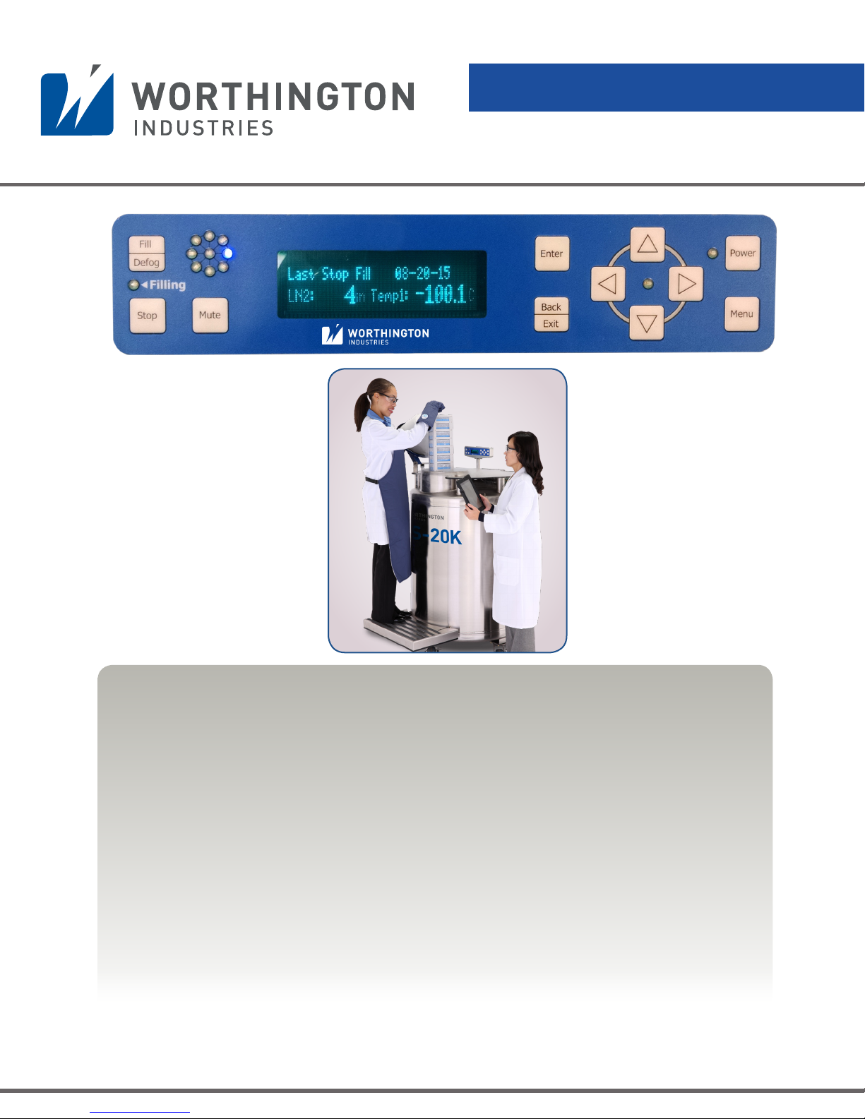
CS200 Control Systems
LABS and K Series Cryostorage Systems
Operation & Maintenance Instructions
CAUTION - SAFETY FIRST!
• REVIEW AND UNDERSTAND ALL SAFETY PROCEDURES IN THE “HANDLE WITH CARE”
BOOKLET BEFORE ATTEMPTING TO INSTALL, OPERATE OR PERFORM MAINTENANCE
ON THIS LN2 CONTROLLER.
• DO NOT ATTEMPT TO USE OR MAINTAIN ANY LIQUID NITROGEN FREEZER UNTIL YOU
READ AND UNDERSTAND THESE INSTRUCTIONS.
• DO NOT PERMIT UNTRAINED PERSONS TO USE OR MAINTAIN THIS UNIT.
• IF YOU DO NOT FULLY UNDERSTAND THESE INSTRUCTIONS, CONTACT YOUR
SUPPLIER FOR FURTHER INFORMATION.
• BEFORE ATTEMPTING TO OPERATE THIS CONTROLLER WITH ANY WORTHINGTON
INDUSTRIES LABS OR K SERIES UNITS, YOU MUST READ THE SEPARATE OPERATING
AND SAFETY MANUAL PROVIDED WITH THAT UNIT.
Page 2

Page 3

Table of Contents
SAFETY PRECAUTIONS .......................................................................5
Liquid Nitrogen (LN2) ............................................................................................. 5
Extreme Cold - Cautionary Statement ....................................................................... 5
Keep Equipment Area Well Ventilated ..................................................................... 5
Liquid Nitrogen System ......................................................................................... 5
Electrical .............................................................................................................. 5
GENERAL INFORMATION ...................................................................6
CS200 Series Control System Specifications ............................................................ 7
DELIVERY AND RETURNS .................................................................. 10
Unpacking and Inspection .................................................................................... 10
Freight Damage Procedures ................................................................................. 10
Repackaging for Shipment .................................................................................. 10
INSTALLATION ................................................................................. 11
Getting Unit into Service ..................................................................................... 11
Electrical ........................................................................................................... 11
Electromagnetic Compatibility (EMC) .................................................................... 11
Power Supply Connection ................................................................................... 12
Validation .......................................................................................................... 12
OPERATION ....................................................................................13
Initial Fill ........................................................................................................... 13
Control Components ........................................................................................... 13
CS200 Controller Display Guide ........................................................................... 14
Operational Theory ............................................................................................. 14
Alarm Conditions ............................................................................................... 15
Lid Switch .......................................................................................................... 16
Solenoid Valve ................................................................................................... 17
Thermocouples ................................................................................................... 17
Power Supply .................................................................................................... 17
Remote Alarm .................................................................................................... 17
Operating Parameters ......................................................................................... 17
Temperature Monitoring ....................................................................................... 18
Liquid Phase Storage ........................................................................................... 18
Maintenance ...................................................................................................... 18
CONTROLLER OPERATION ................................................................20
Introduction ....................................................................................................... 20
Operation Data .................................................................................................. 20
Communications ................................................................................................. 20
Normal Fill Cycle ............................................................................................... 20
Control Setting Adjustments .................................................................................. 20
Temperature .......................................................................................................26
Battery Operation .............................................................................................. 26
LED Status Wheel ............................................................................................... 26
Lid Switch ........................................................................................................... 26
Menu System ..................................................................................................... 27
Factory Defaults ................................................................................................. 29
Troubleshooting ..................................................................................................30
Interconnection Block Diagram .............................................................................. 30
CS200 Control Systems
Page 4

Table of Contents
Wiring Diagram ..................................................................................................31
Installation & Setup .............................................................................................. 32
External Connector Ratings ................................................................................... 34
LED Status Wheel Flash Patterns ............................................................................ 35
Temperature Thermocouple Select ......................................................................... 35
Temperature Calibration ...................................................................................... 35
Test Temperature System ....................................................................................... 36
Test Level Sensors ................................................................................................ 36
Alarms and Error Conditions ................................................................................ 37
System Alarms .................................................................................................... 37
Test Alarms ........................................................................................................ 37
Logging ............................................................................................................. 37
Display Brightness ............................................................................................... 38
Making Adjustments to the CS200 Series Control System Sensor Assembly ............... 38
Removing/Installing the Solenoid Valve ................................................................. 39
Removing/Installing the Controller 10K/24K Units ................................................. 39
Removing/Installing the Thermocouple .................................................................. 40
Removing/Installing the Sensor Probes .................................................................. 40
Making Adjustments to the Level Settings ............................................................... 40
Removing/Installing the Solenoid Valve ................................................................. 41
REPLACEMENT PARTS ...................................................................... 42
Plumbing Assembly ............................................................................................. 42
Controller Assembly ............................................................................................ 43
TROUBLESHOOTING ........................................................................45
Symptoms ......................................................................................................... 45
Controller Will Not Turn ON ............................................................................... 45
High Liquid Level ................................................................................................ 45
Indicates Low LN2 Supply ..................................................................................... 46
Indicates Open Sensor ......................................................................................... 46
Temperature Reading 10° to 20° Warm ................................................................. 46
Fill Solenoid Cycles On and Off ............................................................................ 47
Solenoid Makes Excessive Humming Noise ............................................................ 47
Lid Open Alarm .................................................................................................. 47
QCF (Quick Chill Feature) Will Not Operate ......................................................... 47
Auto Defog Feature Will Not Operate ..................................................................47
Push Buttons Will Not Respond ............................................................................48
Liquid Level Readout is Incorrect ........................................................................... 48
Power Failure Alarm ........................................................................................... 48
SERVICE AND MAINTENANCE HISTORY LOG ....................................49
APPENDIX ....................................................................................... 50
EN Compliance Tables .........................................................................................50
EC Declaration of Conformity ............................................................................... 54
Warranty ........................................................................................................... 55
Labels ................................................................................................................ 55
CS200 Control Systems
Page 5

Safety Precautions
Liquid Nitrogen
Nitrogen is an inert, colorless, odorless, and tasteless gas making up four-fifths of the
air you breathe – and can be very dangerous. Air is roughly one-fifth oxygen. Liquid
nitrogen is at a temperature of -196°C (-320°F) under normal atmospheric pressure.
Cryogenic freezers are used in LN2 service only.
Extreme Cold - Cautionary Statement
Accidental contact of liquid nitrogen or cold issuing gas with the skin or eyes may
cause a freezing injury similar to frostbite. Handle the liquid so it won’t splash or
spill. Protect your eyes and cover the skin where the possibility of contact with the
liquid, cold pipes and equipment, or cold gas exists. Safety goggles or a face shield
should be worn when operating this equipment. Insulated gloves that can be easily
removed and long sleeves are recommended for arm protection. Trousers without
cuffs should be worn outside boots or over the shoes to shed spilled liquid.
Keep Equipment Area Well Ventilated
Although nitrogen is non-toxic and non-flammable, it can cause asphyxiation in
a confined area without adequate ventilation. Any atmosphere not containing
enough oxygen for breathing can cause dizziness, unconsciousness, or even death.
Nitrogen, a colorless, odorless, and tasteless gas that cannot be detected by the
human senses, will be inhaled normally as if it were air. One (1) liter of liquid
nitrogen is equivalent to 24.6 scf of nitrogen gas. Without adequate ventilation, the
expanding nitrogen will displace the normal air resulting in death.
Liquid Nitrogen System
The liquid nitrogen supply pressure at the inlet to the freezer should be in the
range of 10 psig (0.7 bar/69 kPa) to 20 psig (1.4 bar/138 kPa) for optimum
performance. Higher operating pressures will increase transfer losses and create
excessive turbulence of the liquid in the freezer, which can generate false signals
to the liquid level controller causing the freezer to under-fill. In “liquid phase”
storage applications, excessive turbulence can cause splashing which could result
in personal injury and/or damage to the freezer. When installing piping or fill hose
assemblies, make certain a suitable safety relief valve is installed in each section
of plumbing between any two isolation points. Trapped liquefied gas will expand
greatly as it warms and may burst hoses or piping causing damage or personal
injury. A relief valve is installed in the freezer plumbing to protect the line between
the customer-supplied shut-off valve and the freezer solenoid valve. Relief valves can
be piped to the outside of the building.
WARNING:
The following safety
precautions are for
your protection. Before
installing, operating,
or maintaining this unit
read and follow all
safety precautions in this
section and in reference
publications. Failure
to observe all safety
precautions can result
in property damage,
personal injury, or
possibly death.
WARNING:
Maintain adequate
ventilation to prevent
asphyxiation hazard
(see Safety Precautions).
Caution:
When installing field
fabricated piping, make
certain a suitable safety
relief valve is installed
in each section of piping
between any two
isolation points.
WARNING:
Inlet pressure should not
exceed 22 psig
(1.5 bar/152 kPa).
Higher pressures could
result in damage to
equipment.
Electrical
• This product is not intended for a life support function.
• This product is intended to be used in hospitals and clinics.
• This product has no Radio Transmitter (Intentional Radiator) functions.
• This product is not intended for electromagnetic shielded rooms only.
WARNING:
Electrical shock can
kill. Do not attempt
any service on these
units without first
disconnecting the
electrical power cord.
CS200 Control Systems
5
Page 6

General Information
• This product does not intentionally apply RF energy for its function.
• This product does not intentionally receive RF energy for its function.
The liquid level controllers used with these freezers operate from 12 VDC. Disconnect the electrical power cord
from the outlet before attempting any service.
For more detailed information concerning safety precautions and safe practices to be observed when handling
cryogenic liquids consult CGA publication P-12 “Safe Handling of Cryogenic Liquids” available from the
Compressed Gas Association: CGA website: www.cganet.com; CGA customer service +1.703.788.2700; or
email [email protected].
General Information
The CS200 SERIES Control System can monitor and control both the liquid nitrogen level and the vapor
temperature range in the cryostorage unit you have selected. CS200 SERIES Control Systems are designed
to work with Worthington Industries Cryostorage Systems. The features are designed to provide a safe
environment for samples while at the same time tracking all relevant information associated with the freezer.
This control provides a complete historical record of the environment in your unit and therefore, the environment
in which your samples have been stored in this system. This controller features a vacuum fluorescent display.
The addition of a liquid nitrogen supply and inventory control racks for systematic retrieval of stored product
completes the total Cryostorage System.
Worthington Industries Cryostorage Systems are designed for applications where extremely low temperature
storage of biological products is required. They are also appropriate for industrial or other applications where
liquid nitrogen temperatures and high capacity are needed.
Before beginning installation or operation of this CS200 SERIES Control System, make sure that you read and
understand this manual as well as the operating and safety instructions for the cryostorage unit you will be
using with this controller.
CS200 Control Systems
66
Page 7
General Information
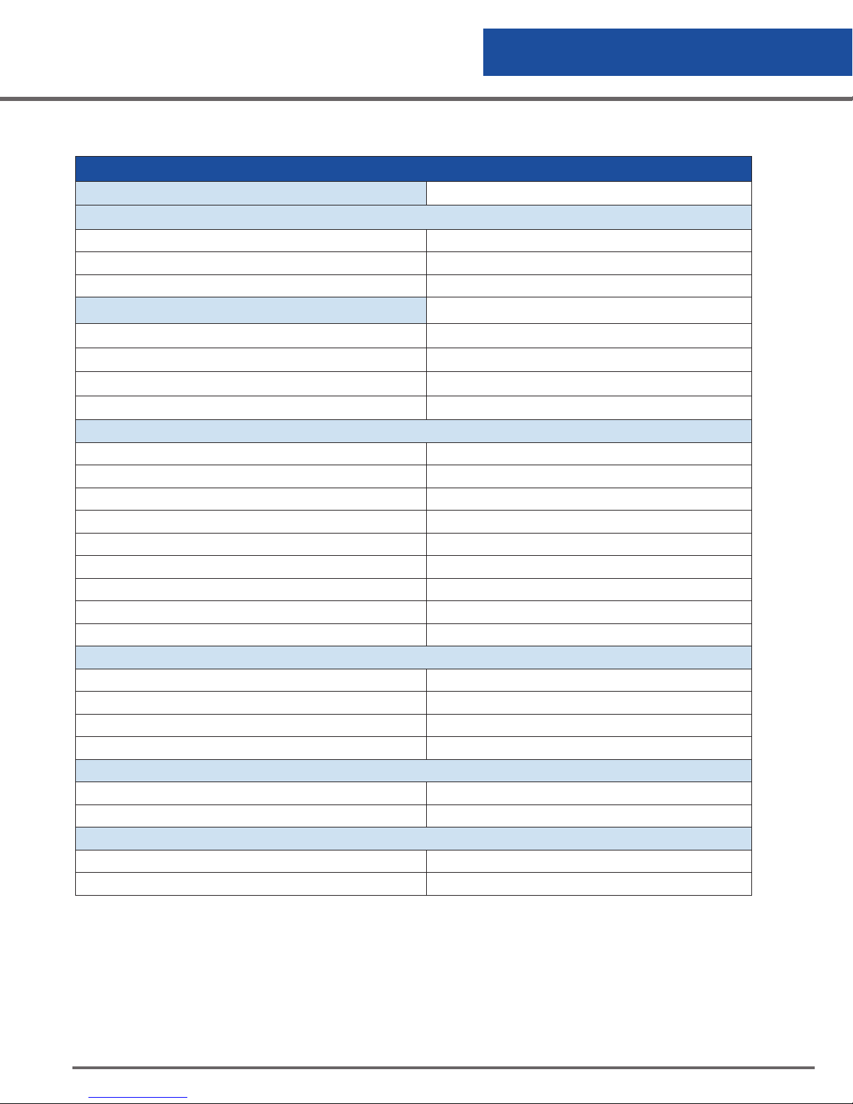
CS200 SERIES Control System Specifications
Specifications
Control Type LN2 Level Control & Temperature Control
Level Measurement
Sensor Type 8-Thermistor Fixed (standard)
Range 8 inch range (8-Thermistor)
Redundancy Multiple discrete points
Temperature Measurement Sensor Type
Type T Thermocouple
Accuracy
Resolution
Number of channels
Temperature Display Units
Electrical
Input Voltage 100-240 VAC
Input Current (max) 1.75 A
Input Current (continuous) .5 A
Power Consumption (max) 21 W
Power Consumption (continuous) 6 W
Input Frequency 50/60 Hz
Output 12 VD C
Control Input Voltage 12 VD C
Power cord Available for all countries
Battery
Rating 12 Volt, 18Ah
Type AGM Sealed Non-Spillable
Short Protection Installed PCB with thermal fuse
Battery Cover Vinyl
Solenoid Valve
Input Voltage 12 VD C
Input Current .96 amps
Communications
Protocol CryoWire Secure™
Number of Communication Ports 3
1o or 1.5% of reading
.1oC
2
o
C, F, K, R
CS200 Control Systems
7
Page 8
General Information
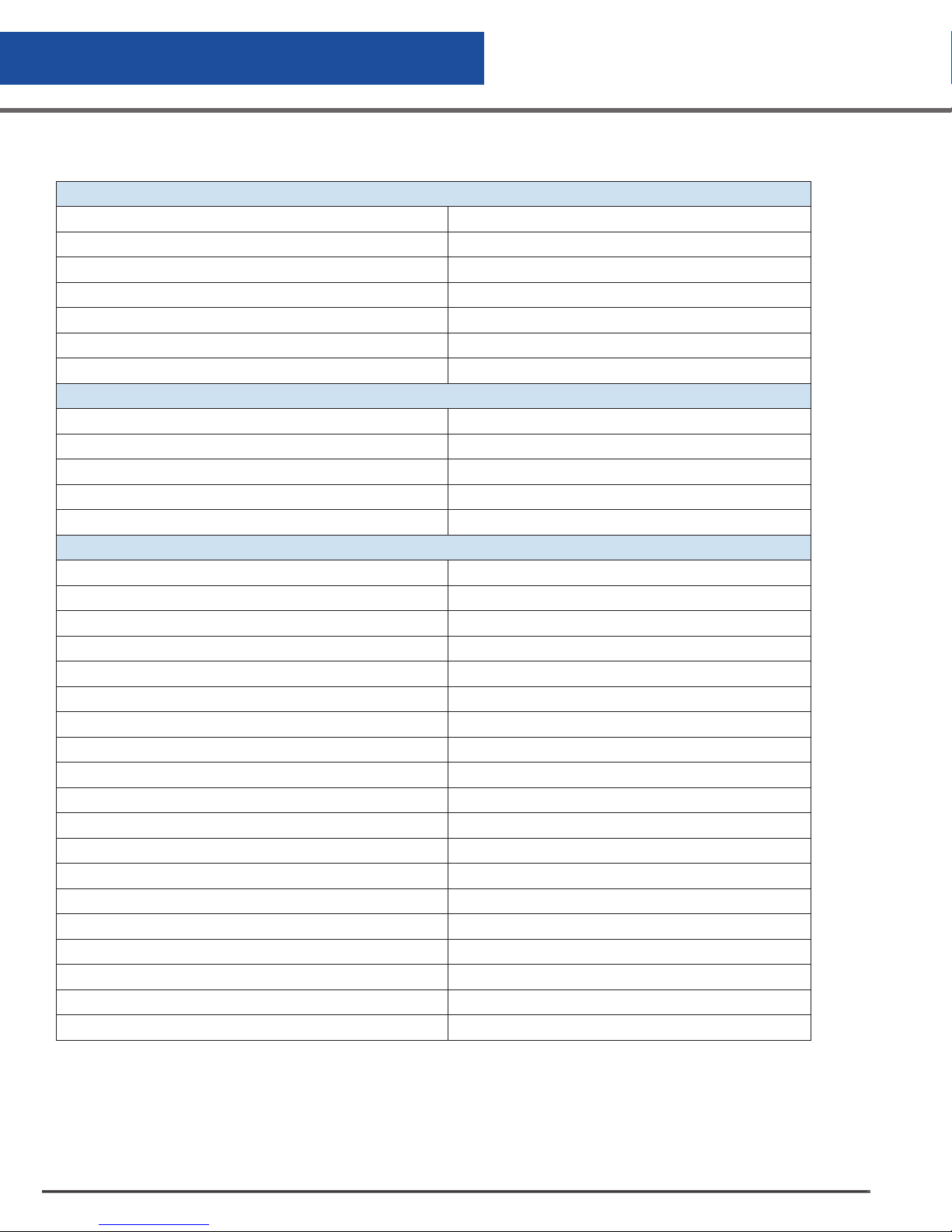
CS200 SERIES Control System Specifications (cont’d)
User Interface
Display Type Vacuum Fluorescent Display (VFD)
Buttons 11
Level, Temperature and Alarm Information VFD
“At a Glance” status LED status wheel
Filling 1 LED
Menu Access 1 LED
Language English and German
Control Tests
Power Up Self-Test Control system check
Thermistor Status Yes
Battery voltage Yes
Control voltages Yes
Temperature circuit Yes
Alarms
Low Level Alarm Always enabled
High Level Alarm Always enabled
Sensor Error Alarm Always enabled
High Temperature Alarm (T/C #1, T/C #2) Programmable
Low Temperature Alarm (T/C#1, T/C#2 ) Programmable
Thermocouple Calibration Alarm Always enabled
Thermocouple Open Alarm Always enabled
Power Failure (Remote only) Always enabled
Low LN2 Supply Alarm Programmable
Battery Mode Warning Always enabled
Lid Open Too Long Alarm Programmable
Valve Stuck Open Alarm Programmable
Unauthorized Access Warning Programmable
LN2 Use Warning Programmable
Low Battery Voltage Always enabled
Audible Alarm Always enabled
Audible Alarm Re-trigger Programmable
Visual Alarm Indicator Always enabled
Remote Alarm Delay Programmable
CS200 Control Systems
8
Page 9
General Information
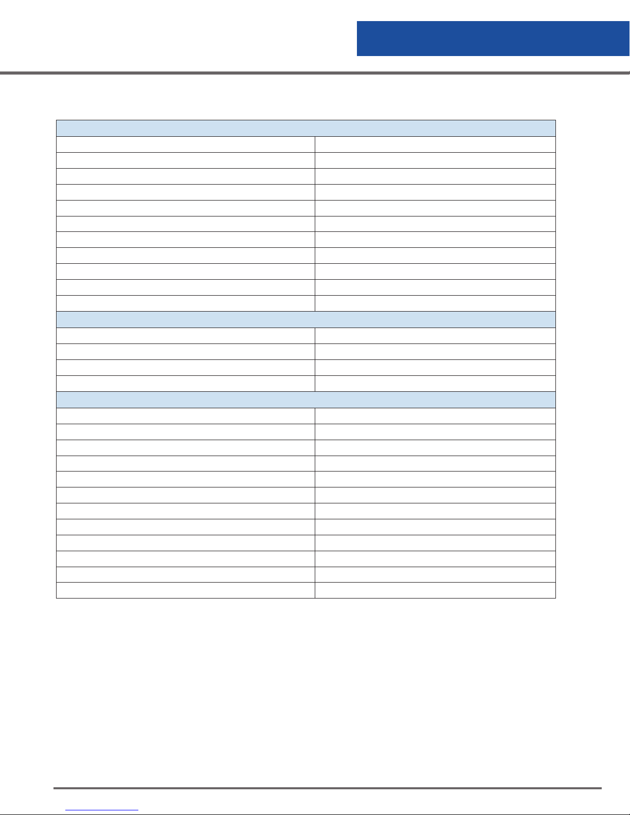
CS200 SERIES Control System Specifications (cont’d)
Buttons
Power Turns power on/off
Fill/Defog Open Valve
Stop Close Valve
Menu Access Menu
Mute Silence audible
Enter Save a setting or select a menu choice
Back/Exit Leave a setting unchanged or back out of menu.
Up arrow Scroll the menu system or increase a value
Down arrow Scroll the menu system or decrease a value
Left arrow Scroll horizontal menu
Right arrow Scroll horizontal menu
Data Collection
Temperature Yes
Level Yes
Alarms Yes
Memory 4 Mb
Dimensions
Display Width 9.5” (241 mm)
Display Height 2.0” (50.8 mm)
Display Depth 1.31” (33.3 mm)
Display Weight .625 lbs (.28 kg)
Main Control Width 8.875” (225.4 mm)
Main Control Height 6.688” (169.9 mm)
Main Control Depth 1” (25.4 mm)
Main Control Weight 1.0 lbs (.45 kg)
Battery Width 7.25” (184.2 mm)
Battery Height 6.375” (161.9 mm)
Battery Depth 3.25” (82.6 mm)
Battery Weight 12.4 lbs (5.6 kg)
NOTE: Above measurements are for LABS; CS200 controllers are integrated into all K Series models.
CS200 Control Systems
9
Page 10

Delivery & Returns
Unpacking and Inspection
Inspect shipping containers for external damage. All claims for damage (apparent or concealed) or partial loss
of shipment must be made in writing within ten (10) days from receipt of goods. If damage or loss is apparent,
please notify the appropriate parties as indicated below:
Domestic LTL Shipments – The customer should notify and file the appropriate damage claims with the
carrier. All products are shipped Ex Works.
Domestic UPS Shipments – Any damage should be noted and reported to shipper upon delivery, and
Worthington Industries must also be notified. Confirm with Worthington Industries Customer Service the filing
procedures for any UPS damage claims.
International Shipments – Any damage and/or claims are to be filed with the carrier. Insurance agent(s)
and Customs should also be notified.
In all cases, Worthington Industries should be notified so we can assist if needed in filing
damage claims.
Open the shipping containers; a packing list is included with the system to simplify checking that all
components, cables, accessories, and manuals were received. Please use the packing list to check off each
item as the system is unpacked. Inspect for damage. Be sure to inventory all components supplied before
discarding any shipping materials. If there is damage to the system during transit, be sure to file proper claims
promptly. Please advise Worthington Industries of such filings. In case of parts or accessory shortages, advise
Worthington Industries immediately. Worthington Industries cannot be responsible for any missing parts unless
notified within 10 days of shipment.
Freight Damage Procedures
Any freight damage claims are your responsibility. Cryostorage Systems are delivered to your
carrier from Worthington Industries’ dock in new condition; when you receive our product
you may expect it to be in that same condition. For your own protection, take time to visually inspect
each shipment in the presence of the carrier’s agent before you accept delivery. If any damage is observed,
make an appropriate notation on the freight bill. Then, ask the driver to sign the notation before you receive the
equipment. You should decline to accept containers that show damage which might affect serviceability.
Repackaging for Shipment
If it is necessary to return any part of the system for repair or replacement, a Material Return Authorization
(MRA) number must be obtained from an authorized factory representative before returning the equipment
to our service department. Contact your distributor for return authorization. When returning equipment for
service, the following information must be provided before obtaining an MRA:
1. System model and serial number, and controller model and serial number.
2. User’s name, company, address, and phone number
3. Malfunction symptoms
If possible, the original packing material should be retained for reshipment. If not available, consult
Worthington Industries for shipping and packing instructions. It is the responsibility of the customer to assure
that the goods are adequately packaged for return to the factory. All freezers returned to Worthington Industries
must be clean and decontaminated before return.
CS200 Control Systems
10
Page 11

Installation
Getting Unit into Service
Your Cryostorage System comes with complete instructions for how you should
remove the unit from the crate and put it into service. Read both this manual and
your Cryostorage System’s manual before beginning any installation. Make sure to
follow any required procedures and safety guidelines when you are connecting your
Liquid Nitrogen source.
The CS200 SERIES Control System is designed to be operated at normal room
temperatures 15° C to 27° C (60° F to 80° F) at a relative humidity level below
50%. The humidity level should be maintained such that the electronics are not
exposed to condensation.
The Worthington Industries Cryostorage freezer should be positioned such that the
all sides of the unit are easily accessible and the user can easily connect/disconnect
the power cord from the wall socket.
Proper ventilation MUST BE adequate to sustain life for those working with or
maintaining this equipment.
Electrical
The liquid level controllers used with these freezers operate at 12 VDC. The external
power supply has a 120 VAC (50/60 Hz) primary. Disconnect the electrical power
cord from the wall outlet before attempting any service.
Electromagnetic Compatibility (EMC)
Although this equipment conforms to the intent of the 2004/108/EC EMC Directive,
all medical equipment may produce electromagnetic interference or be susceptible
to electromagnetic interference. The following are guidance and manufacturer’s
declarations regarding EMC for the CS200 SERIES Control System.
WARNING:
Electrical shock can
kill. Do not attempt
any service on these
units without first
disconnecting the
electrical power
cord.
The CS200 SERIES Control System needs special precautions regarding EMC
and needs to be installed and put into service according to the EMC information
provided in the following pages.
Portable and Mobile RF communications equipment can affect the performance of
the CS200 SERIES Control System. Please use the guidelines and recommendations
specified in the EN Compliance tables found on pages 50-54.
Other equipment or systems can produce electromagnetic emissions and therefore
can interfere with the functionality of the CS200 SERIES Control System. Care
should be used when operating the CS200 SERIES Control System adjacent to or
stacked with other equipment. If adjacent or stacked use is necessary, the CS200
SERIES Control System should initially be observed to verify normal operation in the
configuration in which it will be used.
The electrical cables, external power supplies and accessories listed or referenced
in this manual have been shown to comply with the test requirements listed in the
EN Compliance tables found on pages 50-54. Care should be taken to use only
manufacturer-recommended cables, power supplies and electrical accessories with
the C200S SERIES Control System. If a third-party supplier offers cables, external
WARNING:
Maintain adequate
ventilation
to prevent
asphyxiation
hazard (see Safety
Precautions).
WARNING:
If the fill fails to
stop for any reason,
quickly close the
liquid supply
valve to prevent
overfilling until the
the problem can be
determined.
CS200 Control Systems
11
Page 12

Installation
WARNING:
This equipment
is intended for
use by healthcare
professionals. As
with all electrical
medical equipment,
this equipment
may cause radio
interference or
may disrupt the
operation of nearby
equipment. It may
be necessary to
take mitigation
measures such
as re-orienting
or relocating the
CS200 SERIES
Control System unit
or shielding the
location.
power supplies and electrical accessories for use with the CS200 SERIES Control
System and they are not listed or referenced in this manual, it is the responsibility of
that third-party supplier to determine compliance with the standards and tests in the
EN Compliance tables found on pages 50–54.
The use of electrical cables and accessories other than those specified in this manual
or referenced documents may result in increased electromagnetic emissions from the
CS200 SERIES Control System or decreased electromagnetic immunity of the CS200
SERIES Control System.
Power Supply Connection
Connect the power supply to your Cryostorage System and then plug the power
supply into a surge-protected wall outlet.
Validation
Some organizations require that equipment be validated periodically. If information
is needed on the proper techniques to validate this equipment, please contact your
supplier.
CS200 Control Systems
1212
Page 13

Operation
These instructions are for operators experienced with cryogenic equipment. Before operating the system,
become familiar with the safety precautions in this manual and in reference publications. Make certain all
applicable provisions set forth in the Installation Section have been followed before placing a system in
operation. Study this manual thoroughly. Know the location and function of all system components.
Initial Fill
The Cryostorage System, using the CS200 SERIES Controller, comes preset from the factory. The liquid nitrogen
supply pressure at the inlet to the freezer should be in the range of 10 psig (0.7 bar/69 kPa) to 22 psig
(1.5 bar/152 kPa) for optimum performance. Higher operating pressures will increase transfer losses and
create excessive turbulence of the liquid in the freezer which can generate false signals to the liquid level
controller causing the freezer to under fill. In “liquid phase” storage applications, excessive turbulence can
cause splashing which could result in personal injury.
Control Components
CS200 Series Control System Components
The CS200 SERIES Control System for the Worthington Industries Cryostorage freezer consists of the following
components:
• Main Control Module
• VFD (Vacuum Florescent Display) Module
• Shielded Display Cable
• Wiring Harness Assembly
• Power Supply
• Thermocouple Assembly (Optional Second Thermocouple)
• Sensor Assembly
• Cryogenic Solenoid Valve
• Remote Alarm Plug
• Lid Switch Assembly
• 12 Volt, 18aH battery
• Solenoid Valve Assembly with Freezeguard
• Strainer
The CS200 Series Control System is assembled onto the freezer at the factory and completely tested. Refer to
the Quick Start Guide for freezer set-up. Start operation of the control system by plugging the power cord into
the wall outlet. Press and hold the POWER button for 2 seconds. The CS200 Series Control System will go
through a short startup routine and then start operation. Refer to Figure 2.0 CS200 Controller Display for a
description of the controller’s navigation buttons.
CS200 Control Systems
13
Page 14
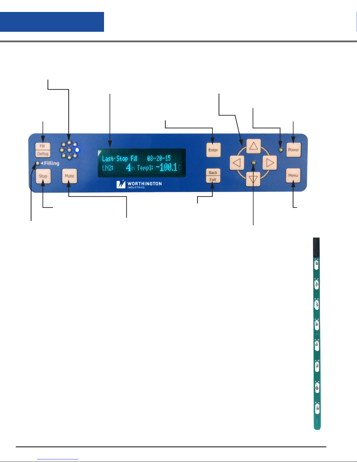
Operation
CS200 Controller Display Guide
Status Wheel
VFD Graphics Display
shows information about
the freezer
Fill button
usend to open
the valve
Enter Button “selects”
a menu choice or setting
Stop Button used
to close the valve
Mutes the
Valve Indicator lights
audible alarm
if the valve is open
Figure 1.0 CS200 Controller Display
Directional Buttons
Increment/decrement values or
allow movement through the system
Power Indicator
Back Button
moves out of the
menu system or
leaves current set-
Menu Indicator
ting unchanged
Power On/Off
Enter/Exit
menu system
Operational Theory
The CS200 SERIES Control System automatically maintains the Liquid Nitrogen (LN2) level
and monitors temperature in the Cryostorage freezer. Operational conditions are monitored
and any alarm is triggered if necessary. Operations data is stored in memory on the control
board.
The CS200 CONTROL SYSTEM uses thermistors to measure the LN2 level within the vessel.
A thermistor is a thermal resistor and its resistance changes as the temperature changes.
When a thermistor is submerged in LN2, its resistance will be significantly greater than its
resistance at room temperature. The control can detect this resistance change and determine
the level of the LN2 within the freezer. The CS CONTROL SYSTEM is designed to work with
an 8-thermistor assembly. There are four thermistors that can be selected to maintain the LN2
level. These selected thermistors correspond to Low Alarm, Start Fill, Stop Fill and High Alarm.
When the LN2 level drops below the Start Fill thermistor, the control opens the solenoid valve
allowing LN2 to enter the vessel. This continues until the Stop Fill thermistor is submerged in
LN2 at which point the solenoid valve is closed, preventing the flow of additional LN2 into the
vessel. The Low Alarm, Start Fill, Stop Fill and High Alarm settings can all be changed by the
user through the menu system.
High Level
High Level A
Low Level
Low Level A
Alarm
Alarm
#8
#7
#6
#5Stop Fill
#4
#3Start Fill
#2
#1
CS200 Control Systems
14
Figure 2.0 Factory Default Settings Shown
Page 15
Operation
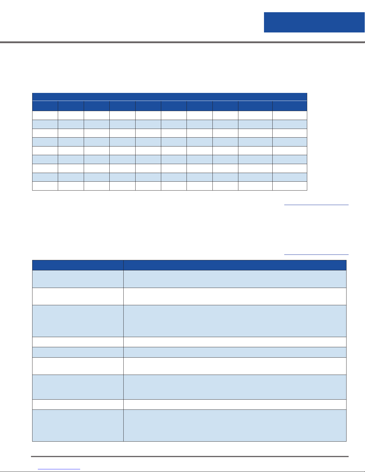
The LN2 level is indicated on the display and is determined by the number of
thermistors submerged in LN2 according to the table below:
Table 1.0 8-Thermistor Sensor (G=GAS, L=LIQUID)
8-THERMISTOR SENSOR
#1 #2 #3 #4 #5 #6 #7 #8 OFFSET DISPLAY
G G G G G G G G 0 0
L G G G G G G G 0 1
L L G G G G G G 0 2
L L L G G G G G 0 3
L L L L G G G G 0 4
L L L L L G G G 0 5
L L L L L L G G 0 6
L L L L L L L G 0 7
L L L L L L L L 0 8
NOTE - Offset value for LABS94K only = 3.0 in (126 mm).
Alarm Conditions
The CS200 SERIES Control System monitors a number of conditions and provides an
alarm if a problem is detected. The alarms are listed below:
Table 2.0 Alarm Conditions
Note: Please see
description of
the offset. Level
displayed may vary
depending on the
offset setting.
Alarm Problem Detected
Low Level Alarm
High Level Alarm
Sensor Error Alarm
High Temperature Alarm The temperature detected is warmer than the high temperature alarm setting.
Low Temperature Alarm The temperature detected is colder than the low temperature alarm setting.
Thermocouple Calibration
Alarm
Thermocouple Open Alarm
LN2 level is too low. The low level alarm thermistor on the sensor assembly is not
submerged in LN2.
LN2 level is too high. The high level alarm thermistor on the sensor assembly is
submerged in LN2.
A problem exists with the level sensor assembly. The control detects an open sensor
circuit meaning that the sensor is unplugged or the sensor assembly has been
damaged. A Sensor Error will be represented by an “O” within the Thermistor Status
menu.
The calibration data is incorrect.
A problem exists with the temperature sensor (thermocouple). The control detects an
open circuit meaning that the sensor is unplugged or the sensor assembly has been
damaged.
Power Failure No Power.
Low LN2 Supply Alarm
A problem may exist with the LN2 supply connected to the freezer. This alarm occurs
if the freezer does not fill within the designated amount of time as determined by the
setting on the control. This may occur for a number of reasons including an empty
supply cylinder, low pressure in the supply cylinder or a closed shut off valve.
CS200 Control Systems
15
Page 16
Operation
Alarm Problem Detected
Lid Open Too Long Alarm
Valve Stuck Open Alarm The solenoid valve is stuck open.
Unauthorized Access Warning The lid has been opened and an incorrect identification has been entered.
LN2 Usage Warning The consumption of LN2 has increased and should be checked.
Low Battery Voltage The voltage on the battery is low.
The lid has been opened for a period which is longer than the designated alarm
setting.
Audible Alarm Retrigger
Remote Alarm Relay
Operating in Battery Mode Alarm
Warning
The audible alarm is retriggered if error conditions still exist when the retrigger timer
expires. The retrigger time can be adjusted by the user.
The control provides a relay to provide an external signal that an alarm condition
has occurred. The remote alarm timer can be set through the menu system. This
setting determines the amount of time an error must be active before the relay is
triggered.
The power from the power supply has been disrupted and the control system is operating on battery power.
All alarms include the following:
• The flashing status wheel flashes to signal an error condition
• An audible tone sounds
• The error detected is displayed and scrolled on the screen
• The remote alarm relay changes state to provide a dry contact output signal
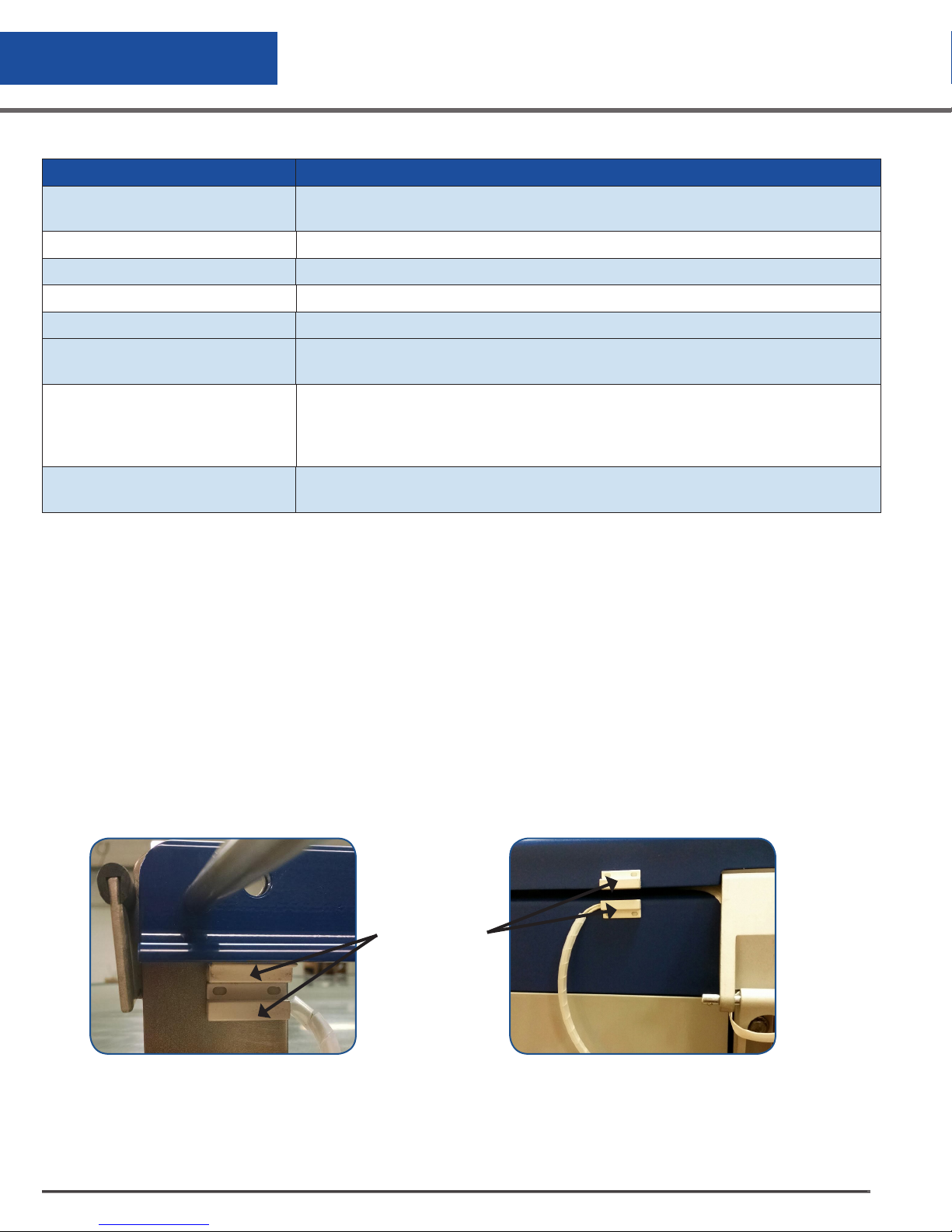
Lid Switch
The Lid Switch (Figure 4.0 and 4.1) is attached to the hinge and determines whether or not the lid is open on
the freezer. This also allows the control to determine whether to activate the Auto Defog, Quick Chill or Lid
Alarm features.
CS200 Control Systems
16
Lid Switch
Figure 3.1 K Series Lid SwitchFigure 3.0 LABS Lid Switch
Page 17
Operation
Solenoid Valve
These units are designed to work with 12 VDC solenoid valve (see Figures 17.0, 17.1, and 17.2 Plumbing
Assemblies on page 42).
Thermocouples
Type T thermocouples monitor the temperature in the freezer. The user may choose to use NONE, 1 or 2
thermocouples with this control at any time. (The unit comes complete with one Thermocouple)
Power Supply
A 12 VDC power supply is supplied for the CS200 SERIES Control System. This system is supplied with a
universal power supply that accepts 100/240 VAC (50/60 Hz). UL approval for the system as a whole is not
required since the control operates on low voltage. If your power source differs, or is subject to disruption or
line surges due to other equipment on line, consult your Worthington Industries representative.
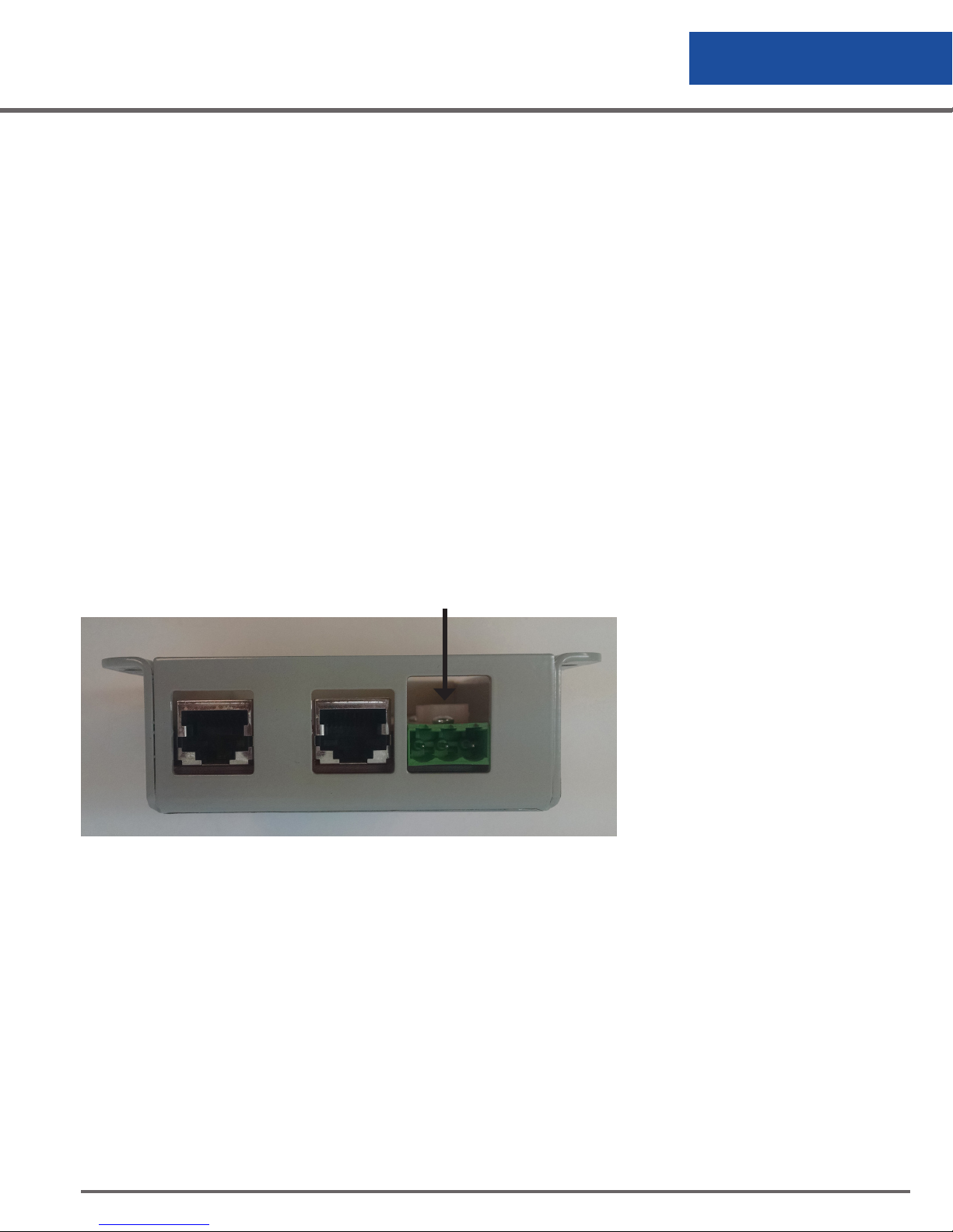
Remote Alarm
If an error condition occurs after a user defined period of time, a remote alarm can be initiated. This is
accomplished by connecting a remote device to the remote alarm jack on the rear electrical panel. The 3-pin
jack on the back of the unit provides continuity between pin #2 (common) and pin #3 in the normal condition.
Continuity between pin #1 and pin #2 is provided in an error condition.
Remote Alarm Connector
Figure 4.0 Remote Alarm Plug Connection
Operating Parameters
When materials are immersed in LN2, they will assume the temperature of the liquid (-196°C/-320°F). When
material is stored in the vapor phase over the liquid, the liquid nitrogen vapor is still a very cold refrigerant,
but the freezer’s interior temperature increases as product is stored higher above the liquid. This temperature
differential is not significant for many biological storage applications, and is affected by the amount of product
stored in the freezer, the type, size and material of the inventory control system, and the liquid level in the unit.
The liquid level in the freezer is determined by the position of the of the Thermistor Assembly in the sensor tube.
These sensors are set at installation to maintain a specific liquid level. A filling cycle is initiated when the level
falls below the Start Fill sensor and is completed when the Stop Fill sensor is reached. This filling cycle repeats
when the level fall below the Start Fill sensor. Sensor Probe assignments may be changed on the controller
CS200 Control Systems
17
Page 18

Operation
keypad to define new start and stop levels, and these levels may be set independently to vary the liquid level
deference between fills. Prior to the initial fill of the freezer, a determination should be made whether vapor
phase or liquid phase storage will be utilized.
All units are supplied with an eight-thermistor assembly and a freeze-guard sensor unless otherwise specified.
The LABS factory setting positions will maintain liquid level within a distance of 2 in. (51 mm) from the bottom
of the carousel on the LABS 20K, 38K, 40K, 80K units, and 3 in. (76 mm) from the bottom of the carousel on
the LABS 94K. The K Series factory setting positions will maintain liquid level settings between 3 in. (76 mm)
and 6 in. (152 mm).
Temperature Monitoring
The CS200 SERIES Control System uses a Type T thermocouple to monitor the temperature in the vessel. The
thermocouple is factory-installed near the top of the Worthington Industries Cryostorage freezer vapor chamber
and the temperature is measured at that point.
The CS200 SERIES Control System accommodates a second thermocouple (optional) for temperature
measurement at a secondary location. This requires a Type T thermocouple.
The control provides a High Temperature Alarm for each thermocouple which can be selected by the user.
If the temperature exceeds the temperature alarm set point, the status wheel flashes and an audible alarm is
triggered.
Liquid Phase Storage
Liquid phase storage is normally utilized when (-196°C/-320°F) is required to maintain stored product viability
and the storage medium is adequate for storage in LN2. In a typical liquid phase storage system, the liquid
level sensors are positioned to maintain the liquid level at or below the top level of the inventory control
system. During operation, the upper levels of the inventory control system will at times become exposed as the
liquid level fluctuates.
Care must be taken to ensure that the liquid level remains below the bottom of the freezer lid. Exposure
to LN2 may result in physical damage to the lid. Additionally, operating the freezer with high liquid levels
characteristic of liquid phase storage may result in turbulence during fill cycles. Caution must be exercised if
the freezer lid is opened during a fill, and appropriate safety equipment should always be worn.
The Worthington Industries Cryostorage Systems are factory set for vapor phase storage.
Maintenance
To insure proper operation and maintain excellent performance of the Worthington Industries Cryostorage
freezer, an annual maintenance schedule should be followed for the CS200 SERIES Control System. This would
include the following:
CS200 Control Systems
18
Page 19
Operation
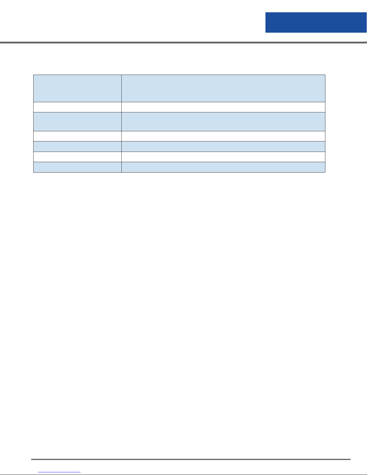
Table 3.0 Annual Maintenance Schedule
CS200 SERIES Control Examine for exposure to moisture, wear and tear, connector problems, and
damage to the faceplate or buttons. In addition, periodic firmware updates
may be important
Harness Assembly Examine for damage to the cable and damage to connectors,
Battery Examine connection cable and connector for damage. Examine vinyl
cover for damage. Replace every 3 years
Solenoid Valve Examine wires and connector for damage. Replace every 2 years.
Lid Switch Examine lid switch pickup and wires for damage. Replace if necessary
Level Sensor Assembly Examine for damage to wires and connector. Replace every 3 years
Thermocouple Assembly Examine for damage to wires and connector.
In addition, inspection and preventive maintenance should also be performed on the freezer and its
mechanical parts. Refer to owner’s manual for details.
If any intermittent alarm or defect with the Cryostorage System is observed or suspected, it should be
investigated and remedied immediately even if this falls outside of the normal maintenance schedule.
CS200 Control Systems
19
Page 20

Controller Operation
This section of the operating manual is for Worthington Industries approved equipment that uses the CS200
SERIES Control System.
Introduction
The CS200 Control System, temperature and LN2 level controller is designed for easy operation and reliable
uninterrupted service. This controller will maintain the selected liquid level range of LN2 in your freezer as
well as providing audible and visual alarms for any non-conforming conditions that may occur. An Alarm is
any condition outside the activated preset limits on the control, such as an open sensor circuit or temperature
alarm. “System Events” are lid openings and closings, solenoid valve openings and closings, and operation
of the controller’s relay for remote alarm indication. System Events, Alarms and Temperature “Data” can be
downloaded.
The System should require no additional attention to maintain liquid level if an adequate supply source of
liquid nitrogen is available. If your protocol calls for you to “top-off” the Cryostorage System at the end of
a workday or workweek, press the FILL button. The unit will fill to the upper allowable liquid level and stop
automatically. You may choose to manually stop the fill by pressing the STOP button at anytime during the fill.
Operation Data
The CS200 CONTROL SYSTEM stores data related to the operation of the Worthington Industries Cryostorage
freezer. This data includes date, time, LN2 level, temperature, system events and error conditions. This can be
useful for audit purposes, operation analysis and preventive maintenance.
Communications
The CS200 CONTROL SYSTEM has been designed with advanced communications capabilities. This allows
for the transfer of data out of the control where the data can more easily be used. Please check with your
supplier for available protocols and compatible products.
Normal Fill Cycle
When the freezer is filled and the controller is operating, the START FILL and LOW ALARM sensors are
immersed in LN2. Their resistance values are interpreted by the controller as “in liquid”. At the same time, the
STOP FILL and the HIGH ALARM sensors are above the liquid pool, informing the control that these sensors are
in vapor. As LN2 evaporates, the liquid level in the freezer drops slowly until the START FILL sensor is above the
liquid and sends a different signal to the controller. After a delay sufficient to ensure the signal, the controller
interprets this condition as low liquid level and opens the solenoid valve, admitting more liquid nitrogen from
the supply source.
The freezer will fill slowly. The fill continues until the STOP FILL sensor sends the controller a signal that it is
now in liquid. The controller will close the solenoid valve to stop the fill. As liquid evaporates, the display will
indicate the liquid is at a normal level as the cycle begins again.
Control Setting Adjustments
Level
The standard sensor assembly that is installed on a freezer consists of a circuit board with thermistors installed.
The assembly has a maximum range of 6 in. (152 mm). Thermistor assignments can be changed through the
menu system and the operating range can be changed by either raising or lowering the thermistor sensor
assembly (offset) within the freezer.
CS200 Control Systems
20
Page 21
Controller Operation
Features & Settings
Enter and Exit the menu system by pressing:
Move down through the menu system by pressing:
Move up through the menu system by pressing:
Select a menu choice or lock in a setting by pressing:
Back out of the menu system by pressing:
The menu system incorporates icons to show the user settings which can be changed and which are locked.
Locked menu choice
Accessible menu choice
Some control settings can be
changed through the menu system.
When changing settings, single
button presses will increment/
decrement a value one step at a
time. Pressing and holding a button
will allow for rapid change of a
setting.
Also, the menu system includes
a scroll bar on the right side of
the display. The scroll bar will
indicate the current location in
the menu system and will indicate
if additional menu choices are
available with the display of up
and down arrows on the scroll bar.
The control will continue to monitor all sensors and conditions while the user accesses the menu system. If no
activity is detected for 30 seconds, the control will automatically return to the main operational screen.
CS200 Control Systems
21
Page 22

Controller Operation
View Only
The View Only menu selection allows the user to view settings but will not allow changes to any settings. This
restriction is designated with a lock symbol. Refer to Figure 7.0 Menu System - View Only on page 27 to
navigate the “View Only” menu.
Change Settings
The Change Settings menu selection allows the user to change operational settings for the control system. Refer
to Figure 7.1 Menu System - Change Settings on page 28 to navigate through any changes you need to make.
TEMPERATURE
• Thermocouple Select: Allows the user to enable/disable thermocouples for
temperature measurement.
• Calibrate
• Calibrate Thermocouple 1: Allows the user to calibrate the control for use with thermocouple #1.
• Calibrate Thermocouple 2: Allows the user to calibrate the control for use with thermocouple #2.
• Restore Calibration: Resets the calibration to the calibration settings stored during factory
calibration.
• Test Temperature System
• Check Thermocouples: Gives status of temperature sensors.
• Test Temp Alarms: Allows the user to manually test temperature alarms for the thermocouples.
• Control by Temperature
• Temp Control On/Off: Enable/Disable temperature control.
• Temp Control Range: Allows the user to set the range for temperature control.
• Temperature Alarms
• High Temperature Alarm: Allows the user to set the high temperature alarm for both
thermocouples. Settings [0 to -190°C]
• Low Temperature Alarm: Allows the user to set the low temperature alarm for both
thermocouples. Settings [0 to -190°C]
• Time with no Temp alarm: Displays the time since the last high or low
temperature alarm
• Temperature Units: Allows the user to choose the units of measure for temperature.
CS200 Control Systems
22
Page 23
Controller Operation
LEVEL
• Thermistor Status: Gives the user the status for the 8-thermistors on the level sensor
assembly, the freezeguard sensor and the lid switch.
• Sensor Positions: Allows the user to set the positions for low level alarm, start fill, stop fill, high
level alarm and the sensor offset.
• Valve Open Duration: Allows the user to set the fixed times for valve open and valve closed
durations.
• Sensor Error Mute: Allows the user to mute the audible alarm for a sensor error.
• Inch/MM: Allows the user to choose units of measurement for level.
SYSTEM
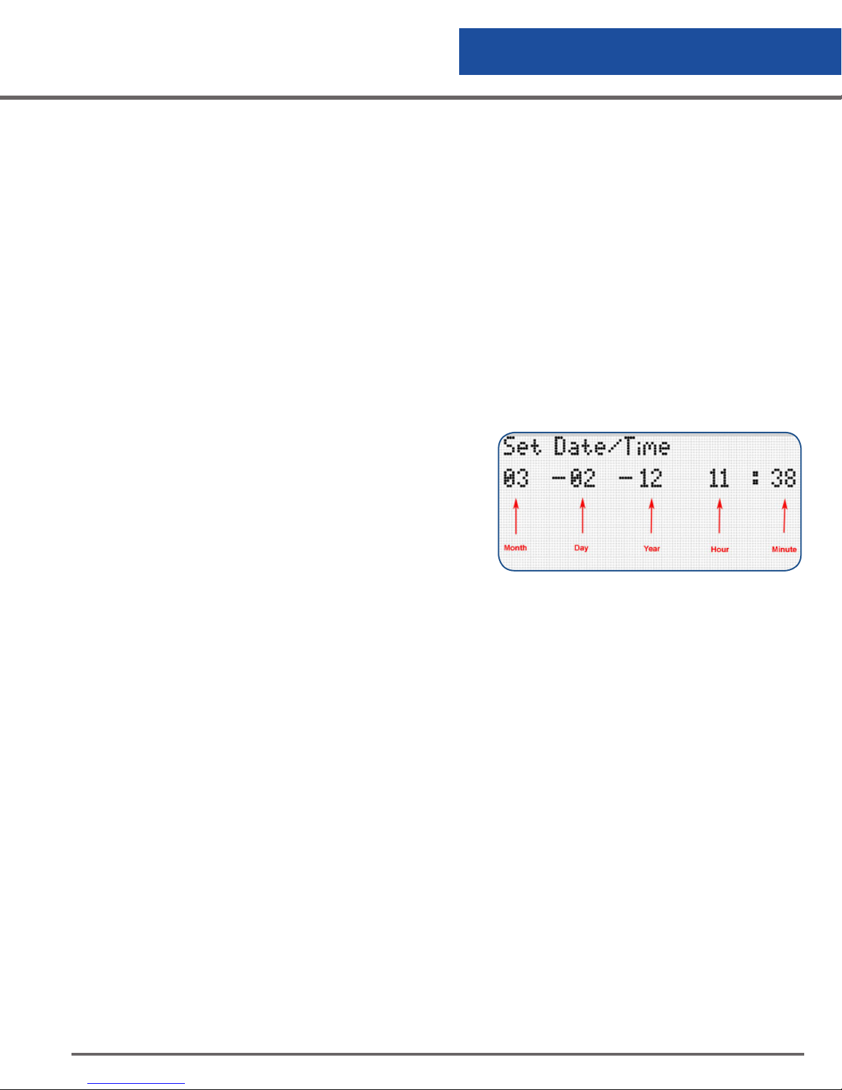
• Date/Time:
• Set Date/Time: Allows the user to set the date
and the time. Use the up/down arrows to
change settings. Use the left/right arrows to
move between the date and time fields.
• Date Format: Allows the user to change
between U.S. and International format.
• Date & Time Sync: This feature can be used to
automatically synchronize the date and time
between the CS200 Control and the ciSmart
Com Communications Hub.
Figure 5.0 Set Date/Time Menu
• Lid Functions
• Lid Switch: Allows the user to enable/disable the lid switch feature.
• Quickchill Timer: Allows the user to set the amount of time that the solenoid valve will stay open
after the lid is closed.
• Manual Defog Timer: Allows the user to set the amount of time that the solenoid valve stays open
when the Fill/Defog button is pressed and the LN2 level is within normal range.
• Auto Defog Timer: Allows the user to set the amount of time that the solenoid valve stays open
when the lid is opened and LN2 level is within the normal range.
• User Access
• User Access On/Off: Allows the user to enable/disable this feature.
• User ID’s: Allows the user to set user identification for freezer access.
• User ID On/Off: Allows the user to turn off user identification.
• Delete user ID: Allows the user to delete user ID’s.
CS200 Control Systems
23
Page 24

Controller Operation
• Lid Safety Interlock: Allows the user to disable the solenoid valve if the lid is open.
• System Alarms
• Test Alarms: Allows the user to manually check the audible, visual and remote alarm.
• LN
Supply Alarm Delay: Allows the user to set the delay before an error condition
2
occurs if the freezer does not fill in a timely manner. If this alarm occurs the supply should be
checked to insure that the supply valve on turned on, a sufficient supply of LN2 is available in the
supply cylinder and the LN2 source pressure is adequate.
Settings [30, 45, 60, 75, 90 min] or [2, 3, 4 hours].
• Remote Alarm Delay: Allows the user to set the time before the remote alarm relay is triggered
after an error condition occurs. Settings [Immediate, 30, 60, 90 min] or [2,3, 4, 6 hours]
• Lid Open Alarm Delay: Allow the user to set the time before an alarm condition occurs if the lid is
opened too long.
• Valve Stuck Alarm: Allow the user to enable/disable this feature.
• Audible Repeat Delay: Allows the user to set the time before the audible alarm is
repeated after an alarm has been acknowledged but an error condition has not been corrected.
Settings [15, 30, 60, 120, 240, 480 min] or [1 day] [Never].
• Usage Alarm: Estimates LN
by time and converting to a daily rate, and requires a minimum of two complete fill cycles.
use in the freezer. This is calculated by dividing the level decrement
2
• Display
• Display Brightness: Allows the user to adjust brightness for the display. Settings [1 to 15]
• Freezer ID: Allows the user to provide a nickname for the freezer.
• Fill Sequence Number: Provides the capability to enable local warm gas bypass on
the freezer. Also provides the cabability to enable freezer filling management to optimize LN2 use.
SCHEDULED EVENTS
• Scheduled Fills
• Set Time: Allows the user to set the day and time for the next filling operation.
• Next Fill: Displays the next scheduled fill.
• Maintenance Reminder: Allows the user or service company to acknowledge a
reminder that preventive maintenance should be performed on the freezer. Contact Worthington
Industries Customer Service for instructions how to reset the reminders.
• Acknowledge Reminder: Acknowledges the maintenance reminder and resets it 12 months into
the future.
• Next Reminder: Displays the next scheduled maintenance reminder.
• LN
Supply Reminder: Allows the CS200 to provide a reminder that the LN2 supply should be
2
checked.
CS200 Control Systems
24
Page 25

Controller Operation
• Set Reminder: Allows the user to set the day which the control will display a reminder to check
the supply of LN2. [Off, Sun, Mon, Tues, Wed, Thurs, Fri, Sat, Daily]
• Acknowledge Reminder: Allows the user to acknowledge that the LN
• Next Reminder: Displays the next scheduled reminder.
• Check Level Reminder: Provides a reminder that the LN
manually checked with a dipstick.
level inside the freezer should be
2
• Set Reminder: Allows the user to set the day which the control will display a reminder to check
the supply of LN2. [Off, Sun, Mon, Tues, Wed, Thurs, Fri, Sat, Daily]
• Acknowledge Reminder: Allows the user to acknowledge that the LN
• Next Reminder: Displays the next scheduled reminder.
Below are the Menu Settings that are available only in the “Change Settings” mode.
SECURITY
• Settings Password: Allows the user to set a password to allow setting changes.
• Power Password: Allows the user to set the password which secures power button operation
• Change Remote Password: Allows the user to change the remote password.
The remote password will be used in the future with new features.
supply has been checked.
2
supply has been checked.
2
CONTACT SUPPORT
• LN
Supplier: User-defined.
2
• Distributor: User-defined.
• Worthington Industries: [email protected] / +1 614-438-7968
• Pacer Digital: [email protected] / +1 317-849-7887
SELECT LANGUAGE: Allows the user to select the desired language.
SYSTEM INFORMATION: Displays the control serial number, the firmware version, the freezer ID and any
options that are enabled.
DATA MANAGEMENT: Allows the user the capability to download operational data.
USAGE: Provides easy access to view the usage data.
CS200 Control Systems
25
Page 26
Controller Operation
Temperature
The temperature in the Cryostorage freezer is measured at the location of the thermocouple. The installation
location is different depending on the model of the freezer but usually the thermocouple is positioned level with
the top storage box. This may mean that temperatures displayed may be slightly warmer than the temperature
experienced by the samples or product stored in the freezer.
Temperature Control
The CS200 SERIES Control System has the capability to control the vapor temperature at the top of the freezer.
The temperature is controlled at the location of thermocouple 1.
To maintain temperature, the CS200 SERIES Control System bubbles nitrogen gas through the pool of LN2 in
the bottom of the freezer. The nitrogen gas evaporates some of the LN2 causing a cooling effect and reducing
the temperature in the freezer. Since a pool of LN2 is important in the process of temperature control, an
adequate level is always maintained by the control systems and the level control always takes precedence over
temperature control. Temperature control will not work if the LN2 level is above the High Level Alarm.
Enabling the temperature control feature will always increase the use of LN2. The increased consumption
will depend on a number of factors including the temperature to be maintained, the range of the controlled
temperature, the ambient temperature, the length of supply hose connected to the freezer and the frequency
which users open the lid or otherwise introduce heat.
Battery Operation
The CS200 SERIES Control System is designed to operate with or without an optional battery backup system if
required. Simply plug the battery into the appropriate connector. The control will recognize that the battery has
been connected and will activate the battery backup mode.
LED Status Wheel
The CS200 SERIES Control System offers an
innovative concept called a status wheel. In normal
operation, the LED’s on the status wheel light to
show a slow rotation of the wheel. If an error
condition occurs, the control will alert the user with
an additional visual alarm from the status wheel.
The rotation can be accelerated, flashed or even
illuminated in the opposite direction.
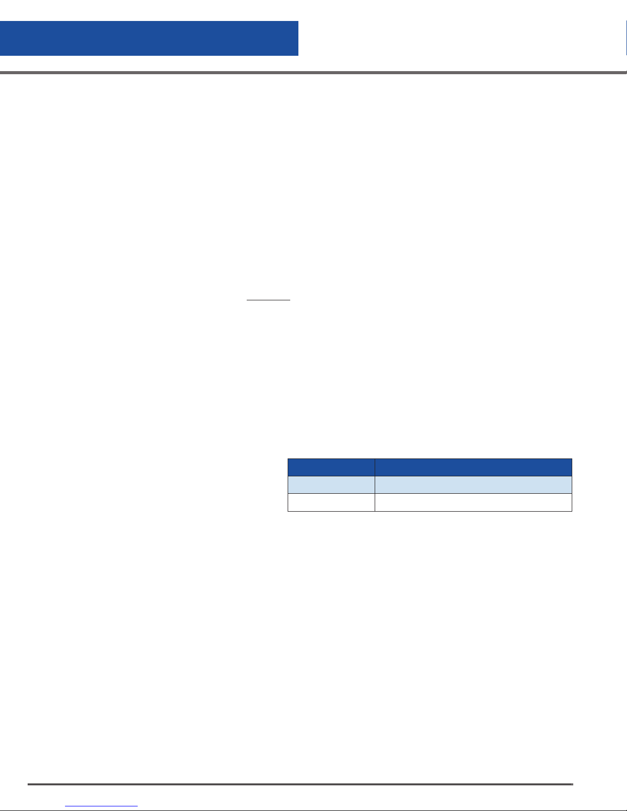
Condition LED Flash Property
Normal Clockwise pattern, 1 LED per second
General Error Clockwise pattern, rapid rotation, flash
Table 4.0 LED Status Wheel Flash Patterns
Lid Switch
The lid switch consists of a magnet and a pickup installed on the lid. The control can determine when the lid
is opened because the magnet moves out of range of the pickup and the circuit becomes open. A number of
features are associated with the lid switch such as Auto Defog, Quickchill and the Lid Open Too Long Alarm. If
the lid switch is deactivated, these features are also disabled.
CS200 Control Systems
26
Page 27
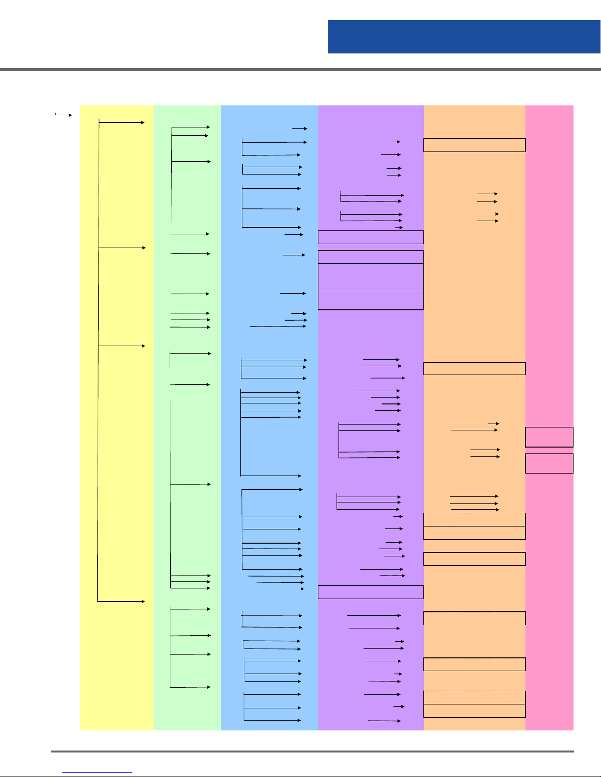
Menu System
MENU
T/C 1 On/Off T/C 2 On/Off
T/C 1 OK/OPEN/Off
T/C 2 OK/OPEN/Off
CELCIUS FAHRENHEIT KELVIN
RANKINE
123456789 LID SWITCH
LLLGGGGGG Open/Closed
Thermistor Status 0:
1: 2: 3: 4:
5: 6: 7: 8:
LLA START STOP HLA
SENSOR OFFSET 0:60 INCH
U.S. INTERNATIONAL US:
MM/DD/YY INTL: DD/MM/YY
USER1
USER3
USER1
USER3
30-45-60-75-90 MIN 2-3-
4 HOURS
IMMEDIATE 30-60-90 MIN 2-3-
4-6 HOURS
15-30-60-120-240-480 MIN 1
DAY NEVER
0-100 LOCAL/NETWORK
SET DAY SET TIME Daily-
Off-Day 00:00-24:00
SET DAY SET TIME Daily-
Off-Day 00:00-24:00
SET DAY SET TIME Daily-
Off-Day 00:00-24:00
Enter Level Measured 0:1250
(in .5" increments)
Controller Operation
VIEW ONLY
HIGH TEMPERATURE ALARM
TEMPERATURE
LEVEL
SYSTEM
SCHEDULED EVENTS
THERMOCOUPLE SELECT
TEST TEMPERATURE SYSTEM
CONTROL BY TEMPERATURE
TEMPERATURE ALARMS
TEMPERATURE UNIT
THERMISTOR STATUS
SENSOR POSITIONS
VALVE OPEN DURATION OPEN 0:120 MIN CLOSE 0:60 MIN
SENSOR ERROR MUTE On/Off
INCH/CM INCH/cm/mm
DATE/TIME
LID FUNCTIONS
SYSTEM ALARMS
DISPLAY DISPLAY BRIGHTNESS 1:15
FREEZER ID FREEZER ID
FILL SEQUENCE NUMBER
SCHEDULED FILLS
MAINTENANCE REMINDER
LN2 SUPPLY REMINDER
CHECK LEVEL REMINDER
CHECK THERMOCOUPLES
TEST TEMP ALARMS Off - High Temp - Low Temp
TEMP CONTROL ON/OFF On/Off
TEMP CONTROL RANGE -170:-105 C -165:-100 C
LOW TEMPERATURE ALARM
TIME WITH NO TEMP ALARM TEMP1: 0 TEMP2:0
Thermistor Status
0: 1: 2:
3: 4: 5:
6: 7: 8:
02 03 06 07
SET DATE/TIME 00 - 00 - 00 00: 00
DATE FORMAT
DATE & TIME SYNC On/Off
LID SWITCH On/Off
QUICKCHILL TIMER 0:300 seconds
MANUAL DEFOG TIMER 0:300 seconds
AUTO DEFOG TIMER 0:300 seconds
USER ACCESS
LID SAFETY INTERLOCK On/Off
TEST ALARMS
LN2 SUPPLY ALARM DELAY
REMOTE ALARM DELAY
LID OPEN ALARM DELAY 1:20 MIN
VALVE STUCK ALARM On/Off
AUDIBLE REPEAT DELAY
USAGE ALARM On/Off CLEAR ALARM
(0 = NO SEQUENCING)
SET TIME
NEXT FILL 00-00-00 00:00
ACKNOWLEDGE REMINDER YES
NEXT REMINDER 00-00-00 00:00
SET REMINDER
ACKNOWLEDGE REMINDER YES
NEXT REMINDER 00-00-00 00:00
SET REMINDER
ACKNOWLEDGE REMINDER
NEXT REMINDER 00-00-00 00:00
THERMOCOUPLE 1 -190:0
THERMOCOUPLE 2 -190:0
THERMOCOUPLE 1 -196:0 On/Off
THERMOCOUPLE 2 -196:0 On/Off
USER ACCESS ON/OFF On/Off
USER IDs
USER ID ON/OFF On/Off
DELETE USER ID
AUDIBLE On/Off
VISUAL On/Off
REMOTE On/Off
30-45-60-75-90 MIN
2-3-4 HOURS
IMMEDIATE 30-60-90 MIN
2-3-4-6 HOURS
15-30-60-120-240-480 MIN
1 DAY NEVER
SET DAY SET TIME
Daily-Off-Day 00:00-24:00
SET DAY SET TIME
Daily-Off-Day 00:00-24:00
SET DAY SET TIME
Daily-Off-Day 00:00-24:00
Enter Level Measured
0:1250 (in .5” increments)
USER2
USER2
Figure 6.0 Menu System - View Only
CS200 Control Systems
27
Page 28
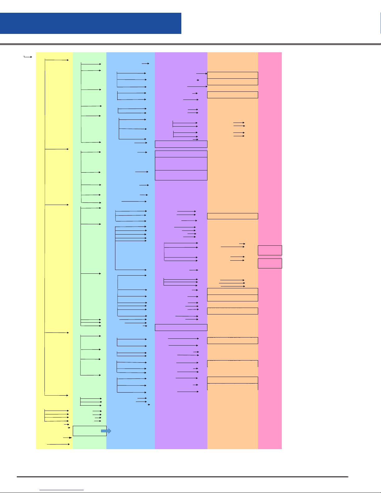
Controller Operation
MENU
T/C 1 On/Off T/C 2 On/Off
PUT T/C 1 IN ICE WATER (0C) PUT
T/C 1 IN LN2 (-196C) DONE!
PUT T/C 2 IN ICE WATER (0C) PUT
T/C 2 IN LN2 (-196C) DONE!
T/C 1 Ok/Off T/C 2
Ok/Off
Off- High Temp 1!- High Temp2!- Low
Temp1!- Low Temp2!
CELCIUS FAHRENHEIT KELVIN
RANKINE
123456789 LID SWITCH
LLLGGGGGG Open/Closed
Thermistor Status
1: 2:
5: 6: 7: 8:
LLA START STOP HLA
02 03 06 07
SENSOR OFFSET 0:60 INCH
U.S. INTERNATIONAL
MM/DD/YY INTL: DD/MM/YY
USER1
USER2
USER3
USER1
USER2
USER3
30-45-60-75-90 MIN 2-3-4
HOURS
IMMEDIATE 30-60-90 MIN
2-3-4-6 HOURS
15-30-60-120-240-480 MIN 1
DAY NEVER
0-100 LOCAL/NETWORK
SET DAY SET TIME Daily-
Off-Day 00:00-24:00
SET DAY SET TIME Daily-
Off-Day 00:00-24:00
SET DAY SET TIME Daily-
Off-Day 00:00-24:00
Enter Level Measured 0:1250
(in .5" increments)
SERIAL # 12345
VERSION 1. 03
FREEZER ID FRZ01
DOWNLOAD LOGS
00-00-00 All Logs-Temp Logs- Alarm
Logs- Temp&Alarm Logs
CHANGE SETTINGS
CONTACT SUPPORT
SELECT LANGUAGE ENGLISH-GERMAN
SYSTEM INFORMATION
DATA MANAGEMENT
USAGE 0.00 IN PER DAY
TEMPERATURE
LEVEL
SYSTEM
SCHEDULED EVENTS
SECURITY
LN2 SUPPLIER CONTACT INFO
DISTRIBUTOR CONTACT INFO
WORTHINGTON
PACER DIGITAL CONTACT INFO
THERMOCOUPLE SELECT
CALIBRATE
TEST TEMPERATURE SYSTEM
CONTROL BY TEMPERATURE
TEMPERATURE ALARMS
TEMPERATURE UNIT
THERMISTOR STATUS
SENSOR POSITIONS
VALVE OPEN DURATION OPEN 0:120 MIN CLOSE 0:60 MIN
SENSOR ERROR MUTE On/Off
INCH/CM INCH/cm/mm
DATE/TIME
LID FUNCTIONS
SYSTEM ALARMS
DISPLAY DISPLAY BRIGHTNESS 1-15
FREEZER ID FREEZERID
FILL SEQUENCE NUMBER
SCHEDULED FILLS
MAINTENANCE REMINDER
LN2 SUPPLY REMINDER
CHECK LEVEL REMINDER
SETTINGS PASSWORD 0 0 0 0
POWER PASSWORD 0 0 0 0
CHANGE REMOTE PASSWORD 0 0 0 0
CONTACT INFO
Options
CALIBRATE THERMOCOUPLE 1
CALIBRATE THERMOCOUPLE 2
RESTORE CALIBRATION ABORT/LOAD
CHECK THERMOCOUPLES
TEST TEMP ALARMS
TEMP CONTROL ON/OFF On/Off
TEMP CONTROL RANGE -170:-105 C -165:-100 C
HIGH TEMPERATURE ALARM
LOW TEMPERATURE ALARM
TIME WITH NO TEMP ALARM TEMP1: 0 TEMP2:0
Thermistor Status
0: 1: 2:
3: 4: 5:
6: 7: 8:
SET DATE/TIME 00 - 00 - 00 00: 00
DATE FORMAT
DATE & TIME SYNC On/Off
LID SWITCH On/Off
QUICKCHILL TIMER 0:300 seconds
MANUAL DEFOG TIMER 0:300 seconds
AUTO DEFOG TIMER 0:300 seconds
USER ACCESS
LID SAFETY INTERLOCK On/Off
TEST ALARMS
LN2 SUPPLY ALARM DELAY
REMOTE ALARM DELAY
LID OPEN ALARM DELAY 1:20 MIN
VALVE STUCK ALARM On/Off
AUDIBLE REPEAT DELAY
USAGE ALARM On/Off CLEAR ALARM
(0 = NO SEQUENCING)
SET TIME
NEXT FILL 00-00-00 00:00
ACKNOWLEDGE REMINDER YES
NEXT REMINDER 00-00-00 00:00
SET REMINDER
ACKNOWLEDGE REMINDER YES
NEXT REMINDER 00-00-00 00:00
SET REMINDER
ACKNOWLEDGE REMINDER
NEXT REMINDER 00-00-00 00:00
THERMOCOUPLE 1 -190:0
THERMOCOUPLE 2 -190:0
THERMOCOUPLE 1 -196:0 On/Off
THERMOCOUPLE 2 -196:0 On/Off
0:
3: 4:
USER ACCESS ON/OFF On/Off
USER IDs
USER ID ON/OFF On/Off
DELETE USER ID
AUDIBLE On/Off
VISUAL On/Off
REMOTE On/Off
30-45-60-75-90 MIN
2-3-4 HOURS
15-30-60-120-240-480 MIN
1 DAY NEVER
SET DAY SET TIME
Daily-Off-Day 00:00-24:00
SET DAY SET TIME
Daily-Off-Day 00:00-24:00
SET DAY SET TIME
Daily-Off-Day 00:00-24:00
Enter Level Measured
0:1250 (in .5” increments)
US:
Figure 6.1 Menu System - Change Settings
CS200 Control Systems
28
Page 29
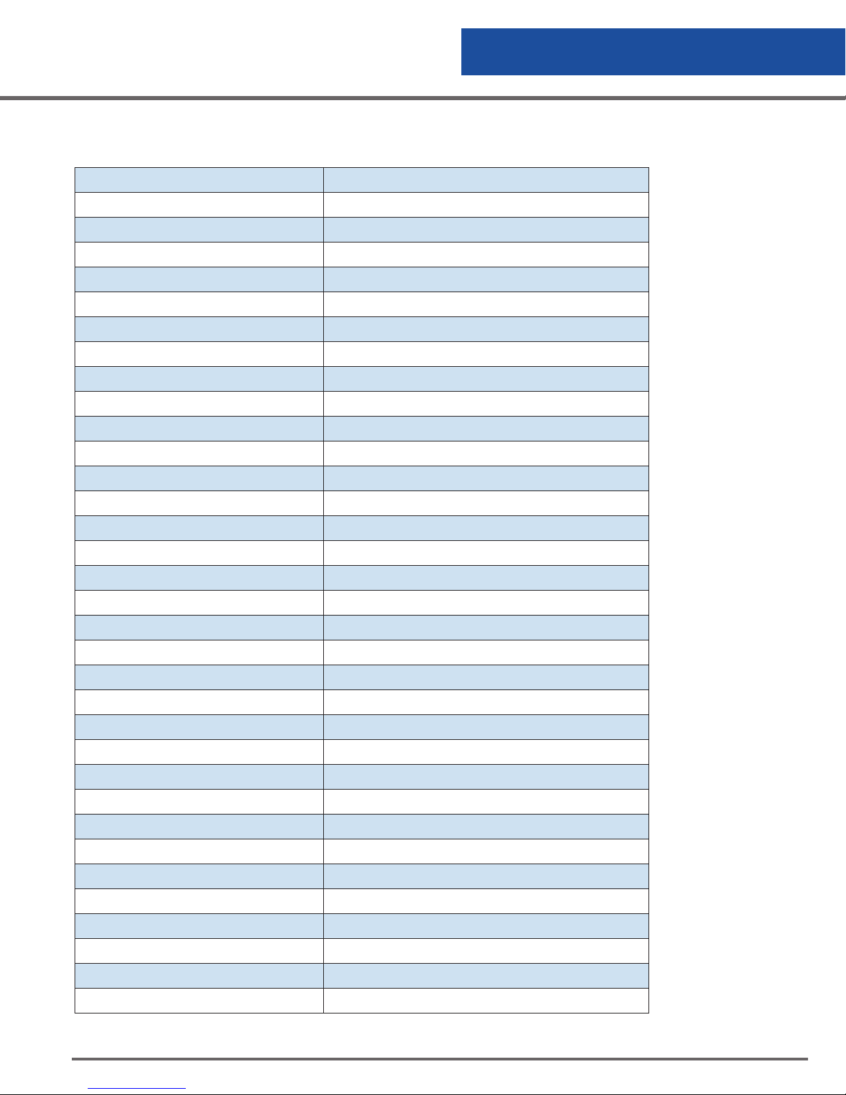
Factory Defaults
Thermocouple #1 On
Thermocouple #2 Off
Control by Temperature Off
High Temperature Alarm #1 -100°C
High Temperature Alarm #2 -100°C
Low Temperature Alarm #1 Off
Low Temperature Alarm #2 Off
Temperature Units Celsius
Sensor Position Freezer dependant
Valve Open Duration Off
Sensor Type 8-thermistor sensor (standard)
Freezeguard feature On
Controller Operation
Sensor Error Mute Off
Freezeguard Error Mute Off
Level Units of Measure inch
Date/Time Factory Set for Central Standard Time
Lid Switch On
Quickchill Timer 30 seconds
Manual Defog Timer 30 seconds
Auto Defog Timer 30 seconds
User Access Off
Lid Open-Valve Off Off
LN2 Supply Alarm Delay 30 minutes
Remote Alarm Delay 30 minutes
Lid Open Alarm Delay 10 minutes
Valve Stuck Alarm On
Audible Retrigger 30 minutes
Display Brightness 10
Screen Saver Time 30 minutes
Freezer ID Not set
Scheduled Fills Off
LN2 Supply Reminder Off
Settings Password Off
Power Password Off
Table 5.0 Factory Defaults
CS200 Control Systems
29
Page 30
Controller Operation
Troubleshooting
If the Worthington Industries Cryostorage freezer with the CS200 SERIES Control System installed experiences
problems or appears that it is not operating at optimum efficiency, please contact your distributor for
assistance. The CS200 SERIES Control System has incorporated state of the art diagnostic tools to assist in the
identification and correction of any issues that may arise.
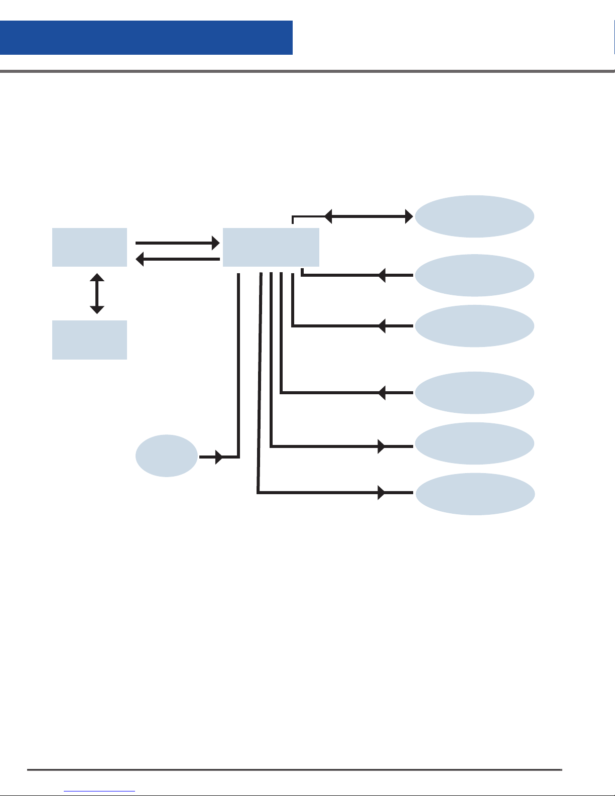
Interconnection Block Diagram
Cable with
Firewire
connectors
Control
Display
40 pin connector
Thermocouple
Connector (2)
Lid Switch
Harness Assembly
& Junction Box
CryoWire Secure
(Communications)
Power Supply
(12 Volt DC)
Level Sensor
Assembly
Thermocouple
Assembly
(Temperature)
Solenoid Valve
Remote Alarm
(Dry contact relay)
TM
(3)
Figure 7.0 Interconnection Block Diagram
CS200 Control Systems
30
Page 31
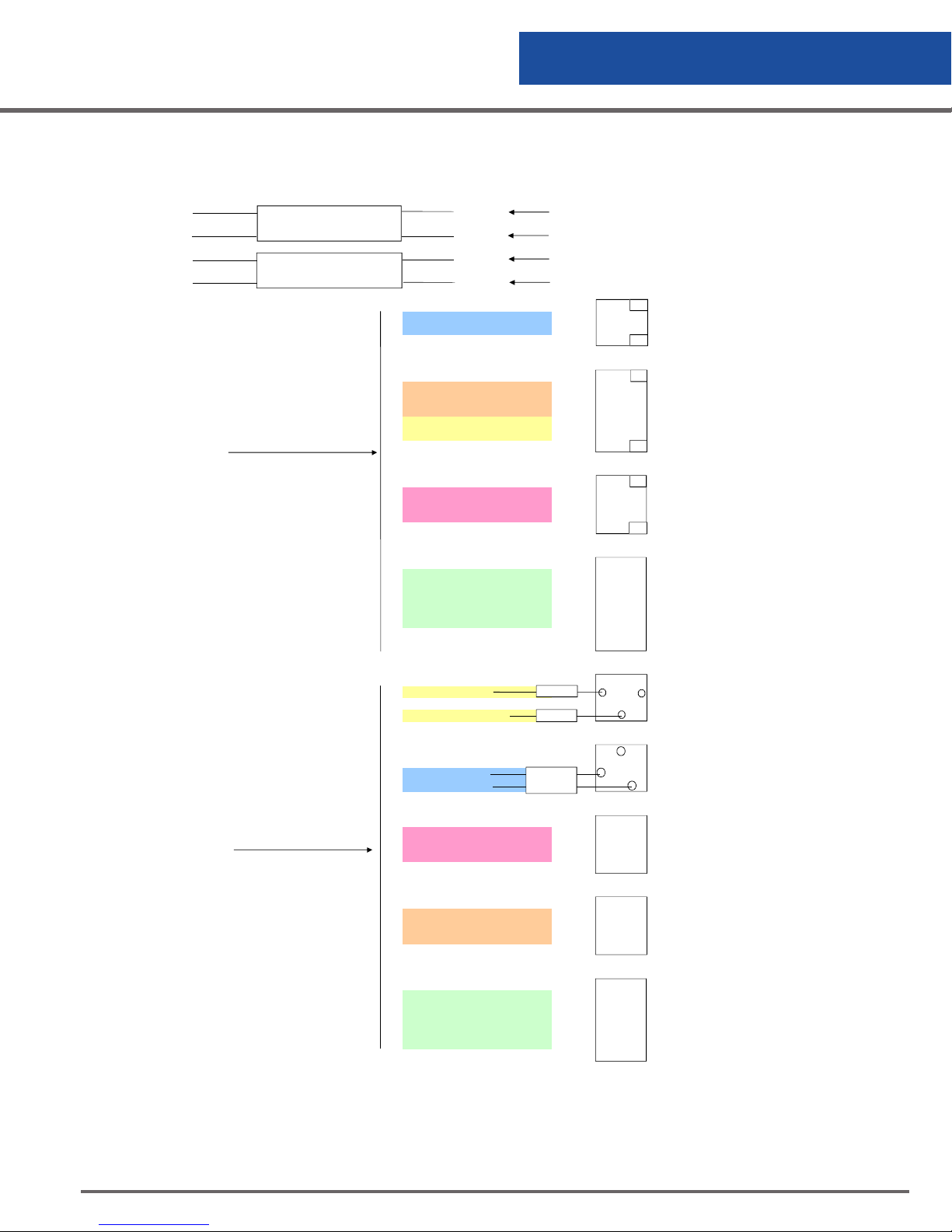
Wiring Diagram
CS200 Harness Wiring Diagram
Controller Operation
4 wires position 1 P1P1
4 wires position 2 P1P2
10 wires position 1 P2P1
10 wires position 2 P2P2
Harness Control End
Pod 1
Pod 2
Blue P1P1 Battery
Red P1P1
Yellow + White/Yellow P2P1 Remote Alarm
Orange + White/Orange P2P1 Remote Alarm
Brown + White/Brown P2P1 Remote Alarm
Yellow/Green P1P1 Power
White P1P1 Power
White/Black P2P1
Red + Black P2P1 RS-232
White/Red P2P1
Black P2P2
Brown P2P2
Red P2P2 Sensor
Orange P2P2
Yellow P2P2
P2P2
2
1
5
4
3
2
1
3
2
1
6
5
4
3
2
1
white Power Connector
White
Yellow/Green
Red
Blue
Connector Box End White/Red P2P1
White/Black P2P1 DB-9 Connector
Red + Black P2P1
White/Yellow + Yellow P2P1
White/Orange + Orange P2P1 Remote Alarm Connector
White/Brown + Brown P2P1
Black P2P2
Brown P2P2
Red P2P2 Sensor Assembly
Orange P2P2
Yellow P2P2
P1P1
P1P1
P1P1
P1P1
2
3
5
1
2
3
1
2
3
4
5
Figure 8.0 CS200 Series Control System Harness Wiring Diagram
Valve Connector
CS200 Control Systems
31
Page 32
Controller Operation
Intallation & Set-up
The CS200 CONTROL SYSTEM consists of the following components:
• Main Control
• VFD Display Module
• Wiring Harness Assembly
• Power Supply
• Thermocouple Assembly
• Lid Switch Assembly
• Sensor Assembly
• Cryogenic Solenoid Valve
• Remote Alarm Plug
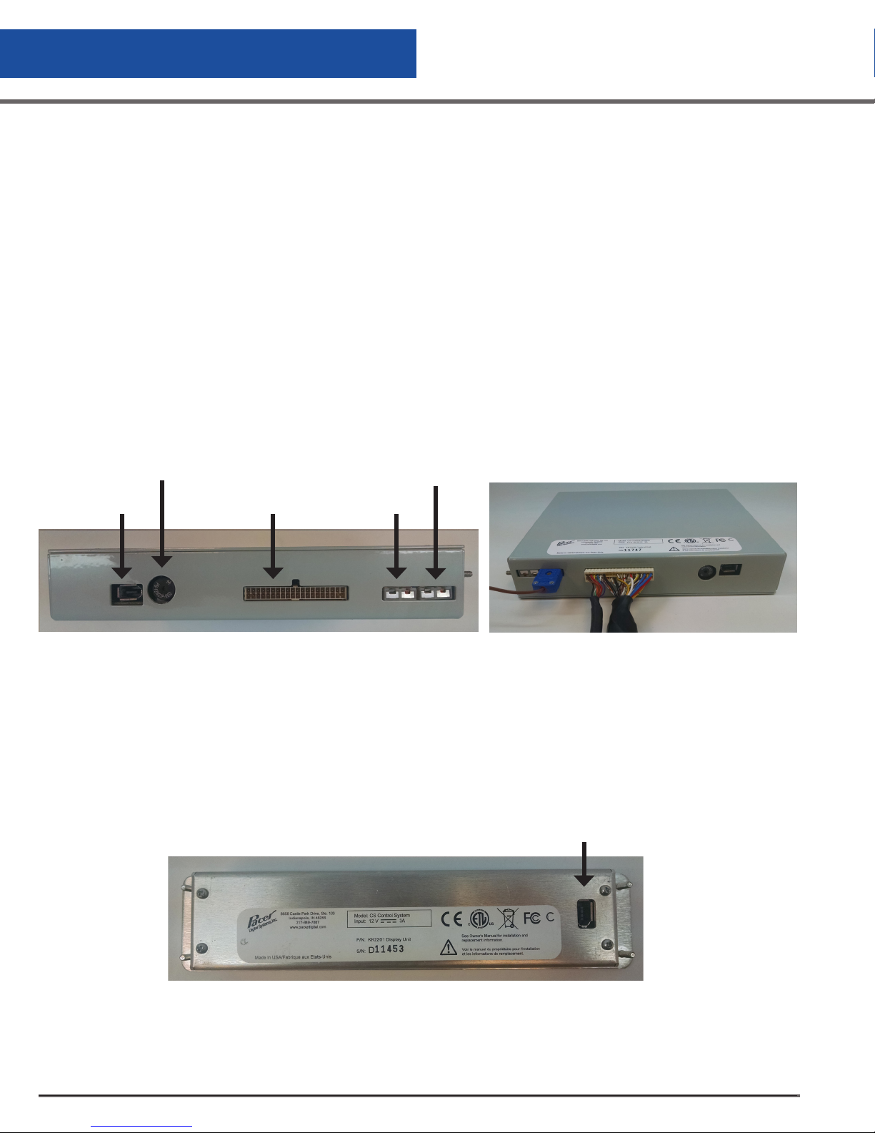
Connect the wiring harness assembly to the main control. The connector is keyed and can only be plugged in
one way.
Speaker
Display
Connector
Connect the thermocouple plug of the harness assembly into the control at the thermocouple plug labeled
T/C #1. One of the blades on the plug is slightly wider insuring that it is plugged in correctly. The copper blade
should plug into copper-colored plug. Finally, connect the display cable into the main control and the display.
Main Harness
Connector
Figure 9.0 Main Control Back Panel
T/C #2
T/C #1
Connection to Main Control
Figure 10.0 Connection to Main Control
CS200 Control Systems
32
Page 33
Controller Operation
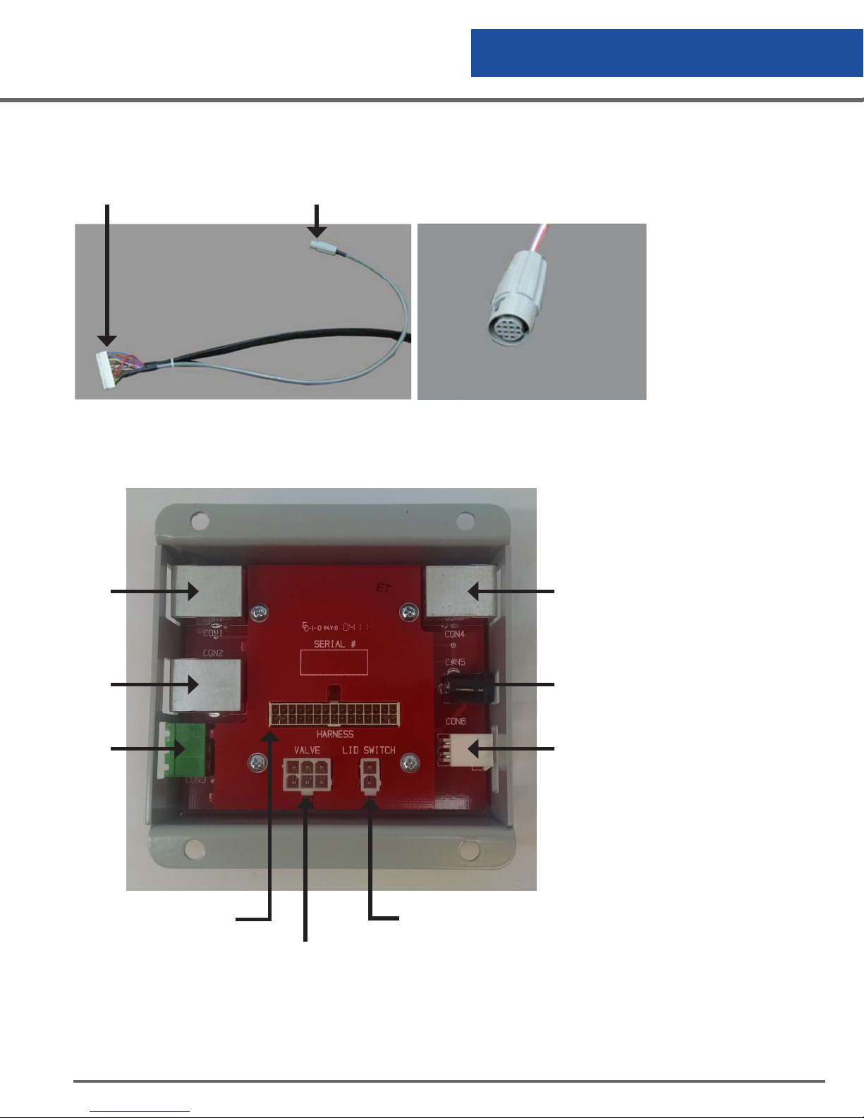
Connect the level sensor assembly into the pigtail with the round connector terminating at the control end of the
harness assembly. The connector is a round locking connector that is keyed so it can only be plugged in one
way.
Connector to Main Control Connector for Level Sensor
Cryowire
Port
Cryowire
Port
Remote
Alarm
Figure 11.0 Harness Assembly
Figure 11.1 Sensor
Assembly Connector
Cryowire
Port
Power
Battery
Connect the solenoid valve
and the lid switch into the
appropriate connectors on
the connector box. These are
located on the circuit board
inside the box and are labeled. The solenoid connector
is a 6-pin locking connector
and the lid switch is a 2-pin
locking connector. Each is
keyed so they can only be
plugged in one way.
Harness Connector to
Main Control
Valve and Freeze Guard
Sensor Connector
Figure 12.0 Harness Assembly & Back Panel
Lid Switch
Connector
CS200 Control Systems
33
Page 34
Controller Operation
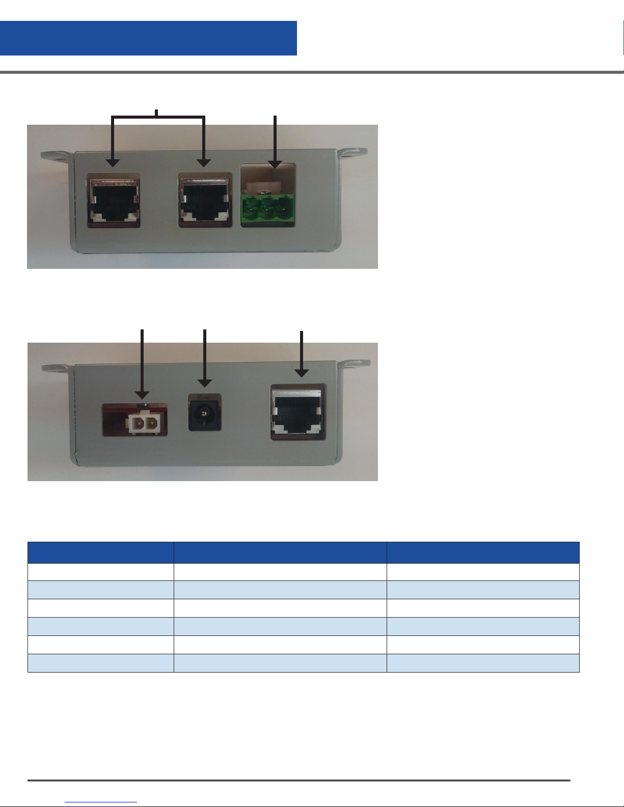
Cryowire Dual
Communication Ports
Figure 13.0
Remote Alarm Connector
Connect the Remote Alarm plug into
the panel at the end of the wiring
harness assembly. It is keyed so that
it can only be plugged in one way.
Battery
Connector
Power
Connector
Cryowire
Communication Port
Finally, connect the barrel plug of
the power supply and the battery
into the appropriate receptacles in
the connector box.
Figure 14.0
External Connector Ratings
Designated Use Max rated voltage/current ratings Connector type
Power 36 VDC 2.5mm barrel connector
CryoWire Secure™ N/A Modular shielded jack
Remote Alarm 300 volts 5mm terminal block
Solenoid Valve 600 volts 4.2mm header
Thermocouple N/A 2-pin thermocouple
Level Sensor 5 amps / contact Sealed circular connector
Table 6.0 External Connector Ratings
CS200 Control Systems
34
Page 35
Controller Operation
LED Status Wheel Flash Patterns
Condition LED Flash Property
Normal Clockwise pattern, 1 LED per second
General Error Clockwise pattern, rapid rotation, flash
Table 7.0 LED Status Wheel Flash Patterns
Temperature Thermocouple Select
The chamber temperature is monitored with 1 or 2 Type T thermocouples. The thermocouple is placed in the
chamber to monitor temperature level at the top of the inventory system. Factory installation includes one
thermocouple inside the thermocouple tube at an elevation to match the height of standard racks. A second
Type T thermocouple may be added to monitor another location inside the chamber. Both thermocouples can
be activated/deactivated through the menu system.
Temperature Calibration
The CS200 CONTROL SYSTEM uses a Type T thermocouple to measure temperature within the Cryostorage
freezer. The temperature curve for a thermocouple is nonlinear so it is important that the CS200 CONTROL
SYSTEM have a good calibration to provide accurate temperature readings. The temperature is traceable to the
National Institute of Standards and Technology (NIST) ITS-90 Thermocouple Database.
There are three important reference points needed for calibration:
• Ambient Temperature: Room Temperature
• Ice Water: 0°C
• Liquid Nitrogen (LN2): -196°C (-320°F)
The ambient temperature is the temperature measured inside the control box and is used to
provide temperature compensation adjustment. This is calibrated at the factory and should
not be adjusted in the field.
Ice water and LN2 provide the reference points on the temperature curve. If these two points are
calibrated correctly then all other points (temperatures) on the curve are correct.
The accuracy of a thermocouple is +/- 1°C or +/- 1.5% of the reading, whichever is greater.
To check a calibration, dip the thermocouple in ice water and then LN2. If readings are within
accuracy specifications noted above, the temperature circuit on the control is properly
calibrated. If not, follow the steps below to calibrate the temperature.
CS200 Control Systems
35
Page 36
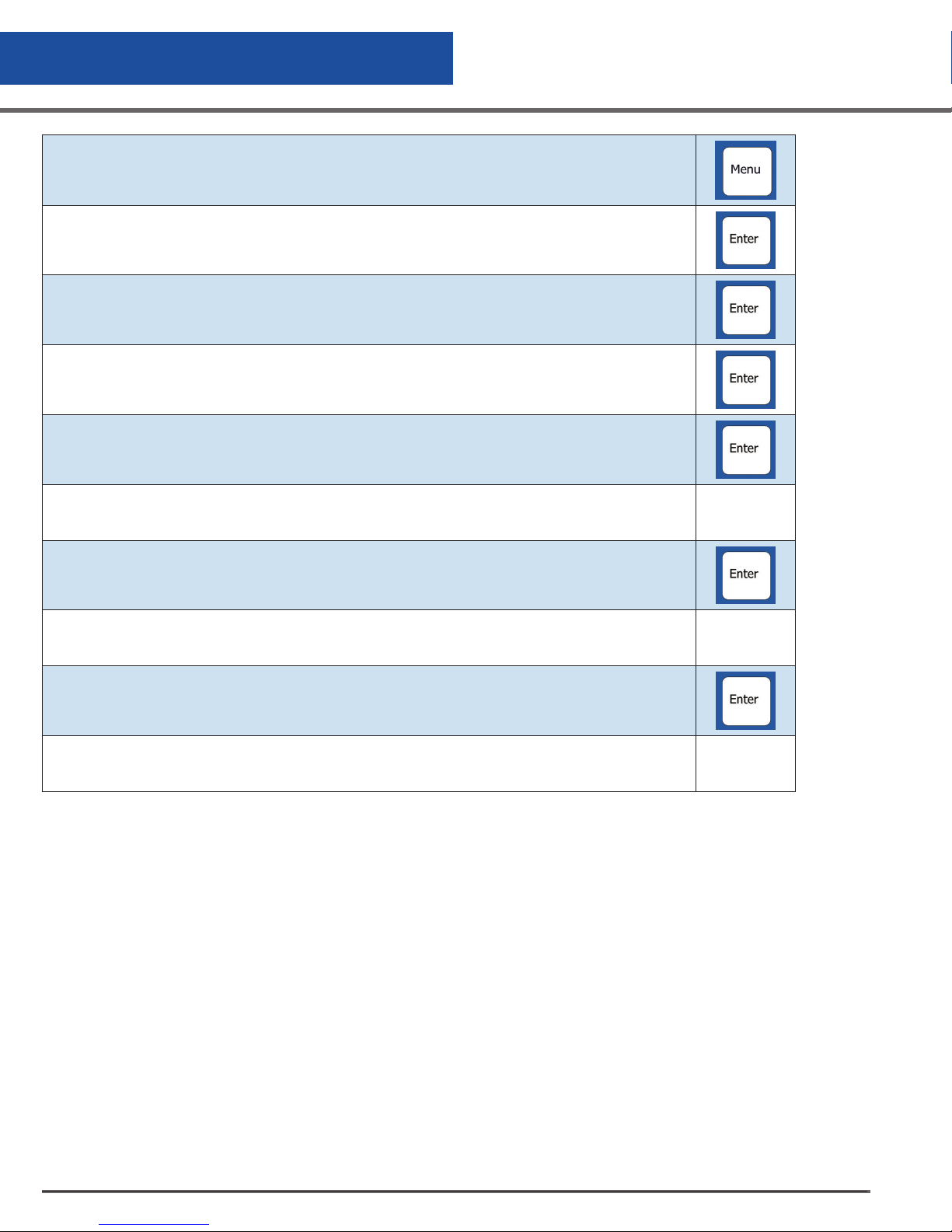
Controller Operation
Access the menu by pressing
Highlight CHANGE SETTINGS and press
Highlight TEMPERATURE and press
Highlight CALIBRATE and press
Highlight CALIBRATE THERMOCOUPLE 1.
The display will read Dip the thermocouple into ice water.
Submerge the thermocouple into an ice water bath. The bar graph will fluctuate. When a good
stable reading in obtained, the bar graph will decrease to 1 or 2 bars. At this point, press to
lock in the value. Dry the thermocouple.
The display will read Dip the thermocouple into LN2.
Submerge the thermocouple into LN2. The bar graph will fluctuate. When a good stable reading in obtained, the bar graph will decrease to 1 or 2 bars. At this point, press to lock in the
value
If the calibration values fall within the expected range, “DONE!” Will be displayed on the
screen.
Table 8.0 Temperature Calibration Instruction
Test Temperature System
The temperature circuitry can be checked at any time through the menu system. This check will tell if the
thermocouples are working or if they are “open” (broken or unplugged). If a thermocouple is not connected to
the control it will check as “open.” If a thermocouple is “Disabled” through the menu system, it will not show up
on the check.
Test Level Sensors
The sensor assembly can be tested through the menu system. The sensor diagnostics indicates the sensor
number and the status (whether in liquid or gas). If the control is set for an eight-thermistor it will indicate 9
sensors in the diagnostics. The status is indicated with either an “O” for open, a “G” for gas or an “L” for
liquid. This is an easy means to tell if sensors are in or out of liquid or if a new sensor assembly is needed
(open or defective sensors).
If the sensor assembly is unplugged and the main control is still on, the display will indicate that a sensor error
CS200 Control Systems
36
Page 37

Controller Operation
has occurred. This occurs because the control cannot differentiate between a very high resistance (when a
thermistor is in LN2) and an infinite resistance (when an open circuit appears in the level sensing circuitry).
Alarms and Error Conditions
The CS200 SERIES Control System control monitors many different conditions in the freezer and has a full
complement of alarms associated with these different conditions. As alarms occur, they trigger an audible tone
as well as a flashing red light on the status wheel. A remote alarm relay is also triggered following a userdesignated period of time, after the error condition occurs, if it is not corrected. In addition, the error condition
is displayed on the top line of display until the error condition is corrected. When an error occurs, the audible
alarm may be muted by pressing the designated button. The audible alarm will then be silent until activated
by a new error condition or the alarm is not corrected by the time the retrigger timer expires. A red light will
continue to flash until all errors are corrected. The remote alarm will be activated if the power is interrupted.
The High Temperature Alarm for Thermocouple #1 can be set through the menu system. This alarm is activated if
the temperature rises above the designated temperature. The alarm temperature can range from 0°C (32°F) to
-196°C (-320°F). It can also be disabled.
High Temperature Alarm for Thermocouple #2 can be set through the menu system. This alarm is activated if
the temperature rises above the designated temperature. The alarm temperature can range from 0°C (32°F) to
-196°C (-320°F). It can also be disabled.
System Alarms
A Low LN2 Supply Alarm can be set through the menu system. This alarm is activated if the solenoid valve is not
closed within a designated time period after a fill starts. The solenoid valve can be closed either automatically
(the LN2 level reaches the STOP FILL sensor) or manually (the Stop Fill button is pressed). To change the timer
which activates this alarm, the menu options for this alarm are None, 15, 30, 45, 60 minutes, 2 or 3 hours.
This alarm does not correct itself until the fill is stopped (the solenoid closes).
The Sensor Error Alarm can be set through the menu system. This alarm is activated if the control detects a
sensor error. The possible choices are ENABLE or DISABLE. An open sensor can be confirmed through the TEST
LEVEL SENSORS option in the menu system.
A Remote Alarm Timer can be set through the menu system. This is the amount of time before the remote alarm
relay is triggered if an error condition is not corrected. The possible choices are None, Immediate, 30 minutes,
60 minutes or 2 hours.
Lid Open Too Long Alarm can be set through the menu system. This is the amount of time the lid can be open
before it triggers an alarm condition. The possible choices are None, 1, 2, 5 or 10 minutes.
Thermocouple Alarm can be set through the menu system. This alarm is activated if either thermocouple
experiences an open circuit. Your choices are ENABLE or DISABLE.
Test Alarms
Audible, visual and remote alarms can be tested at any time through the menu system. Follow the instructions
on the display to hear the audible indicator of an alarm, to see the red status wheel flash or to trigger an
immediate remote alarm.
Logging
On-board memory logging is one of the most powerful and useful features of the CS200 SERIES Control
System. It provides a historical record for the freezer and a complete record of the environment in which
specimens are stored.
CS200 Control Systems
37
Page 38
Controller Operation
1. System Log: System logs are events that occur in the system including lid opening/closing, LN2 filling, QuickChill and Defog.
2. Error Log: Error logs are outside the activated preset limits detected by the system.
3. Temperature #1 Log and Temperature #2 Log (for use with optional thermocouple #2): The two temperature
logs are simply records of the temperatures recorded by the thermocouples in the system.
All logs are kept in a non-volatile memory, meaning that the information is saved regardless of whether the
controller has power.
Display Brightness
DISPLAY BRIGHTNESS changes the intensity of the display. The default setting is 10.
Making Adjustments to the CS200 SERIES Control System Sensor Assembly
CRYOSTORAGE SYSTEM LOW LEVEL ALARM START FILL STOP FILL HIGH LEVEL ALARM
LABS
20K, 38K, 40K, 80K
LABS 94K
K Series
10K, 24K, 38K
Table 9.0: CS200 SERIES Control System Sensor Assembly Factory Settings
The sensor assembly is preset at the factory for vapor phase storage. If adjustments need to be made, the
following procedure will simplify the process.
The CS200 SERIES Control System control installed on the Worthington Industries Cryostorage units operates
with specially designed software to match the design characteristics of your freezer. Refer to the chart below to
see the versions and their difference.
To make adjustments to a sensor assembly in a freezer filled with LN2, the following procedure can be used:
• Measure the LN2 in the freezer.
• Take this measured level and subtract the offset to determine how many sensors should be in
liquid.
a. Remove sensors.
b. Fill to correct level and turn off Liquid supply.
2 in. (50 mm) 3 in. (76 mm) 5 in. (127 mm)
(at carousel)
5 in. (127 mm) 6 in. (152 mm)
2 in. (50 mm) 3 in. (76 mm)
9 in. (228 mm)
(at carousel)
6 in. (152 mm) 6 in. (152 mm)
6 in. (152 mm)
10 in. (254 mm)
c. Eg. Level is to be 15 in. (381 mm) and sensor number 6 is currently and will remain the Stop
Fill. 15 in. (381 mm) – 6 in. (152 mm) = 9 in. (228 mm) offset. Set Offset to 9 in (228 mm).
• Go to “Test Level Sensor” through the CS200 SERIES Control System menu. “L” means a sensor is
in liquid and “G” means a sensor is in gas.
• Move the sensor up or down so that the appropriate numbers of sensors are in liquid (read “L”).
• Return to the CS200 SERIES Control System main screen and the level indicated should match the
physically measured reading.
The Sensor Offset, the START FILL and the STOP FILL can be set through the CS200 SERIES Control System menu
system.
CS200 Control Systems
38
Page 39
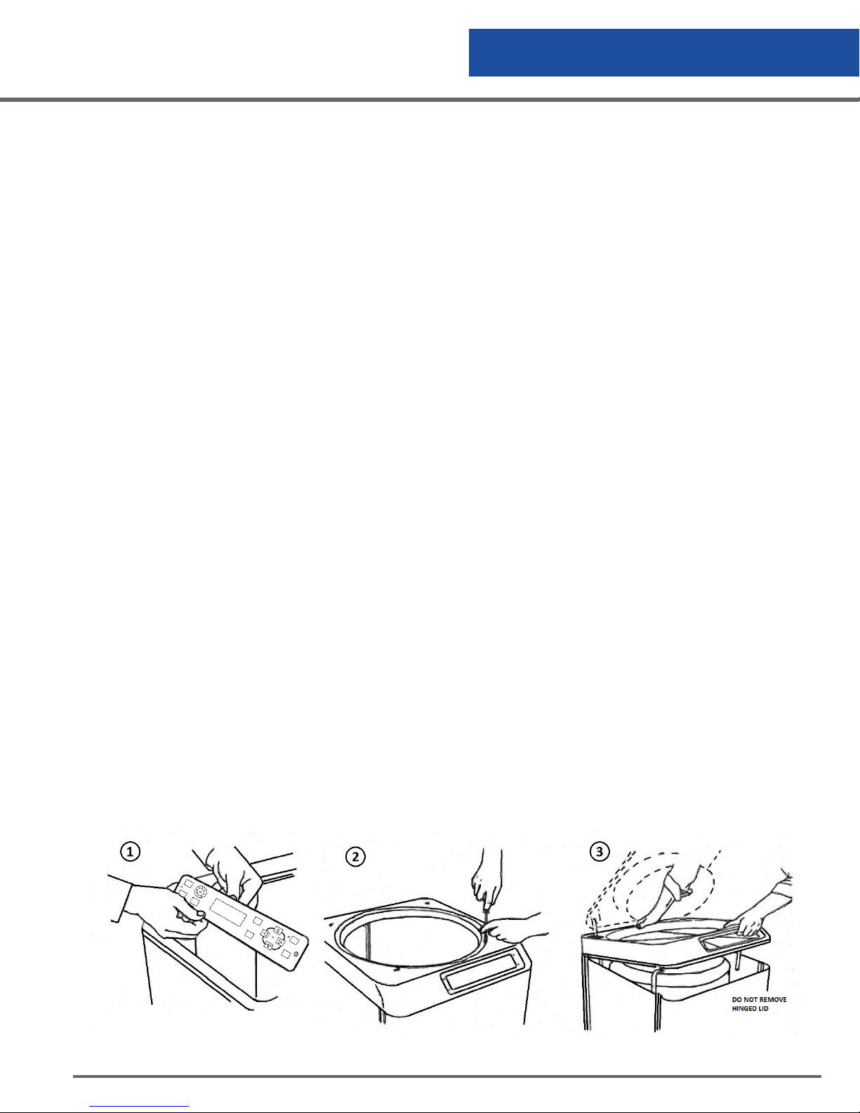
Controller Operation
Removing/Installing the Solenoid Valve
The LN2 and power must be turned off before beginning work on the solenoid valve.
For LABS Electrical Units
Disconnect the solenoid valve lead connection from the back of controller board.
To remove the solenoid valve, loosen the compression fitting that connects the plumbing tubing to the fill tube.
Remove the two (2) mounting screws that hold the solenoid valve to the solenoid bracket. Remove the solenoid
valve and its associated plumbing. Disconnect the plumbing from the inlet and outlet side of the solenoid valve.
To install a new solenoid valve, attach the compression fitting to the fill tube then connect the compression fitting
to the elbow connected to the outlet side of the solenoid valve. Use Teflon tape (three wraps) on all threaded.
Attach the compression fitting to the fill tube first and then connect the compression fitting to the elbow that is
connected to the outlet side of the solenoid valve. Position the solenoid valve onto the solenoid valve bracket
and reattach and tighten the two (2) mounting screws. Attach the solenoid valve lead connection to the
controller board.
Removing/Installing the Controller 10K/24K Units
Remove the cabinet top, follow the steps illustrated in Figure 17. Remove two (2) screws from the display and
lift it from the refrigerator far enough to detach its electrical connection wiring. Remove four (4) screws from the
top of the refrigerator and lift the cabinet top to gain access to the area between the cabinet and the insulated
inner vessel. On the 10K and 24K, the cabinet top may only be raised as shown because of the lid hinges.
Do not remove the hinged lid. After the cabinet top is loosened and propped up, the electrical
connection wiring may be detached to allow access to its back panel connection. At the completion of
maintenance or repairs, reattach the electrical connection wiring from the controller to the display.
Ice or frost in the sensor tube may restrict the movement of sensor probes in the tube. Do not pull excessively on
the sensor wiring while attempting to remove sensors. It may be necessary to remove the sensor tube from the
container and allowed it to thaw before the sensors can be removed.
To install the controller, install the electrical supply connections panel to the back of the refrigerator. Feed
the wiring harness from the electrical supply connections panel to the front of the refrigerator and through
the opening to where the display will be mounted. Attach the electrical supply connections to the controller
board. Be sure to follow all of the installation procedures for the thermocouple, sensor probes and solenoid
valve before you reattach the cabinet top. Reattach the cabinet top with the (4) four screws that were removed
(See Item 2 of Figure 16.0) out to remove the cabinet top. Carefully lower the display into the cabinet. Attach
the display to the cabinet top with the (2) two supplied screws. Be sure that all of the necessary installation
procedures have been completed before you start to fill the refrigerator. To start filling, refer to Filling the
Refrigerator (Initial Fill) section of this manual.
Figure 15.0 K Series Controller Removal
CS200 Control Systems
39
Page 40

Controller Operation
Removing/Installing the Thermocouple
Remove the controller using the procedures outlined for your particular refrigerator model in Removing the
Controller section. Disconnect only the thermocouple lead connection from the controller board. Gently pull the
thermocouple from the sensor tube.
To install a thermocouple, feed the thermocouple lead into the sensor tube to the elevation in the storage
chamber you want to monitor. Connect the thermocouple to the controller board. At the completion of
maintenance or repairs, install the display using the procedure outlined for your refrigerator model in the
Removing/Installing the Controller section.
Removing/Installing the Sensor Probes
Remove the controller using the procedures outlined for your particular refrigerator model in Removing/
Installing the Controller section. Disconnect the sensor probe lead connection from the controller board.
Carefully remove the sensor tube plug from the sensor tube and remove the sensor leads from the plug.
Making Adjustments to the Level Settings
The factory settings for the CS200 control system are as follows:
• Low Level Alarm = 2 (Always 1” below the start fill)
• Start Fill Sensor = 3
• Stop Fill Sensor = 6
• High Level Alarm = 7 (Always 1” above the stop fill)
The sensor assembly is pushed to the bottom of the refrigerator as delivered from the factory. If adjustments
need to be made, the following procedure will simplify the process.
• Determine the range of LN2 level in the refrigerator (i.e. Start Fill = 9; Stop Fill = 12) Offset will be 2.
• Determine the appropriate offset by subtracting 2 from the Start Fill. (i.e. Offset =9 –2 = 7)
• Set the sensor assembly so that the very bottom of the assembly matches the desired offset.
This can be done as follows:
• Push the sensor down the sensor tube until it touches the bottom of the refrigerator.
• Mark the sensor wire where it emerges from the top of the sensor tube.
• Using the marked wire as a reference, pull the sensor up the same distance as the offset setting.
The sensor assembly is now in the correct location.
CS200 Control Systems
40
Page 41

Controller Operation
To make adjustments to a sensor assembly in a refrigerator filled with LN2, the following procedure can be
used:
• Measure the LN2 liquid level in the refrigerator.
• Take this measured level and subtract the offset to determine how many sensors should be in liquid.
• Select MENU, Change Settings, Level, Thermistor Status. “L” means a sensor is in liquid while “G” means
a sensor is in gas.
• Move the sensor up or down so that the appropriate numbers of sensors are in liquid “L”.
• Get back to the Thermistor status screen and the level indicated should match the physically measured
reading. The Sensor Offset, the Start Fill and the Stop Fill can all be set through the MENU, Change
Settings, Level, Sensor Position.
Removing/Installing the Solenoid Valve
Remove the controller using the procedures outlined for your particular refrigerator model in the Removing/
Installing the Controller section. Disconnect only the solenoid valve lead connection from the controller board.
Remove the back plumbing cover of the refrigerator to gain access to the plumbing and solenoid valve.
To remove the solenoid valve loosen the compression fitting that connects the plumbing tubing to fill tube.
Unscrew the two (2) mounting screws that hold the solenoid valve to the solenoid bracket. Then remove the
solenoid valve and its associated plumbing. Disconnect the plumbing from the inlet and outlet side of the
solenoid valve.
To install a new solenoid valve, attach the connecting plumbing to the inlet and outlet connections of the valve
using Teflon tape. Attach the compression fitting to the fill tube first and then connect the compression fitting to
the elbow that is connected to the outlet side of the solenoid valve. Position the solenoid valve onto the solenoid
valve bracket and tighten the two (2) mounting screws. Attach the solenoid valve lead connection to the
controller board. At the completion of maintenance or repairs, install the controller using the procedure outlined
for your refrigerator model in the Removing/Installing the Controller section.
CS200 Control Systems
41
Page 42
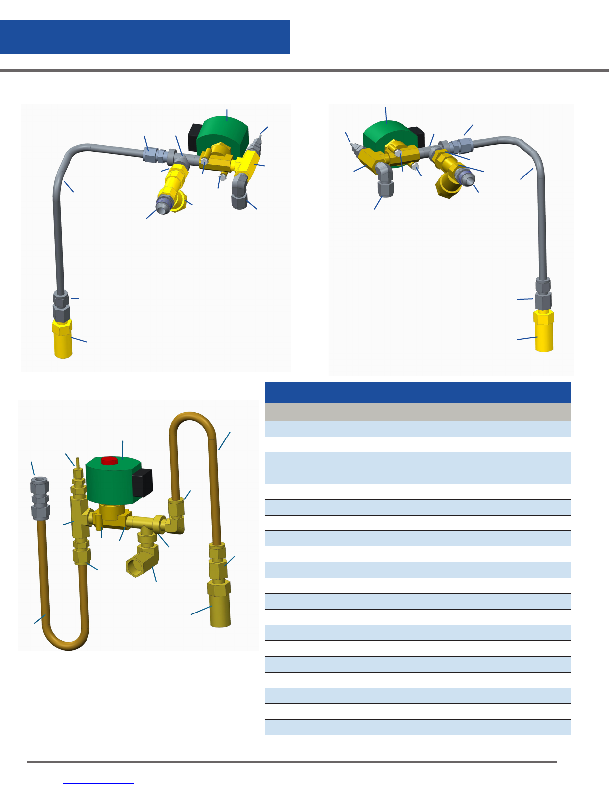
Replacement Parts
Plumbing Assembly
4
12
3
10
Figure 16.0 LABS 38K/40K
2
1
6
5
7
7
6
4
5
12
11
8
13
14
9
8
13
14
11
10
9
Figure 16.1 LABS 20K/80K/94K
3
2
1
17
15
6
7
16
8
13
14
5
18
19
1
Figure 16.2 K Series 10K/24K
15
Plumbing Assembly Parts
Item Part No. Description
1 367276 Valve, Relief, 1/4" MPT, 100 psig
2 367168 Connector, 3/8" ODT x 1/4" FNPT
3 36 7511 Tube, Relief Valve - LABS20K/38K/40K
3674 45 Tube, Relief Valve - LABS80K/94K
4 367175 Con n ect or, M ale 1/4"
5 367265 Tee, Street 1/4" NPT
6 367778 Valve, Solenoid, 2 Way 1/4" FPT, 12 VDC
7 367789 Sensor, Valve Monitoring Assy. (Freeze Guard)
2
8 367267 Tee Branch, 1/4" NPT
9 367169 Elbow, 3/8" ODT x 1/4" MNPT, SS
10 367318 Connector, CGA295 x 3/8" MNPT
11 367326 Strainer, 3/8" NPT, Brass
12 367254 Nipple, HX, RED, BR, 3/8" x 1/4"
13 367246 Washer, Extrenal Tooth #10
14 367723 Screw, Machine, Hex Head, 10-32 UNC x 0.44 LG
15 366889 Tube, Fill Kit
16 367264 Elbow, 90 Deg,. 1/4" MNPT x 3/9" ODT Brass
17 367170 Union 3/8" ODT x 3/8" ODT, SS
18 3 67174 Connector, Male, 3/8" ODT x 1/4" MNPT, Brass
19 367259 Elbow, 90 Deg, Street, 3/8" x 1/4" Brass
CS200 Control Systems
42
Page 43
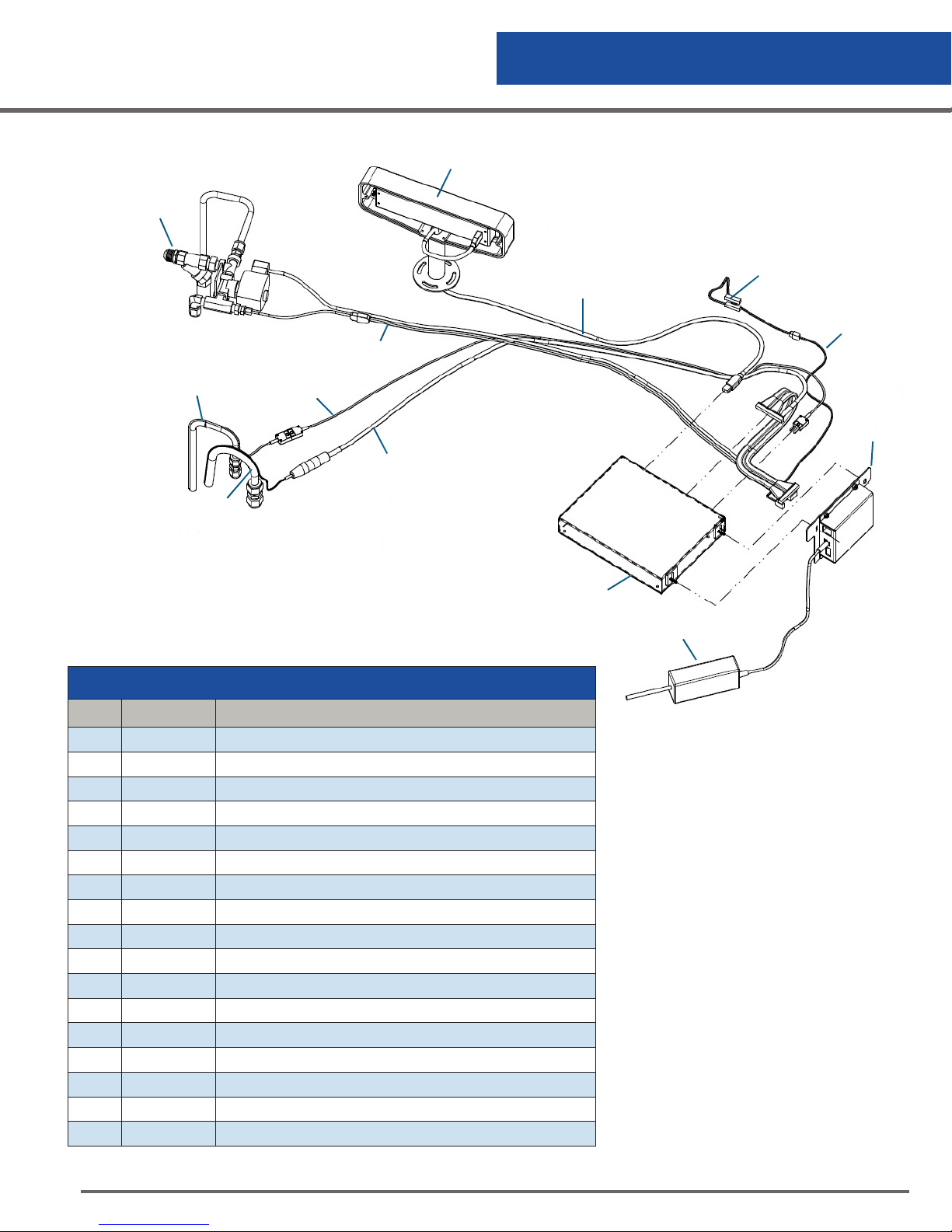
Replacement Parts
Controller Assembly
1
6
9
8
Figure 16.3 LABS Controller Assembly Parts
10
7
2
11
3
12
5
4
Controller Assembly Parts
Item Part No. Description
1 367893 Final Plumbing Assembly LABS20K/38K/40K/80K/94K CS
2 367779 Controller Display, CS200
3 367783 Fire Wire CS LABS20K/38K/40K
367784 Fire Wire CS LABS80K/94K
4 367780 Controller Box, CS LABS
5 367 781 Junction Box, CS LABS
6 367791 Valve/Freezegaurd Harness LABS20K/38K/40K
367792 Valve/Freezegaurd Harness LABS80K/94K
7 367782 Harness Assembly, CS LABS
8 367788 Level Sensor, 8-Thermistor CS200
9 367785 Thermocouple Assembly, CS LABS
10 367786 Thermocouple Wire, Short LABS20K/38K/40K
367787 Thermocouple Wire, Short LABS80K/94K
11 367795 Lid Switch Assembly
12 367796 Lid Switch Extension Wire
13 367823 12 VDC Transformer, EL-V, No Plug
N/S 367185 Remote Alarm Connector
13
CS200 Control Systems
43
Page 44
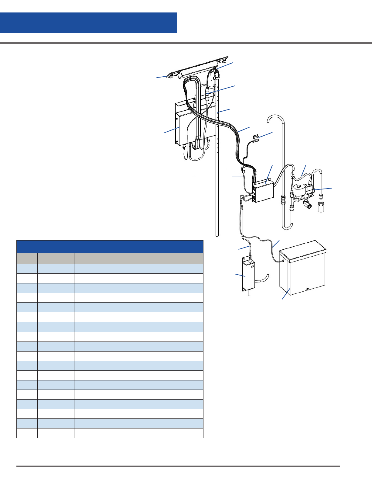
Replacement Parts
Controller Assembly
11, 12, 13
(2x) Connect (ITEM 7)
8, 9, 10
and (ITEM 8)
Sensor Tube
7
6
14
5
2
15
1
Controller Assembly Parts
Item Part No. Description
1 366903 Plumbing Assembly, CS200 Controller
2 367909 Solenoid Valve Harness, K-CS-Series, 36”
3 367823 12 VDC Transformer No Plug
4 367824 Transformer Cover, LABS CS
5 367913 Junction Box, With No T Plate, CS200
6 367908 Controller Module, 10K/24K CS200
7 36 7911 Harness Assembly 10K-CS, 74” Cable
367912 Harness Assembly 24K-CS, 104” Cable
8 367788 Level Sensor, 8-Thermistor CS200 Control
9 366891 Thermocouple Assembly
10 367859 Plug, Sensor Tube
11 367907 CS200 Display Module With Mounting Wings
12 36750 9 Display Module, Bezel
13 367205 Screw, Flat HD, 8-32 UNC X 3/4” LG
14 367795 Lid Switch Assembly
15 367796 Lid Switch Extension Wire
16 367910 Battery Extension Wire
17 367793 Battery
16
3
4
17
Figure 16.4 K Series Controller
Assembly Parts
CS200 Control Systems
44
Page 45

Troubleshooting
Symptoms
The key to troubleshooting your CS200 SERIES Control System and your Cryostorage system is to determine
which component in the system is the source of the problem. Determine if the problem is occurring in any of
the following subsystems: Supply Vessel, Transfer Line, Power Source, Temperature, Level Sensing, Security, Lid
Switch, Solenoid Valve, Control Display, Alarm System, Communications. After determining which subsystem
is having the problem, isolate the problem further by performing subsystem tests. Once the problem is isolated
and defined, it will be easier to solve.
Controller Will Not Turn ON
Press POWER button. If display is blank and dark go to next step.
Check all connections. Power cord must be plugged into an outlet providing100/240 VAC (50/60 Hz).
High Liquid Level
1. Determine physical liquid level using a dipstick, then select MENU, VIEW ONLY, LEVEL, THERMISTOR
STATUS through the controller display. An “L” or “G” will indicate individual thermistor status. “L” indicates
the thermistor is submerged in liquid and “G” indicates that the thermistor is in gas (vapor). A solenoid
valve that fails to close will typically empty the supply cylinder and may cause a high level alarm. Replace
the solenoid valve if it has failed even once.
2. Liquid level is determined by thermistors located in the sensor tube. If the sensor tube is blocked or iced at
the top, the liquid level in the sensor tube may not rise and fall at the same rate as the liquid level in the
freezing chamber. Make sure the sensor tube is not obstructed.
3. The pool of LN2 can become turbulent during a fill. Bubbling and splashing can be amplified by the rack
arrangement. The deeper the pool, the less turbulent the surface of the pool will be during a fill. The
turbulence can cause liquid to splash on a thermistor and cause a false alarm or premature fill termination.
4. Confirm that sensor assembly is responding to changing liquid level with a dip-test.
• Close liquid supply valve at source.
• Mark the sensor assembly with reference to the top of tube to assure the sensor assembly is
reinstalled to the original position.
• Remove sensor assembly from sensor tube. DO NOT FORCE. Solenoid valve should open
and LOW LEVEL alarm should be activated.
• Select MENU, VIEW ONLY, LEVEL, THERMISTOR STATUS. An “L” or “G” will indicate
individual thermistor status (L = Liquid, Gas = Gas, O = Open).
• Dip each thermistor in succession into LN2 Observe the controller display noting that each
thermistor changes from “G” to “L” as each is submerged. Response time may vary.
• Return to the main menu and submerge the START FILL THERMISTOR IN LIQUID. Note that the
low level alarm ceases, fill solenoid valve is still open. Control is flashing FILLING.
• Manually press STOP button and note that the fill solenoid valve closes.
CS200 Control Systems
45
Page 46

Troubleshooting
• Press FILL button to re-open fill solenoid valve.
• Continue to lower the sensor until the STOP FILL thermistor is immersed in the LN2. The fill should
stop after a slight delay.
• Simulate an over fill by lowering the HIGH LEVEL Alarm thermistor into the LN2. HIGH LEVEL
alarm should sound within 10 seconds.
• Re-install sensor assembly and thermocouple into sensor tube as before. Open supply valve on
LN2 supply.
Indicates Low LN2 Supply
When the START FILL thermistor is uncovered, the controller opens the Fill solenoid valve. If the STOP FILL
thermistor is not covered with LN2 in the pre-determined amount of time, the controller is programmed to
interpret this as a LN2 supply shortage.
1. Check contents gauge and pressure gauge of supply cylinder. Both liquid contents and pressure
(15 to 22 psi - 0.7 bar/69 kPa to 1.4 bar/138 kPa) are required to complete a fill.
2. Confirm that no other transfer hose or apparatus is attached to the supply cylinder. Either could
compromise adequate tank pressure required to complete a standard fill in 30 minutes.
• Check the distance that the LN2 must travel to reach the freezer. Observe the time it takes for
Liquid LN2 to reach the Freezer through the usual piping conditions (Pipe-Temperature at start
fill). Liquid should be entering the chamber within 4 minutes under normal (usual) line
temperature conditions.
3. Confirm that the solenoid valve is open when a fill is called for.
• If no flow is detected, the solenoid valve is not getting the signal to open, or it is opening and
there is a blockage in the line. Check the connections on the leads near the solenoid itself, as
well as the connection at the controller.
• Confirm that the wires have not been pinched, creating a short circuit.
4. If a longer fill time is desired, change the setting by selecting: MENU, CHANGE SETTINGS, SYSTEM,
SYSTEM ALARMS, LN2 SUPPLY ALARM DELAYS.
Indicates Open Sensor
1. Normally, this message is associated with a loose plug or connector. Check all connections.
2. To determine this select: MENU, LEVEL SENSING, TEST LEVEL SENSORS. An “L”, “G”, or “O” (open) will
indicate individual thermistor status.
3. Thermistor assembly is not repairable. Replacement assembly is required.
Temperature Reading 10° to 20° Warm
• Prepare an ice water slurry with crushed ice and tap water. Dip or pour LN2 into a styrofoam cup to
prepare an LN2 bath. Calibrate the controller. Select MENU, TEMPERATURE, CALIBRATE TEMPERATURE.
Follow the on-screen instructions. Hold the thermocouple in each bath until the control completes its selfcalibration.
CS200 Control Systems
46
Page 47

Troubleshooting
• Make sure the thermocouple is clean and dry before and after each bath.
• Reposition the thermocouple at the desired location to monitor or control temperature.
Fill Solenoid Cycles On and Off
CS200 SERIES Control System features a timer function whereby the valve open duration is limited, allowed to
shut for a short warm-up and then opened again. To confirm or change the valve open duration:
• Select MENU, USER OPTIONS, CONTROL OPTIONS, FREEZE-GUARD OPTIONS, VALVE OPEN
DURATION.
If the controller Freeze-Guard function detects that the valve is stuck in the open position (i.e., continues to fill
after the valve is de-energized), it will attempt to De-Ice the valve by causing a rapid cycling of the valve in an
attempt to dislodge the blockage.
• To activate or de-activate this feature: Select MENU, USER OPTIONS, CONTROL OPTIONS, FREEZEGUARD OPTIONS, VALVE DE-ICING.
Repeated cycling of the Solenoid Valve, caused by excessive turbulence, power/low battery, bad connection,
or circuit board corrosion, could be attributable to moisture invasion on the controller circuit board.
To troubleshoot proper operation of the fill valve:
1. Confirm the pressure of the supply vessel is less than 22 psi (1.4 bar/138 kPa).
2. Watch the interface panel on the controller to verify if the Start and Stop Fill cycles are repeating. You
should see and hear each cycle.
Solenoid Makes Excessive Humming Noise
During normal operation, the solenoid valve will make a soft humming noise. If the noise is excessively loud,
turn the valve on and off using the control panel. If a soft humming noise is heard, the valve should continue
to operate reliably. If the humming noise is excessive, replace solenoid valve. It is recommended the solenoid
valve be replaced every two (2) years.
Lid Open Alarm
A lid switch is located near the hinge. The proximity switch should actuate when the lid is opened and again
when it is closed.
Confirm that there is a ½ in. (12 mm) gap between the sensors.
QCF (Quick Chill Feature) Will Not Operate
See LID OPEN ALARM
To activate or adjust times: Select MENU, CHANGE SETTINGS, QUICKCHILL, TIMER.
Auto Defog Feature Will Not Operate
See LID OPEN ALARM.
To activate or adjust times: Select MENU, CHANGE SETTINGS, AUTO DEFOG.
CS200 Control Systems
47
Page 48

Troubleshooting
Push Buttons Will Not Respond
Moisture may have migrated into the sealed faceplate. Call your distributor for a Material Return Authorization.
Refer to the Service and Maintenance section of this manual to obtain information regarding equipment returns.
Liquid Level Readout is Incorrect
Liquid level is determined by a 8-thermistor assembly inside the protective sensor tube. The user may adjust
the desired START FILL elevation and STOP FILL elevation for the pool of liquid nitrogen within the confines
of 5 in. (127 mm). START FILL cannot be assigned to thermistor number 1. STOP FILL cannot be assigned to
thermistor number 8. The factory installs 8-thermistor assembly at the bottom of the sensor tube, which positions
thermistor number 1 at 1 in. (25.4 mm) above the floor (i.e.; the first thermistor is offset from the floor zero
inches).
If you would like to stop the fill at a depth greater than seven inches from the floor, the sensor assembly
must physically be raised inside the sensor tube. The distance that it has been raised becomes the new
OFFSET and the controller must be notified of this offset from the floor. The factory settings are START
FILL at 3 in. (76 mm) and STOP FILL at 5 in. (127 mm), with an OFFSET of zero. The factory settings for the
LABS94K are START FILL at 6 in. (152 mm) and STOP FILL at 9 in. (228 mm), with an OFFSET of 3.
Power Failure Alarm
If power is interrupted, a log of the time and duration will be recorded. If the unit is not connected to a battery
back-up or an external alarm, no local alarm will sound unless a high temperature is detected after power is
restored. A Remote Alarm will be triggered anytime the power is interrupted.
CS200 Control Systems
48
Page 49

Troubleshooting
A complete list of Replacement Parts and Accessories for the CS200 Series Controllers is
available from the following Worthington Industries Customer Service Centers:
US Toll Free: 844-273-7517 or Global: +1 614-438-7968 / +43 7485 606 286
SERVICE AND MAINTENANCE HISTORY LOG
Fill in top section at installation. Copy this form each time service is required.
Fill bottom section with service notes to keep a complete log of each freezer service and maintenance history.
End User Company Name __________________________________ LOG NO ______________________________
Service Contract/Company Name __________________________________________________________________
Service Contract Phone Number/Fax _______________________________________________________________
Model/Serial Number ____________________________________________________________________________
Controller Serial Number __________________________________________________________________________
Controller Version Number ________________________________________________________________________
In-service Date ___________________________________________________________________________________
Describe Conditions – Actual
Liquid Level – via Dipstick ______________________ Liquid Level – Per Controller _______________________
Level Sensor Type _____FG _____ 8T _______ _____ Liquid Level Setting ______ HIGH ____ LOW
Lid _____ Open _____ Closed Lid _____Open _____ Closed
Filling _____ Yes _____ No Filling _____ Yes_____ No
Temperature __________________________________ Temperature _____________________________________
LN2 Supply ______________ ltr______________ psi Supply Alarm ______On _______ Off
Note: Ice Build-up _____a little _____a lot Remote Alarm ______ On _______Off
Note: Gasket condition _____ Seals _____ Leaks Audible Alarm _____ On _______Off
Display Lights _____ On _____ Off Temp. control set point @ __________ degrees
Worthington Industries Technical Services
Phone: US Toll Free: 844-273-7517 Global: +1 614-438-7968 / +43 7485 606 286
Email: [email protected]
Service History Log (note date and log number on each service entry)
Date: ___________________________________________________________________________________________
Date: ___________________________________________________________________________________________
Date: ___________________________________________________________________________________________
Date: ___________________________________________________________________________________________
Date: ___________________________________________________________________________________________
Date: ___________________________________________________________________________________________
Date: ___________________________________________________________________________________________
NOTE: All Worthington Industries Cryostorage Systems must be cleaned and decontaminated prior to return to Worthington Industries
for repair or maintenance and must be accompanied by a written statement to this effect. Any Cryostorage System received without this
statement will be returned to the sender, freight collect. Contact Customer Service by telephone: US Toll Free: 844-273-7517
Global: +1 614-438-7968 / +43 7485 606 286. Or email: [email protected].
Describe Conditions – Controller Reading
CS200 Control Systems
49
Page 50
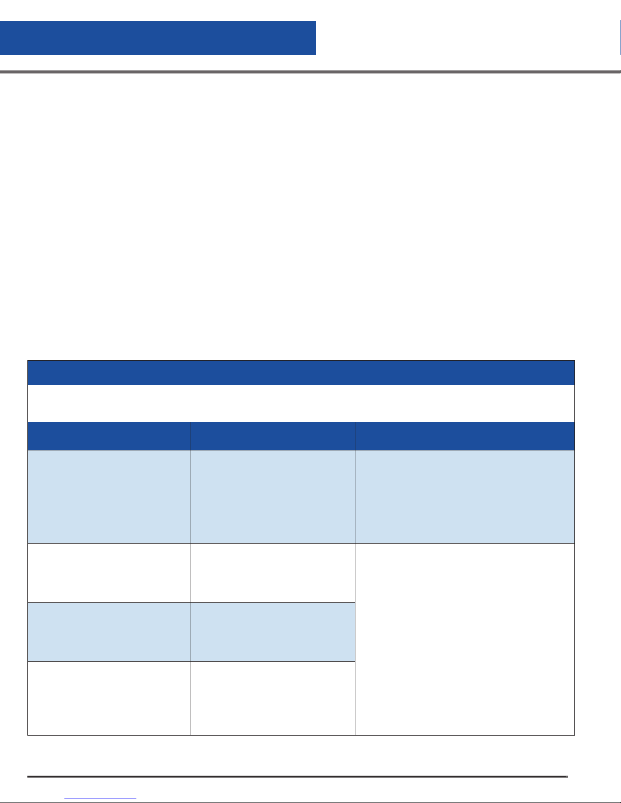
Appendix
Certifications & Listings
This product complies with the following standards and directives:
• CB Scheme Report and Certificate
• EN 60101-1
• IEC 61010-1
• UL 61010-1
• CAN/CSAC22.2#61010-1
• 93/42/EEC Medical Device Directive for the European Union
• IEC 60601-1-2, 2007 Edition 3.0 (EMC Directive)
• RoHS Directive
• WEEE Directive
• Packaging Directive
• ETL/cETL Listing for North America
• CE marked to the Low Voltage Directive
TABLE 10: Guidance and Manufacturer’s Declaration – Electromagnetic Emissions
The CS CONTROL SYSTEM is intended for use in the electromagnetic environment specified below.
The customer or the end user of the CS CONTROL SYSTEM should assure that it is used in such an environment.
Emissions test Compliance
RF Emissions - CISPR 11
(Radiated & Conducted)
RF Emissions - CISPR 11
(Radiated & Conducted)
Harmonic Emissions
EN/IEC 61000-3-2
Group 1
Class B
Class A
The CS CONTROL SYSTEM uses RF energy
only for its internal function. Therefore, its RF
emissions are very low and are not likely to
cause any interference in nearby electronic
equipment.
The CS CONTROL SYSTEM is suitable for use in
all establishments, including domestic establishments and those directly connected to the public
low-voltage power supply network that supplies
buildings used for domestic purposes.
Electromagnetic
environment - guidance
Voltage fluctuations/
Flicker Emissions
EN/IEC 61000-3-3
Complies
CS200 Control Systems
50
Page 51
Appendix
TABLE 11: Guidance and Manufacturer’s Declaration – Electromagnetic Immunity
The CS CONTROL SYSTEM is intended for use in the electromagnetic environment specified below.
The customer or the end user of the CS CONTROL SYSTEM should assure that it is used in such an environment.
Immunity Test
Electromagnetic
Discharge (ESD)
EN/IEC 61000-4-2
Electrical fast transient/
burst
EN/IEC 61000-4-4
Surge
EN/IEC 61000-4-5
Voltage dips, short interruptions and voltage variations on power supply
input lines
EN/IEC 61000-4-11
EN/IEC 60601
Test Level
± 6kV contact
± 8kV air
± 2kV for power supply
lines
± 1kV for input/output
lines
± 1kV differential mode
(line-line)
± 2kV common mode
(line-earth)
<5% UT (>95% dip in UT)
for 0.5 cycle
40% UT (60% dip in UT)
for 5 cycles
70% UT (30% dip in UT)
for 25 cycles
<5% UT (>95% dip in UT)
for 5 seconds
Compliance Level
± 6kV contact
± 8kV air
± 2kV for power supply
lines
± 1kV for input/output
lines
± 1kV differential mode
(line-line)
± 2kV common mode
(line-earth)
<5% UT (>95% dip in UT)
for 0.5 cycle
40% UT (60% dip in UT)
for 5 cycles
70% UT (30% dip in UT)
for 25 cycles
<5% UT (>95% dip in UT)
for 5 seconds
Intended
Electromagnetic
Environment
Floors should be wood, concrete or
ceramic tile. If floors are covered with
synthetic material, the relative humidity should be at least 30%.
Mains power quality should be that
of a typical commercial or hospital
environment.
Mains power quality should be that
of a typical commercial or hospital
environment.
Mains power quality should be that
of a typical commercial or hospital
environment. If the user of the CS
CONTROL SYSTEM requires continued operation during power mains interruptions, it is recommended that the
CS CONTROL SYSTEM be powered
from an uninterruptible power supply
or a battery.
Power frequency
(50/60Hz) magnetic field
EN/IEC 61000-4-8
Note UT is the a.c. mains voltage prior to application of the test level.
3A/m 3A/m Power frequency magnetic fields
should be at levels characteristic of a
typical location in a typical commercial or hospital environment.
CS200 Control Systems
51
Page 52
Appendix
TABLE 12: Guidance and Manufacturer’s Declaration – Electromagnetic Immunity
The CS CONTROL SYSTEM is intended for use in the electromagnetic environment specified below.
The customer or the end user of the CS CONTROL SYSTEM should assure that it is used in such an environment.
Immunity Test
Conducted RF
EN/IEC 61000-4-6
Radiated RF
EN/IEC 61000-4-3
EN/IEC 60601
Test Level
3Vrms
150kHz to
80MHz
3V/m
80MHz to
2.5GHz
Compliance
Level
3Vrms
150kHz to
80MHz
3V/m
80MHz to
2.5GHz
Intended Electromagnetic
Environment
Portable and mobile RF communications equipment should
be used no closer to any part of the CS CONTROL SYSTEM, including cables, than the recommended separation
distance calculated from the equation applicable to the
frequency of the transmitter.
Recommended separation distance
d = 1.2√P
d = 1.2√P 80MHz to 800 MHz
d = 2.3√P 800MHz to 2.5GHz
where P is the maximum output power rating of the transmit-
ter in watts (W) according to the transmitter manufacturer
and d is the recommended minimum separation distance in
meters (m).
Field strengths from fixed RF transmitters, as
determined by an electromagnetic site surveyA, should be
less than the compliance level in each frequency rangeB.
Interference may occur in the
vicinity of equipment marked
with the following symbol:
NOTE 1: At 80MHz and 800MHz, the higher frequency range applies
NOTE 2: These guidelines may not apply in all situations. Electromagnetic propagation is affected
by absorption and reflection from objects, structures and people.
A. Field strengths from fixed transmitters, such as base stations for radio (cellular/cordless) telephones and land mobile
radios, amateur radio, AM and FM radio broadcast and TV broadcast cannot be predicted theoretically with accuracy. To
assess the electromagnetic environment due to fixed RF transmitters, an electromagnetic site survey should be considered.
If the measured field strength in the location in which the CS CONTROL SYSTEM is used exceeds the applicable RF compliance level above, the CS CONTROL SYSTEM should be observed to verify normal operation. If abnormal performance is
observed, additional measures may be necessary, such as re-orienting or relocating the CS CONTROL SYSTEM.
B. Over the frequency range 150kHz to 80MHz, field strengths should be less than 3V/m.
CS200 Control Systems
52
Page 53
Appendix
TAB LE 13
Recommended separation distances between portable and mobile RF communications equipment
and the CS CONTROL SYSTEM.
The CS CONTROL SYSTEM is intended for use in an electromagnetic environment in which radiated RF disturbances
are controlled. The customer or the user of the CS CONTROL SYSTEM can help prevent electromagnetic interference by
maintaining a minimum distance between the portable and mobile RF communications equipment (transmitters) and the CS
CONTROL SYSTEM as recommended below, according to the maximum output power of the communications equipment.
Separation distance according to frequency of transmitter in meters (m)
Rated maximum output power of transmitter in watts
(W)
0.01 .12 .12 .23
100 12 12 23
For transmitters rated at a maximum output power not listed above, the recommended separation distance d in meters (m)
can be estimated using the equation applicable to the frequency of the transmitter, where P is the maximum output power
rating of the transmitter in watts (W) according to the transmitter manufacturer.
NOTE 1: At 80 MHz and 800 MHz, the separation distance for the higher frequency range applies.
NOTE 2: These guidelines may not apply in all situations. Electromagnetic propagation is affected by absorption and
reflection from structures, objects and people.
150kHz to 80MHz
d = 1.2√P
0.1 .38 .38 .73
1.0 1.2 1.2 2.3
10 3.8 3.8 7. 3
80MHz to
800MHz
d = 1.2√P
800MHz to 2.5GHz
d = 2.3√P
CS200 Control Systems
53
Page 54

Appendix
EC Declaration of Conformity
The undersigned representing the manufacturer:
Pacer Digital Systems, Inc.
Attn: Kevin Oeff
8658 Castle Park Drive, Suite 103
Indianapolis, IN 46256, USA
Herewith declared that the Product: LN2 Level Control for Cryostorage System
Model/Type ref.: CS CONTROL SYSTEM
is in conformity with the Essential requirements of the following EC Directives when subject
to correct installation, maintenance and use conforming to its(their)intended purpose, to the
applicable regulations and standards, to our operation and maintenance manual.
93/42/EEC Medical Device Directive
2004/108/EC EMC Directive
2006/95/EC Low Voltage Directive
and that the Standards and/or technical specifications referenced below
have been applied:
• EN 60601-1:2006+A11:2001 Medical Electrical Equipment – General Requirements
for basic safety and essential performance.
• IEC 61010-1:2001 (Second Edition)- Safety requirements for electrical equipment for
measurement, control, and laboratory use Part 1: General requirements
• IEC 60601-1-2: 2007 Edition 3 Medical Electrical Equipment – General Requirements for basic safety and
essential performance – Collateral standard : Electromagnetic Compatibility
• IEC/CISPR 11:2009+A1:2010 Radiated & Conducted Emissions.
• IEC61000-3-2:2005+A1:2008+A2:2009. Harmonics
• IEC 61000-3-3:2008. Flicker
Year of CE Marking: 2012
Manufacturer: Pacer Digital Systems, Inc.
Signature: Kevin Oeff (Digitally signed by Kevin Oeff)
Position: President
Date: 24 May 2012
Place: Indianapolis, IN USA
CS200 Control Systems
54
Page 55
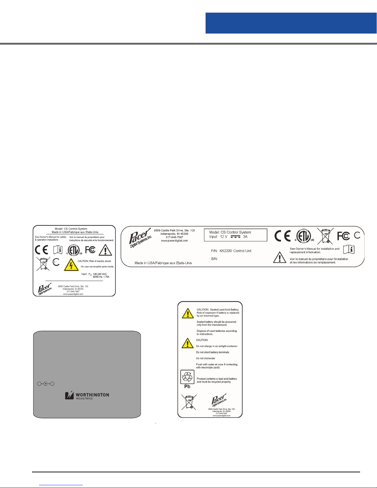
Appendix
Warranty
Worthington Industries warrants that each of its electronic controllers and displays will be free from defects in
material and workmanship, in the normal service for which the product was manufactured, for a period of two
(2) years from the original date of purchase. Worthington Industries at its option will either repair or replace any
item covered under this warranty.
This warranty is void if the product is used for any other purpose than that for which it was designed, including
but not limited to connection with third party systems. This warranty is void if the product is in any way altered
or repaired by others. Worthington Industries and/or its suppliers shall not be liable under this warranty, or
otherwise, for defects caused by negligence, abuse or misuse of this product, corrosion, fire or the effects of
normal wear.
The remedies set forth herein are exclusive. Worthington Industries shall not be liable for any indirect or
consequential damages including, without limitation, damages relating to lost profits or loss of products,
resulting from the delivery, use or failure of the product or for any other cause. By accepting delivery of the
product, the purchaser acknowledges that this limitation of remedies is reasonable and enforceable. In no
case shall Worthington Industries’ liability exceed the purchase price for the product.
Labels
Figure 17.0
Main Rating Label
Cryowire
Network
Power
12 VDC, 3A
+-
Figure 17.1 Control & Display Label
Cryowire
Network
Cryowire
Local
Battery
12V, 2.5A
4075 Hamilton Blvd.
Theodore, AL 36582
844-273-7517 / +1 614-438-7968
WorthingtonIndustries.com
Remote
Alarm
Figure 17.2 Connector Box Label Figure 17.3 Battery Label - (Optional)
NO
C
NC
CS200 Control Systems
55
Page 56

CONTACT US
US Toll Free: 84 4-273 -7517
Global: +43 7485 606 286 / +1 614-438-7968
Sales Support/Order Placement:
Technical Services:
©2017 Worthington Industries. All rights reserved. CS200 Controller Operation Manual P/N 372409 - 01/17
7950-8346
 Loading...