

Page 1

RF Laser Users Manual and
Setup Menu
Worth Data Inc.
August 2006
Page 2

The LZ400-RF and the B78 Base Station have been tested and found to comply with the limits for a Class A
digital device, pursuant to Part 15 of the FCC Rules. These limits are designed to provide reasonable protection
against harmful interference in a residential installation. This equipment generates, uses and can radiate radio
frequency energy and, if not installed and used in accordance with the instructions, may cause harmful
interference to radio communications. However, there is no guarantee that interference will not occur in a
particular installation. If this equipment does cause harmful interference to radio or television reception, which
can be determined by turning the equipment off and on, the user is encouraged to try to correct the interference
by one or more of the following measures:
• Reorient or relocate the receiving antenna.
• Increase the separation between the equipment and receiver.
• Connect the equipment into an outlet on a circuit different from that to which the receiver is
connected.
• Consult the dealer or an experienced radio/TV technician for help.
Shielded cables and I/O cords must be used with this equipment to comply with the relevant FCC regulations.
Changes or modifications not expressly approved in writing by Worth Data may void the user's authority to
operate this equipment.
This device complies with Part 15 of the FCC Rules. Operation is subject to the following two conditions: (1)
this device may not cause harmful interference, and 2) this device must accept any interference received,
including interference that may cause undesired operation.
This device complies with RSS-210 of Industry Canada. Operation is subject to the following two conditions: 1)
this device may not cause interference, and 2) this device must accept any interference, including interference
that may cause undesired operation of the device.
The laser used is a Class II Laser Product and has a 1.2 Milliwatts Output. To operate the laser scanner, aim the
scanner at the bar code, and pull the trigger. The light source will turn off, once a successful scan has occurred or 2.5
seconds has elapsed, whichever is first. Do not look directly into the laser light source with the trigger depressed;
avoid direct eye contact with the laser light source.
Page 3

Table Of Contents
RF Laser Reader Users Manual
Introduction.....................................................................................................1
Installation.......................................................................................................2
Configuring the RF Laser Reader .................................................................7
for your computer and application................................................................7
Radio Considerations....................................................................................22
Accumulate Mode..........................................................................................23
Function/Control Key Support ....................................................................24
Troubleshooting.............................................................................................26
Changing Jumpers and Channels................................................................29
Recharging the Batteries ..............................................................................31
Specifications for Code 39 ............................................................................32
Code 93 Specifications ..................................................................................35
Codabar Specifications.................................................................................36
Code 128 Specifications ................................................................................37
Interleaved 2 of 5 Code.................................................................................39
UPC Specifications........................................................................................41
MSI/Plessey Specifications ...........................................................................45
RF Laser Setup Menu...................................................................................47
Index...............................................................................................................54
4/06
Page 4

Introduction
The Worth Data RF Laser has the following features:
1) The LZ400-RF Laser Scanner
a range of up to 500 feet (open area) and has collision detect and retry
logic built within. The LZ400-RF Laser communicates with the B78
Base Station. The Base Station communicates with a host PC through the
USB port or a RS-232 Serial Port. Up to ten LZ-400 RF Lasers can
communicate with one B78 Base Station.
2) If you use the USB interface, data is transmitted as keyboard data. If you
use the serial interface instead, serial data is transmitted to one of the
computer's COM ports.
3) The USA LZ400-RF Laser and Base operate in the 902MHz band. The
laser and base radios operate by "frequency hopping" spread spectrum.
The radios hop from one frequency to another every 400ms. The radio
goes through 25 different frequencies and then repeats the sequence – all
in the 902 MHz band at 15 milliwatts (10 dBm) of power. Different
sequences define the channels. It is possible to have up to ten RF
Lasers/Base Stations in the same area, providing each pair is on separate
channels to avoid interference and general confusion. The RF Laser can
also operate in the same room as the 701 RF Terminal.
4) The R/F Laser can read and discriminate between Code 39, Full ASCII
Code 39, Interleaved 2 of 5, Codabar, Code 128, EAN-13, EAN-8, UPCE, UPC-E1, UPC-A, MSI, LabelCode4, LabelCode5, Code 93 and
Plessey.
5) The RF Laser has a rechargeable lithium ion battery. The battery is
recharged with the included F10 5v power supply. Recharge time on
fully discharged batteries is 3 hours. Do NOT use any other power
supply to charge your laser.
for the USA and Canada. This laser has
1
Page 5

Installation
Components of RF Laser Readers
In the event the shipping box shows damage on arrival, please note the
damage on the carrier's receipt log.
The supposed contents of your Reader shipment is the following:
1. An B78 RF Base Station with 1-10 LZ400-RF Lasers.
2. A Worth Data regulated 5V power supply with each LZ400-RF Laser
Scanner ordered, and if you ordered a serial cable with the B78 Base
Station, you will receive a power supply for the Base also. TO
PREVENT DAMAGING the Base Station or RF Laser, DON'T USE
ANY OTHER BRAND OF POWER SUPPLIES.
3. Either a serial cable (F36) or USB cable (C21), depending on which one
you ordered.
4. A plastic barpad for entering variable quantity information and
performing the Link Test without data transmission.
Scanner Beeps and LEDs (what they mean)
When you scan, you will get one beep when you get a successful decode and a
high-pitched beep. The data is then transmitted to the Base Station (as it is
being transmitted, the LED flashes yellow). When the Laser receives the
acknowledgement from the Base Station that the data has been received, the
Laser emits a lower pitched beep and turns on a green LED for three seconds.
If the transmitted data fails to be acknowledged,
1) further scanning is prohibited. You can't pull the trigger again
until the data reaches the base or until you clear the scanner.
2) The laser will retransmit three times, (the yellow LED will
indicate retransmissions).
3) If it fails three times, it will emit a distinct 8 beep pattern and
turn off. This is your clue to check out the Base Station.
4) You can pull the trigger to try transmission again. (the laser beam
will not come on until the transmission is acknowledged or you
hold the trigger down for 30 seconds to clear the data).
2
Page 6
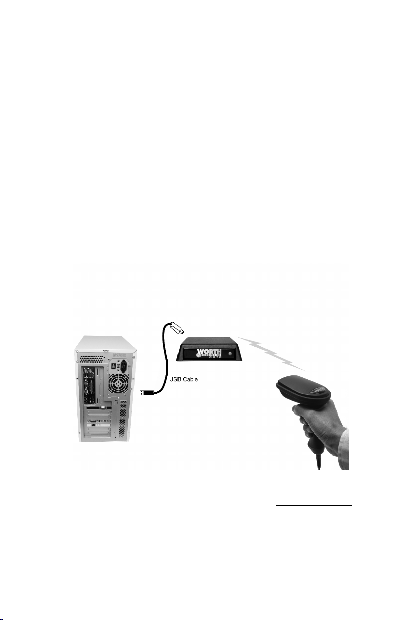
USB Installation
USB attachment does not require the Worth Data F10 5v power supply for the
B78 Base Station. If for some reason your USB port or hub does not have
enough power to operate the Base Station correctly, you may use our F10
power supply, but you must plug it in AFTER you have powered up on the
USB cable only. The Base Station will power up with 3 more flashes than the
channel setting; i.e. if it is set on Channel 0, it will flash green three times. If
the Channel were set to 7, it would flash green 10 times.
Once you connect the B78 Base Station to the computer using the supplied
USB cable, the Base Station should be sensed automatically by the computer
and the driver installation will begin. Windows can usually find the necessary
driver on the hard drive under /Windows/System 32/Drivers; occasionally you
will have to insert the original Windows CD. The Mac always finds the driver.
In either case, the driver used is the standard keyboard driver. No special
drivers are required.
You should be connected as below:
If you mistakenly abort your driver installation, see the Trouble Shooting
Section of this manual.
For testing, bring up Notepad or WordPad on your computer and scan the
TEST LABEL on page 21. Now turn to page 7.
3
Page 7
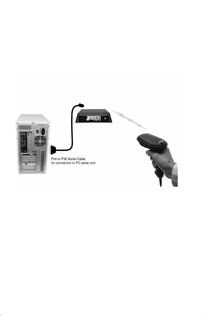
Installing the R/F Reader with a dedicated serial port
The Base Station can be directly attached to a spare serial port as shown
below. This configuration requires the Worth Data F10 5v power supply for
powering the Base Station. Upon power-up, the Base Station LED will flash
with 3 more flashes than the channel setting; i.e. if it is set on Channel 0, it
will flash green three times. If the Channel were set to 7, it would flash green
10 times.
Your software will need to read the serial port as a separate device, unless
you're using an IBM-compatible computer and Worth Data’s PortKey
software, which makes serial-port data appear as though it had been typed at
the keyboard. You can also use the WDR Test Utility to test communication
with your com port.
If you specified a 25-pin null-modem cable (part number F34) or a 9-pin cable
(part number F36) when you placed your order, you can cable directly from
the RF/Reader's Y-Cable port to your computer's serial port. Refer to page 6
for the details of the pin-outs of the cables.
Turn to page 7 to configure the RF Laser Reader using the Setup Menu.
4
Page 8
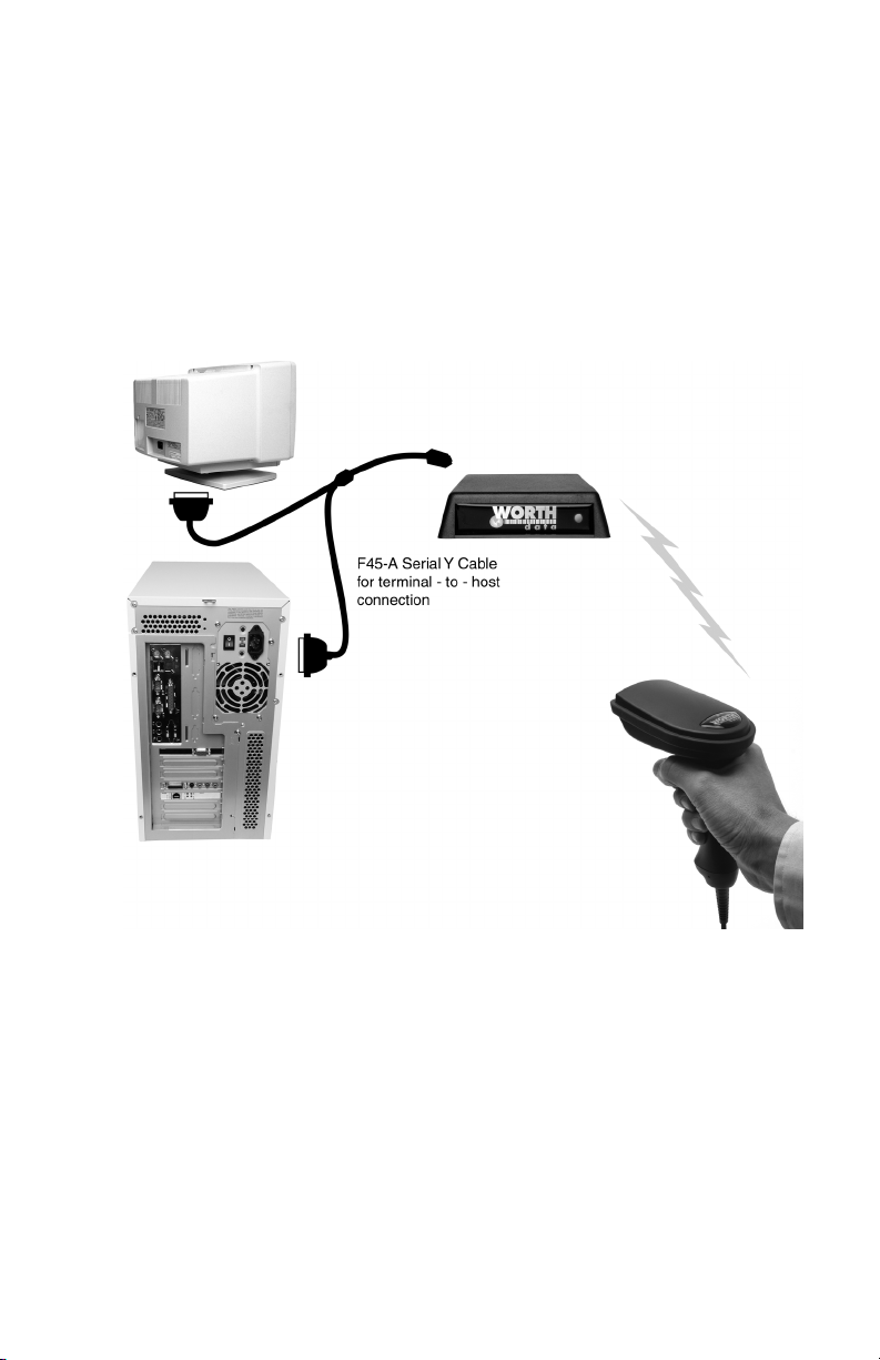
Installing the R/F Reader between a computer and
terminal
If you attach the s Base between your computer and a terminal, as shown
below, using Cable Selection F45-1, bar code data will be sent to the computer
as if it had been typed on that terminal. Refer to page 8 for the details of the
pin-outs for each connector on the cable. You will also need to change jumpers
(JP2 on the RF Base) on the board inside the case from the “S” position to the
“Y” position.
This configuration requires the Worth Data F10 5v power supply for powering
the Base Station. Upon power-up, the Base Station LED will flash with 3 more
flashes than the channel setting; i.e. if it is set on Channel 0, it will flash green
three times. If the Channel were set to 7, it would flash green 10 times.
Cables may require modification, depending on the genders and pin-outs of
your serial ports and cables. You may require "gender changers" (available at
most computer stores) for the two 25-pin connectors. Refer to page 6 for the
details of the pin-outs of the dual port serial cable.
Turn to page 7 to configure the reader using the RF Laser Reader Setup
Menu.
5
Page 9

R/F Laser Serial Model Pin-outs
F34, DB25 Null Modem Cable
These are the pin-outs for Cable F34, a DB25 Female, with pins 2 and 3
crossed, used for connection directly to a DB25 male host COM.
Mod 8 DB25F
Function Pin Pin
Frame Ground 1 1
Transmit Data 2 3
Receive Data 3 2
Signal Ground 4 7
F36, DB9 Straight Cable Pin-outs
These are the pin-outs for the DB9 Female Straight Cable, F36, used for
connection of the Base directly to a DB9 Male host COM.
Function Pin Pin
Shell (Chassis Ground) 1 Shell
Transmit Data 2 2
Receive Data 3 3
Signal Ground 4 5
F45-1, Dual Port Serial Cable
If you want to install the Base between a serial terminal and a host computer,
(as with Unix, PICK, VM, etc.), you need the Dual Port Serial Port Cable,
F45-1. This cable has three connectors: 1) Host, 2) Terminal, and 3) Scanner.
This cable is configured so that the Terminal End connects directly into the
female main port of the Terminal; the female Host End connects into the
DB25 male cable end (a cable with pins 2 and 3 crossed is assumed to have
been connected between the host terminal).
Dual Port Cable’s
Host Connector
Frame Ground 1 Frame Ground
Transmit Data 2 Receive Data
Receive Data 3 Transmit Data
RTS 4 RTS
CTS 5 CTS
DSR 6 DSR
Signal Ground 7 Signal Ground
DTR, CD 8,20 CD, DTR
Mod 8 DB9F
Pin Number
Dual Port Cable’s
Terminal Connector
6
Page 10
Configuring the RF Laser Reader
for your computer and application
The RF Laser Setup Menu is located in Appendix J of
this manual. This simple menu lets you easily configure
the RF Laser to work with almost any computer system,
and to tailor its bar code reading and data format
characteristics.
Be sure to read the scanning instructions on the next
page. To read Reader Setup Menu bar codes and
configure your reader, you must know the right way to
scan bar codes.
These are the RF Laser Reader's default settings and are shipped configured to
these settings; they can be reset to them at any time by scanning the Start
Setup and Reset codes on the RF Laser Setup Menu.
Code 39 UPC\EAN
• Enabled • Enabled
• Check digit disabled
• Accumulate Mode enabled • UPC-E Compressed / NSC of 0
• Caps Lock Off • UPC-A NSC and EAN-13 1st 2 characters
• Start/stop characters not transmitted and check digits transmitted
2 of 5 Code
• Disabled & check digits not transmitted
• I 2 of 5 Code Disabled RSS-14
• 6-digit code length • Disabled
• Check digit disabled
Code 128
• Enabled • CR for Terminator Character
• UCC/EAN-128 options disabled • No preamble or postamble
Codabar
• Disabled • No Aiming Dot
• CLSI Format disabled
• Start/stop characters not transmitted • 9600 Baud Rate
MSI/Plessey
• Disabled • 1 Stop Bit
• Check digit(s) not transmitted • Parity is None
Code 93
• Disabled
• Full ASCII disabled
Be certain to turn off any bases with common channels before setting up.
If you need to change any of the default settings, or would like to learn more
about the RF Laser options, the next section will explain the different settings
and how to set up your RF Laser.
• UPC supplements disabled
• UPC-E NSC and EAN-8 1st 2 characters
General RF Laser configuration settings
• Channel 0
• Low Power
RF Base Configuration
• 8 Data Bits
• Protocol is None
7
Page 11
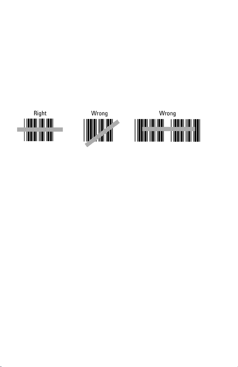
Laser Scanning Instructions
Using a laser scanner is basically as simple and intuitive as "point and shoot"
at a distance of 0-24", depending on the density of the bar code.
Basically, the laser scanner's beam must cross every bar and space on the bar
code, without touching any other bar codes, as shown in the first example
below. You'll need to hold the scanner further away to produce a wider beam
for large bar codes, and closer for bar codes with bars very close together.
Even though momentary exposure to a laser's low-power, visible-light is not
known to be harmful, you should not aim the beam into anyone's eyes.
When you scan, you will get one beep when you get a successful decode and a
high-pitched beep. The data is then transmitted to the Base Station (as it is
being transmitted, the LED flashes yellow). When the Laser receives the
acknowledgement from the Base Station that the data has been received, the
Laser emits a lower pitched beep and turns on a green LED for three seconds.
If the transmitted data fails to be acknowledged,
1) further scanning is prohibited. You can't pull the trigger again
until the data reaches the base or until you clear the scanner.
2) The laser will retransmit three times, (the yellow LED will
indicate retransmissions).
3) If it fails three times, it will emit a distinct 8-beep pattern and
turn off. This is your clue to check out the Base Station.
4) You can pull the trigger to try transmission again. (the laser beam
will not come on until the transmission is acknowledged or you
hold the trigger down for 30 seconds to clear the data).
The important thing to remember about using a laser with the RF Laser Reader
Setup Menu is that you need to make sure the scanner's beam covers only one
bar code at a time. The laser scanner's beam is wide enough, and the
configuration bar codes close together enough, that you will need to use your
fingers, post-it notes, or the supplied Laser Setup Assist window, to "block
off" bar codes adjacent to whatever configuration bar code you need to read.
8
Page 12
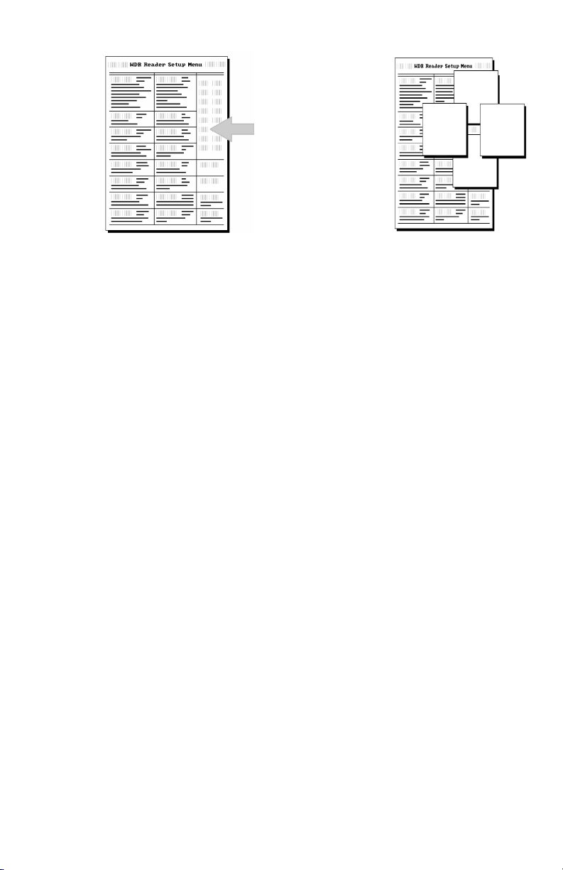
For example, to
read this "5" bar
code on the Setup
Menu, you would
need to cover any
adjacent bar codes
with paper or a
finger first, as
shown.
Don't forget to take the R/F Laser Scanner of Setup Mode by scanning End
Setup, otherwise the batteries will run down totally because the radio
transmitter remains on.
Using The RF Laser Setup Menu
1. To configure your reader using the Reader Setup Menu found in Appendix J
of this manual. You must first scan the Start Setup code at the top left corner.
Do this now. You'll hear two beeps. During Setup, nothing will be
transmitted to your computer; the RF Laser Setup Menu codes are strictly for
configuring the reader. If you did not hear two beeps, try scanning the code
again, until you hear the two beeps. If you've never scanned bar codes before,
read the scanning instructions on page 8 before continuing.
2. Next, choose the parameter you want to change an option for, and scan its
code (i.e. Code 3 of 9, or Postamble). You should hear two beeps if you
scanned correctly.
3. Then, choose the option you want to change from the list below the
parameter bar code you just scanned, and scan the number on the barpad
that corresponds to that option. For example, if you scanned the parameter
“Codabar” and wanted to “Enable Codabar”, you would scan the number
0 on the barpad.
4. Now scan End Setup (at the top-right corner of the Reader Setup Menu to
complete the setup exercise. If you scanned correctly, you'll hear three beeps.
Continue scanning topics and options until you've made all the changes you
desire, and then scan End Setup to complete setup. If you are planning to use
several RF Laser scanners with one base station, pay attention to the Set ID
parameter.
The next several pages will show you all of the various RF Laser options.
Default settings are shown in bold in this manual and marked with an * on the
RF Laser Setup Menu.
9
Page 13

RF Laser Setup Parameters
Channel
Default Channel
0
• The default Channel is always shipped as 0. There are 10 channels
in the USA and Canada. The Channel for the RF Laser Reader is set
by scanning the Setup Menu.
• All Lasers and associated Base Station must be set to the same
channel. If you have more than one RF Laser per Base Station, you
must set a unique ID in each RF Laser. (See SET ID.)
• The Laser channel must match the channel on the Base station. See
Appendix A for information on changing the channel on the Base
from the shipped default channel of 0.
Code 3 of 9 (Code 39)
Enable Code 39 0
Disable Code 39 1
Enable Full ASCII Code 39 2
Disable Full ASCII Code 39 3
Enable Code 39 Accumulate Mode 4
Disable Code 39 Accumulate Mode 5
Enable Start/stop character transmission 6
Disable Start/Stop character transmission 7
Enable Mod 43 Check Digit 8
Disable Mod 43 Check Digit 9
Enable Check Digit Transmission A
Disable Check Digit Transmission B
Caps Lock ON C
Caps Lock OFF D
For information about Code 39 and Full ASCII Code 39, see Appendix C.
See page 23 for information about Accumulate Mode (this setting also
controls Code 93 and Code 128).
Enabling Start/Stop character transmission means that the RF Laser Reader
will transmit the * Start/Stop characters to your computer along with the data.
For example, data of 1234 would be transmitted as *1234*.
Enabling the Mod 43 Check Digit requires the units position of your data to
match the calculation for the check digit explained in Appendix C.
10
Page 14

If you've enabled the check digit, enabling Check Digit transmission causes
the reader to transmit it to your computer along with the bar code data.
"Caps Lock ON" means that for all codes lower case letters read as data will be
transmitted as upper case, and upper case as lower. Numbers, punctuation &
control characters are not affected. This applies to Code 128 and Code 93 also.
"Caps Lock OFF" means that letters will be transmitted exactly as read.
UPC/EAN
Enable UPC/EAN 0
Disable UPC/EAN 1
Enable UPC/EAN Supplements 2
Disable UPC/EAN Supplements 3
Enable transmission of UPC-A NSC and EAN-13 1
Disable transmission of UPC-A NSC and EAN-13 1
Enable transmission of UPC-A and EAN–13 Check Digit 6
Disable transmission of UPC-A and EAN-13 Check Digit 7
Enable transmission of UPC-E NSC and EAN-8 1
Disable transmission of UPC-E NSC and EAN-8 1
Enable transmission of UPC-E and EAN-8 Check Digit A
Disable transmission of UPC-E and EAN-8 check Digit B
UPC-E Compressed C
UPC=E Expanded D
EAN-8 observes 9 & A above E
EAN-8 is forced to transmit 8 digits F
For more information on UPC and EAN, see following page and Appendix H.
Enabling supplements allows you to read 2 and 5-digit supplemental codes
used with magazines and paperbacks. This disallows right-to-left reading of
UPC codes, to assure that the supplement doesn't get skipped.
Use setting 2 to enable reading of the 2 and 5 digit UPC/EAN supplements
commonly found on magazines and paperback books. Use this setting to force left
to right reading of UPC codes, assuring that the supplement code is not missed.
This setting also allows for reading of the UCC/EAN 128 Extended Coupon Code.
The Extended Coupon Code consists of a UPC code with a NSC of 5 or and EAN
code with a country code of 99 along with a Code 128 supplemental code to the
right. This setting allows you to read the Code 128 supplement with the
UPC/EAN, providing the UPC has a NSC of 5 or the EAN code has a country
code of 99. Without the correct NSC or country code, the Code 128 portion will be
ignored; UPC code with an NSC of 5 or EAN codes with country code of 99 will
not be read unless there is a readable Code 128 supplemental code read also.
UPC-E Compressed Format transmits UPC-E codes as is; Expanded
Format adds zeros to make them the same length as UPC-A.
st
2 4
st
1 digits 5
st
Digit 8
st
Digit 9
11
Page 15

UPC-E can be used in either normal UPC-E format (implicit NSC of 0) or
UPC-E1 format (NSC of 1). UPC-E1 is enabled by scanning 2 of 5 Code and
8 (9 disables UPC-E1). It is very easy to partially read EAN-13 as UPC-E1, so
don't enable UPC-E1 if reading EAN-13.
If you wish to transmit UPC-A data in EAN-13 format, (an added leading 0
for the USA's country code), scan Terminator Character and F. Scanning E,
the default, sets UPC back to no country code transmitted.
ISBN, International Standard Book Numbering, bar codes are EAN-13 codes
with a 5 digit supplement. If the first three digits are the "Bookland" country
codes of 978 for books or 977 for periodicals, then you can enable transmission of EAN-13 bar codes in the ISBN format. Suppose you scan an EAN13 with 5-digit supplement which is a bar code of 978055337062153495. It
would be transmitted in ISBN format as 0553370626 (as of Jan.1, 2006, the
correct ISBN format is the EAN-13 bar code with the 5 digit supplement).
055337062 are the first nine digits of the ISBN format, and 6 is the newly
calculated Mod-11 check digit.
To enable the transmission of the ISBN format, scan Terminator
Character and D. Scanning C, the default, disables conversion to ISBN
format back to regular EAN-13 format.
Code 128
Disable Code 128 0
Enable Code 128 1
Disable UCC/EAN-128 2
Enable UCC/EAN-128 3
Enable Storage Tek Tape Label Code C
Disable Storage Tek Tape Label Code D
Bar Code IDs transmitted E
Bar Code IDs not transmitted F
To enable a Bar Code ID character to be transmitted at the beginning of
each bar code read, scan E. The ID’s are as follows:
Codabar a I2of5 e 93 i Plessey x
Code 39 b 2of5 f UPC-E0 n LabelCode4 y
UPC-A c 128 g UPC-E1 o LabelCode5 z
EAN-13 d MSI j EAN-8 p STK s
To disable bar code ID characters, scan F. For information about Code 128,
see Appendix F.
12
Page 16

MSI and Plessey
Disable MSI 0
Enable MSI with 1 Mod 10 check digit 1
Enable MSI with 2 Mod 10 check digits 2
Enable MSI with 1 Mod 11 and 1 Mod 10 check digit 3
Transmit No Check Digits 4
Transmit 1 Check digit 5
Transmit 2 Check digits 6
Enable Plessey (mutually exclusive with MSI) 7
Enable LabelCode5 8
Enable LabelCode4 9
For more information about MSI code, see Appendix I.
Codabar
Enable Codabar 0
Disable Codabar 1
Enable CLSI Codabar 2
Disable CLSI Codaber 3
Enable Start/Stop Character Transmission 4
Disable Start/Stop Character Transmission 5
For information about Codabar, see Appendix E.
CLSI format is a form of Codabar often used by libraries.
Enabling Start/Stop character transmission means that the RF Laser will transmit
start/stop characters to your computer along with data. If you're varying
start/stop characters with different label types, you'll want to enable
transmission.
2 of 5 Code
Enable Interleaved 2 of 5 0
Disable Interleaved 2 of 5 1
Enable Interleaved 2 of 5 Check Digit 2
Disable Interleaved 2 of 5 Check Digit 3
Enable Check Digit Transmission 4
Disable Check Digit Transmission 5
Enable Standard 2 of 5 6
Disable Standard 2 of 5 7
For information about Interleaved and Standard 2 of 5, see Appendix G.
Enabling the Check Digit requires the data's units position to match the
calculation for the check digit explained in Appendix F. If you've enabled the
check digit, enabling Check Digit transmission causes the reader to transmit it
to your computer along with the bar code data.
13
Page 17

2 of 5 Data Length
2 of 5 Code is so susceptible to interpreting partial scans as valid reads
that the RF Laser uses fixed-length data as a safeguard. To choose a data
length, scan it as a two-digit number using the Barpad Table. For example, to
select 8-digit data length, you would scan a 0 and then an 8. Because
Interleaved 2 of 5 is required to be an even number of digits in length, you
must use an even number. If you're unsure of your bar code length,
temporarily set the length to 00, read a bar code, and count its digits and then
set it to the actual length. DO NOT PERMANENTLY SET THE 2 of 5
LENGTH TO 00 or you will get misreads!
Code 93
Enable Code 93 0
Disable Code 93
1
Enable Full ASCII Code 93 2
Disable Full ASCII Code 93 3
For more information on Code 93 see Appendix D.
Terminator characters (This applies to the BASE only)
CR (Enter) 0
Tab 1
None 2
Depending on your application, you may wish your RF Laser to transmit bar
code data to your computer with an Enter (carriage return), a Tab at the end,
or with no extra terminating character at all.
If you need a terminator character other than CR or TAB, you can get it by
specifying None here and then selecting your desired terminator character(s)
specified in the Postamble (See Page 15).
Beep Options
Decode and Acknowledge 0
Acknowledge Only 1
Preamble
A "Preamble" is a user-specified data string transmitted at the beginning of
each bar code. For example, if you specify the preamble @@ and read data of
123456, "@@123456" would be transmitted to your computer.
14
Page 18

The default is no preamble. To select a preamble, scan up to 15 characters from
the "FULL ASCII MENU" on the back of the RF Laser Setup Menu, and then
scan SET when you're done. To return to the no preamble setting, scan Clear
here instead of scanning SET or any characters from the FULL ASCII MENU.
You can trim 1-15 leading characters from bar code codes by scanning a ~
(tilde -- ASCII 126) followed by a single digit, 1 through F, as part of the
Preamble. (Bar codes that are shorter than the amount-to-trim are transmitted
with no trimming.) Consider the examples in the following table to
understand how trimming works:
Bar Code Data
Preamble Data Transmitted
123 XYZ XYZ123
12345678 ~3XYZ XYZ45678
12345678 ~9 12345678
12345 ~A 12345
123456 ~5 6
You can also trim selectively by bar code type. For example, you can trim 2
characters from Code 39 and a different amount from other bar code outputs. This
is done by using the bar code ID character in conjunction with the tilde (~). A
preamble of ~b2~c1 says trim 2 characters from the front of Code 39 output and
trim 1 character from the front of UPC-A. Refer to the Code 128 parameter on
page 12 for a list of the ID character associated with each bar code type.
A final use of the Preamble/Postamble is to enter a minimum/maximum length
check for bar code data read. Use the Preamble or Postamble by entering
|nnmm where "|" is ASCII 124, "nn" is the two digit minimum to be read and
"mm" is the two digit maximum to be read.
Postamble
"Postamble" refers to a user-specified data string transmitted at the end of each
bar code. For instance, if you specify the postamble @@ and read data of
123456, "123456@@" would be transmitted to your computer.
The default is no postamble. To select a postamble, scan up to 15 characters
from the "FULL ASCII MENU" on the back of the Reader Setup Menu, and
then scan SET when you're done. To return to the no postamble setting, scan
CLEAR here instead of scanning SET or any characters from the FULL
ASCII MENU.
You can trim 1-15 trailing characters from bar code codes by scanning a ~ (tilde
-- ASCII 126) followed by a single hex digit, 1 through F. (Bar codes which are
shorter than the amount-to-trim are transmitted without trimming.) Consider the
examples in the following table to understand the options of the Postamble:
15
Page 19

Bar Code Data
Postamble Data Transmitted
123 XYZ 123XYZ
12345678 ~3XYZ 12345XYZ
12345678 ~9 12345678
12345 ~A 12345
123456 ~5 1
Bar codes that are shorter than the sum of the Postamble trimming and
Preamble trimming will be transmitted without trimming. Selective trimming
and min/max bar code data is also supported through Postamble specifications,
(See Preamble above for complete details).
Characters
This setup option allows you to output ASCII characters different from the
ones scanned.
For example: Suppose you want the RF Laser to output a hex 92 character
every time you scan a 1 (hex 31); you want to remap hex 31 to hex 92, (If
you're using 8 data bits, output of 80-F8 codes is possible.)
1) Scan the Start Setup Bar Code
2) Scan the Characters Bar Code on the Setup Sheet.
3) Scan 3 1 and 9 2 to output hex 92 when reading a "1".
4) Scan up to 7 other pairs of character reassignments.
5) Scan Set when complete.
6) Scan End Setup to exit setup mode.
Hex values for each character code are shown on the Full ASCII Menu. The
equivalent decimal values are also shown for each character.
You can also eliminate characters by reassigning hex codes to FF. For
example, to strip all $ (dollar sign) characters from transmission, you would
follow the above instructions and scan 2 4 F F in step 3.
Set ID Character
The ID is used to differentiate between multiple RF Lasers attached to the
same Base Station.
Multiple scanners on one base station require each scanner to be set to a
unique ID of 0,1,2,3.....9. Scan Set ID Character and then scan 0-9 for each
scanner, giving each a different ID of 0-9.
Link Test Code
This is a code to test the transmission link between the RF Laser and its Base
Station, without transmitting data. You can use this to be sure you are in range
and able to hear the base station beeping. No data is transmitted. Do not enter
16
Page 20

the Setup Mode when performing the link test. This code is the same as the
"Clear Buffer" code on the Barpad Menu.
Reset
Once you are in the Setup Mode, don't scan Reset unless you're sure you want
to restore the RF Laser to its default settings (as described on page 7), erasing
all changes you've made.
DIFFICULT CODE SETUP OPTIONS
Aiming Laser Dot: Sometimes it is difficult to see the laser beam and know
you are on the bar code, especially if you are attempting to read outdoors in
direct sunlight. The laser can be outputted as a brighter dot for a few seconds,
allowing the user to place the dot in the middle of the bar code; then the laser
beam starts sweeping for the read. As shipped, the laser beam never forms an
aiming dot, but you can program a number of seconds that you wish the
aiming dot to appear before the sweeping beam by scanning the following:
Scan Start Setup
Scan Aiming Dot Duration
Scan 1 digit from the Barpad Table. The default is 0, for no aiming
dot. You can enter any 1 digit number from 0 to 9 (9 gives you 9
seconds). Typically you will want to set it to a 1 second (scan 1) or a
2 second (scan 2) aiming dot.
Scan End Setup
4-second beam: Another option with problem reading conditions is to increase
the length of the time the scanner attempts to read, from the default 2-second
beam to a 4-second beam. To select the 4-second beam:
Scan Start Setup
Scan 2 of 5
Scan F to select the 4-second beam
Scan End Setup
To return to the default 2-second beam, scan E instead of F.
Automobile VIN READING:
There is special support for reading automobile Vehicle Identification Numbers,
VIN, remotely from the computer. You may want to use the aiming dot above too.
"Delayed Transmission": is a feature which allows the user to leave the
computer, (perhaps being operated by someone else), go to the location of the
car, scan the VIN with the first trigger pull, return to the computer, be certain
that the screen and cursor are properly positioned, and then pull the trigger
again for transmission. The first trigger pull scans and stores the bar code. The
second trigger pull transmits the data, permitting the user to be sure the cursor
is properly positioned. To change the reader to “Delayed Transmission”:
17
Page 21

Scan Start Setup
Scan Terminator
Scan B to select "delayed transmission"
Scan End Setup
To disable "delayed transmission", repeat the above substituting A for B.
"Difficult Code 39 Reading": This feature facilitates reading of he VIN
number on automobiles, which is often a difficult-to-read bar code, especially
reading through a windshield. VIN numbers are long, often weathered, often
dirty, and challenging to read.
To enable the more aggressive Code 39 algorithms necessary to read
windshield VINs:
Scan Start Setup
Scan 2 of 5 Code
Scan D for windshield reading
Scan End Setup
To return to the default Code 39 decode algorithms, scan B instead of D.
"Double-scan checking": When reading a VIN, you will also want to disable
double scan checking. The reader’s default is to not output or beep until it has
two successive identical decodes. This is an acceptable safeguard with most
codes, but with VIN numbers read through a windshield, you will have to
deactivate double scan checking to get timely reads.
Scan Start Setup
Scan Code 39
Scan F to disable doubles scans.
Scan End Setup
To enable double scan checking, scan E instead of F.
Don’ forget the common sense things you can do to facilitate reading the VIN:
1) Be sure the window on the laser scanner is clean.
2) Be sure the windshield is wiped before of reading.
18
Page 22

RF Base Station Parameters
The following parameters apply only to a base station attached serially.
Baud rate
300 0
600 1
1200 2
2400 3
4800 4
9600 5
19,200 6
Data bits
7 Bits 0
8 Bits 1
Set the data bits ("word length") to the same setting your terminal is using, or
you want to use with your serial port.
Parity
None 0
Even 1
Odd 2
Set parity to the same setting your terminal is using, or the one you want to use
with your serial port. None is usually used in conjunction with 8 data bits,
Even or Odd with seven data bits.
Stop bits
1 Bit 0
2 Bits 1
Set the stop bits to the same setting your terminal is using, or you want to use
with your serial port.
Protocol
This parameter only applies to serial operation of a Base Station.
None 0
Host Controlled Acknowledge 1
"None" means that Base Station will immediately transmit an acknowledgement to
the RF Laser from which it has just received transmitted data, (without waiting for
a response from the host computer program.)
19
Page 23

If you want the host computer program to analyze the data and to send back
different beep patterns to the laser scanner, enable Host Controlled
Acknowledge. With this parameter enabled, the data is passed to the computer
and no acknowledgement is sent to the scanner until the host computer replies to
the base station with one of three possible ASCII codes: ACK (ASCII 06), BEL
(ASCII 07), DC2 (ASCII 18). Upon receipt of these codes from the host
computer, the base sends a signal back to the transmitting laser scanner that
causes it to emit beeps as follows:
ACK - one short beep in laser
BEL - two longer low pitched beeps
DC2 - three longer low pitched beeps
This allows the host computer program to give limited feedback to the scanner
operator.
Test the RF Laser with your computer
If you are connected by USB interface, or if you have a serial reader and are
using PortKey on a PC, you should be able to scan the bar code on the next
page, hear a beep and see data displayed on the computer's screen. First get
your computer to some program where you can type and see it on the screen,
(i.e. Notepad). Now scan the TEST LABEL below. Your screen should show:
TEST LABEL
If you can't read the TEST LABEL, see the Scanning Techniques back on page
8. If you don't get a beep, try moving closer to the Base Station and moving
the scanner closer or farther away from the bar code. If you get a beep but no
data displayed:
• Check your connections
• If you are connected to serial port and aren't using PortKey, you will
need to use a communications program; or use the WDR Serial Test
Program distributed with your serial reader. The program is for
Windows only.
If you are using the WDR Serial Test Program, follow these guidelines:
• Make sure the serial parameters on your Base Station match those
used by your computer.
• Make sure you are connected to a valid serial port.
If you still are having problems, see the Troubleshooting Section.
20
Page 24

21
Page 25

Radio Considerations
Operating Instructions
Operational Details
The RF Laser:
1. chirps on a "good read" or successful scan while turning off the scanner
beam, and
2. beeps loudly when it gets the acknowledgement back from the Base
Station that it has received the data.
The yellow light on the back of the scanner indicates that it is transmitting.
You will see up to four transmission attempts before the unit goes to sleep and
waits for you to pull the trigger again. The green light indicates that it has
received the acknowledgement from the Base Station. After four unsuccessful
tries of transmitting to the base without an acknowledgement, the scanner
chirps 8 times and goes to sleep waiting on the operator to move closer to the
base station and pull the trigger again for a transmission retry. After going to
sleep on an unsuccessful read, when the trigger is pulled again, the scanner
beam doesn't turn on for reading; instead, the unit beeps three times to indicate
is re-transmitting and just transmits again. This sleep and retransmission cycle
is repeated until the acknowledgement is received or the buffer is deliberately
cleared. In this way, no scanned data is lost, even though you have wandered
out of range of the Base Station. Until the pending data acknowledgment has
been received, pulling the trigger will only retransmit and not activate the
scanning laser beam for additional reading.
If you are out of range and want to clear data in the scanner's buffer waiting to
be transmitted again, by pulling the trigger and holding it down for 30 seconds,
the buffer will be cleared and the scanner will emit 3 low pitched beeps.
Range
The operational range of 500 feet is far greater than is practical to operate
blind from the PC. However, unless the unit becomes defective, you should
experience excellent transmissions in almost any environment.
Avoid locating the Base Station next to a 900 MHz phone. Raise the Base if
you are having any range issues.
22
Page 26
Accumulate Mode
Accumulate Mode is an option (which can be enabled or disabled using the RF
Laser Reader Setup Menu's Code 39 section) allowing the reader to
accumulate multiple bar codes in its buffer, then transmit them to the computer
as if they had been a single bar code. This is useful for entering quantities and
other variable data. A small laminated barpad card is provided with each
reader ordered to aid in entering variable quantities.
It works with Code 39 only, and can't be used with a check digit. When the
reader reads a bar code with a leading space, it beeps and buffers the data
without transmission. It continues to read and buffer bar codes (up to 40
characters) until it reads a bar code without a leading space. Then the entire
buffer (including that last code) is transmitted as one long bar code. A bar
code of a double minus (--) sign clears the buffer. Scanning a backspace code
($H) backspaces in Full ASCII mode. A handy code for Enter (as seen on the
"Barpad" below) is a Start/Stop only. (No data.) The code to use for testing the
transmission link between the RF Laser Scanner and the RF Base Station is the
CLEAR BUFFER code (the same bar code as titled Link Test on the Setup
Menu. It will cause beeps to be heard, but no data will be transmitted to the
computer -- testing blind with no computer consequence.
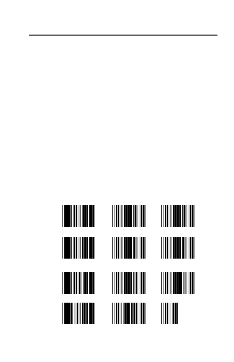
This numeric "Barpad" illustrates Accumulate Mode. Scan 5, 3, 8, and Enter.
The reader transmits a single message of 538.
7 8 9
4 5 6
1 2 3
0 Clear Buffer Enter
23
Page 27

Function/Control Key Support
The RF Laser can also transmit key sequences for function, control, alt
(command and option keys on Macs), cursor and shift keys, for ease of use
with the many software packages using these keys for menus or commands.
You can include these codes in other bar codes, or you can scan these
“keystrokes” into your Preamble or Postamble in order to add them to every
scan from your reader. You must have Full ASCII Code 39 enabled on your
reader (this is the default setting). Scan the corresponding bar code (or pairs of
codes for Pg Up, Pg Dn, Home, etc) from the Full ASCII menu to emulate the
chosen key.
PC Key Full ASCII Menu Bar Code
F1 SOH (f1)
F2 STX (f2)
F3 ETX (f3)
F4 EOT (f4)
F5 ENQ (f5)
F6 ACK (f6)
F7 BEL (f7)
F8 SO (f8)
Numpad 5* Null 5
Enter CR
F9 SI (f9)
F10 DLE (f10)
Del Null .
Insert Null 0
Left Arrow* Null 4
Rt Arrow* Null 6
Dn Arrow* Null 2
Up Arrow* Null 8
Pg Up* Null 9
Pg Dn* Null 3
Home* Null 7
End* Null 1
Shift ON EM (Shift ON)
Shift OFF SUB (Shift OFF)
Control On FS (Ctrl ON)
Control Off GS (Ctrl OFF)
Alt On RS (Alt ON)
Alt Off US (Alt OFF)
* refers to the keys on the Number pad on the far right side of a PC keyboard.
To emulate any of the keys above, scan the appropriate bar code from the
FULL ASCII MENU. For example, to emulate the f5 key, scan the ENQ bar
code.
24
Page 28

Simply scan the correct bar code(s) from the FULL ASCII MENU. For
example, if the WDP reads the bar code SOH (ASCII 001 -- a control-A) from
the FULL ASCII MENU, it will transmit an F1 key.
Shift, Ctrl and Alt keys require three sequences:
1) The ON code generated when the Shift, Ctrl or Alt key is pressed.
2) The other key to be used in conjunction with the Shift, Ctrl or Alt key.
3) OFF code generated when the Shift, Ctrl or Alt key is released.
(For example, to create a Control C bar code: use Control ON, C, and Control
OFF. To put Control C in a Preamble or Postamble, scan from the Full ASCII
Menu: Control ON, C, and Control OFF).
Function keys F11 and F12
Function keys F11 and F12 require two bar codes to be scanned to make these
functions keys. The F11 key is created by combining the Null and SOH. The
F12 key is created by combining the Null and the STX.
Windows Key
The Windows key on a Windows keyboard is transmitted by scanning 4 bar
codes - NULL and C for Windows On (pressing down) and NULL and D for
Windows Off (releasing the key).
Command and Option Keys on Mac USB Keyboards
When you have a WDP Reader attached to a Macintosh Computer's USB port,
to emulate the Command key, use the Windows key ON/OFF bar codes
NULL, C (Command ON) and NULL, D (Command OFF) For the Option Key
ON/OFF use RS (Option On) and US (Option Off).
Transmitting any ASCII character using its 3-digit ASCII code
You can also transmit any ASCII character from 000 to 255 by emulating the
PC technique of typing a character's ASCII number on the numeric pad while
holding down the Alt key. For example, to transmit ASCII 250, you would
scan the bar codes for:
Keystroke
Full ASCII Menu
Bar Code
Alt ON RS
Ins (0 on the numeric pad) DC2
Down Arrow (2 on the numeric pad) NAK
Numpad 5 LF
Ins (0 on the numeric pad DC2
Alt OFF US
25
Page 29

Troubleshooting
All Models Troubleshooting
The beam won’t stay on, or I just get a narrow beam when I pull the trigger,
or The scanner won’t turn on when I pull the trigger and I get 3 beeps
• All of the above problems are an indication that your BATTERIES ARE
TOO LOW. With any of the above symptoms, recharge the battery in the
RF Laser before assuming you have some other kind of problem.
The reader won't beep when reading bar codes
• Recheck all the connections. Get close to the Base Station. Try reading
the Link Test bar code, following the steps for scanning on page 8.
• If you hear two beeps, but see nothing on the screen, and you are
reading the pocket card, you must read the ENTER bar code to have
anything transmitted. Any Code 39 or 128 bar code with leading spaces
(such as the Barpad on page 23) will not be transmitted to your
computer until you read a bar code without a leading space. Try
reading the Test Label on page 21 as an example of a known good label
without a leading space. If you have bar codes with leading spaces in
them, and you want them transmitted, you must disable Accumulate
Mode using the Setup Menu.
• Reread the configuration section and make sure you properly enabled
the bar code types you're trying to read.
Extra characters at the beginning or end of your bar code data
• Clear the Preamble and Postamble.
Poor read rate
• Get close to the Base Station and try reading the test label on page 21
(following the scanning instructions on page 8) as an example of a
known good bar code. Examine your bar codes to make sure they have
dark bars, clearly defined bars and white spaces, and a "quiet zone" of
at least 1/4 inch to the left and right. If the bars are gray, or so dark that
they "bleed" into the white spaces, the person or organization printing
them will need to adjust the printer or get a new ribbon or toner
cartridge for it.
I get six beeps when the RF Laser powers up or six flashes or the Base
Station flashes and turns Red or Orange.
• The unit needs repair. Call for an RMA.
The Orange light stays on the RF Laser Scanner
• You are in Setup Mode. Scan End Setup on the RF Laser Setup Menu.
26
Page 30

USB Trouble Shooting
The Base Station's light flashes in Red cycles when the USB cable is
connected.
• The Base Station cannot enumerate. The driver is probably not
installed correctly.
Occasionally the user will be unaware that he aborted his driver
installation. Once the process has started, it should finish
successfully. If it doesn’t, you will not see any data on the screen
when scanning.
To resolve a driver installation problem follow the applicable
instructions below:
Windows XP:
1. Go to the Start menu.
2. Select Control Panel.
3. Switch to "Classic View" if in "Category View"
4. Select "System".
5. Select "Hardware" tab.
6. Select "Device Manager"
7. Double Click on the" Human Interface Devices"
8. Locate the USB Human Interface Device with a "!" in the icon.
9. Click on Update Driver
10. Follow instructions. If XP fails to find the driver on the
computer's hard disk, you may have to insert and point to the
original Windows XP CD to complete the installation.
11. Click "Finish"
Win98/ME:
1. Go to the "Start" menu.
2. Go to "Settings".
3. Select "Control Panel".
4. Go to "System".
5. Click on the "Device Manager" tab.
6. Double Click on the "USB Human Interface Devices" (it may be
titled TriCoder HID Keyboard instead).
7. Now click on the "Reinstall Driver" button.
8. Follow directions. If the installer cannot find the right driver file
on your hard disk, you may have to insert the original Windows
98 CD and point to it to complete the installation.
9. Click "Finish".
27
Page 31

Win2000:
1. Log on as Administrator and open the “Administrative Tools”
folder in your Control Panel.
2. Run the “Computer Management” utility.
3. Select the “Tree” tab on the left panel
4. Find the “Device Manager” entry under “System Tools” and click
on it. The right panel will display current devices.
5. Problem devices will be identified with an “!” icon. Find either
the “HID Keyboard Device” under Keyboards or the “USB
Human Interface Device” under Human Interface Devices and
double-click on one of those entries.
6. Now select the “Driver” tab at the top of the window and click
on the “Update Driver” button. Follow the prompts to re-install
the HID driver.
Serial Troubleshooting
The reader beeps on reads, but nothing appears on your screen using
PortKey OR nothing appears to your own software.
• Recheck the installation instructions beginning on page 4 to make sure
all cables are properly connected.
• If you're trying to read Code 39 bar codes with leading spaces (such as
the Barpad on page 23) and have enabled Accumulate Mode, those bar
codes will not be transmitted to your computer until you read a bar
code without a leading space. Try reading the Test Label on page 21 as
an example of a known good label.
• If you're using PortKey on an IBM-compatible, verify that the readers
matches the program's COM port, baud rate, data bits, stop bits, and parity
• If you're using your own software to read the serial port, verify that the
problem is not in your software. Run the WDR Serial Test Program
that shipped with your reader and see if it gets any data on the screen
when you read a bar code.
• Use a "null modem" connector to test switching pins 2 and 3 on one or
more serial cables, or use a breakout box to modify your cable(s).
The reader doesn't beep when you try to read your bar codes.
• Make sure the power adapter is plugged in.
• Try reading a known good bar code -- the Test Label on page 21,
following the steps for proper scanning technique on page 8.
• Read the instructions beginning on page 7 on configuring the Reader
for different bar code types and formats, and make sure you properly
enabled the bar code types you're trying to read.
28
Page 32

Data characters are garbled or missing.
• Make sure you've set the reader to the same baud rate, parity, data bits
and stop bits as your serial port.
• If Code 39 bar codes are transmitting in the wrong case (upper and
lower transposed), set Caps Lock Off on the Setup Menu.
• If you're getting occasional extraneous characters, try cutting the
jumper between pins 8/20 in the serial Y-Cable's DB25 connectors. See
page 6.
29
Page 33
Appendix A
Changing Jumpers and Channels
You may want to change the channel on the Base Station or you may want to
set the unit to use a Serial Y Cable. To do so, open up the case.
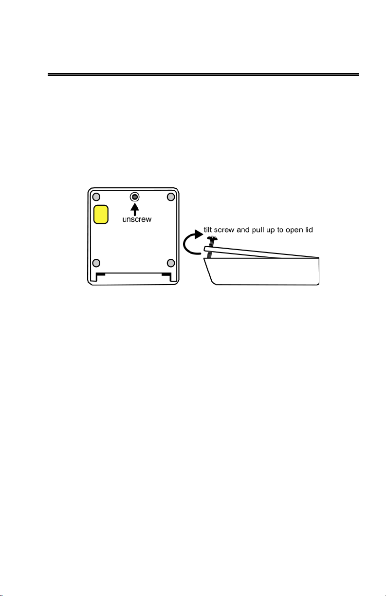
Turn your Base unit upside-down and unscrew its single Phillips screw. If you
don't completely remove the screw you can use it as a lever to pull up on the
cover, otherwise insert a fingernail, credit card edge or small screwdriver
blade into the gap between the base and side of the case. Gently use it as a
lever to lift up the edge of the base, then grasp the edge of the base and open it
outward like a door.
This exposes the reader's circuit board, as shown on the next page. When
you've finished examining or changing jumper settings, put the reader case
back together by reversing the steps illustrated on this page.
To change the Channel (0-9 for USA and Canada), unplug the power supply
and use a small flat head screwdriver to move the rotary switch shown below
to the number of the channel you desire. Now simply put the case back
together and plug in the power supply. You should see channel number set+ 3
green flashes on the base's LED; i.e. channel 0 setting will flash 3 times -channel 6 setting will flash 9 times.
29
Page 34
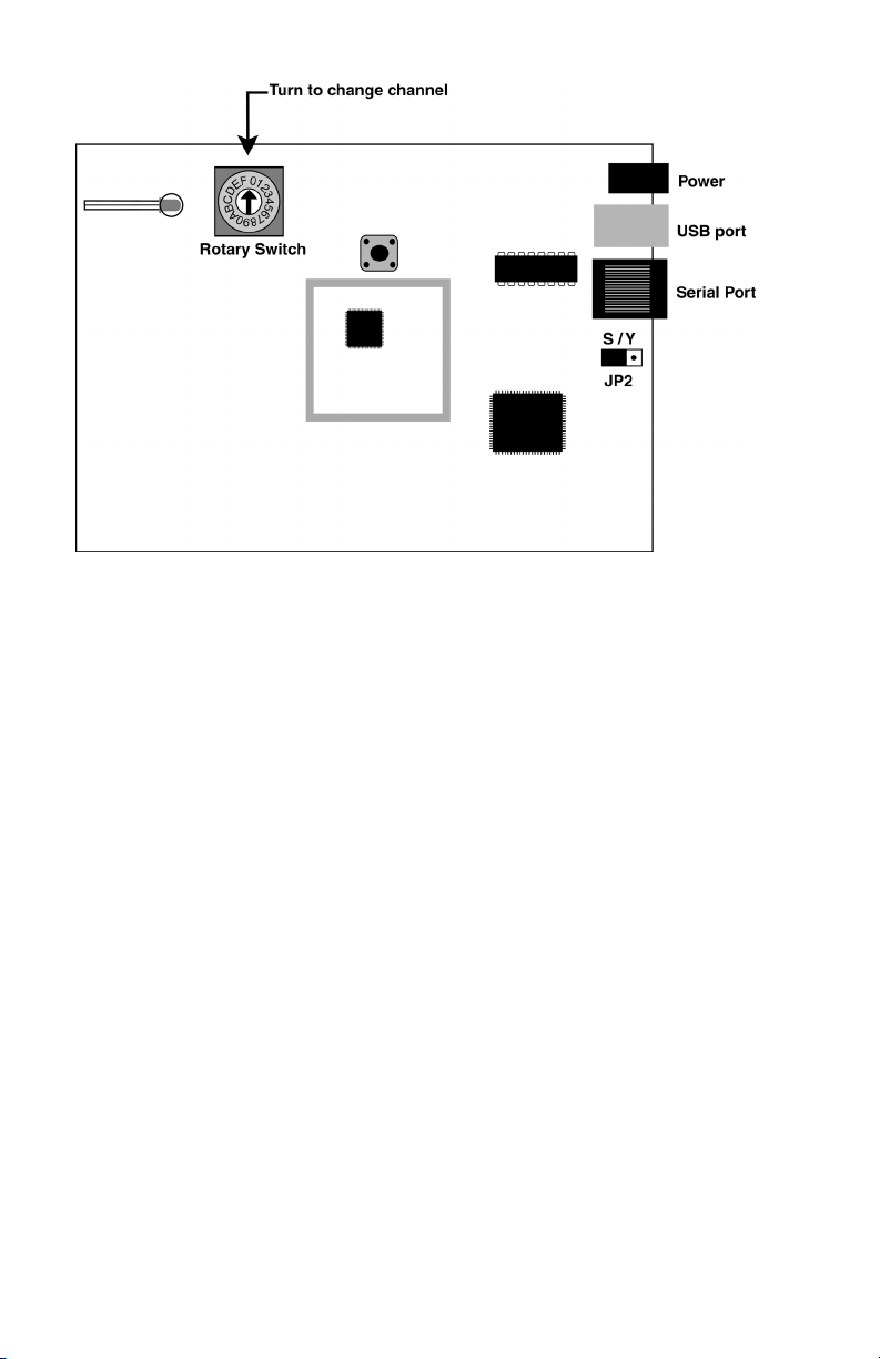
Serial Users, if you are going to use the Serial Y Cable (F45-1), you will need
to change the JP2 (Jumper 2) from S to Y. This permits Half Duplex
transmissions and interface between a host and terminal.
30
Page 35
Appendix B
Recharging the Batteries
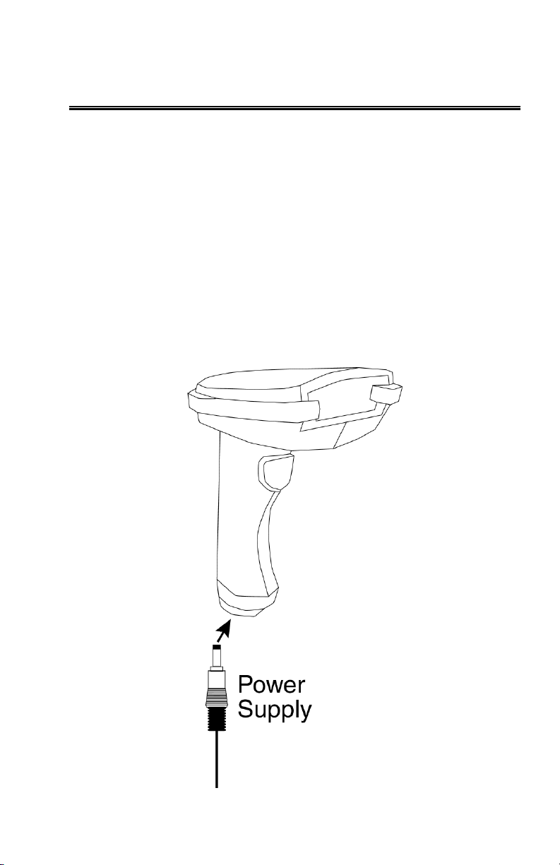
The LZ400-RF Laser has a rechargeable lithium ion battery built-in.
When not in use, the RF Laser should be plugged into the supplied, regulated
Worth Data 5V power adapter (DO NOT USE ANY Supply Except Worth
Data), so that it will always be recharged. The built-in recharger is a smart
charger, so you can't overcharge the battery and ruin it. A full charge takes
about 3 hours.
If you ordered the USB interface, the F10 power supply included with the laser
is used for recharging, since USB does not usually require the power supply to
power the Base Station (see page 6). The serial configuration will require a
second Worth Data 5v power supply if you want to keep the Base Station
powered up at all times. You can get by with one power supply by simply
unplugging the Base Station so you can recharge the RF Laser Reader.
31
Page 36

Appendix C
Specifications for Code 39
Code 39 (or Code 3 of 9) is the de facto standard of non-retail American
industry. It is widely used in the automotive industry (AIAG specifications) as
well as in government and military applications (LOGMARS specifications).
Code 39 is flexible, features a large character set, variable data length and
density, and bi-directional readability. Code 39 is extremely accurate;
substitution errors are almost nonexistent. Its character set consists of
numbers 0 through 9, upper case A-Z, and characters Space, $, %. / + and -.
The name "Code 39" comes from both the fact that its
character set originally contained 39 characters (it now
has 43) and from its structure. Each character is formed of
three wide and six narrow elements, made up of five bars
and four spaces. Code 39's density can vary from a low
*C39*
Code 39 uses an asterisk (*) as a start and stop character. This character must
precede and follow the data in the bar code. The RF Laser Reader gives you
the option of transmitting or not transmitting these characters when the bar
code is read.
Exact specifications for Code 39 and other bar code symbologies can be
obtained from ANSI at the address below:
Code 39 has several advanced features and functions that are discussed further
in this appendix.
of .75 characters per inch (cpi) to a high of 9.4 cpi.
There should be a ¼" "quiet zone" (white space) to
the left and right of the bar code.
American National Standards Institute
Customer Service
11 West 42
New York, NY 10036
212-642-4900
http://www.ansi.org
document ANSI/AIM BC1-1995
nd
St., 13th Floor
32
Page 37
Code 39 Advanced Features and Functions
Mod 43 Check Character
Standard Code 39 can be printed with a "Mod 43 Check Character". This
Mod 43 check character cannot be used with Full ASCII Code 39. The check
character is derived by assigning a value to each character in the data to be bar
coded from the table as follows:
Char value Char value Char value Char value
0 0 B 11 M 22 X 33
1 1 C 12 N 23 Y 34
2 2 D 13 O 24 Z 35
3 3 E 14 P 25 - 36
4 4 F 15 Q 26 . 37
5 5 G 16 R 27
6 6 H 17 S 28 $ 39
7 7 I 18 T 29 / 40
8 8 J 19 U 30 + 41
9 9 K 20 V 31 % 42
A 10 L 21 W 32
Table C-1. Mod 43 Check character calculation for Code 39
Here is an example to illustrate how the check character is calculated for bar
code data of 123XYZ:
1. Take the sum of the values assigned to each character:
1 + 2 + 3 + 33 + 34 + 35 = 108
1 2 3 X Y Z
2. Divide the sum by 43: (thus the name modulus 43)
space
38
108/43 = 2 with a Remainder of 22
3. Find the character corresponding with the remainder.
M (value 22) is the CHECK CHARACTER
The data becomes 123XYZM, with M added as the Mod-43 check character.
33
Page 38

Full ASCII Extension to Code 39
"Full-ASCII Code 39" expands the Code 39 character set to include all 128
ASCII characters. Symbols 0-9, A-Z and punctuation characters. and - are
identical to their Code 39 representations. Lower-case letters, additional
punctuation characters and control characters are represented by sequences of
two Code 39 characters.
This table depicts the Full ASCII character set as a function of Code 39 characters:
ASCII Code 39 ASCII Code 39 ASCII Code 39 ASCII Code 39
NUL %U SP Space @ %V ‘ %W
SOH $A ! /A A A a +A
STX $B “ /B B B b +B
ETX $C # /C C C c +C
EOT $D $ /D D D d +D
ENQ $E % /E E E e +E
ACK $F & /F F F f +F
BEL $G ‘ /G G G g +G
BS $H ( /H H H h +H
HT $I ) /I I I i +I
LF $J * /J J J j +J
VT $K + /K K K k +K
FF $L , /L L L l +L
CR* $M - - M M m +M
SO $N . . N N n +N
SI $O / /O O O o +O
DLE $P 0 0 P P p +P
DC1 $Q 1 1 Q Q q +Q
DC2 $R 2 2 R R r +R
DC3 $S 3 3 S S s +S
DC4 $T 4 4 T T t +T
NAK $U 5 5 U U u +U
SYN $V 6 6 V V v +V
ETB $W 7 7 W W w +W
CAN $X 8 8 X X x +X
EM $Y 9 9 Y Y y +Y
SUB $Z : /Z Z Z z +Z
ESC %A ; %F [ %K { %P
FS %B < %G \ %L | %Q
GS %C = %H ] %M } %R
RS %D > %I ^ %N ~ %S
US %E ? %J _ %O DEL %T, %X
Table C-2. Full ASCII Table
34
Page 39

Appendix D
Code 93 Specifications
Code 93 is variable length, continuous, bi-directional, compact code. Code 93
is an alphanumeric bar code, which consists of 43 data characters (0-9,A-Z,
$/+%.- and Space), 4 control characters, and a unique start/stop character.
The entire set of 128 ASCII characters is represented in Code 93 using
combinations of control characters and data characters.
The control characters are
pairing these control characters with normal data characters. It is almost identical
to the pairings for Code 39; Code 39 uses $M to produce a Carriage Return
(ASCII 13) character -- Code 93 uses
Code 93's two built-in check digits greatly minimize the possibility of reader
substitution errors. These check digits are never transmitted by the bar code
reader. Code 93's Start and Stop characters are also never transmitted.
If you have not decided which bar code type to use for your application and
are considering using Code 93, while we agree that Code 93 is an excellent
code, we believe that Code 128 is generally preferable because:
1. Code 93 does not have the numeric compression capability that
128 does, and
2. Code 93 requires pairings to make all Full ASCII characters while
128 does not.
, , , and . Full ASCII 93 is created by
M to produce the Carriage Return.
35
Page 40

Appendix E
Codabar Specifications
Codabar is widely used in libraries, blood banks, the cotton industry and
transportation industries. Its' character set consists of numbers 0 through 9,
and punctuation characters + . - / : and $. Symbols a, b, c, d, t, n, * and e are
used as start and stop characters. Characters are constructed of four bars and
three spaces.
Codabar is a numeric-only code, but different
combinations of start and stop characters can be used to
identify different types of labels. Codabar's variable
data length and extremely low error rate make for a
a12345b
Codabar start/stop transmission
The Codabar section on the RF Laser Reader Setup Menu lets you determine
whether Codabar start/stop characters are transmitted or not. If you are
varying start/stop characters with different types of labels, you'll want to
"Enable Stop/Start character Transmission". Start/stop character
transmission can also be helpful if you want your program to differentiate
between data coming from the RF Laser Reader and data coming from the
keyboard. If neither situation applies, you'll probably want to disable it.
versatile bar code.
36
Page 41

Appendix F
Code 128 Specifications
Code 128 is a very powerful bar code, combining an extensive character set
and variable length with compactness and error checking. The character set
contains all 128 ASCII characters with each character made up of three bars
and three spaces. Each element (bar or space) varies from one to four units in
width, totaling 11 units of width per character. Code 128 contains two levels
of error checking:
• Each character is checked for internal parity, and
• The last character is a checksum.
Code 128 has three subsets, A, B and C. Subset A
contains alphanumeric characters and unprintable
control characters, subset B contains alphanumeric
characters plus printable control characters and subset C
12345
is not displayed by the bar code reader. Code 128 bar codes can be made up of
only one subset or may be a combination of several.
The Code 39 features of Accumulate Mode, Caps Lock ON and Caps lock
OFF also apply to Code 128.
contains only numeric characters and uses a 2-character
encoding scheme to create a more compact bar code.
Code 128 uses an internal Mod 103 check character that
UCC-128/ EAN-128
UCC-128/EAN-128 Code is a subset of Code 128 adopted by the UCC and
EAN council’s for use as a shipping label symbology. UCC/EAN-128 bar
codes always start with a Function Code 1 character. In addition, all variable
length fields are terminated by a Function Code 1 character unless they are the
last field in the bar code.
The RF Laser Reader outputs the following for the special function codes and
start sequences:
]C1 Start C/Function Code 1
^] (GS) Function Code 1 as a variable string terminator
If UCC/EAN 128 is enabled, the reader looks for the Start C/Function Code 1
to indicate a UCC/EAN 128 bar code.
The UCC Serial Shipping Container Code specification calls for a 19 digit
UCC/EAN 128 code with an additional Mod 10 Check digit (20 digits in all).
37
Page 42
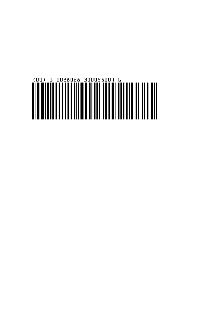
The Mod 10 Check digit is calculated the same as the Interleaved 2 of 5
example in Appendix G. It is the data length as well as the MOD 10 check
digit that distinguishes the UCC Serial Shipping Container Code from other
UCC /EAN 128 bar codes.
UCC/EAN 128 is enabled by scanning the appropriate bar codes on the RF
Laser Reader Setup Menu. If UCC/EAN 128 is enabled, you will be able to
read both standard Code 128 bar codes as well as the UCC/EAN 128 bar codes
with the Function 1 character and the Mod 10 check character.
UCC 128 Shipping Container Code
The UCC 128 specification is used extensively by the retail industry. If you
have a requirement for a UCC 128 Serial Shipping Container bar code, be
sure to follow the specification as closely as possible as many vendors will
impose fines for non-conformance. For more information on UCC/EAN 128,
contact GS1 US at:
GS1 US
7887 Washington Village Drive, Suite 300
Dayton, OH 45459
937-435-3870
937-435-7317
[email protected]
8:00 a.m. to 6 p.m. EST
Many of the specifications are available online at:
http://www.uc-council.org
38
Page 43

Appendix G
Interleaved 2 of 5 Code
Interleaved 2 of 5 Code is a numeric-only, even-number-of-digits bar code. It is
widely used in warehouse and industrial applications. A combination of five
elements, two wide and three narrow represent each character. Odd-number
position digits are encoded in the bars, even-number positions in the spaces.
Interleaved 2 of 5 Code is so susceptible to partial scans being
interpreted as valid reads that we recommend at least one of the
following safeguards:
123456
• Use one length of I 2 of 5 code. Using one length of data allows
• Use a check digit. Worth Data’s LabelRIGHT printing program
you to tell the RF Laser Reader to look for one length of I 2 of 5
code only. By default, the RF Laser Reader is set to look for a 6
digit I 2 of 5 code but you can set the length to something different
using the RF Laser Reader Setup Menu. Setting the length to 00
digits allows variable length bar codes scanning but also
dramatically increases your chance of a mis-read.
automatically calculates and prints a check digit upon request using
the method below:
Interleaved 2 of 5 Mod 10 check digit calculation
1. Assume that the bar code data is 1987.
2. Starting with the least significant digit (in this case, a 7), label the
digits alternatively even and odd.
7 - even
8 - odd
9 - even
1 – odd
3. Take the sum of the odd digits:
8 + 1 = 9
4. Multiply the sum of the even digits by 3:
(7 + 9) x 3 = 48
5. Add the results of steps 3 and 4:
9 + 48 = 57
39
Page 44

6. Subtract the result of step 5 from the next highest multiple of 10:
60 - 57 = 3
7. The checksum becomes the low-order digit:
19873
8. Because the data now has an odd length, a leading zero is added,
for the final result of
019873
40
Page 45

Appendix H
UPC Specifications
UPC symbols are found on almost all grocery
products and many other retail items. The UPC
code most people are familiar with (UPC-A) is a
fixed-length (12 digits) numeric only code, with
the first digit controlled by UPC coding
assignments and the last digit a checksum. UPC-
E and UPC-E1 are variations of the standard
UPC-A code. Each digit is constructed of two bars and two spaces. UPC has
very precise standards of code size, structure, and numbers to be used.
The exact UPC/EAN symbol specifications are available from:
Specifications are also available via the Internet at:
http://www.uc-council.org
Keep the following guidelines in mind when printing UPC bar codes:
• If you plan to use a "supermarket-type" in-counter scanner to read
the codes, specify a bar code height of at least .9" for an optimal first
read rate.
• Make it an early practice to observe the numbering conventions of
the GS1 US. Do not label unmarked merchandise with a bar code
whose numbers may conflict with those already assigned. If products
with these numbers are not in your store now, they are likely to be in
the future, causing conflicts in your inventory system.
EAN is an international superset of UPC. EAN-13 has
13 digits, with the first two digits representing a
country code. The final digit is, as with UPC, a check
digit. EAN-8 is a shorter version on the EAN-13 code
containing seven data digits and ending again with a
checksum.
GS1 US
7887 Washington Village Drive, Suite 300
Dayton, OH 45459
937-435-3870
937-435-7317
[email protected]
8:00 a.m. to 6 p.m. EST
41
Page 46
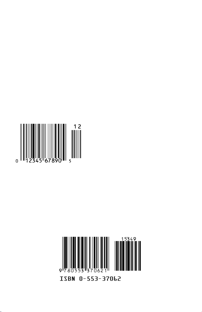
• The leading Number System Character, (the first number of the 11
digits to be entered) should conform to these UPC assignments:
0,6,7,8 Regular UPC 12 digit codes with numbers assigned by
the GS1 US. (Do not use 0 as the leading number for instore marking).
2 Store-marked random weight items of meat and produce.
3 Reserved for National Drug Code and Health Related Items.
4 Use this leading digit for in-store marking of non-food items.
5 Reserved for coupons. Do not use this today, or you will not
be able to process coupons through your system tomorrow.
UPC 2 and 5-character supplemental codes
The UPC standards include the addition of a
2 or 5-character supplemental code used
with magazines and paperback books. To
read the supplements, you must first enable
them using the RF Laser Setup Menu.
NOTE: Enabling the supplements disallows
the reading of UPC codes from right to left
to assure that the supplement does not get missed.
ISBN Specifications
ISBN (International Standard Book Numbering) bar codes are essentially
EAN-13 with a 5-digit supplement, where the first 3 digits are the Bookland
country codes of 978 for books and 977 for periodicals. Although the bar code
contains 18 characters, the ISBN format uses only 9 of them, along with a
newly calculated Mod-11 check digit. For example, a bar code containing the
numbers 978055337062153495 would transmit as 0553370626 in the ISBN
format. The RF Laser Reader has the option of transmitting in the ISBN
format.
42
Page 47

ISBN specifications are available from:
American National Standards Institute (ANSI)
11 West 42nd Street, 13th Fl.
New York, New York 10036
Tel. 212.642.4900
www.ansi.org
document ISO 2108:1992
The UPC/EAN checksum character
The last character in a UPC-A, UPC-E, UPC-E1, EAN-13 or EAN-8 bar code
is the checksum. For reference, these are the methods of calculation:
Checksum calculation for UPC-A, EAN-13 and EAN-8
Use Worth Data’s phone number (it's not a real UPC-A code) as sample data:
18314589938
Assign even and odd positions, starting at the right and moving left:
8 3 9 9 8 5 4 1 3 8 1
odd even odd even odd even odd even odd even odd
1. Starting with the leading digit, 8, take the sum of all the characters in
the odd positions.
2. Multiply the result of step 1 by 3.
3. Now take the sum of all the even-position characters.
4. Add the result in Step 2 to the result in Step 3.
5. Subtract the result from the next higher multiple of 10.
Next higher multiple of 10 over 125 = 130
5 is the Modulo-10 check character. The data to be printed
This same formula is used for EAN-13 (using the 1-12 digits) and EAN-8
(using the 1-7 digits).
8 + 9 +8 + 4 + 3 + 1 = 33
33 x 3 = 99
3 + 9 + 5 + 1 + 8 = 26
99 + 26 = 125
130 - 125 = 5
becomes:
183145899385.
43
Page 48

UPC-E Checksum Calculation
Use the sample data of 123456 to demonstrate the UPC-E checksum
calculation:
1. The 6 digit UPC-E code is converted to a 10-digit code, using an
expansion scheme based on the sixth digit:
If the code
ends in:
0
1
2
3
4
5
6
7
8
9
Because the sample UPC-E code ends in a 6, the insertion digits 0000 are
inserted at the sixth digit (insertion position 6):
2. Add the Number System Character of 0 to the sample data:
3. Use the UPC-A check digit calculation described in the previous
section to produce a check digit as if it were a UPC-A code. The
check digit for the sample data is:
4. The complete 8 digit code consists of the Number System Character,
the original 6 digit code and the check digit:
UPC-E Data Insertion Digits Insertion
abcde0 00000
abcde1 10000
abcde2 20000
abcde3 00000
abcde4 00000
abcde5 0000
abcde6 0000
abcde7 0000
abcde8 0000
abcde9 0000
Position
3
3
3
4
5
6
6
6
6
6
1234500006
01234500006
5
01234565
10 digit code
Ab00000cde
Ab10000cde
Ab20000cde
Abc00000de
Abcd00000e
Abcde00005
Abcde00006
Abcde00007
Abcde00008
Abcde00009
44
Page 49

Appendix I
MSI/Plessey Specifications
Plessey is a variable length numeric only bar code. MSI Bar Code is a
variable length, numeric-only code with an automatically appended Modulus
10 check digit. MSI is sometimes called Modified Plessey Code. If the user
specifies an additional check digit, the MSI code can be 14 digits long,
otherwise it has a maximum length of 13 characters. This is how the MSI
check digit(s) are calculated:
The MSI Mod 10 check digit is calculated as follows:
The example bar code data is:
1. Form a number from the odd positions, starting in the units position.
2. Multiply the new number by 2
3. Add the digits of product
4. Add the even digits of the original number to the result in 3
5. Subtract the result from the next highest multiple of 10
6. New Check Digit
7. Data with check digit is:
82345
835
(835) x 2 = 1670
1 + 6 + 7 + 0 = 14
2 + 4 + 14 = 20
20 - 20 = 0
0
823450
45
Page 50

The MSI Mod 11 check digit is calculated as follows:
The example bar code data is:
943457842
1. Assign a checking factor to each number, starting with the units
position of the number (in this example, the 2) up to the highest
order position (the 9). Use checking factors of:
2,3,4,5,6,7,2,3,4,5,6,7...
2. Multiply the checking factor with its assigned number and add the
products:
4 + 12 + 32 + 35 + 30 + 28 + 6 + 12 + 36 = 195
3. Divide the sum by 11
195/11 = 17 remainder 8
4. Subtract remainder from 11
11 - 8 = 3
5. New Check Digit
3
(If the remainder is 10, no check digit is added.)
6. Data with check digit is:
9434578
46
Page 51

47
Appendix J
RF Laser Setup Menu
To change a setting using the RF Laser Setup Menu:
• Scan START SETUP to enter setup mode
• Scan the parameter you want to change (i.e. Code 3 of 9)
• Choose the setting you want to change and scan the corresponding letter or
number from the Barpad Table (0-9, A-F)
• When all changes have been made, scan END SETUP
• For Preamble and Postamble settings, use the FULL ASCII MENU
• * indicates default settings
Start Setup End Setup
*/+/*
*/-/*
Channel
Scan 0-9 to select channel
*/0/*
Aiming Dot Duration
Scan 2 digits from 00 to 99 (9.9 seconds) to
set aiming dot duration.
*/K/*
Link Test Code
Test RF Transmission without
tramsmitting data.
*--*
Preamble Postamble
*/1/*
*/2/*
Scan up to 15 characters from the Full
ASCII Menu. Scan SET when completed.
Scan up to 15 characters from the Full ASCII
Menu. Scan SET when completed.
Terminator Character Characters
0 Enter
1 None
2Tab
*/H/*
*.1.*
Scan up to 8 sets of hex characters to
reassign and delete characters in the bar
code output. Scan SET when completed.
*
RF Laser Setup
Page 52

48
Start Setup End Setup
*/+/*
*/-/*
Code 3 of 9 UPC/EAN
*/A/* */B/*
0 Enable Code 39
1 Disable Code 39
2 Enable Full ASCII Code 39
3 Disable Full ASCII Code 39
4 Enable Accumulate Mode
5 Disable Accumulate Mode
6 Transmit Start/Stop characters
7 Don’t transmit Start/Stop characters
8 Enable Mod 43 Check Character
9 Disable Mod 43 Check Character
A Transmit Mod 43 Check Character
B Don’t transmit Mod 43 Check
Character
C Caps Lock ON
D Caps Lock OFF
0 Enable UPC/EAN
1 Disable UPC/EAN
2 Enable Supplements
3 Disable Supplements
4 Transmit UPC-A NSC
5 Don’t transmit UPC-A NSC
6 Transmit UPC-A Check Digit
7 Don’t transmit UPC-A Check Digit
8 Transmit UPC-E NSC & EAN-8 Flag Ch
9 Don’t transmit UPC-E NSC & EAN-8
Flag Ch
A Transmit UPC-E & EAN-8 Check digit
B Don’t transmit UPC-E & EAN-8
Check digit
C UPC-E Compressed transmission
D UPC-E Expanded transmission
E EAN-8 observes 9 & A above
F EAN-8 is forced to transmit 8 digits always
*
*
*
*
*
*
*
*
*
*
*
*
*
*
*
2 of 5 Code 2 of 5 Length
*/C/*
0 Enable I 2 of 5
1 Disable I 2 of 5
2 Enable check digit
3 Disable check digit
4 Transmit check digit
5 Don’t transmit check digit
6 Enable 2 of 5
7 Disable 2 of 5
*
*
*
*
*/5/*
Scan 2 digit length (default is 06)
RSS-14
0 Disable RSS-14 2 14 + Identifiers
1 Standard 14 digits 3 14 + UCC-128 Emul.
*/%/*
Codabar MSI/Plessey
0 Disable MSI
1 Enable MSI 1 Mod 10 check digit
2 Enable MSI 2 Mod 10 check digits
3 Enable MSI Mod 11/10 check digits
4 Transmit no check digit
5 Transmit 1 check digit
6 Transmit 2 check digits
7 Enable Plessey
8 Enable Labelcode 5
9 Enable Labelcode 4
*/R/*
*
*
*/D/*
0 Enable Codabar
1 Disable Codabar
2 Enable CLSI Codabar
3 Disable CLSI Codabar
4 Suppress start/stop characters
5 Enable start/stop characters
*
*
*
RF Laser Setup (cont.)
*
Page 53

49
Start Setup End Setup
*/+/*
*/-/*
BARPAD TABLE
08
*0*
19
*1*
2A
*2*
3B
4C
5D
6E
7F
*3*
*4*
*5*
*6*
*7*
*8*
*9*
*A*
*B*
*C*
*D*
*E*
*F*
Code 93 Code 128
*/S/*
0 Disable 128
1 Enable 128
2 Disable UCC/EAN-128
3 Enable UCC/EAN-128
*
*
0 Enable Code 93
1 Disable Code 93
2 Enable Full ASCII Code 93
3 Disable Full ASCII Code 93
*/W/*
*
*
SET
CLEAR
*/$/*
*/./*
Clears Preamble & Postamble and
resets current individual parameter
back to default settings.
RESET
*///*
Warning: Scanning this bar code
after scanning START SETUP will
reset the reader back to all of the
default parameter settings.
RF Laser Setup (cont.)
Page 54
50
RF Base Station Setup Menu
This menu applies only to the setup for a Serial RF Base Station.
Start Setup (FOR BASE ONLY) End Setup
*.+.*
*/-/*
Baud Rate
4) 4800
5) 9600
6) 19,200
7) 38,400
*/F/*
Data Bits
0) 7 bits
1) 8 bits
*/I/*
Stop Bits
0) 1 bit
1) 2 bits
*/J/*
Parity
0) None
1) Even
2) Odd
*/G/*
Protocol
0) None
1) Host Controlled acknowledge-serial only
*/E/*
BARPAD TABLE
0 8
*0*
1 9
*1*
2 A
*2*
3 B
4 C
5 D
6 E
7 F
*3*
*4*
*5*
*6*
*7*
*8*
*9*
*A*
*B*
*C*
*D*
*E*
*F*
CLEAR
*/./*
Resets current individual parameter
back to default settings.
RESET
*///*
Warning: Scanning this bar code after
scanning START SETUP will reset the
RF Base Station back to all of the
default parameter settings.
*
*
*
*
*
Page 55

51
Full ASCII Menu
NUL SOH(f1) STX(f2) ETX(f3)
*%U*
*$A*
*$B* *$C*
000 00 001 01 002 02 003 03
EOT(f4) ENQ(f5) ACK(f6) BEL(f7)
*$D*
*$E*
*$F*
*$G*
004 04 005 05 006 06 007 07
BS TAB LF VT(Pg Up)
*$H*
*$I* *$J* *$K*
008 08 009 09 010 0A 011 0B
FF(Pg Dn) CR SO(f8) SI(f9)
*$L* *$M* *$N* *$O*
012 0C 013 0D 014 0E 015 0F
DLE(f10) DC1(Del) DC2(Ins) DC3( )
➝
*$P*
*$Q* *$R* *$S*
016 10 017 11 018 12 019 13
DC4(➝) NAK( ) SYN( ) ETB(Home)
➝
➝
*$T* *$U* *$V* *$W*
020 14 021 15 022 16 023 17
CAN(End) EM(Shift On) SUB(Shift Off) Esc
*$X* *$Y* *$Z* *%A*
024 18 025 19 026 1A 027 1B
FS(Ctrl On) GS(Ctrl Off) RS(Alt On) US(Alt Off)
*%B* *%C* *%D* *%E*
028 1C 029 1D 030 1E 031 1F
SP ! “ #
*¯* */A* */B* */C*
032 20 033 21 034 22 035 23
$% & ‘
*/D* */E* */F* */G*
036 24 037 25 038 26 039 27
() * +
*/H* */I* */J* */K*
040 28 041 29 042 2A 043 2B
,- . /
*/L*
*-*
*.*
*/O*
044 2C 045 2D 046 2E 047 2F
01 2 3
*0*
*1* *2* *3*
048 30 049 31 050 32 051 33
45 6 7
*4* *5* *6* *7*
Char (function)
*%U*
BARCODE
052 34 053 35 054 36 055 37
Decimal Hex
Page 56

52
89 : ;
*8* *9* */Z* *%F*
056 38 057 39 058 3A 059 3B
<= > ?
*%G* *%H* *%I* *%J*
060 3C 061 3D 062 3E 063 3F
@A B C
*%V* *A* *B* *C*
064 40 065 41 066 42 067 43
DE F G
*D* *E* *F* *G*
068 44 069 45 070 46 071 47
HI J K
*H* *I* *J* *K*
072 48 073 49 074 4A 075 4B
LM N O
*L* *M* *N* *O*
076 4C 077 4D 078 4E 079 4F
PQ R S
*P* *Q* *R* *S*
080 50 081 51 082 52 083 53
TU V W
*T* *U* *V* *W*
084 54 085 55 086 56 087 57
XY Z [
*X* *Y* *Z* *%K*
\] ^ _
088 58 089 59 090 5A 091 5B
*%L* *%M* *%N* *%O*
092 5C 093 5D 094 5E 095 5F
`a b c
*%W* *+A* *+B* *+C*
096 60 097 61 098 62 099 63
de f g
*+D* *+E* *+F* *+G*
100 64 101 65 102 66 103 67
hi j k
*+H* *+I* *+J* *+K*
104 68 105 69 106 6A 107 6B
lm n o
*+L* *+M* *+N* *+O*
108 6C 109 6D 110 6E 111 6F
pq r s
*+P* *+Q* *+R* *+S*
112 70 113 71 114 72 115 73
Page 57

53
tu v w
*+T* *+U* *+V* *+W*
116 74 117 75 118 76 119 77
xy z {
*+X* *+Y* *+Z* *%P*
120 78 121 79 122 7A 123 7B
| } ~ DEL
*%Q* *%R* *%S* *%T*
124 7C 125 7D 126 7E 127 7F
Page 58

Index
2
2 of 5 Code........................................ 7
about........................................... 39
data length ..................................39
Data Length................................ 14
default settings ...........................13
8
8 beep pattern.................................... 2
A
Accumulate Mode ..............10, 22, 27
Acknowledge codes sent by host
computer.....................................19
Advanced Features/Functions ........33
AIAG ..............................................32
aiming dot enabling ........................17
ANSI information for Code 39....... 32
Automobile ID reading................... 18
Automobile VIN READING..........17
Automobile windshield reading .....18
B
Bar codes
Accumulate mode ...................... 22
character substitution .................16
default settings .............................7
Preambles and Postambles......... 14
trimming characters ................... 15
Battery recharging ..........................31
Baud rate......................................... 18
Beep patterns for RF Lasers ...........21
Beeping
and Accumulate Mode ...............22
during configuration ......................9
if your reader doesn't beep......... 25
six beeps upon boot up............... 25
Beeping in laser controlled by host
computer..................................... 19
bright light problems - aiming dot .17
C
Cable Pin-outs................................... 6
Cables require modification .............6
types .............................................6
Caps Lock .................................10, 28
Changing channels on Base............29
Changing the RF Laser channel .....10
Channel ...........................................10
Channel changes .............................29
Channel of RF Laser - default ........10
Character codes reassigning ...........16
Characters setup menu parameter...16
Check Character..............................33
Check digits/checksums .....................
......................33, 37, 38, 39, 43, 45
and Accumulate mode................22
Code 39.......................................10
Ingterleaved 2 of 5 .....................13
MSI Code ...................................13
UPC/EAN...................................11
Codabar...........................................36
CLSI Format............................... 13
default settings............................13
Start/stop Transmission..............13
Start/Stop transmission ..............36
Code 128 default settings ...............12
Code 128 Specifications................. 37
Code 128 subsets ............................37
Code 39 ........................................... 10
Accumulate mode.................10, 22
Caps Lock................................... 10
check digits...........................10, 33
start/stop transmission................ 10
Code 39 Advanced Features/Functions
....................................................33
Code 93 Specifications ...................35
COM port program .........................20
Command key on Mac USB...........24
Connecting in-line ............................6
Control keys emulation................... 23
D
Data bits ..........................................19
DB9 Straight Cable Pinouts..............6
Default settings .................................7
Delayed Transmission ....................17
Difficult Code 39 Reading.............. 18
DIFFICULT CODE SETUP
OPTIONS ...................................17
Double-scan checking.....................18
driver reinstallation......................... 26
Dual port serial cable pinouts........... 6
54
Page 59

E
EAN-128
Shipping Serial Container Code.12
Enabling
2 of 5 Code .................................13
Codabar.......................................13
Code 128.....................................12
Code 93.......................................14
MSI/Plessey................................13
UPC/EAN...................................11
Enabling and disabling features........9
Extended Coupon Code..................11
F
F34 Null Modem Cable Pinouts.......6
F36 DB9 Cable Pinouts ....................6
F45-1 Dual Serial Cable ...................6
Failed transmissions..........................2
Fixing substitution - laser read .......18
Full ASCII Code 39
about ...........................................34
default settings............................10
Full ASCII Extension to Code 39...34
Full ASCII hex values ....................16
Function Key emulation .................23
H
Hex values.......................................16
host and terminal interface .............30
How to use the setup menu...............9
I
Incorrect reading .............................18
Installation with dedicated
serial port......................................4
Installing the R/F Reader between a
computer and terminal.................. 5
Interleaved 2 of 5
check digit calculation................39
check digits.................................13
default settings............................13
Interleaved 2 of 5 Code...................39
Introduction.......................................1
ISBN Specifications........................42
L
Leading characters -- trimming ......15
Leading spaces - Accumulate
Mode.....................................22, 27
Link Test Code........... See Appendix J
lithium ion battery.............................1
LOGMARS .....................................32
M
Min/max limits on data ...................15
Modulus 43 Check Characters........33
MSI Code
check digit...................................13
default settings............................13
MSI/Plessey Specifications ............45
N
no data in USB ................................26
NSC assignments ............................42
Null Modem Cable F34, Pinouts ......6
Numeric "Barpad"...........................22
O
Opening the base station .................29
Operating Frequency USA................1
operational range.............................21
Orange light stays on ......................25
P
Parity ...............................................19
Plessey code ....................................45
PortKey installation ..........................4
Postamble ........................................15
Power adapters to fix
reader problems ..........................27
Preamble..........................................14
Problem solving ..............................25
Programming beeper on
laser scanner ...............................19
Protocol ...........................................19
Q
Quiet zones......................................17
R
Radio considerations.......................21
range................................................21
Reading through a windshield ........18
reading in sunlight with aiming dot17
Recharging the Batteries .................31
red led flashes on base ....................26
Reset................................................16
RF considerations............................21
RF Laser
beep pattern meanings ................21
colored light meanings ...............21
55
Page 60

components ..................................2
testing .........................................20
RF Laser default settings.................. 7
RS-232 pinouts .................................6
S
Scanner Beeps and LEDs .................2
Scanning techniques .........................8
scanning through a windshield....... 18
Selective trimming.......................... 15
Serial pinouts ....................................6
Serial transmission test program ....20
Serial Y Cable................................. 30
pinouts.......................................... 6
term port ..................................... 28
Setup Menu
Baud Rate................................... 18
Channel....................................... 10
Code 128 ....................................12
Code 39 ......................................10
Data bits...................................... 19
Link Test Code........................... 16
options .......................................... 9
Parity ..........................................19
Postamble ................................... 15
Preamble..................................... 14
Protocol ......................................19
Reset........................................... 16
Set ID character.......................... 16
Stop bits...................................... 19
Terminator Character .................14
UPC/EAN................................... 11
Shipping Serial Container Code..... 12
Small quiet zones options............... 17
special key scanning codes............. 23
Specifications for Code 39 .............32
Start/stop characters
Codabar ................................13, 36
Code 39 ......................................33
Stop bits ..........................................19
Stripping characters
leading ........................................14
trailing ........................................15
Substitutions of data .......................18
sunlight problems, aiming dot........ 17
T
Term Port for Serial Y Cable .........28
Terminator characters..................... 14
Test Label .......................................20
Testing the RF Laser....................... 20
Trailing character trimming............15
Transmitting ASCII characters.......24
Trimming Characters
leading ........................................14
trailing ........................................15
Troubleshooting..............................25
U
UCC-128
about ...........................................37
enabling or disabling.................. 12
UCC-128/ EAN-128 ....................... 37
UPC 2 and 5-character supplemental
codes...........................................42
UPC Specifications.........................41
UPC/EAN
"supermarket scanners"..............41
about ...........................................43
Checksum ...................................43
compressed or expanded ............11
default settings............................11
guidelines for use .......................41
NSC's and check digits............... 11
numbering conventions.............. 41
Supplemental codes..............11, 41
UPC-A –adding a country code . 11
UPC-A in 13 digit EAN format .11
UPC/EAN checksum character ......43
UPC-E Checksum Calculation .......44
UPC-E1 caution
if reading EAN-13......................12
USB driver reinstallation ................26
USB driver trouble shooting........... 26
USB Installation................................ 3
USB installation problems..............26
USB Trouble Shooting ...................26
V
Vehicle ID reading.......................... 18
VIN numbers....................................17
VIN reading ....................................18
W
What to do if transmission fails........2
Windows key mapping ................... 24
Windows USB installation ...............3
Windshield Reading .......................18
Wrong data......................................18
56
 Loading...