

Page 1

Page 2

This device complies with Part 15 of the FCC Rules. Operation is subject to the following two conditions: (1)
this device may not cause harmful interference, and 2) this device must accept any interference received,
including interference that may cause undesired operation.
This device complies with Industry Canada license-exempt RSS standard(s). Operation is subject to
The following two conditions: (1) this device may not cause interference, and (2) this device must
accept any interference, including interference that may cause undesired operation of the device.
Cet appareil est conforme avec Industrie Canada RSS standard exempts de licence (s). Son
utilisation est soumise à Les deux conditions suivantes: (1) cet appareil ne peut pas provoquer
d'interférences et (2) cet appareil doit accepter Toute interférence, y compris les interférences qui
peuvent causer un mauvais fonctionnement du dispositif.
This device complies with Health Canada’s Safety Code 6 / IC RSS-210. The installer of this device
should ensure that RF radiation is not emitted in excess of the Health Canada’s requirement.
Information can be obtained at: http://www.hc-sc.gc.ca/ewh-semt/pubs/radiation/radio_guidelignes_
direct-eng.php
Cet appareil est conforme avec Santé Canada Code de sécurité 6 / IC RSS-210. Le programme
d'installation de cet appareil doit s'assurer que les rayonnements RF n'est pas émis au-delà de
l'exigence de Santé Canada. Les informations peuvent être obtenues: http://www.hc-sc.gc.ca/ewhsemt/
pubs/radiation/radio_guide-lignes_direct-eng.php
This device has been tested to comply with the requirements set out in the Council Directive on the
approximation of the laws of the Member States relating to Electromagnetic Compatibility Directive
(2004/108/EC) with applicable standards listed below:
EN 55022:2006+A1:2007, Class A
EN 55024:1998+A1:2001+A2:2003
EN 61000-3-2:2006+A2:2009
EN 61000-3-3:2008
The LZ360RF, LZ404RF and 520-RF models of this product have a laser scanner integrated with the scanner as
single unit. The laser used is a Class II Laser Product and has a 1.2 Milliwatt Output. To operate the laser
scanner, aim the top of the case at a bar code, and press the trigger on the scanner. The light source will turn off,
once a successful scan has occurred or 2.5 seconds has elapsed, whichever is first. Do not look directly into the
laser light source with the trigger depressed; avoid direct eye contact with the laser light source.
PROPOSITION 65 WARNING: This product, its packaging, and/or components may contain chemicals
known to the state of California to cause cancer or birth defects or other reproductive harm
Worth Data, Inc.
623 Swift Street
Santa Cruz, CA 95060
Toll free USA & Canada: 1-800-345-4220 M-F 6:30am – 4:00pm Pacific Time
Outside USA: 831-458-9938
Fax: 831-458-9964
Email: [email protected]
Website: www.barcodehq.com
2
Page 3

Table of Contents
Introduction ......................................................................................................................................................................... 6
Installation ........................................................................................................................................................................... 7
Pairing .............................................................................................................................................................................. 8
Range Test ....................................................................................................................................................................... 8
Operational Modes .............................................................................................................................................................. 9
Normal Operation ............................................................................................................................................................ 9
Power Modes ................................................................................................................................................................... 9
1D Setup Mode .............................................................................................................................................................. 10
Laser Scanning Instructions .................................................................................................................................... 11
Using The 1D RF Laser Setup Menu ........................................................................................................................ 12
Code 3 of 9 (Code 39) ................................................................................................................................................ 13
UPC/EAN ..................................................................................................................................................................... 14
Code 128 ..................................................................................................................................................................... 15
MSI and Plessey ......................................................................................................................................................... 15
Codabar ...................................................................................................................................................................... 15
2 of 5 Code ................................................................................................................................................................. 16
2 of 5 Data Length ...................................................................................................................................................... 16
Code 93 ....................................................................................................................................................................... 16
Terminator characters ............................................................................................................................................... 17
Preamble ..................................................................................................................................................................... 17
Postamble ................................................................................................................................................................... 18
Characters .................................................................................................................................................................. 18
Reset ........................................................................................................................................................................... 18
DIFFICULT CODE SETUP OPTIONS (does not apply to 2D RF Laser) ................................................................. 19
Accumulate Mode (1D only) ......................................................................................................................................... 20
Function/Control Key Support......................................................................................................................................... 21
Troubleshooting ................................................................................................................................................................ 23
Windows XP: .............................................................................................................................................................. 24
Win98/ME: ................................................................................................................................................................... 24
Win2000: ..................................................................................................................................................................... 24
Worth Data 520-RF Bar Code Scanner Setup Guide ..................................................................................................... 25
1D Codes: ................................................................................................................................................................... 25
2D codes: .................................................................................................................................................................... 26
Other Options: ........................................................................................................................................................... 26
Set to factory default: ................................................................................................................................................ 27
UPC ............................................................................................................................................................................. 28
UPC-A Settings: ......................................................................................................................................................... 28
UPC-E Settings: ......................................................................................................................................................... 28
UPC Supplement Settings: ....................................................................................................................................... 28
EAN Settings: ............................................................................................................................................................. 29
EAN Supplement Settings: ....................................................................................................................................... 30
3
Page 4

EAN-13 Supplement Settings: .................................................................................................................................. 30
EAN-8 Supplement Settings: .................................................................................................................................... 30
Code 39 Settings: ...................................................................................................................................................... 31
Codabar Settings: ...................................................................................................................................................... 32
Codabar Settings Continued: ................................................................................................................................... 33
Code 128 Settings: .................................................................................................................................................... 34
Code 93 Settings: ...................................................................................................................................................... 35
Code 11 Settings: ...................................................................................................................................................... 36
2 of 5 and S-Code Settings: ...................................................................................................................................... 37
MSI / Plessey Settings: ............................................................................................................................................. 38
UK / Plessey Settings: ............................................................................................................................................... 39
POSTNET Settings: ................................................................................................................................................... 40
Intelligent Mail Bar Code Settings: .......................................................................................................................... 41
GS1 DataBar Settings: .............................................................................................................................................. 42
Korean Postal Authority Code Settings: ................................................................................................................. 43
IATA Settings:............................................................................................................................................................. 44
Tri-Optic Settings: ..................................................................................................................................................... 45
Telepen Settings: ....................................................................................................................................................... 46
JPN Settings: ............................................................................................................................................................. 47
PDF417 Settings: ....................................................................................................................................................... 48
Micro PDF417 Settings: ............................................................................................................................................ 49
Maxi Code Settings: .................................................................................................................................................. 50
QR Code Settings: ..................................................................................................................................................... 51
Micro QR Settings: .................................................................................................................................................... 52
Aztec Code Settings: ................................................................................................................................................. 53
Aztec Runes Settings: ............................................................................................................................................... 54
Data Matrix Settings: ................................................................................................................................................. 55
Codablock F Settings: ............................................................................................................................................... 56
Chinese Sensible Code Settings: ............................................................................................................................ 57
All Codes Settings: .................................................................................................................................................... 58
Number of Characters Settings: .............................................................................................................................. 59
Character Length Settings: ...................................................................................................................................... 59
Composite Codes Settings:...................................................................................................................................... 60
Outputs for Composite Code Setting: ..................................................................................................................... 60
Case Conversion Settings: ....................................................................................................................................... 61
Output Format Settings: ........................................................................................................................................... 61
Output Format: .......................................................................................................................................................... 61
Prefix / Suffix Commands: ........................................................................................................................................ 62
Prefix / Suffix Commands Continued: ..................................................................................................................... 63
Prefix / Suffix ASCII Value Table: ............................................................................................................................. 64
Prefix / Suffix ASCII Value Table Continued: .......................................................................................................... 65
Code Identification / Length Settings: ..................................................................................................................... 65
Worth Data Code ID Prefix / Suffix Values: ............................................................................................................. 66
4
Page 5

Collective Reading Settings: .................................................................................................................................... 67
Collective Reading Settings Continued: ................................................................................................................. 68
Read Mode Settings: ................................................................................................................................................. 69
Read Mode Settings Continued: .............................................................................................................................. 70
Read Mode Settings Continued: .............................................................................................................................. 71
Read Mode Settings Continued: .............................................................................................................................. 72
Imager Settings: ......................................................................................................................................................... 73
5
Page 6

Introduction
Worth Data RF Lasers have the following features:
1) A range of up to 500 feet (line-of-sight) with collision detection and retry logic built in. Indoor range will
vary depending on wall construction type, number of walls and other obstructions between the RF Laser
and USB Base Station receiver.
2) Up to ten 1D RF Lasers can communicate with one USB Base Station receiver. One 2D RF Laser can
communicate with one USB Base Station receiver. You cannot mix 1D and 2D RF Lasers on a single
USB Base Station receiver.
3) The USB Base Station receiver will enumerate as a keyboard so all scanned data will be input to the PC as
keyboard data. The USB Base Station receiver will work on any computer that supports a USB keyboard
(PC, Mac, Linux, etc.).
4) The USB Base Station receiver can optionally be configured to enumerate as a serial device (COM port)
using USB-CDC.
5) The RF Laser operates in the 2400 MHz band similar to WiFi and Bluetooth devices but on narrower
channels to avoid interference.
6) The RF Laser can read and discriminate between Code 39, Full ASCII Code 39, Interleaved 2 of 5,
Codabar, Code 128, EAN-13, EAN-8, UPC-E, UPC-E1, UPC-A, MSI, LabelCode4, LabelCode5, Code
93 and Plessey.
7) The RF Laser has a rechargeable lithium ion battery. The battery is recharged with the included 5v power
supply. Recharge time on fully a discharged battery is about 3 hours.
6
Page 7

Installation
Components of RF Laser Readers
In the event the shipping box shows damage on arrival, please note the damage on the carrier's receipt log.
The standard contents of your reader shipment are the following:
1. One or more RF Laser scanners.
2. USB Base Station receiver.
3. A Worth Data regulated 5V power supply to charge the RF Laser Scanner. TO PREVENT DAMAGING
THE RF LASER, DO NOT USE ANY OTHER BRAND OF POWER SUPPLY.
4. A CD with the user’s manual and setup sheet pdf files.
RF Laser Battery Charging
Before using the RF Laser it is a good idea to fully charge the battery. Simply plug the Worth Data charger
into the base of the RF Laser handle. The red LED should turn on to indicate that the battery is being charged.
If the red LED does not light then either the battery is already fully charged or the battery or charger is
defective. It takes about 3 hours to fully charge the battery. The 1D RF Laser will read about 30,000 bar
codes per charge and the 2D RF Laser will read about 15,000 bar codes per charge.
If you pull the trigger and the LED is RED instead of YELLOW during scanning then the battery is below
10% and will need to be charged soon.
USB Base Station Receiver Installation
You can plug the USB Base Station receiver into any USB port on your computer. The USB Base Station will
automatically be sensed and the driver installation will begin. Windows can usually find the necessary driver
on the hard drive under /Windows/System 32/Drivers; occasionally you will have to insert the original
Windows CD. The Mac always finds the driver. In either case, the driver used is the standard USB keyboard
driver. No special drivers are required. The LED on the USB Base Station will turn red during enumeration
then turn green after successful USB-HID keyboard enumeration.
You can toggle the USB Base Station enumeration between USB-HID (keyboard) and USB-CDC (com port)
by pressing and holding the button on the USB Base Station for 6 seconds. After about 2 seconds the LED
will blink red 3 times. Continue to hold the button down until the LED blinks green 3 times then release the
button. Your computer should report “New hardware found” and ask for a driver. An INF file is included on
the supplied driver CD that will install the necessary drivers. The LED on the USB Base Station will turn red
during enumeration then turn yellow after successful USB-CDC enumeration.
The interface type (keyboard or com port) is stored in the USB Base Station receiver so if you unplug the
receiver or power cycle your computer the receiver will maintain the interface type.
USB-CDC operation is supported under Windows XP, Vista and 7 for both 32-bit and 64-bit versions.
If you mistakenly abort your driver installation, see the Trouble Shooting Section of this manual.
7
Page 8

Pairing
The default state of the RF Laser is un-paired. You must pair the RF Laser to the USB Base Station receiver
that you wish it to communicate with. You can pair the RF Laser with any USB Base Station receiver but it
can only be paired with one at a time. Briefly press the button on the USB Base Station receiver until you see
the LED blink 3 times then release the button. This will put the receiver into pairing mode for 60 seconds.
Scan the “PAIR” bar code with the RF Laser that you wish to pair with the receiver. The LED on the RF
Laser will turn blue while it is pairing with the receiver. Once paired, the RF Laser will beep and the LED
will turn off. If pairing fails the RF Laser will beep and the LED will blink 5 times then turn off. The RF
Laser will remain paired to the paired receiver until it is paired with a different receiver. Scanning Start
Setup, Reset, End Setup will not reset the pairing. You can pair up to ten 1D RF Lasers with one 1D USB
Base Station receiver.
The RF Laser can be programmed with an ID preamble if your application needs to know which RF Laser the
data is from. For example, you can set the preamble to “shipping” or “receiving” or just “5” to identify
incoming data. On the Setup Menu first scan Start Setup then Preamble then up to 15 characters from the
full ASCII chart then SET followed by End Setup. Refer to page 57 for information on how to setup the 2D
RF Laser preamble.
It is best to pair the 2D RF Laser and the Base before changing the setup of the 2D RF Laser scanner. Some
settings that modify the contents of the scanned bar code (like preamble, postamble, substitution, etc.) can
cause the 2D RF Laser to no longer pair with the Base. It won’t affect the existing pairing but it might not
allow the 2D RF Laser to pair with a different Base until it is reset to factory default settings.
RF Laser Status
The status of the scanner can be displayed on the multicolor LED by either scanning the Status bar code on
the setup sheet or by holding down the trigger for 10 seconds when no data is stored in the scanner.
The LED will blink red to indicate the status of the battery, one blink for each 10% of current battery capacity.
If the battery is currently at 40% capacity then the LED will blink 4 times.
This is a handy way to determine the status of a scanner without using the Setup Menu.
If you would like a complete status report for all setup parameters you must first pair the RF Laser with a USB
Base Station receiver then scan the Transmit Setup barcode from the Setup Menu. The RF Laser will
transmit all the setup parameters to the paired receiver which will output them to the connected computer.
When the battery is below 10% the LED will turn RED instead of YELLOW while scanning to alert the user
that the battery will need to be charged soon.
Range Test
Scanning the Range Test bar code on the setup sheet will put the RF Laser into Range Test mode. In this
mode, the RF Laser will continuously transmit test packets to the USB Base Station receiver which will echo
them back. The RF Laser generates a high pitched tone when it transmits the test packet and a low pitched
tone when it receives the confirmation. You can put the RF Laser into this mode and test the range of the RF
Laser system to see if you have good coverage. If not, try moving the USB Base Station receiver to a different
location or using a USB dock to elevate the USB Base Station receiver.
8
Page 9

Operational Modes
Normal Operation
When you scan, you will get one high pitched beep when you get a successful decode. The data is then
transmitted to the USB Base Station receiver (as it is being transmitted, the LED turns blue). When the Laser
receives the acknowledgement from the Base Station that the data has been received, the RF Laser emits a
lower pitched beep and turns on a green LED.
If the transmitted data fails to be acknowledged,
1) Further scanning is prohibited. You can't scan again until the data reaches the base or you clear the
scanner.
2) The laser will retransmit three times, (the yellow LED will indicate retransmissions) each time the
trigger is pulled.
3) If the transmission fails three times, the RF Laser will emit a distinct 8 beep pattern and turn off.
The scanned data is saved in the memory of the RF Laser until it is successfully transmitted to the
Base or deleted by the user. Check out the Base Station or move closer.
4) You can clear the pending data transmission by holding down the trigger on the RF Laser Scanner
for 10 seconds. After 10 seconds, the data from the last scan will be deleted and the RF Laser
Scanner will be able to scan bar codes again.
Power Modes
The 1D RF Laser goes into a low-power standby mode when the trigger is released. In this mode, all the
components of the scanner are powered but in standby to provide a snappy response when the trigger is pulled.
A fully charged battery will last approximately three weeks in this mode if it is not charged sooner. If you
wish to completely power-down the 1D RF Laser then scan the bar code below. Any trigger pull after
scanning the below bar code will wake up the scanner and put it into standby mode. When waking up from
the power down state, there is a delay of about 2 seconds for RF transmission. Only the first scan is delayed.
The 2D RF Laser will automatically power down after sitting idle for 15 minutes. Any trigger pull will wake
up the scanner and put it into standby mode. When waking up from the power down state, there is a delay of
about 2 seconds for scanning and about 2 seconds for RF transmission. Only the first scan is delayed.
Power-down does not affect pairing or stored setup parameters.
*/$E/*
9
Page 10
Code 39
UPC\EAN
• Enabled
• Enabled
• Check digit disabled
• UPC supplements disabled
• Accumulate Mode enabled
• UPC-E Compressed / NSC of 0
• Caps Lock Off
• UPC-A NSC and EAN-13 1st 2
characters
• Start/stop characters not
transmitted
and check digits transmitted
2 of 5 Code
• UPC-E NSC and EAN-8 1st 2
characters
• Disabled
& check digits not transmitted
• I 2 of 5 Code Disabled
General configuration settings
• 6-digit code length
• Check digit disabled
Code 128
• CR for Terminator Character
• Enabled
• Data Transmission Timing of
None
• UCC/EAN-128 options
disabled
Codabar
• No preamble or postamble
• Disabled
• CLSI Format disabled
• Start/stop characters not
transmitted
MSI/Plessey
• Disabled
• Check digit(s) not transmitted
Code 93
• Disabled
• Full ASCII disabled
1D Setup Mode
Note: If you are using the 2D 520-RF then refer to the 2D setup chart starting on page 21.
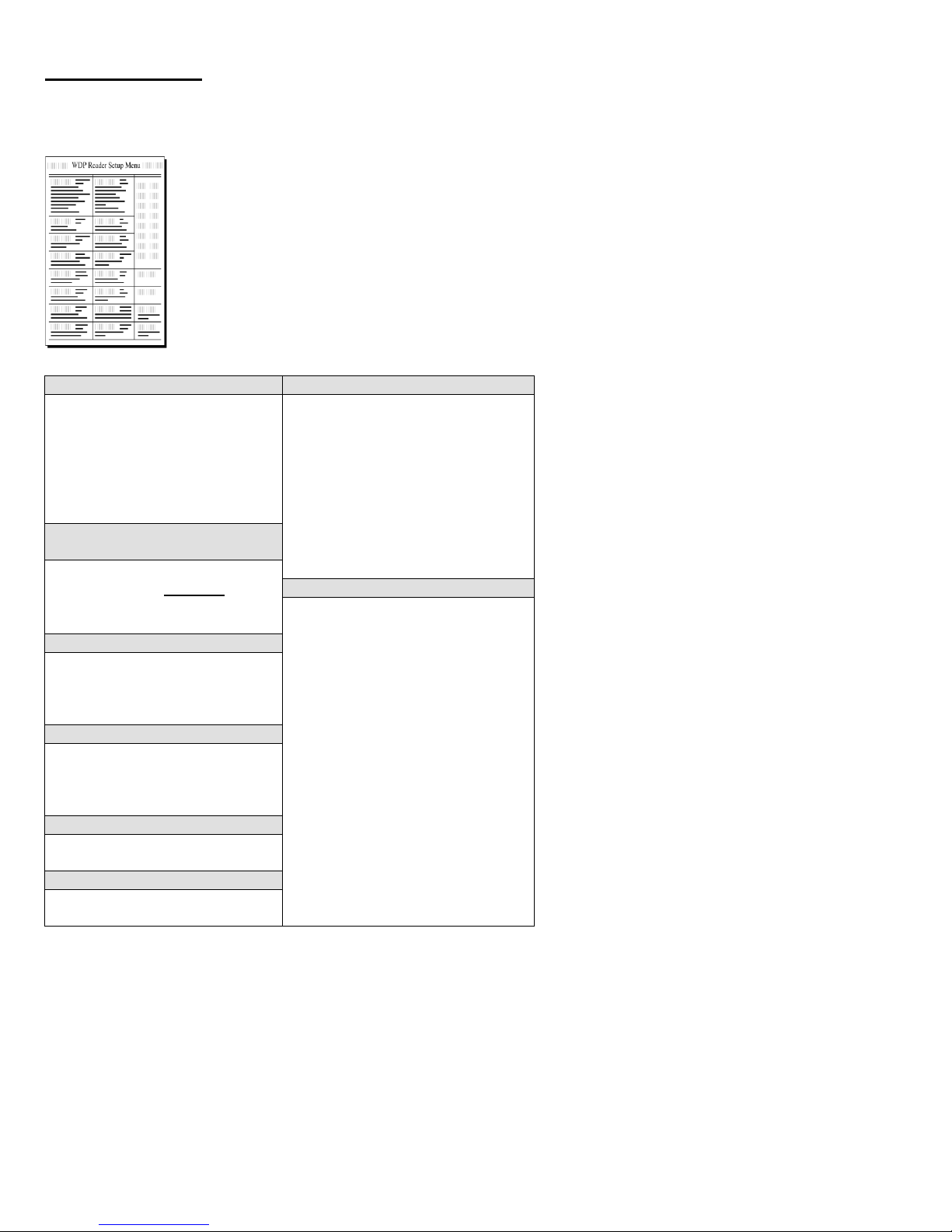
On the included CD-ROM you will find the RF Laser Setup Menu sheet. This simple
menu lets you easily configure the RF Laser Reader to work with almost any computer
system, and to tailor its bar code reading and data format characteristics.
Be sure to read the scanning instructions on the next page. To read Setup Menu bar codes
and configure your reader, you must know the right way to scan bar codes.
These are the RF Laser Reader's default settings and are shipped configured to these
settings; they can be reset to them at any time by scanning the Start Setup and Reset codes
on the RF Laser Setup Menu.
If you need to change any of the default settings, or would like to learn more about the Wireless scanner
options, the next several pages will explain, step by step, how to set them.
10
Page 11
Laser Scanning Instructions
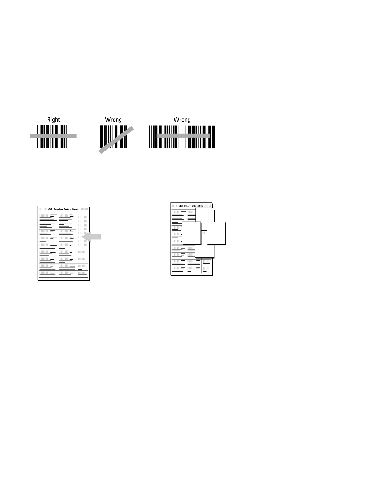
Using a laser scanner is basically as simple and intuitive as "point and shoot" at a distance of 0-24", depending
on the density of the bar code.
Basically, the laser scanner's beams must cross every bar and space on the bar code, without touching any
other bar codes, as shown in the first example below. You'll need to hold the scanner further away to produce
a wider beam for large bar codes, and closer for bar codes with bars very close together.
Even though momentary exposure to a laser's low-power, visible-light is not known to be harmful, you should
not aim the beam into anyone's eyes.
The important thing to remember about using a laser with the RF Laser Reader Setup Menu is that you need to
make sure the scanner's beam covers only one bar code at a time. The laser scanner's beam is wide enough,
and the configuration bar codes close together enough that you will need to use your fingers or a few pieces of
note paper to "block off" bar codes adjacent to whatever configuration bar code you need to read.
For example, to
read this "5" bar
code on the Setup
Menu, you would
need to cover any
adjacent bar codes
with paper or a
finger first, as shown.
11
Page 12

Using The 1D RF Laser Setup Menu
Note: If you are using the 2D 520-RF then refer to the 2D setup chart starting on page 24.
1. To configure your reader using the RF Laser Setup Menu, you must first scan the Start Setup code at the
top left corner. Do this now. You'll hear two beeps. During Setup, nothing will be transmitted to your
computer; the Reader Setup Menu codes are strictly for configuring the reader. If you did not hear two
beeps, try scanning the code again, until you hear the two beeps. If you've never scanned bar codes before,
read the scanning instructions on page 6 before continuing. The scanner LED will turn green when in
setup mode.
2. Next, choose the setting you want to change an option for and scan its code. You will hear 2 beeps each
time you read a setup barcode.
3. Then, choose the option you want to change, from the list next to the setting bar code you just scanned.
Using the "Barpad Table" on the right side of the Reader Setup Menu, scan the number or letter associated
with the option you have selected to change. Some settings (like Preamble and Postamble) require the
SET barcode to terminate a string entry but most are single character.
4. Now scan End Setup (at the top-right corner of the Reader Setup Menu to complete the setup. You'll hear
three beeps.
The next several pages will show you all of the various Wireless Reader options. Default settings are shown
in bold in this manual and marked with an * on the Reader Setup Menu.
12
Page 13

Enable Code 39
0
Disable Code 39
1
Enable Full ASCII Code 39
2
Disable Full ASCII Code 39
3
Enable Code 39 Accumulate Mode
4
Disable Code 39 Accumulate Mode
5
Enable Start/stop character transmission
6
Disable Start/Stop character transmission
7
Enable Mod 43 Check Digit
8
Disable Mod 43 Check Digit
9
Enable Check Digit Transmission
A
Disable Check Digit Transmission
B
Caps Lock ON
C
Caps Lock OFF
D
Note: If you are using the 2D 520-RF then refer to the 2D setup chart starting on page 24.
Code 3 of 9 (Code 39)
See page 20 for information about Accumulate Mode (this setting also controls Code 93 and Code 128).
Enabling Start/Stop character transmission means that the RF Laser Reader will transmit the * Start/Stop
characters to your computer along with the data. For example, data of 1234 would be transmitted as *1234*.
Enabling the Mod 43 Check Digit requires the units position of your data to match the calculation for the
check digit explained in Appendix C.
If you've enabled the check digit, enabling Check Digit transmission causes the reader to transmit it to your
computer along with the bar code data.
"Caps Lock ON" means that for all codes lower case letters read as data will be transmitted as upper case,
and upper case as lower. Numbers, punctuation & control characters are not affected. This applies to Code
128 and Code 93 also.
"Caps Lock OFF" means that letters will be transmitted exactly as read.
13
Page 14

Enable UPC/EAN
0
Disable UPC/EAN
1
Enable UPC/EAN Supplements
2
Disable UPC/EAN Supplements
3
Enable transmission of UPC-A NSC and EAN-13 1st 2
4
Disable transmission of UPC-A NSC and EAN-13 1st 1 digits
5
Enable transmission of UPC-A and EAN–13 Check Digit
6
Disable transmission of UPC-A and EAN-13 Check Digit
7
Enable transmission of UPC-E NSC and EAN-8 1st Digit
8
Disable transmission of UPC-E NSC and EAN-8 1st Digit
9
Enable transmission of UPC-E and EAN-8 Check Digit
A
Disable transmission of UPC-E and EAN-8 check Digit
B
UPC-E Compressed
C
UPC=E Expanded
D
EAN-8 observes 9 & A above
E
EAN-8 is forced to transmit 8 digits
F
Note: If you are using the 2D 520-RF then refer to the 2D setup chart starting on page 24.
UPC/EAN
Enabling supplements allows you to read 2 and 5-digit supplemental codes used with magazines and
paperbacks. This disallows right-to-left reading of UPC codes, to assure that the supplement doesn't get
skipped.
Use setting 2 to enable reading of the 2 and 5 digit UPC/EAN supplements commonly found on magazines
and paperback books. Use this setting to force left to right reading of UPC codes, assuring that the
supplement code is not missed. This This setting also allows for reading of the UCC/EAN 128 Extended
Coupon Code. The Extended Coupon Code consists of a UPC code with a NSC of 5 or and EAN code with a
country code of 99 along with a C0de 128 supplemental code to the right. This setting allows you to read the
Code 128 supplement with the UPC/EAN, providing the UPC has a NSC of 5 or the EAN code has a country
code of 99. Without the correct NSC or country code, the Code 128 portion will be ignored; UPC code with an
NSC of 5 or EAN codes with country code of 99 will not be read unless there is a readable Code 128
supplemental code read also.
UPC-E Compressed Format transmits UPC-E codes as is; Expanded Format adds zeros to make them the
same length as UPC-A.
UPC-E can be used in either normal UPC-E format (implicit NSC of 0) or UPC-E1 format (NSC of 1). UPC-
E1 is enabled by scanning 2 of 5 Code and 8 (9 disables UPC-E1). It is very easy to partially read EAN-13 as
UPC-E1, so don't enable UPC-E1 if reading EAN-13.
If you wish to transmit UPC-A data in EAN-13 format, (an added leading 0 for the USA's country code),
scan Terminator Character and F. Scanning E, the default, sets UPC back to no country code transmitted.
ISBN, International Standard Book Numbering, bar codes are EAN-13 codes with a 5 digit supplement. If the
first three digits are the "Bookland" country codes of 978 for books or 977 for periodicals, then you can enable
transmission of EAN-13 bar codes in the ISBN format. Suppose you scan an EAN-13 with 5-digit supplement
which is a bar code of 978055337062153495. It would be transmitted in ISBN format as 0553370626 (as of
Jan.1, 2006, the correct ISBN format is the EAN-13 bar code with the 5 digit supplement). 055337062 are the
first nine digits of the ISBN format, and 6 is the newly calculated Mod-11 check digit.
To enable the transmission of the ISBN format, scan Terminator Character and D. Scanning C, the
default, disables conversion to ISBN format back to regular EAN-13 format.
14
Page 15

Disable Code 128
0
Enable Code 128
1
Disable UCC/EAN-128
2
Enable UCC/EAN-128
3
Enable Storage Tek Tape Label Code
C
Disable Storage Tek Tape Label Code
D
Bar Code IDs transmitted
E
Bar Code IDs not transmitted
F
Codabar
a
I2of5
e
93 i Plessey
x
Code 39
b
2of5
f
UPC-E0
n
LabelCode4
y
UPC-A
c
128
g
UPC-E1
o
LabelCode5
z
EAN-13
d
MSI
j
EAN-8
p
STK
s
Disable MSI
0
Enable MSI with 1 Mod 10 check digit
1
Enable MSI with 2 Mod 10 check digits
2
Enable MSI with 1 Mod 11 and 1 Mod 10 check digit
3
Transmit No Check Digits
4
Transmit 1 Check digit
5
Transmit 2 Check digits
6
Enable Plessey (mutually exclusive with MSI)
7
Enable LabelCode5
8
Enable LabelCode4
9
Enable Codabar
0
Disable Codabar
1
Enable CLSI Codabar
2
Disable CLSI Codaber
3
Enable Start/Stop Character Transmission
4
Disable Start/Stop Character Transmission
5
Note: If you are using the 2D 520-RF then refer to the 2D setup chart starting on page 24.
Code 128
To enable a Bar Code ID character to be transmitted at the beginning of each bar code read, scan E. The
ID’s are as follows:
To disable bar code ID characters, scan F.
MSI and Plessey
Codabar
CLSI format is a form of Codabar often used by libraries.
Enabling Start/Stop character transmission means that the RF Laser will transmit start/stop characters to your
computer along with data. If you're varying start/stop characters with different label types, you'll want to enable
transmission.
15
Page 16

Enable Interleaved 2 of 5
0
Disable Interleaved 2 of 5
1
Enable Interleaved 2 of 5 Check Digit
2
Disable Interleaved 2 of 5 Check Digit
3
Enable Check Digit Transmission
4
Disable Check Digit Transmission
5
Enable Standard 2 of 5
6
Disable Standard 2 of 5
7
Enable Code 93
0
Disable Code 93
1
Enable Full ASCII Code 93
2
Disable Full ASCII Code 93
3
Note: If you are using the 2D 520-RF then refer to the 2D setup chart starting on page 24.
2 of 5 Code
Enabling the Check Digit requires the data’s unit’s position to match the calculation for the check digit. If
you've enabled the check digit, enabling Check Digit transmission causes the reader to transmit it to your
computer along with the bar code data.
2 of 5 Data Length
2 of 5 Code is so susceptible to interpreting partial scans as valid reads that the Radio/Freedom Reader
uses fixed-length data as a safeguard. To choose a data length, scan it as a two-digit number using the Barpad
Table. For example, to select 8-digit data length, you would scan a 0 and then an 8. Because Interleaved 2
of 5 is required to be an even number of digits in length, you must use an even number. If you're unsure of
your bar code length, temporarily set the length to 00, read a bar code, and count its digits and then set it to
the actual length. DO NOT PERMANENTLY SET THE 2 of 5 LENGTH TO 00 or you will get
misreads!
Code 93
16
Page 17

Enter (carriage return)
0
None
1
HT 2 CR/LF
3
Bar Code Data
Preamble
Data Transmitted
123
XYZ
XYZ123
12345678
~3XYZ
XYZ45678
12345678
~9
12345678
12345
~A
12345
123456
~5
6
Note: If you are using the 2D 520-RF then refer to the 2D setup chart starting on page 24.
Terminator characters
Depending on your application, you may wish your Wireless Reader to transmit bar code data to your
computer with an Enter (carriage return), a Tab at the end, or with no extra terminating character at all.
If you need a terminator character other than CR or HT or CR/LF, you can get it by specifying None here and
then selecting your desired terminator character(s) specified in the Postamble.
Preamble
A "Preamble" is a user-specified data string transmitted at the beginning of each bar code. For example, if you specify
the preamble @@ and read data of 123456, "@@123456" would be transmitted to your computer. The Preamble
applies to the scanner, not the base station because there may be multiple scanners per base.
The default is no preamble. To select a preamble, scan up to 15 characters from the "FULL ASCII MENU" on the back of
the Reader Setup Menu, and then scan SET when you're done. To return to the no preamble setting, scan Clear here
instead of scanning SET or any characters from the FULL ASCII MENU.
You can trim 1-15 leading characters from bar code codes by scanning a ~ (tilde -- ASCII 126) followed by a single
digit, 1 through F, as part of the Preamble. (Bar codes that are shorter than the amount-to-trim are transmitted with no
trimming.) Consider the examples in the following table to understand how trimming works:
You can also trim selectively by bar code type. For example, you can trim 2 characters from Code 39 and a different amount
from other bar code outputs. This is done by using the bar code ID character in conjunction with the tilde (~). A preamble of
~b2~c1 says trim 2 characters from the front of Code 39 output and trim 1 character from the front of UPC-A. Refer to the
Code 128 parameter on page 13 for a list of the ID character associated with each bar code type.
A final use of the Preamble/Postamble is to enter a minimum/maximum length check for bar code data read. Use the
Preamble or Postamble by entering |nnmm where "|" is ASCII 124, "nn" is the two digit minimum to be read and "mm"
is the two digit maximum to be read.
17
Page 18

Bar Code Data
Postamble
Data Transmitted
123
XYZ
123XYZ
12345678
~3XYZ
12345XYZ
12345678
~9
12345678
12345
~A
12345
123456
~5
1
Note: If you are using the 2D 520-RF then refer to the 2D setup chart starting on page 24.
Postamble
"Postamble" refers to a user-specified data string transmitted at the end of each bar code. For instance, if you
specify the postamble @@ and read data of 123456, "123456@@" would be transmitted to your computer.
The default is no postamble. To select a postamble, scan up to 15 characters from the "FULL ASCII MENU"
on the back of the Reader Setup Menu, and then scan SET when you're done. To return to the no postamble
setting, scan CLEAR here instead of scanning SET or any characters from the FULL ASCII MENU.
You can trim 1-15 trailing characters from bar code codes by scanning a ~ (tilde -- ASCII 126) followed by a
single hex digit, 1 through F. (Bar codes which are shorter than the amount-to-trim are transmitted without
trimming.) Consider the examples in the following table to understand the options of the Postamble:
Bar codes that are shorter than the sum of the Postamble trimming and Preamble trimming will be transmitted without
trimming. Selective trimming and min/max bar code data is also supported through Postamble specifications, (See
Preamble above for complete details).
Characters
This setup option allows you to output ASCII characters different from the ones scanned.
For example: Suppose you want to output a hex 92 character every time you scan a 1 (hex 31); you want to
remap hex 31 to hex 92, (If you're using 8 data bits, output of 80-F8 codes is possible.)
1) Scan the Start Setup Bar Code
2) Scan the Characters Bar Code on the Setup Sheet.
3) Scan 3 1 and 9 2 to output hex 92 when reading a "1".
4) Scan up to 7 other pairs of character reassignments.
5) Scan Set when complete.
6) Scan End Setup to exit setup mode.
Hex values for each character code are shown on the Full ASCII Menu. The equivalent decimal values are
also shown for each character.
You can also eliminate characters by reassigning hex codes to FF. For example, to strip all $ (dollar sign)
characters from transmission, you would follow the above instructions and scan 2 4 F F in step 3.
Reset
Once you are in the Setup Mode, don't scan Reset unless you're sure you want to restore the RF Laser to its
default settings (as described on page 5), erasing all changes you've made.
18
Page 19

DIFFICULT CODE SETUP OPTIONS (does not apply to 2D RF Laser)
Aiming Laser Dot: (LZ404-RF only) Sometimes it is difficult to see the laser beam and know you are on the bar code,
especially if you are attempting to read outdoors in direct sunlight. The laser can be output as a bright dot for a few
seconds, allowing the user to place the dot in the middle of the bar code; then the laser beam starts sweeping for the
read. As shipped, the laser beam never forms an aiming dot, but you can program a number of seconds that you wish the
aiming dot to appear before the beam scans using the following setting:
Scan Start Setup
Scan Aiming Dot Duration
Scan 1 to select a 1 second aiming dot, or
2 to select a 2 second aiming dot, or
3 to select a 3 second aiming dot, or
4 to select a 4 second aiming dot, or
5 to select a 5 second aiming dot, or
0, the default, to eliminate an aiming dot.
Scan End Setup
4-second beam: Another option with problem reading conditions is to increase the length of the time the scanner
attempts to read, from the default 2-second beam to a 4-second beam. To select the 4-second beam:
Scan Start Setup
Scan 4-Second Beam
Scan 1 to select the 4-second beam
Scan End Setup
To return to the default 2-second beam, scan 0 instead of 1.
Automobile VIN READING:
There is special support for reading automobile Vehicle Identification Numbers, VIN, remotely from the computer. (CCDs
will not read through a windshield, only laser scanners.) You may want to use the aiming dot above too.
"Difficult Code 39 Reading": This feature facilitates reading of the VIN number on automobiles, which is often a
difficult-to-read bar code, especially reading through a windshield. VIN numbers are long, often weathered, often dirty,
and challenging to read.
To enable the more aggressive Code 39 algorithms necessary to read windshield VINs:
Scan Start Setup
Scan Difficult Code 39 Reading
Scan 1 for windshield reading
Scan End Setup
To return to the default Code 39 decode algorithms, scan 0 instead of 1.
"Double-scan checking": When reading a VIN, you will also want to disable double scan checking. The reader’s
default is to not output or beep until it has two successive identical decodes. This is an acceptable safeguard with most
codes, but with VIN numbers read through a windshield, you will have to deactivate double scan checking to get timely
reads.
Scan Start Setup
Scan Double Decode
Scan 0 to disable double decode
Scan End Setup
To enable double scan checking, scan 1 instead of 0.
19
Page 20
7
8
9
4
5
6
1
2
3
0
Clear Buffer
Enter
Accumulate Mode (1D only)
Accumulate Mode is an option (which can be enabled or disabled using the Reader Setup Menu's Code 39
section) allowing the reader to accumulate multiple bar codes in its buffer, then transmit them to the computer
as if they had been a single bar code. This is useful for entering quantities and other variable data.
It works with Code 39 only, and can't be used with a check digit. When the reader reads a bar code with a
leading space, it beeps and buffers the data without transmission. It continues to read and buffer bar codes (up
to 40 characters) until it reads a bar code without a leading space. Then the entire buffer (including that last
code) is transmitted as one long bar code. A bar code of a double minus (--) sign clears the buffer. Scanning a
backspace code ($H) backspaces in Full ASCII mode. A handy code for Enter (as seen on the "Barpad"
below) is a Start/Stop only. (No data.) The code to use for testing the transmission link between the RF Laser
Scanner and the RF Base Station is the CLEAR BUFFER code (the same bar code as titled Link Test on the
Setup Menu. It will cause beeps to be heard, but no data will be transmitted to the computer -- testing blind
with no computer consequence.
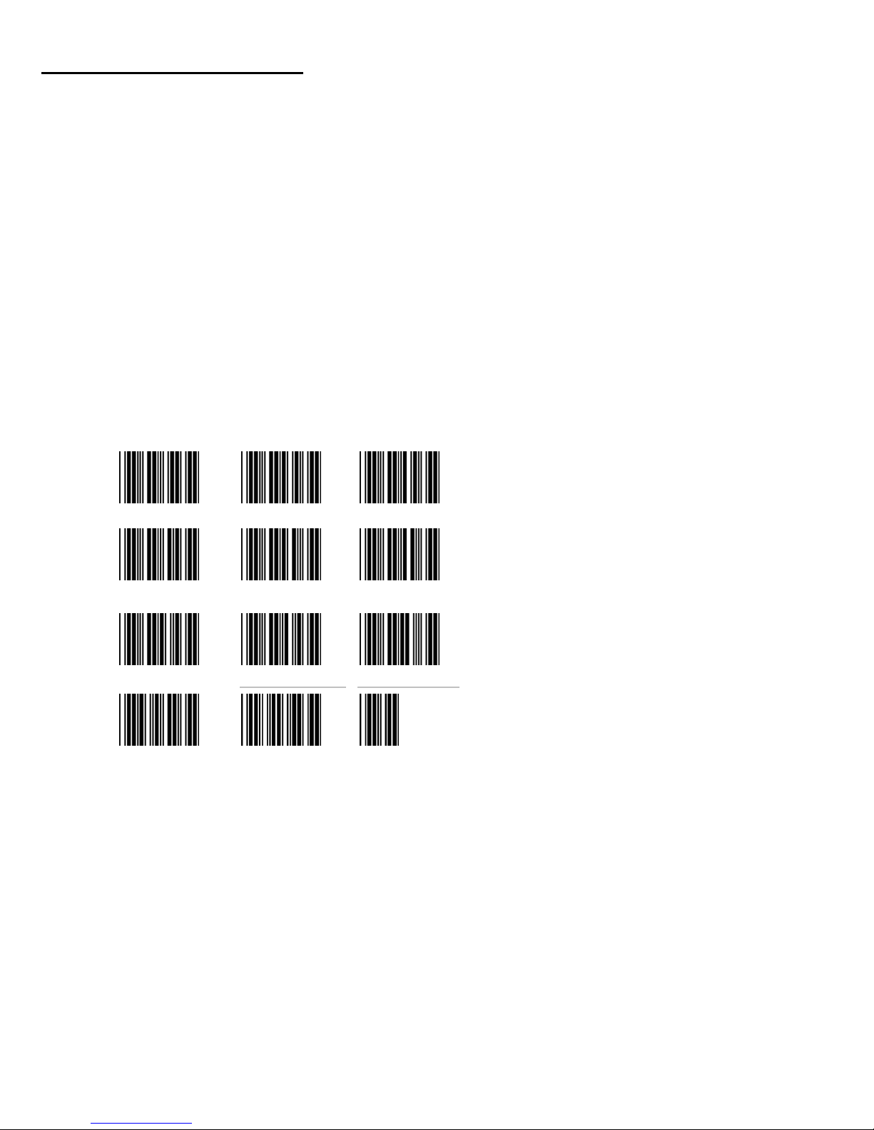
This numeric "Barpad" illustrates Accumulate Mode. Scan 5, 3, 8, and Enter. The reader transmits a single
message of 538.
20
Page 21

PC Key
Full ASCII Menu Bar Code
F1
SOH (f1)
F2
STX (f2)
F3
ETX (f3)
F4
EOT (f4)
F5
ENQ (f5)
F6
ACK (f6)
F7
BEL (f7)
F8
SO (f8)
Numpad 5*
Null 5
Enter
CR
F9
SI (f9)
F10
DLE (f10)
Del
Null .
Insert
Null 0
Left Arrow*
Null 4
Rt Arrow*
Null 6
Dn Arrow*
Null 2
Up Arrow*
Null 8
Pg Up*
Null 9
Pg Dn*
Null 3
Home*
Null 7
End*
Null 1
Shift ON
EM (Shift ON)
Shift OFF
SUB (Shift OFF)
Control On
FS (Ctrl ON)
Control Off
GS (Ctrl OFF)
Alt On
RS (Alt ON)
Alt Off
US (Alt OFF)
Function/Control Key Support
The RF Laser can also transmit key sequences for function, control, alt (command and option keys on Macs),
cursor and shift keys, for ease of use with the many software packages using these keys for menus or
commands. You can include these codes in other bar codes, or you can scan these “keystrokes” into your
Preamble or Postamble in order to add them to every scan from your reader. You must have Full ASCII Code
39 enabled on your reader (this is the default setting). Scan the corresponding bar code (or pairs of codes for
Pg Up, Pg Dn, Home, etc) from the Full ASCII menu to emulate the chosen key.
* refers to the keys on the Number pad on the far right side of a PC keyboard. To emulate any of the keys
above, scan the appropriate bar code from the FULL ASCII MENU. For example, to emulate the f5 key, scan
the ENQ bar code.
Simply scan the correct bar code(s) from the FULL ASCII MENU. For example, if the WDP reads the bar
code SOH (ASCII 001 -- a control-A) from the FULL ASCII MENU, it will transmit an F1 key.
Shift, Ctrl and Alt keys require three sequences:
1) The ON code generated when the Shift, Ctrl or Alt key is pressed.
2) The other key to be used in conjunction with the Shift, Ctrl or Alt key.
3) OFF code generated when the Shift, Ctrl or Alt key is released.
(For example, to create a Control C bar code: use Control ON, C, and Control OFF. To put Control C in a
Preamble or Postamble, scan from the Full ASCII Menu: Control ON, C, and Control OFF).
Function keys F11 and F12
Function keys F11 and F12 require two bar codes to be scanned to make these functions keys. The F11 key is
created by combining the Null and SOH. The F12 key is created by combining the Null and the STX.
21
Page 22

Keystroke
Full ASCII Menu
Bar Code
Alt ON
RS
Ins (0 on the numeric pad)
DC2
Down Arrow (2 on the numeric
pad)
NAK
Numpad 5
LF
Ins (0 on the numeric pad
DC2
Alt OFF
US
Windows Key
The Windows key on a Windows keyboard is transmitted by scanning 4 bar codes - NULL and C for
Windows On (pressing down) and NULL and D for Windows Off (releasing the key).
Command and Option Keys on Mac USB Keyboards
When you have a WDP Reader attached to a Macintosh Computer's USB port, to emulate the Command key,
use the Windows key ON/OFF bar codes NULL, C (Command ON) and NULL, D (Command OFF) For the
Option Key ON/OFF use RS (Option On) and US (Option Off).
Transmitting any ASCII character using its 3-digit ASCII code
You can also transmit any ASCII character from 000 to 255 by emulating the PC technique of typing a
character's ASCII number on the numeric pad while holding down the Alt key. For example, to transmit
ASCII 250, you would scan the bar codes for:
22
Page 23

Troubleshooting
All Models Troubleshooting
The beam won’t stay on, or I just get a narrow beam when I pull the trigger, or the scanner won’t turn on
when I pull the trigger or the red LED flashes when I pull the trigger.
All of the above problems are an indication that your BATTERY IS TOO LOW. With any of the above
symptoms, recharge the battery in the RF Laser before assuming you have some other kind of problem.
The reader won't beep when reading bar codes
Recheck all the connections. Get close to the Base Station. Try reading the Link Test bar code, following
the steps for scanning on page 6.
If you hear two beeps, but see nothing on the screen, try scanning End Setup.
Reread the configuration section and make sure you properly enabled the bar code types you're trying to
read.
Extra characters at the beginning or end of your bar code data
Clear the Preamble and Postamble.
Poor read rate
Get close to the Base Station and try reading the test label (following the scanning instructions on page
6) as an example of a known good bar code. Examine your bar codes to make sure they have dark bars,
clearly defined bars and white spaces, and a "quiet zone" of at least 1/4 inch to the left and right. If the
bars are gray, or so dark that they "bleed" into the white spaces, the person or organization printing them
will need to adjust the printer or get a new ribbon or toner cartridge for it.
I get six beeps when the RF Laser powers up.
The unit needs repair. Call for an RMA.
The Orange light stays on the RF Laser Scanner
You are in Setup Mode. Scan End Setup on the Wireless Setup Menu.
You need more range
If you need more range consider using a USB Dock to allow the USB Base Station receiver to be
positioned with better line-of –sight to the RF Laser.
23
Page 24

USB Trouble Shooting
The Base Station's light flashes in Red cycles when the USB cable is connected.
The Base Station cannot enumerate. The driver is probably not installed correctly.
Occasionally the user will be unaware that he aborted his driver installation. Once the process has
started, it should finish successfully. If it doesn’t, you will not see any data on the screen when
scanning.
To resolve a driver installation problem follow the applicable instructions below:
Windows XP:
1. Go to the Start menu.
2. Select Control Panel.
3. Switch to "Classic View" if in "Category View"
4. Select "System".
5. Select "Hardware" tab.
6. Select "Device Manager"
7. Double Click on the" Human Interface Devices"
8. Locate the USB Human Interface Device with a "!" in the icon.
9. Click on Update Driver
10. Follow instructions. If XP fails to find the driver on the computer's hard disk, you may have to
insert and point to the original Windows XP CD to complete the installation.
11. Click "Finish"
Win98/ME:
1. Go to the "Start" menu.
2. Go to "Settings".
3. Select "Control Panel".
4. Go to "System".
5. Click on the "Device Manager" tab.
6. Double Click on the "USB Human Interface Devices" (it may be titled TriCoder HID Keyboard
instead).
7. Now click on the "Reinstall Driver" button.
8. Follow directions. If the installer cannot find the right driver file on your hard disk, you may have
to insert the original Windows 98 CD and point to it to complete the installation.
9. Click "Finish".
Win2000:
1. Log on as Administrator and open the “Administrative Tools” folder in your Control Panel.
2. Run the “Computer Management” utility.
3. Select the “Tree” tab on the left panel
4. Find the “Device Manager” entry under “System Tools” and click on it. The right panel will display
current devices.
5. Problem devices will be identified with an “!” icon. Find either the “HID Keyboard Device” under
Keyboards or the “USB Human Interface Device” under Human Interface Devices and double-click
on one of those entries.
6. Now select the “Driver” tab at the top of the window and click on the “Update Driver” button.
Follow the prompts to re-install the HID driver.
24
Page 25

Code Type
Enabled by Default
Additional Setup Info
UPC
yes
page 25
EAN
yes
page 26
EAN-13
yes
page 26
EAN-8
yes
page 26
Code 39
yes
page 28
Codabar
yes
page 29
Code 128
yes
page 31
Code 93
yes
page 32
Code 11
no
page 33
Industrial 2 of 5
yes
page 34
Interleaved 2 of 5
yes
page 34
S-Code
yes
page 34
Matrix 2 of 5
no
page 34
Chinese Post Matrix 2 of 5
no
page 34
MSI/Plessey
yes
page 35
UK/Plessey
yes
page 36
POSTNET
no
page 37
Intelligent Mail Bar Code
no
page 38
GS1 DataBar
yes
page 39
Korean Postal Authority
no
page 40
IATA
yes
page 41
Tri-Optic
yes
page 42
Telepen
yes
page 43
JPN (Customer Bar Code)
no
page 44
Worth Data 520-RF Bar Code Scanner Setup Guide
1D Codes:
25
Page 26
Code Type
Enabled by Default
Additional Setup Info
PDF417
yes
page 45
Micro PDF417
yes
page 46
Maxi Code
yes
page 47
QR Code
yes
page 48
Micro QR
yes
page 49
Aztec Code
yes
page 50
Aztec Runes
no
page 51
Data Matrix (ECC 200)
yes
page 52
Data Matrix (ECC 000-140)
no
page 52
Codablock F
no
page 53
Chinese Sensible Code
no
page 54
All Codes
no
page 55
Item
Setup Info
Number of Characters
page 56
Composite Codes
page 57
String Options (preamble, postamble)
page 58
String Options (prefix, suffix)
page 59
String Options (code identification)
page 62
Collective Reading
page 64
Read Mode
page 66
Imager Settings
page 70
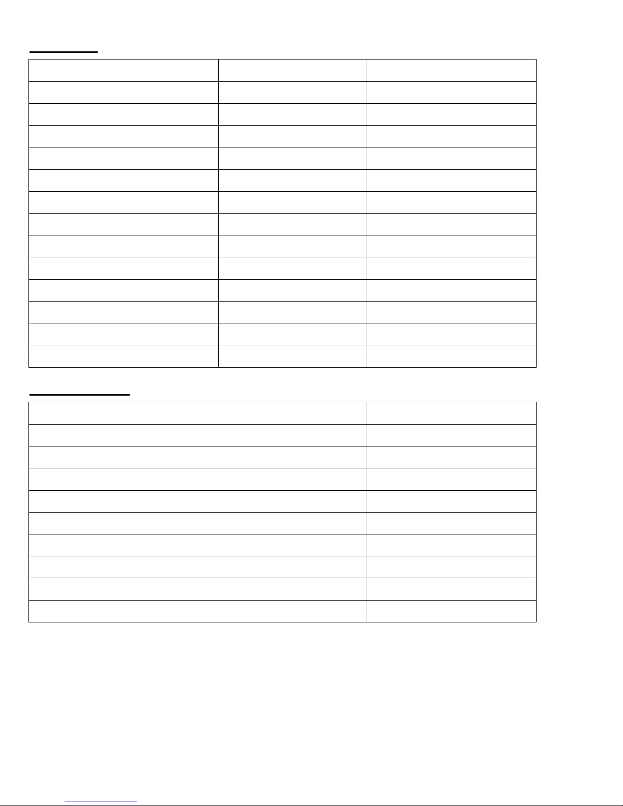
2D codes:
Other Options:
Warning: These setup codes are for the LZ520-2DRF only. Do not use these codes to setup the 2D
scanner on a 2D integrated Terminal or TriCoder. Use the internal menu to configure those units.
Note: Use caution when reading setup codes such that unwanted codes are not read.
26
Page 27
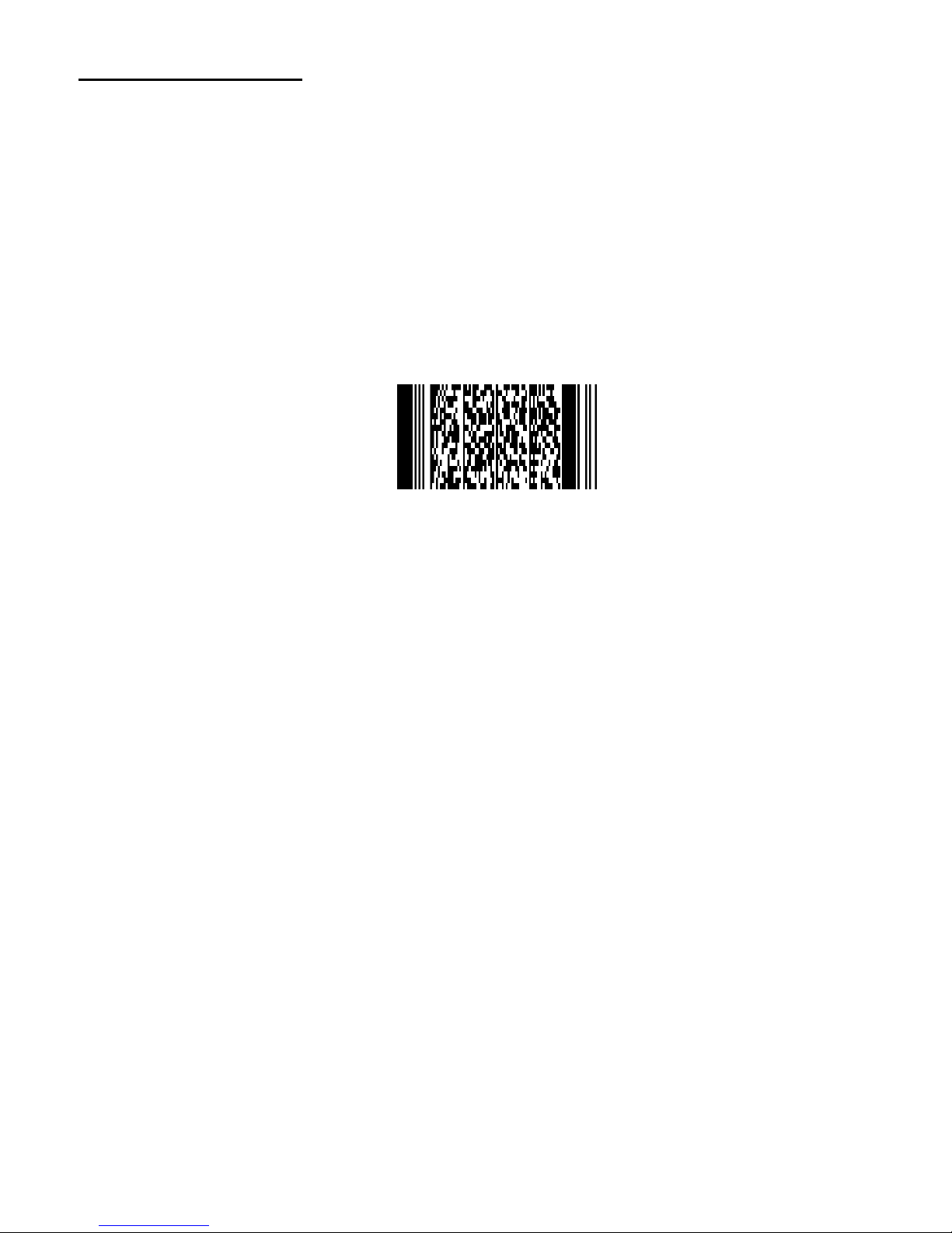
Set to factory default:
To set the scanner to factory defaults, scan the code below.
Reset All 2D Settings to Default
27
Page 28
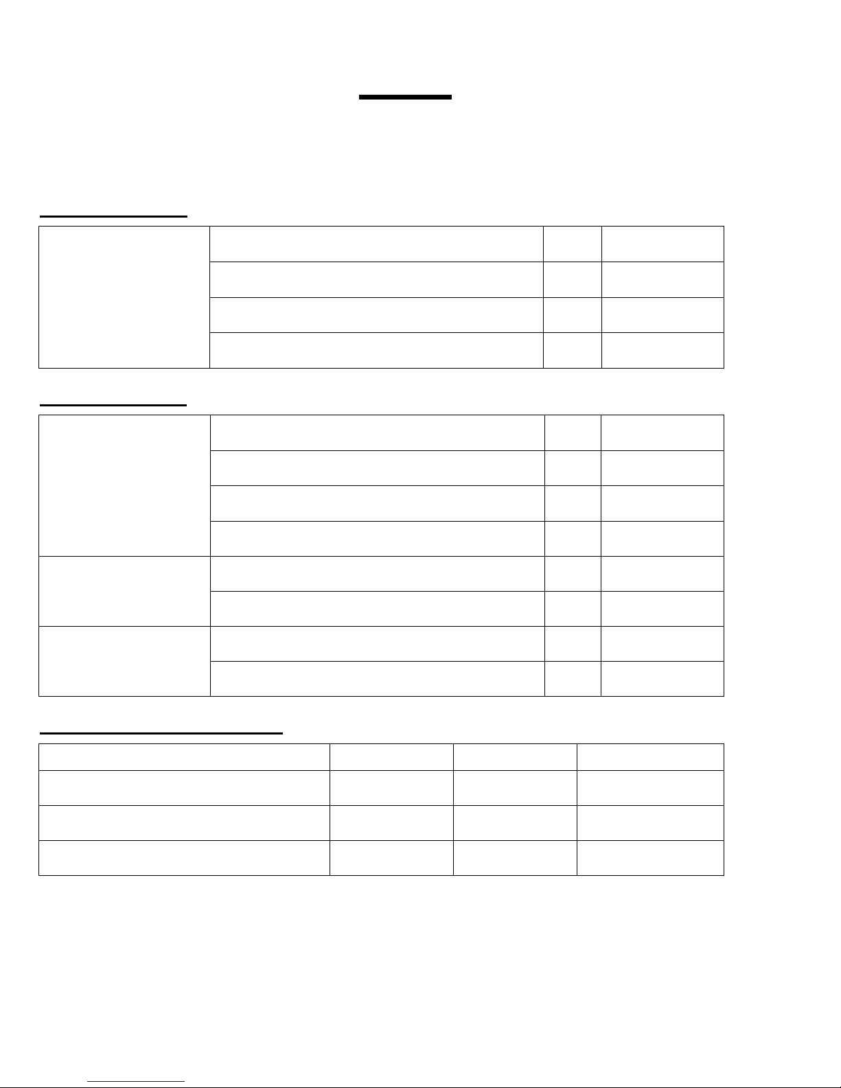
UPC-A
leading zero
check digit transmission
UPC-A, no leading zero, transmit check digit
default
,E3,
UPC-A, no leading zero, not transmit check digit
,E5,
UPC-A, leading zero, transmit check digit
,E2,
UPC-A, leading zero, not transmit check digit
,E4,
UPC-E
leading zero
check digit transmission
UPC-E, no leading zero, transmit check digit
default
,E7,
UPC-E, no leading zero, not transmit check digit
,E9,
UPC-E, leading zero, transmit check digit
,E6,
UPC-E, leading zero, not transmit check digit
,E8,
UPC-A,E conversion
transmit UPC-E
default
,6Q,
transmit as UPC-A
,6P,
UPC-E1 conversion
disable UPC-E1
default
,KP,
enable UPC-E1
,KQ,
UPC Symbologies
Exclusive
Enable
Disable
UPC without supplement (default enable)
,J1,
,R1,
,X4B,
UPC with 2-digit supplement
,J2,
,R2,
,X4C,
UPC with 5-digit supplement
,J3,
,R3,
,X4D,
UPC
Start Setup End Setup
,ZZ, ,ZZ,
UPC-A Settings:
UPC-E Settings:
UPC Supplement Settings:
note: setting any symbology to exclusive will disable all other symbologies
28
Page 29
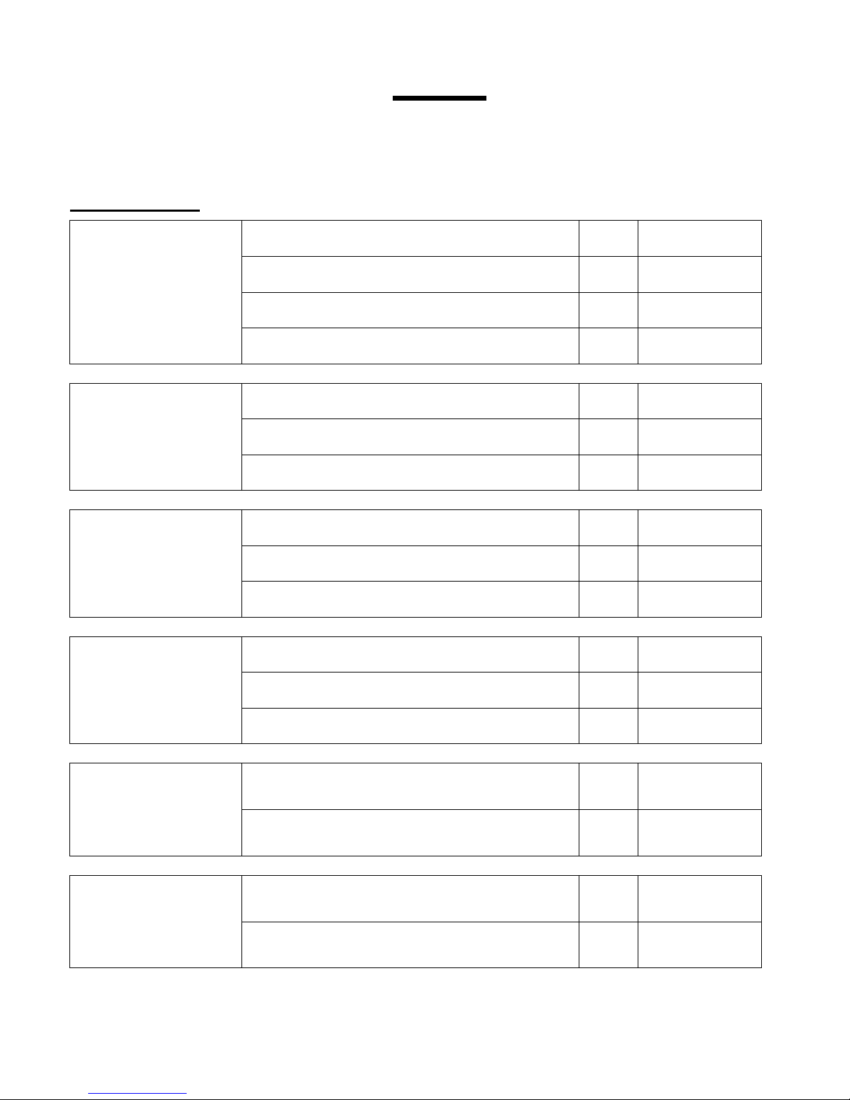
EAN-13 and EAN-8
Check Digit
Transmission
not transmit EAN-13 check digit
,6J,
transmit EAN-13 check digit
default
,6K,
not transmit EAN-8 check digit
,6H,
transmit EAN-8 check digit
default
,6I,
EAN-13 and EAN-8
ISBN Conversion
disable ISBN conversion
default
,IB,
enable ISBN conversion
,IA,
enable ISBN if possible
,IK,
EAN-13 and EAN-8
ISSN Conversion
disable ISSN conversion
default
,HN,
enable ISSN conversion
,HO,
enable ISSN if possible
,4V,
EAN-13 and EAN-8
ISMN Conversion
disable ISMN conversion
default
,IO,
enable ISMN conversion
,IP,
enable ISMN if possible
,IQ,
EAN-13
Forced Add-On 1
enable EAN forced add-on when EAN13 starts
with 378 / 379 / 529
,-G,
disable EAN forced add-on when EAN13 starts
with 378 / 379 / 529
default
,-H,
EAN-13
Forced Add-On 2
enable EAN forced add-on when EAN13 starts
with 434 / 439 / 414 / 419 / 977 / 978
,-C,
disable EAN forced add-on when EAN13 starts
with 434 / 439 / 414 / 419 / 977 / 978
default
,-D,
EAN
Start Setup End Setup
,ZZ, ,ZZ,
EAN Settings:
29
Page 30
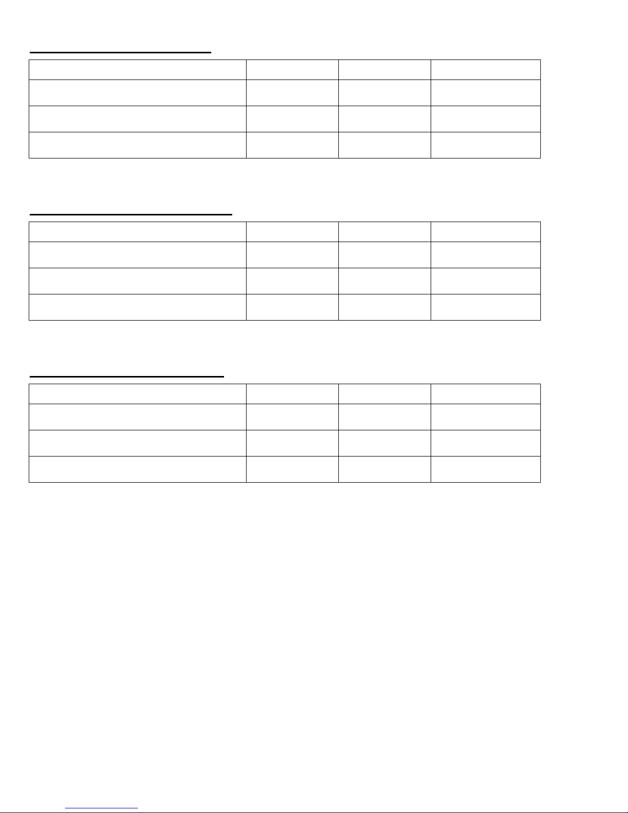
EAN Symbologies
Exclusive
Enable
Disable
EAN no supplement (default enable)
,J4,
,R4,
,X4E,
EAN with 2-digit supplement
,J5,
,R5,
,X4F,
EAN with 5-digit supplement
,J6,
,R6,
,X4G,
EAN Symbologies
Exclusive
Enable
Disable
EAN-13 no supplement (default enable)
,JG,
,JU,
N/A
EAN-13 with 2-digit supplement
,JH,
,JV,
N/A
EAN-13 with 5-digit supplement
,JI,
,JW,
N/A
EAN Symbologies
Exclusive
Enable
Disable
EAN-8 no supplement (default enable)
,JA,
,JO,
N/A
EAN-8 with 2-digit supplement
,JB,
,JP,
N/A
EAN-8 with 5-digit supplement
,JC,
,JQ,
N/A
EAN Supplement Settings:
note: setting any symbology to exclusive will disable all other symbologies
EAN-13 Supplement Settings:
note: setting any symbology to exclusive will disable all other symbologies
EAN-8 Supplement Settings:
note: setting any symbology to exclusive will disable all other symbologies
30
Page 31
Code 39
Exclusive
Enable
Disable
Code 39 Enable/Disable (default enable)
,A2,
,B2,
,VB,
Full ASCII Conversion
normal code 39
default
,D5,
full ASCII code 39
,D4,
full ASCII code 39 if possible
,+K,
Code 39 and
It Pharmaceutical
Check Digit (CD)
not check CD
default
,C1,
check CD
,C0,
not transmit CD
,D8,
transmit CD
default
,D9,
Code 39 and
It Pharmaceutical
Misc Settings
not transmit start/stop
default
,D1,
transmit start/stop
,D0,
minimum data = three characters
,8D,
minimum data = one character
default
,8E,
disable concatenation
default
,+M,
enable concatenation
,+L,
Italian Pharmaceutical Options
Enable
Disable
Italian Pharmaceutical Only (default disable)
,D6,
,D5,
Italian Pharmaceutical if Possible (default disable)
,D7,
,D5,
Leading A Transmission (default disable)
,DB,
,DA,
Code 39
Start Setup End Setup
,ZZ, ,ZZ,
Code 39 Settings:
note: setting any symbology to exclusive will disable all other symbologies
31
Page 32
Codabar
Exclusive
Enable
Disable
Codabar Enable/Disable (default enable)
,A3,
,B3,
,VC,
Codabar
ABC, CX Conversion
enable only Codabar normal mode
default
,HA,
enable only ABC code
,H4,
enable only CX code
,H5,
enable Codabar / ABC and CX
,H3,
Codabar
Check Digit (CD)
not check CD
default
,H7,
check CD
,H6,
not transmit CD
,H9,
transmit CD
default
,H8,
Codabar
Start / Stop
not transmit start / stop
default
,F0,
start / stop = ABCD / ABCD
,F3,
start / stop = abcd / abcd
,F4,
start / stop = ABCD / TN*E
,F1,
start / stop = abcd / tn*e
,F2,
start = <DC1><DC2><DC3><DC4>
stop = <DC1><DC2><DC3><DC4>
,HJ,
Codabar
Start Setup End Setup
,ZZ, ,ZZ,
Codabar Settings:
note: setting any symbology to exclusive will disable all other symbologies
32
Page 33
Codabar
Minimum Digit
minimum data = one character
,HC,
minimum data = three characters
,HB,
minimum data = five characters
default
,HF,
Codabar
Space Insertion
disable space insertion
default
,HE,
enable space insertion
,HD,
Codabar
Inter-Character
Gap Check
disable inter-character gap check
,HI,
enable inter-character gap check
default
,HH,
Codabar Settings Continued:
33
Page 34
Codabar
Exclusive
Enable
Disable
Code 128 Enable/Disable (default enable)
,A6,
,B6,
,VE,
Code 128 and
GS1-128 (EAN-128)
EAN-128 Conversion
disable GS1-128
default
,OF,
enable GS1-128 only
,JF,
enable EAN-128 if possible
,OG,
Code 128 and
GS1-128 (EAN-128)
Concatenation
disable concatenation (FNC2 message append)
default
,MP,
enable concatenation (FNC2 message append)
,MO,
Code 128
Start Setup End Setup
,ZZ, ,ZZ,
Code 128 Settings:
note: setting any symbology to exclusive will disable all other symbologies
34
Page 35
Symbology
Exclusive
Enable
Disable
Code 93 (default enable)
,A5,
,B5,
,VD,
Code 93
Check Digit (CD)
not transmit CD
default
,DZ,
transmit CD
,DY,
Code 93
Start Setup End Setup
,ZZ, ,ZZ,
Code 93 Settings:
note: setting any symbology to exclusive will disable all other symbologies
35
Page 36
Symbology
Exclusive
Enable
Disable
Code 11 (default disable)
,BLB,
,BLC,
,BLA,
Code 11
Check Digit (CD)
not check CD
,BLF,
check 1 CD
,BLG,
check 2 CD
,BLH,
check auto 1 or 2 CD
default
,BLI,
not transmit CD
default
,BLJ,
transmit CD
,BLK,
Code 11
Start Setup End Setup
,ZZ, ,ZZ,
Code 11 Settings:
note: setting any symbology to exclusive will disable all other symbologies
36
Page 37
Symbology
Exclusive
Enable
Disable
Industrial 2 of 5 (default enable)
,J7,
,R7,
,X4K,
Interleaved 2 of 5 (default enable)
,J8,
,R8,
,X4L,
S-Code (default enable)
,RA,
,R9,
N/A
Matrix 2 of 5 (default disable)
,AB,
,BB,
N/A
Chinese Post Matrix 2 of 5
(default disable)
,JE,
,JS,
,JT,
2 of 5 and S-Code
Check Digit (CD)
not check CD
default
,G0,
check CD
,G1,
not transmit CD
,E1,
transmit CD
default
,E0,
2 of 5 and S-Code
Space Check
disable space check for Industrial 2 of 5
,GK,
enable space check for Industrial 2 of 5
default
,GJ,
S-Code Conversion
not transmit S-Code as Interleaved 2 of 5
default
,GH,
transmit S-Code as Interleaved 2 of 5
,GG,
2 of 5 and S-Code
Minimum Digit
minimum data = one character
minimum data = three characters
,GF,
minimum data = five characters
default
,GI,
2 of 5 and S-Code
Start Setup End Setup
,ZZ, ,ZZ,
2 of 5 and S-Code Settings:
note: setting any symbology to exclusive will disable all other symbologies
37
Page 38
Symbology
Exclusive
Enable
Disable
MSI / Plessey (default enable)
,A7,
,B7,
,VF,
MSI / Plessey
Check Digit (CD)
not check CD
,4A,
check 1 CD = mod 10
default
,4B,
check 2 CD = mod 10/mod 10
,4C,
check 2 CD = mod 10/mod 11
,4D,
check 2 CD = mod 11/mod 10
,4R,
check 2 CD = mod 11/mod 11
,4S,
MSI / Plessey
Check Digit (CD)
Transmission
not transmit CD
,4G,
transmit CD 1
default
,4E,
transmit CD 1 and CD 2
,4F,
MSI / Plessey
Start Setup End Setup
,ZZ, ,ZZ,
MSI / Plessey Settings:
note: setting any symbology to exclusive will disable all other symbologies
38
Page 39
Symbology
Exclusive
Enable
Disable
UK / Plessey (default enable)
,A1,
,B1,
,VA,
UK / Plessey
Check Digit (CD)
not transmit CD
,4O,
transmit CD
default
,4N,
UK / Plessey
Space Insertion
disable space insertion
default
,DO,
enable space insertion
,DN,
UK / Plessey
X Conversion
disable A -> X conversion
default
,DP,
enable A -> X conversion
,DQ,
UK / Plessey
Start Setup End Setup
,ZZ, ,ZZ,
UK / Plessey Settings:
note: setting any symbology to exclusive will disable all other symbologies
39
Page 40
Symbology
Exclusive
Enable
Disable
POSTNET (default disable)
,D6C,
,D6A,
,D6B,
POSTNET
Start Setup End Setup
,ZZ, ,ZZ,
POSTNET Settings:
note: setting any symbology to exclusive will disable all other symbologies
40
Page 41
Symbology
Exclusive
Enable
Disable
IMBC (default disable)
,D5H,
,D5F,
,D5G,
Intelligent Mail Bar Code
Start Setup End Setup
,ZZ, ,ZZ,
Intelligent Mail Bar Code Settings:
note: setting any symbology to exclusive will disable all other symbologies
41
Page 42
Symbology
Exclusive
Enable
Disable
GS1 DataBar
Omnidirectional
Truncated
Stacked
Stacked Omnidirectional
(default enable)
,J9,
,JX,
,SJ,
GS1 DataBar Limited
(default enable)
,JJ,
,JY,
,SK,
GS1 DataBar
Expanded
Expanded Stacked
(default enable)
,JK,
,DR,
,SL,
GS1 DataBar
All Above Types
(default enable)
,BC6,
,BCI,
,BCU,
GS1 DataBar
Check Digit (CD)
not transmit CD
,DM,
transmit CD
default
,DL,
GS1 DataBar
AI Transmission
not transmit application identifier
,DT,
transmit application identifier
default
,DS,
GS1 DataBar
Start Setup End Setup
,ZZ, ,ZZ,
GS1 DataBar Settings:
note: setting any symbology to exclusive will disable all other symbologies
42
Page 43
Symbology
Exclusive
Enable
Disable
Korean Postal Authority
(default disable)
,JL,
,WH,
,WI,
Korean Postal Authority
Check Digit (CD)
not transmit CD
default
,*-,
transmit CD
,*+,
Korean Postal Authority
Dash
not transmit dash
,*/,
transmit dash
default
,*.,
Korean Postal Authority
Upside Down Reading
upside down reading enabled
,*9,
upside down reading disabled
default
,*8,
Korean Postal Authority
Start Setup End Setup
,ZZ, ,ZZ,
Korean Postal Authority Code Settings:
note: setting any symbology to exclusive will disable all other symbologies
43
Page 44
Symbology
Exclusive
Enable
Disable
IATA (default enable)
,A4,
,B4,
,VH,
IATA
Check Digit (CD)
not check CD
default
,4H,
check FC / SN only
,4I,
check FC / CPN / SN
,4J,
check FC / CPN / AC / SN
,4K,
IATA
Check Digit (CD)
Transmission
not transmit CD
,4M,
transmit CD
default
,4L,
IATA
Start Setup End Setup
,ZZ, ,ZZ,
IATA Settings:
note: setting any symbology to exclusive will disable all other symbologies
44
Page 45
Symbology
Exclusive
Enable
Disable
Tri-Optic (default enable)
,JD,
,JZ,
N/A
Tri-Optic
Start Setup End Setup
,ZZ, ,ZZ,
Tri-Optic Settings:
note: setting any symbology to exclusive will disable all other symbologies
45
Page 46
Symbology
Exclusive
Enable
Disable
Telepen (default enable)
,A9,
,B9,
,VG,
Telepen Conversion
Output Mode
numeric mode
default
,D2,
ASCII mode
,D3,
Telepen
Start Setup End Setup
,ZZ, ,ZZ,
Telepen Settings:
note: setting any symbology to exclusive will disable all other symbologies
46
Page 47
Symbology
Exclusive
Enable
Disable
JPN (default disable)
,D5R,
,D5P,
,D5Q,
JPN (Customer Bar Code)
Start Setup End Setup
,ZZ, ,ZZ,
JPN Settings:
note: setting any symbology to exclusive will disable all other symbologies
47
Page 48
Symbology
Exclusive
Enable
Disable
PDF417 (default enable)
,BC3,
,BCF,
,BCR,
PDF417
Start Setup End Setup
,ZZ, ,ZZ,
PDF417 Settings:
note: setting any symbology to exclusive will disable all other symbologies
48
Page 49
Symbology
Exclusive
Enable
Disable
Micro PDF417 (default enable)
,BC4,
,BCG,
,BCS,
Micro PDF417
Start Setup End Setup
,ZZ, ,ZZ,
Micro PDF417 Settings:
note: setting any symbology to exclusive will disable all other symbologies
49
Page 50
Symbology
Exclusive
Enable
Disable
Maxi Code (default enable)
,BC2,
,BCE,
,BCQ,
Maxi Code
Start Setup End Setup
,ZZ, ,ZZ,
Maxi Code Settings:
note: setting any symbology to exclusive will disable all other symbologies
50
Page 51
Symbology
Exclusive
Enable
Disable
QR Code (default enable)
,BC1,
,BCD,
,BCP,
QR Code
Start Setup End Setup
,ZZ, ,ZZ,
QR Code Settings:
note: setting any symbology to exclusive will disable all other symbologies
51
Page 52
Symbology
Exclusive
Enable
Disable
Micro QR (default enable)
,D38,
,D2U,
,D2V,
Micro QR
Start Setup End Setup
,ZZ, ,ZZ,
Micro QR Settings:
note: setting any symbology to exclusive will disable all other symbologies
52
Page 53
Symbology
Exclusive
Enable
Disable
Aztec Code (default enable)
,BC5,
,BCH,
,BCT,
Aztec Code
Start Setup End Setup
,ZZ, ,ZZ,
Aztec Code Settings:
note: setting any symbology to exclusive will disable all other symbologies
53
Page 54
Symbology
Exclusive
Enable
Disable
Aztec Runes (default disable)
,BF4,
,BF2,
,BF3,
Aztec Runes
Start Setup End Setup
,ZZ, ,ZZ,
Aztec Runes Settings:
note: setting any symbology to exclusive will disable all other symbologies
54
Page 55
Symbology
Exclusive
Enable
Disable
Data Matrix (ECC 200)
(default enable)
,BC0,
,BCC,
,BCO,
Data Matrix (ECC 000-140)
(default disable)
,BG2,
,BG0,
,BG1,
Data Matrix
Start Setup End Setup
,ZZ, ,ZZ,
Data Matrix Settings:
note: setting any symbology to exclusive will disable all other symbologies
55
Page 56
Symbology
Exclusive
Enable
Disable
Codablock F (default disable)
,D4R,
,D4P,
,D4Q,
Codablock F
Start Setup End Setup
,ZZ, ,ZZ,
Codablock F Settings:
note: setting any symbology to exclusive will disable all other symbologies
56
Page 57
Symbology
Exclusive
Enable
Disable
Chinese Sensible Code
(default disable)
,D4K,
,D4L,
,D4M,
Chinese Sensible Code
Start Setup End Setup
,ZZ, ,ZZ,
Chinese Sensible Code Settings:
note: setting any symbology to exclusive will disable all other symbologies
57
Page 58
Symbology
Exclusive
Enable
Disable
All 1D Codes (default disable)
,BCA,
,BCM,
,BCY,
All 2D Codes (default disable)
,BCB,
,BCN,
,BCZ,
All 1D and 2D Codes
(default disable)
,A0,
,B0,
All Codes
Start Setup End Setup
,ZZ, ,ZZ,
All Codes Settings:
note: setting any symbology to exclusive will disable all other symbologies
Use this setting if you're having trouble reading a bar code with the default settings and you don't know what
type of code you are trying to read. It's also a quick way to turn On or Off all 1D or 2D code symbologies.
58
Page 59
Global Setting
for Fixed Length
fixed length OFF for all variable length codes
default
,H0,
fixed length ON for all enabled variable length codes
,H1,
Individual Setting
for Length
fixed length ON for selected variable length code(s)
,HK,
set minimum length for selected variable length code(s)
,HL,
set maximum length for selected variable length codes
,HM,
Number of Characters
Start Setup End Setup
,ZZ, ,ZZ,
Number of Characters Settings:
If you are going to read bar codes of a known length, it is recommended to set the scanner for a fixed number
of characters. The scanner uses this to verify that labels read are of the correct length and reject labels that do
not have the specified length. The advantage of setting a fixed length is that it provides protection against
short scans of labels, such as Interleaved 2of 5, which do not provide sufficient security against partial scans.
The length check is done on the label data and is not affected by options such as (not) transmit start/stop
character or check digit. Setting the number or characters does not affect fixed length codes, such as EAN-13.
It is also possible to set the minimum and maximum number of characters allowed. The character length
settings can be global (applying to all enabled codes) or individual (applying only to selected code types).
Character Length Settings:
Fixed Length Example Programming Sequence:
1) Scan “Start Setup”
2) Scan “Fixed Length ON” (global or individual)
3) Scan a bar code of the desired length
4) Scan another bar code of a second desired length (optional)
5) Scan “End Setup”
If you scan “global” fixed length then all enabled codes will be affected. If you scan “individual” fixed
length then only the symbology scanned in step 3 and/or 4 is affected.
Note: The maximum number of characters that can be set is 8000.
59
Page 60
Link Flag
not ignore link flag for RSS/EAN-128 and EAN/UPC
default
,RQ,
ignore link flag for RSS/EAN-128 and EAN/UPC
,RP,
RSS / EAN-128
Composite
disable RSS/EAN-128 composite
default
,BHF,
enable RSS/EAN-128 composite
,BHE,
EAN / UPC
Composite
disable EAN/UPC composite
default
,D1W,
enable EAN/UPC composite
,D1V,
Composite
Component
enable 1D composite only
,BL0,
enable 2D composite only
,BL1,
enable 1D and 2D composites
default
,BL2,
Composite Setting
Output
Enable/Disable
Link Flag
Composite Component
1D+2D
1D
2D
Enable
not ignore
N/A o x
x
ignore
1D composite only
o # x
2D composite only
o x #
1D and 2D composite
o # #
Disable
N/A
1D composite only
x o x
2D composite only
x x o
1D and 2D composite
x o o
Composite Codes
Start Setup End Setup
,ZZ, ,ZZ,
Composite Codes Settings:
Outputs for Composite Code Setting:
o : Priority output
# : Output when data cannot be output with o
x : Not output
60
Page 61
Case
Conversion
no case conversion (AbCd -> AbCd)
default
,YZ,
convert to upper case (AbCd -> ABCD)
,YW,
convert to lower case (AbCd -> abcd)
,YX,
exchange case (AbCd -> aBcD)
,YY,
Preamble
(max 8 digits)
Prefix for each code
(max 4 digits)
Data
Suffix for each code
(max 4 digits)
Postamble
(max 8 digits)
Preamble and
Postamble
preamble command
,MZ,
postamble command
,PS,
String Options
Start Setup End Setup
,ZZ, ,ZZ,
Case Conversion Settings:
Output Format Settings:
The following additional characters can be included in each code that is scanned:
1) Preamble / Postamble (up to 8 digits)
Specified strings can be added in front and at the end of the data for all codes.
2) Prefix / Suffix (up to 4 digits)
Specified strings can be added in front and at the end of the data for a specific symbology.
By default, the prefix is empty and the suffix is a CR character.
3) Code Identification / Code Length
Code Identification and Code Length can be included in a prefix and/or a suffix.
Output Format:
Preamble / Postamble Example Programming Sequence:
1) Scan “Start Setup”
2) Scan “Preamble Command” or “Postamble Command”
3) Scan up to 8 ASCII values from the ASCII Value Table
4) Scan “End Setup”
61
Page 62

Symbology
Prefix Command
Suffix Command
All Codes
,RY,
,RZ,
UPC-A
,N1,
,N6,
UPC-A add-on
,M0,
,O0,
UPC-E
,N2,
,N7,
UPC-E add-on
,M1,
,O1,
EAN-13
,N3,
,N8,
EAN-13 add-on
,M2,
,O2,
EAN-8
,N4,
,N9,
EAN-8 add-on
,M3,
,O3,
Code 39
,M4,
,O4,
Tri-optic
,MC,
,PN,
Codabar
,M5,
,O5,
Industrial 2 of 5
,M6,
,O6,
Interleaved 2 of 5
,M7,
,O7,
S-code
,MB,
,OB,
Matrix 2 of 5
,GL,
,GM,
IATA
,I8,
,I9,
MSI/Plessey
,N0,
,N5,
Telepen
,L8,
,L9,
UK/Plessey
,MA,
,OA,
Code 128
,M9,
,O9,
GS1-128
,XMX,
,XOX,
Code 11
,BLD,
,BLE,
Intelligent Mail Bar Code
,D5I,
,D5J,
Prefix / Suffix Commands:
62
Page 63
Symbology
Prefix Command
Suffix Command
POSTNET
,D6D,
,D6E,
GS1 DataBar
,OE,
,PQ,
Composite code
,RR,
,RS,
Codablock-F
,D4S,
,D4T,
Data Matrix
,MD,
,PO,
Aztec
,BF0,
,BF1,
Chinese Sensible Code
,D4N,
,D4O,
QR Code
,MK,
,PW,
Maxicode
,ML,
,PX,
PDF417
,OC,
,PY,
MicroPDF417
,OD,
,PZ,
Clear Prefix / Suffix
,MG,
,PR,
Prefix / Suffix Commands Continued:
Prefix / Suffix Example Programming Sequence:
1) Scan “Start Setup”
2) Scan “Prefix Command” or “Suffix Command” for the desired symbology
3) Scan up to 4 ASCII values from the Prefix / Suffix ASCII Value Table
4) Scan “End Setup”
63
Page 64

ASCII
Command
ASCII
Command
ASCII
Command
ASCII
Command
<SP>
,5A,
A
,0A,
a
,$A,
(NULL)
,9G,
!
,5B,
B
,0B,
b
,$B,
(SOH)
,1A,
“
,5C,
C
,0C,
c
,$C,
(STX)
,1B,
#
,5D,
D
,0D,
d
,$D,
(ETX)
,1C,
$
,5E,
E
,0E,
e
,$E,
(EOT)
,1D,
%
,5F,
F
,0F,
f
,$F,
(ENQ)
,1E,
&
,5G,
G
,0G,
g
,$G,
(ACK)
,1F,
'
,5H,
H
,0H,
h
,$H,
(BEL)
,1G,
(
,5I,
I
,0I,
i
,$I,
(BS)
,1H,
)
,5J,
J
,0J,
j
,$J,
(HT)
,1I,
*
,5K,
K
,0K,
k
,$K,
(LF)
,1J,
+
,5L,
L
,0L,
l
,$L,
(VT)
,1K,
,
,5M,
M
,0M,
m
,$M,
(FF)
,1L,
-
,5N,
N
,0N,
n
,$N,
(CR)
,1M,
.
,5O,
O
,0O,
o
,$O,
(SO)
,1N,
/
,5P,
P
,0P,
p
,$P,
(SI)
,1O,
:
,6A,
Q
,0Q,
q
,$Q,
(DLE)
,1P,
;
,6B,
R
,0R,
r
,$R,
(DC1)
,1Q,
<
,6C,
S
,0S,
s
,$S,
(DC2)
,1R,
=
,6D,
T
,0T,
t
,$T,
(DC3)
,1S,
>
,6E,
U
,0U,
u
,$U,
(DC4)
,1T,
?
,6F,
V
,0V,
v
,$V,
(NAK)
,1U,
@
,6G,
W
,0W,
w
,$W,
(SYN)
,1V,
[
,7A,
X
,0X,
x
,$X,
(ETB)
,1W,
\
,7B,
Y
,0Y,
y
,$Y,
(CAN)
,1X,
] Z z
(EM)
Prefix / Suffix ASCII Value Table:
64
Page 65
ASCII
Command
ASCII
Command
ASCII
Command
ASCII
Command
^
,7D,
0
,Q0,
(SUB)
,1Z,
_
,7E,
1
,Q1,
(ESC)
,9A,
`
,7F,
2
,Q2,
(FS)
,9B,
{
,9T,
3
,Q3,
(GS)
,9C,
|
,9U,
4
,Q4,
(RS)
,9D,
}
,9V,
5
,Q5,
(US)
,9E,
~
,9W,
6
,Q6,
DEL
,9F,
7
,Q7,
8
,Q8,
9
,Q9,
Code Identification
code identification using Worth Data Code ID
,$2,
code identification using AIM/ISO/IEC 15424 ID
,$1,
Code Length
code length (1D/2D : 2/6 digit)
,$3,
code length (1D/2D : 6/6 digit)
,$6,
Prefix / Suffix ASCII Value Table Continued:
Code Identification / Length Settings:
Code Identification and Code Length can be included in a prefix and/or suffix. The code length will be the
number of characters that is configured above. The code identification and code length can be put at any
position in the prefix/suffix string. These direct input characters count as 1 entry of the 4 permissible entries
for a prefix and suffix.
The code length is transmitted as 2 digits, excluding prefix and suffix characters. For 2D codes the code
length is transmitted as 6 digits. It is also possible to send the length as 6 digits for both 1D and 2D codes.
65
Page 66
Code
Code ID
Code
Code ID
UPC-A
C
MSI/Plessey
Z
UPC-A +2
F
Telepen
d
UPC-A +5
G
UK/Plessey
a
UPC-E
D
Code 128
T
UPC-E +2
H
GS1-128
T
UPC-E +5
I
Code 93
U
EAN-13
B
Code 11
b
EAN-13 +2
L
Korean Postal Authority
c
EAN-13 +5
M
Intelligent Mail Bar Code
0
EAN-8
A
POSTNET
3
EAN-8 +2
J
GS1 DataBar
y
EAN-8 +5
K
Composite Code-A
m
Code 39
V
Composite Code-B
n
Code 39 Full ASCII
W
Composite Code-C
l
Italian Pharmaceutical
Y
Codablock-F
E
Codabar
R
DataMatrix
t
Codabar ABC
S
Aztec
o
Codabar CX
f
Aztec Runes
o
Industrial 2 of 5
O
Chinese Sensible Code
e
Interleaved 2 of 5
N
QR Code
u
S-Code
g
Micro QR Code
j
Matrix 2 of 5
Q
Maxi Code
v
Chinese Post
w
PDF417
r
IATA
P
Micro PDF417
s
Worth Data Code ID Prefix / Suffix Values:
66
Page 67
Multiple Label
Read
multiple label = 1
default
,D01,
multiple label = 2
,D02,
multiple label = 3
,D03,
multiple label = 4
,D04,
multiple label = 5
,D05,
multiple label = 6
,D06,
multiple label = 7
,D07,
multiple label = 8
,D08,
multiple label = 9
,D09,
multiple label = 10
,D0A,
Multiple Label
Read
(right and left)
left to right
default
,D0N,
right to left
,D0O,
Multiple Label Read
(top and bottom)
top to bottom
default
,D0P,
bottom to top
,D0Q,
Multiple Label Read
(output priority)
output priority vertical
default
,D0S,
output priority horizontal
,D0R,
Collective Reading
Start Setup End Setup
,ZZ, ,ZZ,
Collective Reading Settings:
It is possible to not output data unless the specified number of codes is read. That means that the scanner does
not read codes other than the specified number. Use this setting to read a group of labels all at once.
67
Page 68
Same Label Read
disable same label read during multiple read
default
,D0T,
enable same label read during multiple read
,D0U,
Sorting Labels
enable sorting decoded labels
default
,D0V,
disable sorting decoded labels
,D0W,
Buffered Mode
buffered mode (one image)
default
,D0X,
buffered mode (multiple images)
,D0L,
non-buffered mode
,D0Y,
Collective Reading Settings Continued:
68
Page 69
Read Mode
single read
default
,S0,
multiple read (see below)
,S1,
continuous read (used mainly for demonstration)
,S2,
Multiple Read
Reset Time
multiple read reset time = 1 frame
,AH,
multiple read reset time = 2 frames
,AI,
multiple read reset time = 3 frames
,AJ,
multiple read reset time = 4 frames
,AK,
multiple read reset time = 5 frames
,AL,
multiple read reset time = 6 frames
default
,AM,
multiple read reset time = 7 frames
,AN,
multiple read reset time = indefinitely
,AG,
Enable/Disable
Trigger
enable trigger
default
,S8,
disable trigger (continuous read)
,S7,
Read Mode
Start Setup End Setup
,ZZ, ,ZZ,
Read Mode Settings:
In multiple read mode, when a bar code has been decoded, the decoded data will be output and the scan engine
will keep on reading. When the bar code that has just been output is read again, it will not be output.
However, when the scanner cannot decode any labels for some configurable time, it will forget the previous
scan and then the same label can be read again.
69
Page 70
Auto Trigger
(Stand Mode)
enable auto trigger
,+I,
disable auto trigger
default
,+F,
Auto Trigger
Synchronization
disable auto trigger synchronization
,%Q,
enable auto trigger synchronization
default
,%R,
Auto Trigger
Read Time
read time 1 second
default
,%F,
read time 2 seconds
,%G,
read time 3 seconds
,%H,
read time 4 seconds
,%I,
read time 5 seconds
,%J,
read time 6 seconds
,%K,
read time 7 seconds
,%L,
read time 8 seconds
,%M,
read time 9 seconds
,%N,
read time * 10
,%O,
read time indefinitely
,%P,
Auto Trigger
Conditions
auto trigger = sensitive
default
,XMF,
auto trigger = normal
,XMH,
auto trigger = insensitive
,XMJ,
Read Mode Settings Continued:
note: when the auto trigger is synchronized with the trigger switch, the read time configured for normal
reading will be used for auto trigger read time.
70
Page 71
Normal
Read Time
read time 0 second
,Y0,
read time 1 second
,Y1,
read time 2 seconds
default
,Y2,
read time 3 seconds
,Y3,
read time 4 seconds
,Y4,
read time 5 seconds
,Y5,
read time 6 seconds
,Y6,
read time 7 seconds
,Y7,
read time 8 seconds
,Y8,
read time 9 seconds
,Y9,
read time * 10
,YM,
read time indefinitely
,YL,
Redundancy
read 1 time, redundancy = 0
,X0,
read 2 time, redundancy = 1
default
,X1,
read 3 time, redundancy = 2
,X2,
read 4 time, redundancy = 3
,X3,
read 5 time, redundancy = 4
,BS,
read 6 time, redundancy = 5
,BT,
read 7 time, redundancy = 6
,BU,
read 8 time, redundancy = 7
,BV,
read 9 time, redundancy = 8
Positive and
Negative Codes
positive bar codes (black on white)
default
,V2,
negative bar codes (white on black)
positive and negative bar codes
,V4,
Read Mode Settings Continued:
Redundancy is the number of times that the label has to be scanned in addition to the first scan.
71
Page 72
Add-on
Delay Timer
disable add-on wait more
default
,XA,
add-on wait mode = 0.25 seconds
,XB,
add-on wait mode = 0.50 seconds
,XC,
add-on wait mode = 0.75 seconds
,XD,
Margin Check
(Quiet Zone)
no margin check
.YN,
margin check 1/7 normal
,YO,
margin check 2/7 normal
,YP,
margin check 3/7 normal
,YQ,
margin check 4/7 normal
,YR,
margin check 5/7 normal
,YS,
margin check 6/7 normal
,YT,
margin check normal
default
,YU,
Power Saving
disable power saving (USB I/F default)
default
,XSC,
power saving after 0 seconds (RS-232 I/F default)
default
,E64,
power saving after 1 second
,XSH,
power saving after 2 seconds
,EB0,
power saving after 5 seconds
,EB1,
power saving after 10 seconds
,EB2,
power saving after 30 seconds
power saving after 10 minutes
,XSE,
power saving after 30 minutes
,XSF,
power saving after 60 minutes
Read Mode Settings Continued:
Since WPC-type codes (UPC, EAN) with add-on (supplements) have a high probability of unsuccessful
decoding, the scanner repeats decoding the add-on code during the specified period of time. It is effective to
read the add-on parts, but it will also cause a reduced response when a code without an add-on is read.
72
Page 73
Illumination Mode
disable LED illumination
,D3A,
enable LED illumination
default
,D39,
LED illumination alternating
,D3B,
Aiming On/Off
disable laser aiming and LED illumination
,D3C,
enable laser aiming
default
,D3D,
disable laser aiming
,D3E,
Central Reading
enable central reading
(read only a code that the laser aims at)
,D00,
disable central reading
(read the entire image)
default
,D0Z,
1D Code
Decode Mode
careful mode (good for hard to read codes)
,DM3,
standard mode
default
,DM2,
semi-quick mode
,DM1,
quick mode (good for easy to read codes)
,DM0,
LCD Display
Scanning
disable scanning from LCD display
default
,D3I,
enable scanning from LCD display
,D3J,
Auto Focus
Mode
AF system = laser and contrast
default
,E8K,
AF system = contrast only
,E8L,
AF system = laser only
,E8M,
Fixed Focus
Mode
short range = 90mm
medium range = 163mm
,E8O,
long range = 880mm
Imager Settings:
Note: Normally laser ranging is used for reading labels. In case it cannot be used in a brightly-lit
environment, the contrast method is used. When “contrast only” is configured, the reading speed will be
slower.
73
 Loading...