

Page 1

™
5202D Scanner
2D Omni-Di rectional Bar Code Scanner
Worth Data
5202D
2D Bar Code Scanner
USB & Serial Output
®
www.worthdata.com
Owner’s Manual
Page 2
Warning: This equipment generates, uses and can radiate radio frequency energy. If not
installed and used in accordance with the instruction manual, it may cause interference to radio
communications. It has been tested and found to comply with the limits for a Class A computing
device pursuant to Subpart J of part 15 of FCC Rules, which are designed to provide reasonable
protection against such interference when operated ina commercial environment. operation of
this equipment in a residential area is likely to cause interference in which case the user at his
own expense will be required to take whatever measures may be required to correct the
interference.
This manual contains confidential and proprietary information and is copyrighted. All rights
reserved. No part of this manual may be photocopied or reproduced in any form without the
prior written consent of Worth Data® Inc.
PROPOSITION 65 WARNING: This product, its packaging, and/or components may contain chemicals
known to the state of California to cause cancer or birth defects or other reproductive harm
Worth Data Inc. Worth Data, Inc.
USA Headquarters European Distribution Office US Toll Free 1-800-345-4220
623 Swift Street The Burnaby Buildings, Unit 3 UK FreeFone: 0800 393 213
Santa Cruz, CA 95060 Church Road Irish FreeFone 1800 210 700
USA Greystones, Co. Wicklow France FreeFone 0800 90 65 47
Phone: 1-800-345-4220 • 831-458-9938 IRELAND Germany FreeFone: 0800 1 815 084
Fax: 831-458-9964 Phone: 353 1 287 0032 Swiss FreeFone: 0800 55 7337
Email: [email protected] Fax: 353 1 287 0060 Belgium FreeFone 0800 71016
www.worthdata.com
Page 3

Table of Contents
Introduction
Chapter 1 Installation ..................................................................................................................1-1
Components of LZ520-2D Reader ................................................................................................................................1-1
USB Installation on a PC or Mac ..................................................................................................................................1-1
Serial Installation on a TriCoder or RF Terminal ..........................................................................................................1-1
Chapter 2 Configuration ..............................................................................................................2-1
Configuring the LZ520-2D Reader.................................................................................................................................2-1
Scanning tips...................................................................................................................................................................2-1
Appendix A Setup Codes ..............................................................................................................A-1
Set to Factory Default ...................................................................................................................................................A-3
UPC setup information .................................................................................................................................................A-4
EAN setup information .................................................................................................................................................A-5
EAN-13 setup information ............................................................................................................................................A-5
EAN-8 setup information ..............................................................................................................................................A-5
Code 39 setup information ............................................................................................................................................A-7
Codabar setup information ............................................................................................................................................A-8
Code 128 setup information ..........................................................................................................................................A-10
Code 93 setup information ............................................................................................................................................A-11
Code 11 setup information ............................................................................................................................................A-12
Industrial 2 of 5 setup information ................................................................................................................................A-13
Interleaved 2 of 5 setup information .............................................................................................................................A-13
S-Code setup information ..............................................................................................................................................A-13
Matrix 2 of 5 setup information .....................................................................................................................................A-13
Chinese Post Matrix 2 of 5 setup information ...............................................................................................................A-13
MSI / Plessey setup information ....................................................................................................................................A-14
UK / Plessey setup information .....................................................................................................................................A-15
POSTNET setup information .........................................................................................................................................A-16
Intelligent Mail Bar Code setup information .................................................................................................................A-17
GS1 DataBar setup information .....................................................................................................................................A-18
Korean Postal Authority setup information ...................................................................................................................A-19
IATA setup information ..................................................................................................................................................A-20
Tri-Optic setup information ............................................................................................................................................A-21
Telepen setup information ..............................................................................................................................................A-22
JPN (Customer Bar Code) setup information .................................................................................................................A-23
PDF417 setup information ..............................................................................................................................................A-24
Micro PDF417 setup information ...................................................................................................................................A-25
Maxi Code setup information .........................................................................................................................................A-26
QR Code setup information ............................................................................................................................................A-27
Micro QR setup information ...........................................................................................................................................A-28
Aztec Code setup information ........................................................................................................................................A-29
Aztec Runes setup information .......................................................................................................................................A-30
Data Matrix (ECC 200) setup information .....................................................................................................................A-31
Data Matrix (ECC 000-140) setup information ..............................................................................................................A-31
Codablock-F setup information ......................................................................................................................................A-32
Chinese Sensible Code setup information ......................................................................................................................A-33
Number of Characters .....................................................................................................................................................A-35
Composite Codes ……………………………………………………………………………………………………...A-36
String Options (preamble, postamble) ………………………………………………………….……………………..A-37
String Options (prefix, suffix) …………………………………………………………………….…………………..A-38
String Options (code identification) ……………………………………………………………….………………….A-41
Collective Reading ……………………………………………………………………………………………………A-43
Read Mode …………………………………………………………………………………………………………….A-45
Imager Settings ………………………………………………………………………………………………………..A-49
Indicator Settings …………………………………………………………………………………….………………..A-50
Diagnostics ……………………………………………………………………………………………………………A-51
Appendix B Resolving USB Installation Issues ............................................................................B-1
Page 4

Introduction
Worth Data's LZ520-2D is a versatile bar code reader that can attach to any PC or Mac USB port. It can
also be used as an external reader for the Worth Data T7000 series of RF Terminals or T5000 series of
TriCoders. The USB keyboard interface provides bar code input data to any host computer program
exactly as if the data had been typed at the keyboard, including function and control key support.
LZ520-2D reader features include:
• Bar codes
The LZ520-2D automatically reads and discriminates between Code 39, Full ASCII Code 39,
Interleaved 2 of 5, Industrial 2 of 5, Matrix 2 of 5, Chinese Post Matrix 2 of 5, Codabar, Code 128,
EAN-13, EAN-8, UPC (with or without supplements), GS1 DataBar, MSI, Code 93, Code 11, Plessey,
S-Code, POSTNET, Intelligent Mail Bar Code, Korean Postal Authority, IATA, Tri-Optic, Telepen, JPN
(Customer Bar Code), PDF417, Micro PDF417, Maxi Code, QR Code, Micro QR, Aztec Code, Aztec
Runes, Data Matrix, Codablock F and Chinese Sensible Code.
• PC Attachment
The LZ520-2D provides an easy-to-use USB keyboard interface for the PC or Mac. Scanned data is
displayed on the PC as keyboard data - transparent to the host application. No additional software is
required for operation or configuration.
• TriCoder / Terminal Attachment
When the LZ520-2D is configured with a serial cable it can be connected to a Worth Data T5000 series
TriCoder or T701 series Terminal. The Terminal or TriCoder will need to be configured to supply
power and accept data from the external LZ520-2D scanner. Refer to the TriCoder or Terminal manual
for more information on using the LZ520-2D scanner with these devices.
• Configuration is easy
The LZ520-2D reader is easily configured for your system by scanning a bar coded Setup Menu. Refer
to the LZ520-2D Setup Guide for detailed setup information. In most cases, the LZ520-2D will do
what you need without any changes to it's configuration.
Page 5

Chapter 1
Installation
Components of LZ520-2D Reader
In the event the shipping box shows damage on arrival, please note the damage on the carrier's receipt log. Open
the box and inspect the contents for damage. If there is visible damage, or if the unit fails to work, contact us
with the details of the trouble; we will be happy to send you a replacement.
The contents of your LZ520-2D reader shipment should include the following:
1. An LZ520-2D reader with either USB or serial cable attached.
2. A scanner holder.
3. A Utilities CD-ROM with Manuals & Setup Menus in PDF Format.
• USB Interface (PC and Mac)
The LZ520-2D reader is attached directly to the USB port of the computer. The Windows® or Macintosh®
operating systems provide the software required to access the USB port. Data coming from the scanner through
the USB port appears as keyboard data in your application. No power supply is required for the USB interface.
Simply plug the USB cable into any available USB port on your PC or powered HUB and the LZ520-2D should
power-up and be ready to use in a few seconds. It is not recommended to use non-powered hubs due to the high
power requirements of the LZ520-2D.
• Serial Interface (T5000 TriCoder and T701 Terminal)
The LZ520-2D can be used as an external reader with the Worth Data T5000 series of TriCoders and T701 series
of RF Terminals. On the TriCoder, the input device will need to be modified to instruct the T5000 to power up
the LZ520-2D reader and input data from the external reader. On the RF Terminal, the prompt will need to be
modified to power up the LZ520-2D and input data from the external reader. Refer to the T5000 and T701
manuals for specific information.
1-1
Page 6

Chapter 2
Configuration
Configuration of the LZ520-2D Reader
The LZ520-2D is configured using the setup bar codes found in Appendix A. Most commands are of the single
entry type and only require a single command to enable or disable a feature or function. To change the
configuration of a setting start by scanning the “Start Setup” bar code followed by the bar code for the setting(s)
you wish to change and then the “End Setup” bar code. You will notice that once you read the “Start Setup” bar
code the LZ520-2D will enter setup mode and stay on until you scan the “End Setup” bar code.
When scanning setup bar codes (or just about any bar code for that matter) follow these tips for best results:
1) Since the LZ520-2D functions like a camera, holding the scanner steady will improve scanning results.
2) When more than one bar code is in the visible area of the scanner it is a good idea to cover the
“unwanted” bar codes to prevent them from being read by accident.
3) If you scan a setup code by accident and the scanner is not working properly but you're not sure what
you changed, it's best to scan the “Reset All Settings to Default” bar code and start over.
4) You will find that most bar codes read better when the scanner is angled slightly so that the light
reflected from the bar code does not “blind” the scanner. It's just like if you were to try to take a flash
picture of a piece of paper, when you do it straight on the flash bounces back and you get a lot of glare
but if you do it at a slight angle you get a nice picture.
5) Reading of high-resolution bar codes may require you to move the scanner closer to the bar code to get a
good read.
6) When reading a poor quality bar codes it is a good idea to put tighter limits on what the bar code reader
will allow to prevent errors in reading.
7) The LZ520-2D is an “Omnidirectional” bar code reader so bar codes can be read with any orientation or
rotation relative to the reader.
Warning: The setup codes in the LZ520-2D Setup Guide are for the LZ520-2D only. Do not use
these codes to setup the 2D scanner on a 2D integrated Terminal or TriCoder. Use the internal
menu to configure those units.
2-1
Page 7
Appendix A
1D Codes:
Code Type Enabled by Default Additional Setup Info
Code 128 yes page A-10
UPC yes page A-4
EAN yes page A-5
EAN-13 yes page A-5
EAN-8 yes page A-5
Code 39 yes page A-7
Codabar yes page A-8
Code 93 yes page A-11
Code 11 no page A-12
Industrial 2 of 5 yes page A-13
Interleaved 2 of 5 yes page A-13
S-Code yes page A-13
Matrix 2 of 5 no page A-13
Chinese Post Matrix 2 of 5 no page A-13
MSI/Plessey yes page A-14
UK/Plessey yes page A-15
POSTNET no page A-16
Intelligent Mail Bar Code no page A-17
GS1 DataBar yes page A-18
Korean Postal Authority no page A-19
IATA yes page A-20
Tri-Optic yes page A-21
Telepen yes page A-22
JPN (Customer Bar Code) no page A-23
A-1
Page 8

2D codes:
Code Type Enabled by Default Additional Setup Info
PDF417 yes page A-24
Micro PDF417 yes page A-25
Maxi Code yes page A-26
QR Code yes page A-27
Micro QR yes page A-28
Aztec Code yes page A-29
Aztec Runes no page A-30
Data Matrix (ECC 200) yes page A-31
Data Matrix (ECC 000-140) no page A-31
Codablock F no page A-32
Chinese Sensible Code no page A-33
All Codes no page A-34
Other Options:
Item Setup Info
Number of Characters page A-35
Composite Codes page A-36
String Options (preamble, postamble) page A-37
String Options (prefix, suffix) page A-38
String Options (code identification) page A-41
Collective Reading page A-43
Read Mode page A-45
Imager Settings page A-49
Indicator Settings page A-50
Warning: These setup codes are for the LZ520-2D only. Do not use these codes to setup the 2D
scanner on a 2D integrated Terminal or TriCoder. Use the internal menu to configure those
units.
Note: Use caution when reading setup codes such that unwanted codes are not read.
A-2
Page 9
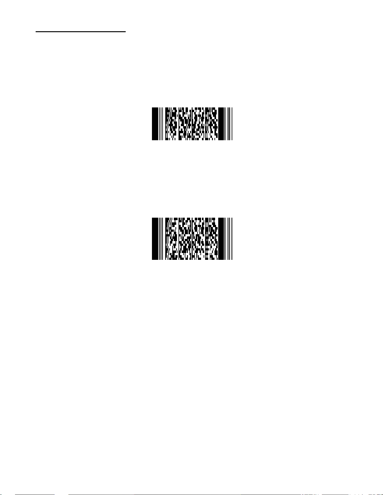
Set to factory default:
To set the scanner to factory defaults, scan one of the codes below.
Set USB I/F and Reset All Settings to Default
Set RS-232 I/F and Reset All Settings to Default
Note: The RS-232 I/F setting applies to the LZ520-2D when used as an external scanner attached to
portable devices such as the Terminal and TriCoder.
Warning: These setup codes are for the LZ520-2D only. Do not use these codes to setup the 2D
scanner on a 2D integrated Terminal or TriCoder. Use the internal menu to configure those
units.
A-3
Page 10
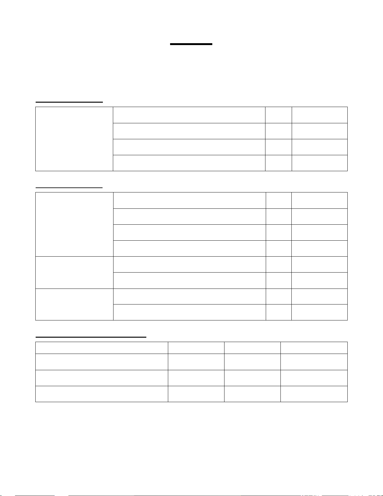
UPC
Start Setup End Setup
[[ [[
UPC-A Settings:
UPC-A
leading zero
check digit transmission
UPC-E Settings:
UPC-E
leading zero
check digit transmission
UPC-A, no leading zero, transmit check digit default
UPC-A, no leading zero, not transmit check digit
UPC-A, leading zero, transmit check digit
UPC-A, leading zero, not transmit check digit
UPC-E, no leading zero, transmit check digit default
UPC-E, no leading zero, not transmit check digit
UPC-E, leading zero, transmit check digit
UPC-E, leading zero, not transmit check digit
F!
F6
F3
F5
F8
F:
F7
F9
transmit UPC-E default
UPC-A,E conversion
transmit as UPC-A
disable UPC-E1 default
UPC-E1 conversion
enable UPC-E1
UPC Supplement Settings:
UPC Symbologies Exclusive Enable Disable
UPC without supplement (default enable)
UPC with 2-digit supplement
UPC with 5-digit supplement
note: setting any symbology to exclusive will disable all other symbologies
K2
K3
K!
A-4
S2
S3
S!
7R
7Q
LQ
LR
Y5C
Y5D
Y5E
Page 11
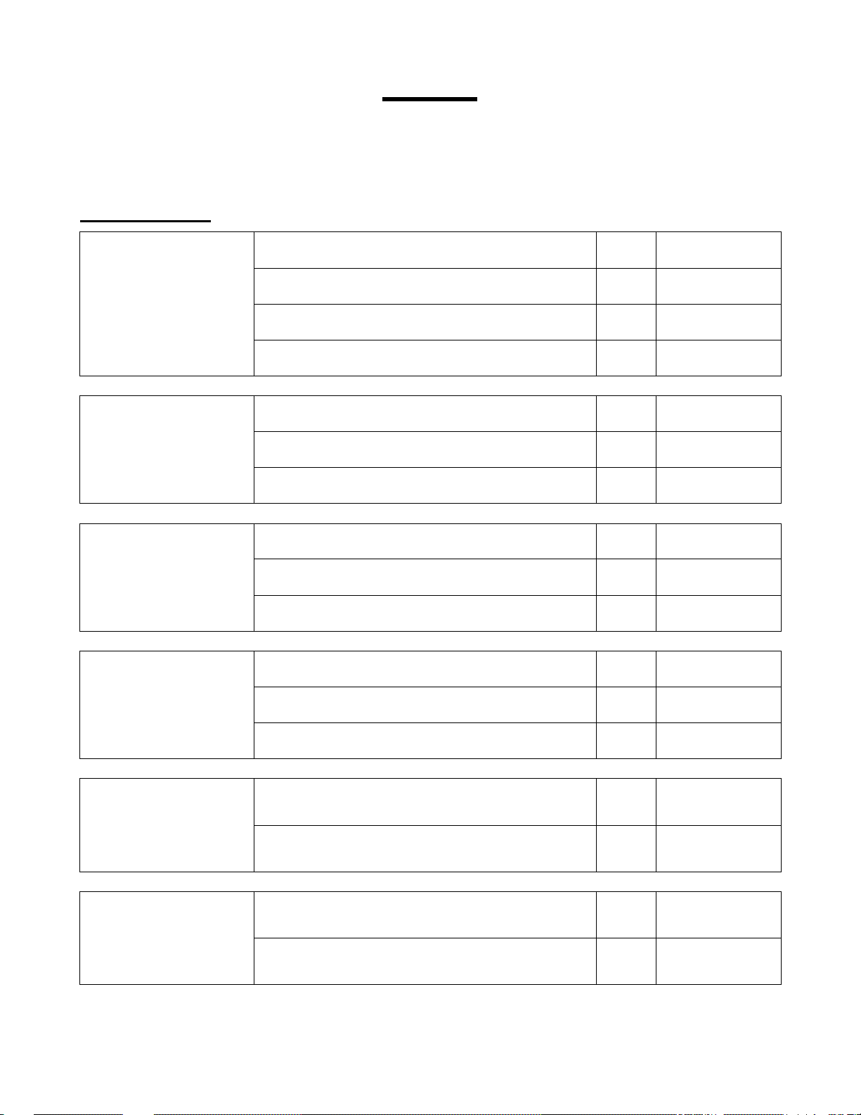
EAN
Start Setup End Setup
[[ [[
EAN Settings:
EAN-13 and EAN-8
Check Digit
Transmission
EAN-13 and EAN-8
ISBN Conversion
EAN-13 and EAN-8
ISSN Conversion
not transmit EAN-13 check digit
transmit EAN-13 check digit default
not transmit EAN-8 check digit
transmit EAN-8 check digit default
disable ISBN conversion default
enable ISBN conversion
enable ISBN if possible
disable ISSN conversion default
enable ISSN conversion
7K
7L
7I
7J
JC
JB
JL
IO
IP
EAN-13 and EAN-8
ISMN Conversion
EAN-13
Forced Add-On 1
EAN-13
Forced Add-On 2
enable ISSN if possible
disable ISMN conversion default
enable ISMN conversion
enable ISMN if possible
enable EAN forced add-on when EAN13 starts
with 378 / 379 / 529
disable EAN forced add-on when EAN13 starts
with 378 / 379 / 529
enable EAN forced add-on when EAN13 starts
with 434 / 439 / 414 / 419 / 977 / 978
disable EAN forced add-on when EAN13 starts
with 434 / 439 / 414 / 419 / 977 / 978
A-5
default
default
5W
JP
JQ
JR
.H
.I
.D
.E
Page 12
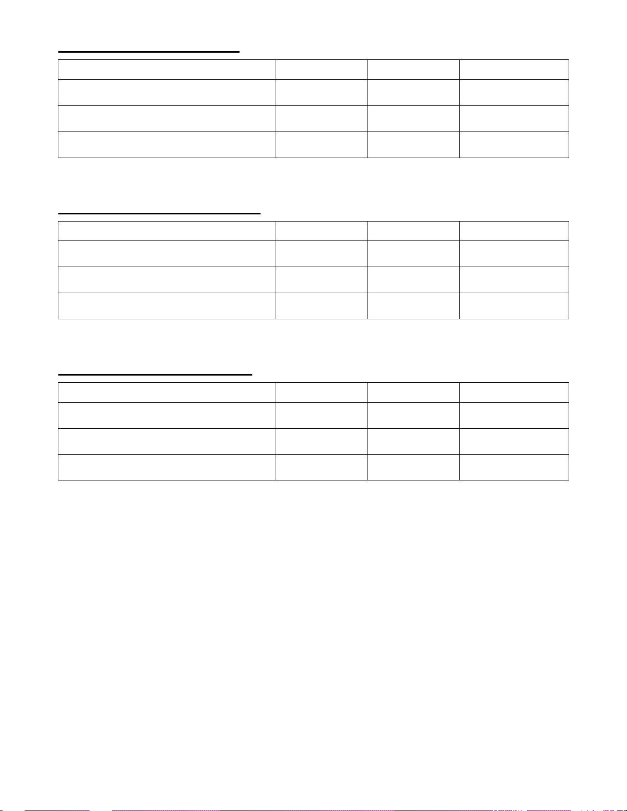
EAN Supplement Settings:
EAN Symbologies Exclusive Enable Disable
EAN no supplement (default enable)
EAN with 2-digit supplement
EAN with 5-digit supplement
note: setting any symbology to exclusive will disable all other symbologies
EAN-13 Supplement Settings:
EAN Symbologies Exclusive Enable Disable
EAN-13 no supplement (default enable)
EAN-13 with 2-digit supplement
EAN-13 with 5-digit supplement
note: setting any symbology to exclusive will disable all other symbologies
EAN-8 Supplement Settings:
K5
K6
K7
KH
KI
KJ
S5
S6
S7
KV
KW
KX
Y5F
Y5G
Y5H
N/A
N/A
N/A
EAN Symbologies Exclusive Enable Disable
EAN-8 no supplement (default enable)
EAN-8 with 2-digit supplement
EAN-8 with 5-digit supplement
note: setting any symbology to exclusive will disable all other symbologies
KB
KC
KD
A-6
KP
KQ
KR
N/A
N/A
N/A
Page 13
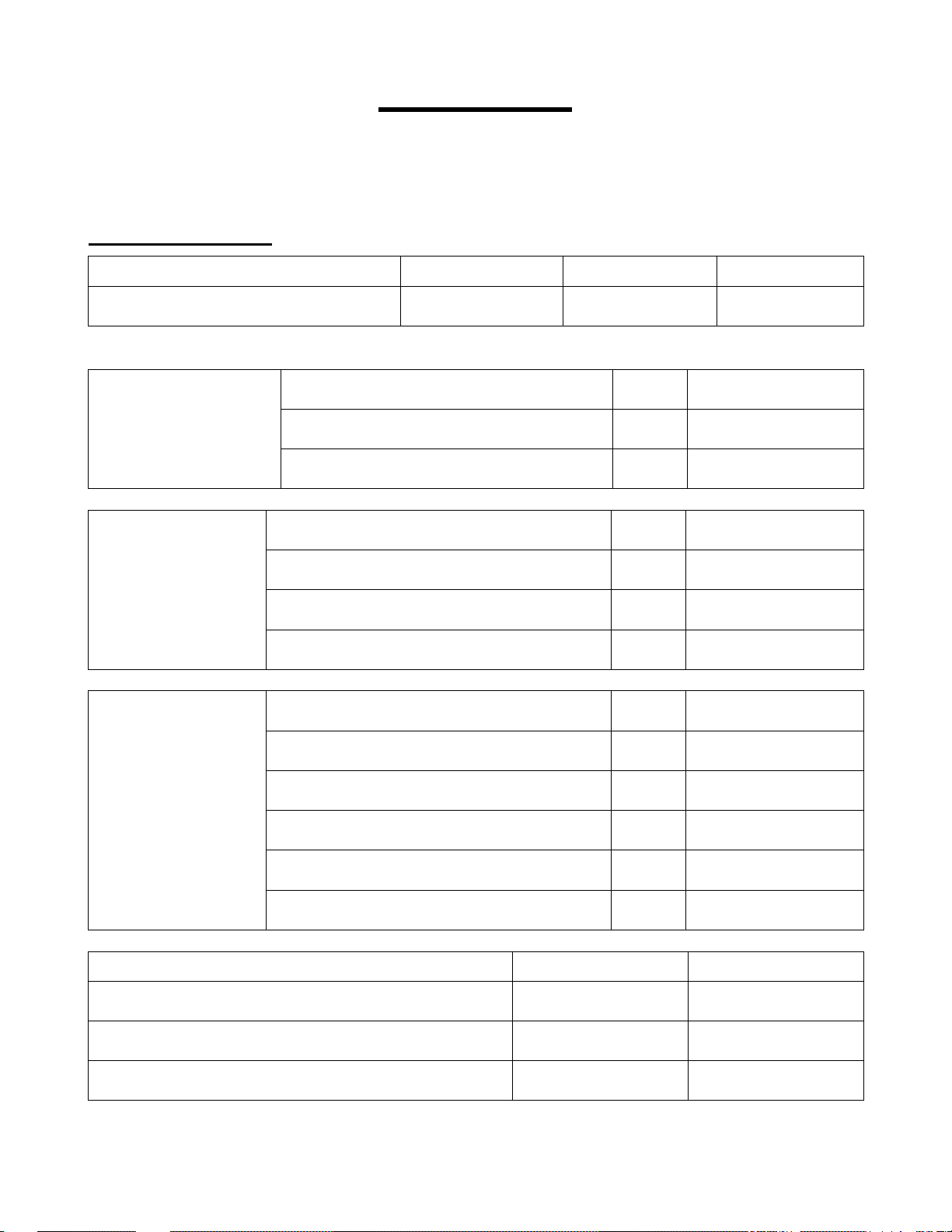
Code 39
Start Setup End Setup
[[ [[
Code 39 Settings:
Code 39 Exclusive Enable Disable
Code 39 Enable/Disable (default enable)
note: setting any symbology to exclusive will disable all other symbologies
normal code 39 default
Full ASCII Conversion
Code 39 and
It Pharmaceutical
Check Digit (CD)
full ASCII code 39
full ASCII code 39 if possible
not check CD default
check CD
not transmit CD
B3
C3
WC
E6
E5
,L
D2
D1
E9
transmit CD default
not transmit start/stop default
transmit start/stop
Code 39 and
It Pharmaceutical
Misc Settings
Italian Pharmaceutical Options Enable Disable
Italian Pharmaceutical Only (default disable)
Italian Pharmaceutical if Possible (default disable)
Leading A Transmission (default disable)
minimum data = three characters
minimum data = one character default
disable concatenation default
enable concatenation
A-7
E7
E8
EC
E:
E2
E1
9E
9F
,N
,M
E6
E6
EB
Page 14
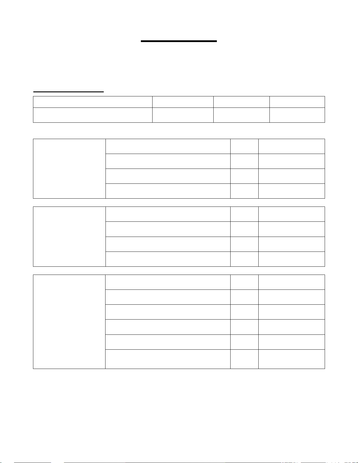
Codabar
Start Setup End Setup
[[ [[
Codabar Settings:
Codabar Exclusive Enable Disable
Codabar Enable/Disable (default enable)
note: setting any symbology to exclusive will disable all other symbologies
enable only Codabar normal mode default
Codabar
ABC, CX Conversion
Codabar
Check Digit (CD)
enable only ABC code
enable only CX code
enable Codabar / ABC and CX
not check CD default
check CD
not transmit CD
B!
C!
WD
IB
I5
I6
I!
I8
I7
I:
Codabar
Start / Stop
transmit CD default
not transmit start / stop default
start / stop = ABCD / ABCD
start / stop = abcd / abcd
start / stop = ABCD / TN*E
start / stop = abcd / tn*e
start = <DC1><DC2><DC3><DC4>
stop = <DC1><DC2><DC3><DC4>
A-8
I9
G1
G!
G5
G2
G3
IK
Page 15
Codabar Settings Continued:
Codabar
Minimum Digit
Codabar
Space Insertion
Codabar
Inter-Character
Gap Check
minimum data = one character
minimum data = three characters
minimum data = five characters default
disable space insertion default
enable space insertion
disable inter-character gap check
enable inter-character gap check default
A-9
ID
IC
IG
IF
IE
IJ
II
Page 16
Code 128
Start Setup End Setup
[[ [[
Code 128 Settings:
Codabar Exclusive Enable Disable
Code 128 Enable/Disable (default enable)
note: setting any symbology to exclusive will disable all other symbologies
disable GS1-128 default
Code 128 and
GS1-128 (EAN-128)
EAN-128 Conversion
Code 128 and
GS1-128 (EAN-128)
Concatenation
enable GS1-128 only
enable EAN-128 if possible
disable concatenation (FNC2 message append) default
enable concatenation (FNC2 message append)
B7
A-10
C7
WF
PG
KG
PH
NQ
NP
Page 17
Code 93
Start Setup End Setup
[[ [[
Code 93 Settings:
Symbology Exclusive Enable Disable
Code 93 (default enable)
note: setting any symbology to exclusive will disable all other symbologies
Code 93
Check Digit (CD)
not transmit CD default
transmit CD
B6
A-11
C6
WE
E[
EZ
Page 18
Code 11
Start Setup End Setup
[[ [[
Code 11 Settings:
Symbology Exclusive Enable Disable
Code 11 (default disable)
note: setting any symbology to exclusive will disable all other symbologies
not check CD
check 1 CD
Code 11
Check Digit (CD)
check 2 CD
check auto 1 or 2 CD default
not transmit CD default
transmit CD
CMC
A-12
CMD
CMB
CMG
CMH
CMI
CMJ
CMK
CML
Page 19
2 of 5 and S-Code
Start Setup End Setup
[[ [[
2 of 5 and S-Code Settings:
Symbology Exclusive Enable Disable
Industrial 2 of 5 (default enable)
Interleaved 2 of 5 (default enable)
S-Code (default enable)
Matrix 2 of 5 (default disable)
Chinese Post Matrix 2 of 5
(default disable)
note: setting any symbology to exclusive will disable all other symbologies
not check CD default
2 of 5 and S-Code
Check Digit (CD)
check CD
not transmit CD
K8
K9
SB
BC
KF
S8
S9
S:
CC
KT
Y5L
Y5M
N/A
N/A
KU
H1
H2
F2
2 of 5 and S-Code
Space Check
S-Code Conversion
2 of 5 and S-Code
Minimum Digit
transmit CD default
disable space check for Industrial 2 of 5
enable space check for Industrial 2 of 5 default
not transmit S-Code as Interleaved 2 of 5 default
transmit S-Code as Interleaved 2 of 5
minimum data = one character
minimum data = three characters
minimum data = five characters default
A-13
F1
HL
HK
HI
HH
HF
HG
HJ
Page 20
MSI / Plessey
Start Setup End Setup
[[ [[
MSI / Plessey Settings:
Symbology Exclusive Enable Disable
MSI / Plessey (default enable)
note: setting any symbology to exclusive will disable all other symbologies
not check CD
check 1 CD = mod 10 default
MSI / Plessey
Check Digit (CD)
check 2 CD = mod 10/mod 10
check 2 CD = mod 10/mod 11
check 2 CD = mod 11/mod 10
check 2 CD = mod 11/mod 11
B8
C8
WG
5B
5C
5D
5E
5S
5T
MSI / Plessey
Check Digit (CD)
Transmission
not transmit CD
transmit CD 1 default
transmit CD 1 and CD 2
A-14
5H
5F
5G
Page 21
UK / Plessey
Start Setup End Setup
[[ [[
UK / Plessey Settings:
Symbology Exclusive Enable Disable
UK / Plessey (default enable)
note: setting any symbology to exclusive will disable all other symbologies
UK / Plessey
Check Digit (CD)
UK / Plessey
Space Insertion
UK / Plessey
X Conversion
not transmit CD
transmit CD default
disable space insertion default
enable space insertion
disable A -> X conversion default
enable A -> X conversion
B2
A-15
C2
WB
5P
5O
EP
EO
EQ
ER
Page 22
POSTNET
Start Setup End Setup
[[ [[
POSTNET Settings:
Symbology Exclusive Enable Disable
POSTNET (default disable)
note: setting any symbology to exclusive will disable all other symbologies
E7D
A-16
E7B
E7C
Page 23
Intelligent Mail Bar Code
Start Setup End Setup
[[ [[
Intelligent Mail Bar Code Settings:
Symbology Exclusive Enable Disable
IMBC (default disable)
note: setting any symbology to exclusive will disable all other symbologies
E6I
A-17
E6G
E6H
Page 24
GS1 DataBar
Start Setup End Setup
[[ [[
GS1 DataBar Settings:
Symbology Exclusive Enable Disable
GS1 DataBar
Omnidirectional
Truncated
Stacked
Stacked Omnidirectional
(default enable)
GS1 DataBar Limited
(default enable)
GS1 DataBar
Expanded
Expanded Stacked
(default enable)
GS1 DataBar
All Above Types
(default enable)
note: setting any symbology to exclusive will disable all other symbologies
K:
KK
KL
CD7
KY
KZ
ES
CDJ
TK
TL
TM
CDV
GS1 DataBar
Check Digit (CD)
GS1 DataBar
AI Transmission
not transmit CD
transmit CD default
not transmit application identifier
transmit application identifier default
A-18
EN
EM
EU
ET
Page 25
Korean Postal Authority
Start Setup End Setup
[[ [[
Korean Postal Authority Code Settings:
Symbology Exclusive Enable Disable
Korean Postal Authority
(default disable)
note: setting any symbology to exclusive will disable all other symbologies
Korean Postal Authority
Check Digit (CD)
Korean Postal Authority
Dash
Korean Postal Authority
Upside Down Reading
KM
not transmit CD default
transmit CD
not transmit dash
transmit dash default
upside down reading enabled
upside down reading disabled default
A-19
XI
XJ
+.
+,
+0
+/
+:
+9
Page 26
IATA
Start Setup End Setup
[[ [[
IATA Settings:
Symbology Exclusive Enable Disable
IATA (default enable)
note: setting any symbology to exclusive will disable all other symbologies
not check CD default
IATA
Check Digit (CD)
IATA
Check Digit (CD)
Transmission
check FC / SN only
check FC / CPN / SN
check FC / CPN / AC / SN
not transmit CD
transmit CD default
B5
C5
A-20
WI
5I
5J
5K
5L
5N
5M
Page 27
Tri-Optic
Start Setup End Setup
[[ [[
Tri-Optic Settings:
Symbology Exclusive Enable Disable
Tri-Optic (default enable)
note: setting any symbology to exclusive will disable all other symbologies
KE
K[
A-21
N/A
Page 28
Telepen
Start Setup End Setup
[[ [[
Telepen Settings:
Symbology Exclusive Enable Disable
Telepen (default enable)
note: setting any symbology to exclusive will disable all other symbologies
Telepen Conversion
Output Mode
numeric mode default
ASCII mode
B:
C:
A-22
WH
E3
E!
Page 29
JPN (Customer Bar Code)
Start Setup End Setup
[[ [[
JPN Settings:
Symbology Exclusive Enable Disable
JPN (default disable)
note: setting any symbology to exclusive will disable all other symbologies
E6S
A-23
E6Q
E6R
Page 30
PDF417
Start Setup End Setup
[[ [[
PDF417 Settings:
Symbology Exclusive Enable Disable
PDF417 (default enable)
note: setting any symbology to exclusive will disable all other symbologies
CD!
A-24
CDG
CDS
Page 31
Micro PDF417
Start Setup End Setup
[[ [[
Micro PDF417 Settings:
Symbology Exclusive Enable Disable
Micro PDF417 (default enable)
note: setting any symbology to exclusive will disable all other symbologies
CD5
A-25
CDH
CDT
Page 32
Maxi Code
Start Setup End Setup
[[ [[
Maxi Code Settings:
Symbology Exclusive Enable Disable
Maxi Code (default enable)
note: setting any symbology to exclusive will disable all other symbologies
CD3
A-26
CDF
CDR
Page 33
QR Code
Start Setup End Setup
[[ [[
QR Code Settings:
Symbology Exclusive Enable Disable
QR Code (default enable)
note: setting any symbology to exclusive will disable all other symbologies
CD2
A-27
CDE
CDQ
Page 34
Micro QR
Start Setup End Setup
[[ [[
Micro QR Settings:
Symbology Exclusive Enable Disable
Micro QR (default enable)
note: setting any symbology to exclusive will disable all other symbologies
E!9
A-28
E3V
E3W
Page 35
Aztec Code
Start Setup End Setup
[[ [[
Aztec Code Settings:
Symbology Exclusive Enable Disable
Aztec Code (default enable)
note: setting any symbology to exclusive will disable all other symbologies
CD6
A-29
CDI
CDU
Page 36
Aztec Runes
Start Setup End Setup
[[ [[
Aztec Runes Settings:
Symbology Exclusive Enable Disable
Aztec Runes (default disable)
note: setting any symbology to exclusive will disable all other symbologies
CG5
A-30
CG3
CG!
Page 37
Data Matrix
Start Setup End Setup
[[ [[
Data Matrix Settings:
Symbology Exclusive Enable Disable
Data Matrix (ECC 200)
(default enable)
Data Matrix (ECC 000-140)
(default disable)
note: setting any symbology to exclusive will disable all other symbologies
CD1
CH3
A-31
CDD
CH1
CDP
CH2
Page 38
Codablock F
Start Setup End Setup
[[ [[
Codablock F Settings:
Symbology Exclusive Enable Disable
Codablock F (default disable)
note: setting any symbology to exclusive will disable all other symbologies
E5S
A-32
E5Q
E5R
Page 39
Chinese Sensible Code
Start Setup End Setup
[[ [[
Chinese Sensible Code Settings:
Symbology Exclusive Enable Disable
Chinese Sensible Code
(default disable)
note: setting any symbology to exclusive will disable all other symbologies
E5L
A-33
E5M
E5N
Page 40
All Codes
Start Setup End Setup
[[ [[
All Codes Settings:
Symbology Exclusive Enable Disable
All 1D Codes (default disable)
All 2D Codes (default disable)
All 1D and 2D Codes
(default disable)
note: setting any symbology to exclusive will disable all other symbologies
Use this setting if you're having trouble reading a bar code with the default settings and you don't know
what type of code you are trying to read. It's also a quick way to turn On or Off all 1D or 2D code
symbologies.
CDB
CDC
B1
A-34
CDN
CDO
CDZ
CD[
C1
Page 41
Number of Characters
Start Setup End Setup
[[ [[
Number of Characters Settings:
If you are going to read bar codes of a known length, it is recommended to set the scanner for a fixed
number of characters. The scanner uses this to verify that labels read are of the correct length and
reject labels that do not have the specified length. The advantage of setting a fixed length is that it
provides protection against short scans of labels, such as Interleaved 2of 5, which do not provide
sufficient security against partial scans. The length check is done on the label data and is not affected
by options such as (not) transmit start/stop character or check digit. Setting the number or characters
does not affect fixed length codes, such as EAN-13. It is also possible to set the minimum and
maximum number of characters allowed. The character length settings can be global (applying to all
enabled codes) or individual (applying only to selected code types).
Character Length Settings:
Global Setting
for Fixed Length
Individual Setting
for Length
fixed length OFF for all variable length codes default
fixed length ON for all enabled variable length codes
fixed length ON for selected variable length code(s)
set minimum length for selected variable length code(s)
I1
I2
IL
IM
set maximum length for selected variable length codes
Fixed Length Example Programming Sequence:
1) Scan “Start Setup”
2) Scan “Fixed Length ON” (global or individual)
3) Scan a bar code of the desired length
4) Scan another bar code of a second desired length (optional)
5) Scan “End Setup”
If you scan “global” fixed length then all enabled codes will be affected. If you scan
“individual” fixed length then only the symbology scanned in step 3 and/or 4 is affected.
Note: The maximum number of characters that can be set is 8000.
A-35
IN
Page 42
Composite Codes
Start Setup End Setup
[[ [[
Composite Codes Settings:
not ignore link flag for RSS/EAN-128 and EAN/UPC default
Link Flag
ignore link flag for RSS/EAN-128 and EAN/UPC
RSS / EAN-128
Composite
EAN / UPC
Composite
Composite
Component
disable RSS/EAN-128 composite default
enable RSS/EAN-128 composite
disable EAN/UPC composite default
enable EAN/UPC composite
enable 1D composite only
enable 2D composite only
SR
SQ
CIG
CIF
E2X
E2W
CM1
CM2
enable 1D and 2D composites default
Outputs for Composite Code Setting:
Composite Setting Output
Enable/Disable Link Flag Composite Component 1D+2D
not ignore N/A o x x
Enable
ignore
Disable N/A
o : Priority output
# : Output when data cannot be output with o
x : Not output
1D composite only o # x
2D composite only o x #
1D and 2D composite o # #
1D composite only x o x
2D composite only x x o
1D and 2D composite x o o
A-36
CM3
1D 2D
Page 43
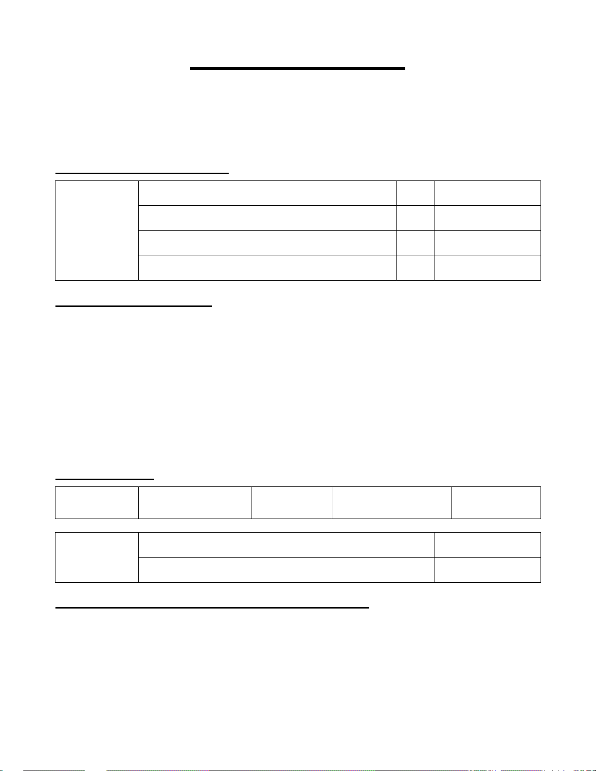
String Options
Start Setup End Setup
[[ [[
Case Conversion Settings:
no case conversion (AbCd -> AbCd) default
Case
Conversion
Output Format Settings:
The following additional characters can be included in each code that is scanned:
1) Preamble / Postamble (up to 8 digits)
Specified strings can be added in front and at the end of the data for all codes.
2) Prefix / Suffix (up to 4 digits)
Specified strings can be added in front and at the end of the data for a specific symbology.
By default, the prefix is empty and the suffix is a CR character.
3) Code Identification / Code Length
Code Identification and Code Length can be included in a prefix and/or a suffix.
convert to upper case (AbCd -> ABCD)
convert to lower case (AbCd -> abcd)
exchange case (AbCd -> aBcD)
Z[
ZX
ZY
ZZ
Output Format:
Preamble
(max 8 digits)
Preamble and
Postamble
Preamble / Postamble Example Programming Sequence:
1) Scan “Start Setup”
2) Scan “Preamble Command” or “Postamble Command”
3) Scan up to 8 ASCII values from the ASCII Value Table
4) Scan “End Setup”
Prefix for each code
(max 4 digits)
preamble command
postamble command
Data
A-37
Suffix for each code
(max 4 digits)
Postamble
(max 8 digits)
N[
QT
Page 44
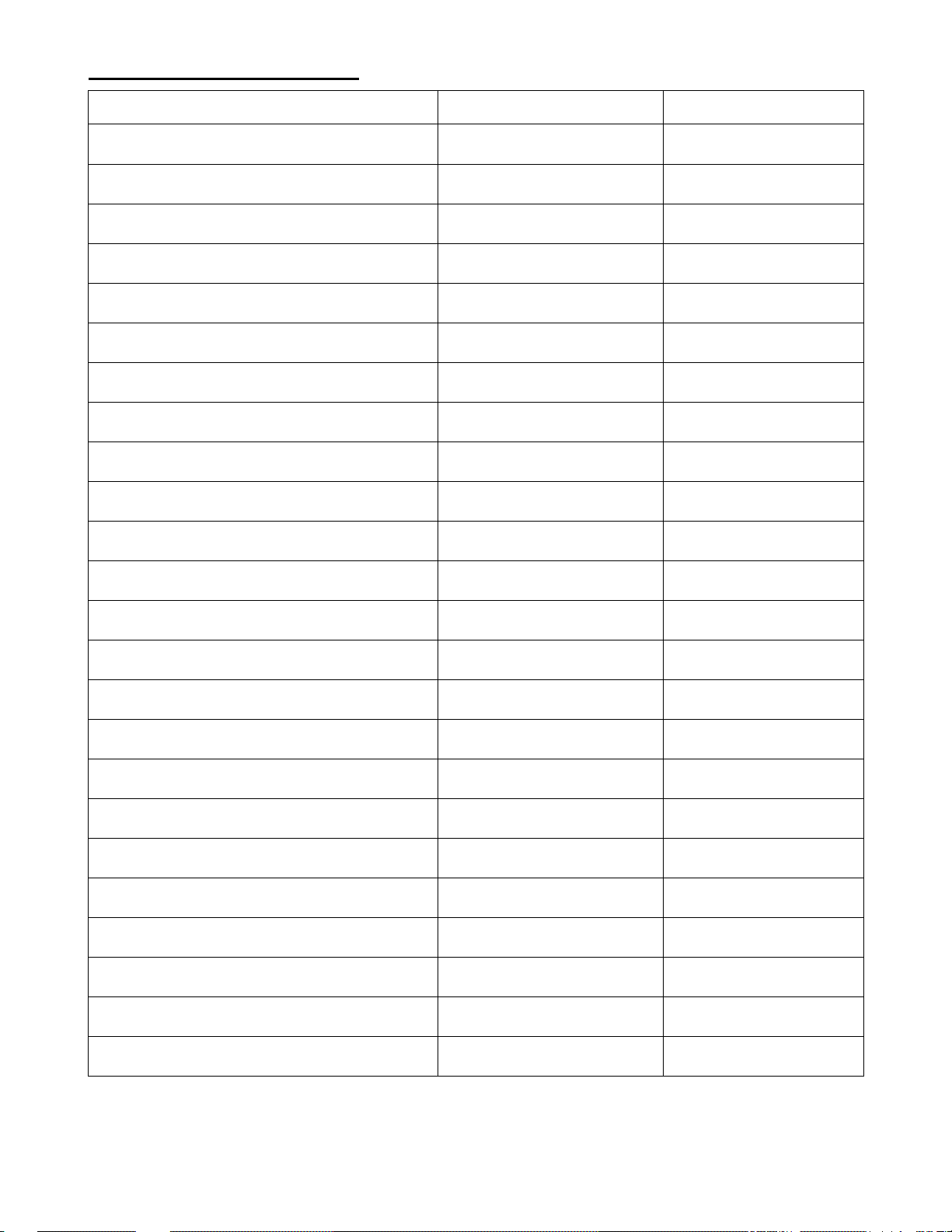
Prefix / Suffix Commands:
Symbology Prefix Command Suffix Command
All Codes
UPC-A
UPC-A add-on
UPC-E
UPC-E add-on
EAN-13
EAN-13 add-on
EAN-8
EAN-8 add-on
Code 39
Tri-optic
Codabar
SZ
O2
N1
O3
N2
O!
N3
O5
N!
N5
ND
N6
S[
O7
P1
O8
P2
O9
P3
O:
P!
P5
QO
P6
Industrial 2 of 5
Interleaved 2 of 5
S-code
Matrix 2 of 5
IATA
MSI/Plessey
Telepen
UK/Plessey
Code 128
GS1-128
Code 11
Intelligent Mail Bar Code
N7
N8
NC
HM
J9
O1
M9
NB
N:
YNY
CME
E6J
P7
P8
PC
HN
J:
O6
M:
PB
P:
YPY
CMF
E6K
A-38
Page 45
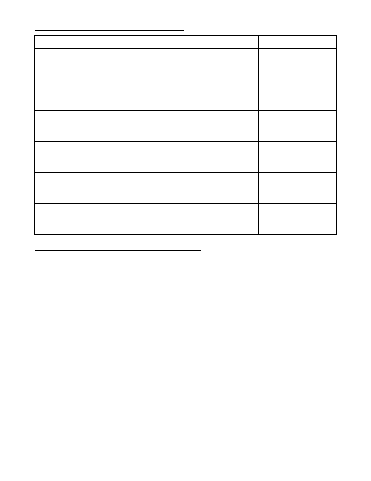
Prefix / Suffix Commands Continued:
Symbology Prefix Command Suffix Command
POSTNET
GS1 DataBar
Composite code
Codablock-F
Data Matrix
Aztec
Chinese Sensible Code
QR Code
Maxicode
PDF417
MicroPDF417
Clear Prefix / Suffix
Prefix / Suffix Example Programming Sequence:
1) Scan “Start Setup”
2) Scan “Prefix Command” or “Suffix Command” for the desired symbology
3) Scan up to 4 ASCII values from the Prefix / Suffix ASCII Value Table
4) Scan “End Setup”
E7E
PF
SS
E5T
NE
CG1
E5O
NL
NM
PD
PE
NH
A-39
E7F
QR
ST
E5U
QP
CG2
E5P
QX
QY
QZ
Q[
QS
Page 46

Prefix / Suffix ASCII Value Table:
6B
A 1B
a %
B
:H
6C
B 1C
b %
C
2B
6D
C 1D
c %
D
2C
6E
D 1E
d %
E
2D
6F
E 1F
e %
F
2E
6G
F 1G
f %
G
2F
6H
G 1H
g %
H
2G
6I
H 1I
h %
I
2H
6J
I 1J
i %
J
2I
6K
J 1K
j %
K
2J
6L
K 1L
k %
L
2K
6M
L 1M
l %
M
2L
6N
M 1N
m %
N
2M
6O
N 1O
n %
O
2N
6P
O 1P
o %
P
2O
6Q
P 1Q
p %
Q
2P
7B
Q 1R
q %
R
2Q
7C
R 1S
r %
S
2R
7D
S 1T
s %
T
2S
7E
T 1U
t %
U
2T
7F
U 1V
u %
V
2U
7G
V 1W
v %
W
2V
7H
W 1X
w %
X
2W
8B
X 1Y
x %
Y
2X
8C
Y 1Z
y %
Z
2Y
8D
Z 1[
z %
[
2Z
ASCII Command ASCII Command ASCII Command ASCII Command
<SP>
!
“
#
$
%
&
'
(
)
*
+
,
-
(NULL)
(SOH)
(STX)
(ETX)
(EOT)
(ENQ)
(ACK)
(BEL)
(BS)
(HT)
(LF)
(VT)
(FF)
(CR)
.
/
:
;
<
=
>
?
@
[
\
]
(SO)
(SI)
(DLE)
(DC1)
(DC2)
(DC3)
(DC4)
(NAK)
(SYN)
(ETB)
(CAN)
(EM)
A-40
Page 47
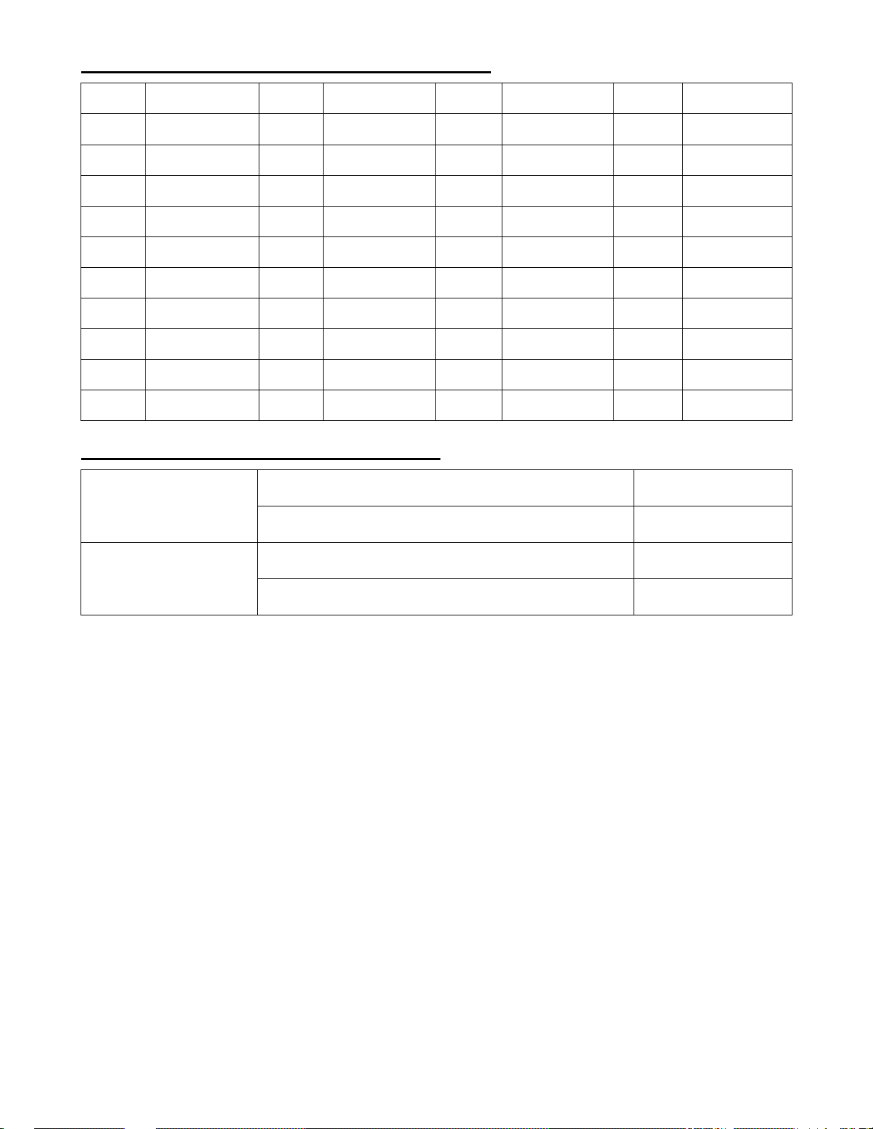
Prefix / Suffix ASCII Value Table Continued:
8E
0 R1
2[
8F
1 R2
:B
8G
2 R3
:C
:U
3 R!
:D
:V
4 R5
:E
:W
5 R6
:F
:X
6 R7
:G
R8
R9
R:
ASCII Command ASCII Command ASCII Command ASCII Command
^
_
`
{
|
}
~
7
8
9
Code Identification / Length Settings:
code identification using Worth Data Code ID
Code Identification
code identification using AIM/ISO/IEC 15424 ID
(SUB)
(ESC)
(FS)
(GS)
(RS)
(US)
DEL
%3
%2
code length (1D/2D : 2/6 digit)
Code Length
code length (1D/2D : 6/6 digit)
Code Identification and Code Length can be included in a prefix and/or suffix. The code length will be
the number of characters that is configured above. The code identification and code length can be put
at any position in the prefix/suffix string. These direct input characters count as 1 entry of the 4
permissible entries for a prefix and suffix.
The code length is transmitted as 2 digits, excluding prefix and suffix characters. For 2D codes the
code length is transmitted as 6 digits. It is also possible to send the length as 6 digits for both 1D and
2D codes.
A-41
%!
%7
Page 48

Worth Data Code ID Prefix / Suffix Values:
Code Code ID Code Code ID
UPC-A C MSI/Plessey Z
UPC-A +2 F Telepen d
UPC-A +5 G UK/Plessey a
UPC-E D Code 128 T
UPC-E +2 H GS1-128 T
UPC-E +5 I Code 93 U
EAN-13 B Code 11 b
EAN-13 +2 L Korean Postal Authority c
EAN-13 +5 M Intelligent Mail Bar Code 0
EAN-8 A POSTNET 3
EAN-8 +2 J GS1 DataBar y
EAN-8 +5 K Composite Code-A m
Code 39 V Composite Code-B n
Code 39 Full ASCII W Composite Code-C l
Italian Pharmaceutical Y Codablock-F E
Codabar R DataMatrix t
Codabar ABC S Aztec o
Codabar CX f Aztec Runes o
Industrial 2 of 5 O Chinese Sensible Code e
Interleaved 2 of 5 N QR Code u
S-Code g Micro QR Code j
Matrix 2 of 5 Q Maxi Code v
Chinese Post w PDF417 r
IATA P Micro PDF417 s
A-42
Page 49
Collective Reading
Start Setup End Setup
[[ [[
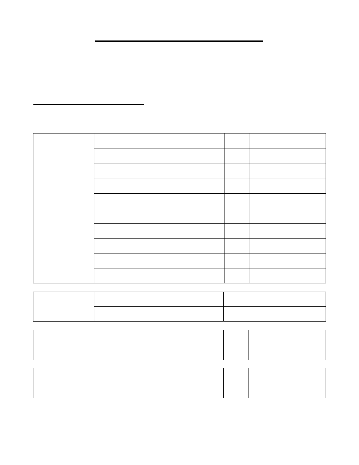
Collective Reading Settings:
It is possible to not output data unless the specified number of codes is read. That means that the
scanner does not read codes other than the specified number. Use this setting to read a group of labels
all at once.
Multiple Label
Read
multiple label = 1 default
multiple label = 2
multiple label = 3
multiple label = 4
multiple label = 5
multiple label = 6
multiple label = 7
multiple label = 8
E12
E13
E1!
E15
E16
E17
E18
E19
Multiple Label
Read
(right and left)
Multiple Label Read
(top and bottom)
Multiple Label Read
(output priority)
multiple label = 9
multiple label = 10
left to right default
right to left
top to bottom default
bottom to top
output priority vertical default
output priority horizontal
A-43
E1:
E1B
E1O
E1P
E1Q
E1R
E1T
E1S
Page 50
Collective Reading Settings Continued:
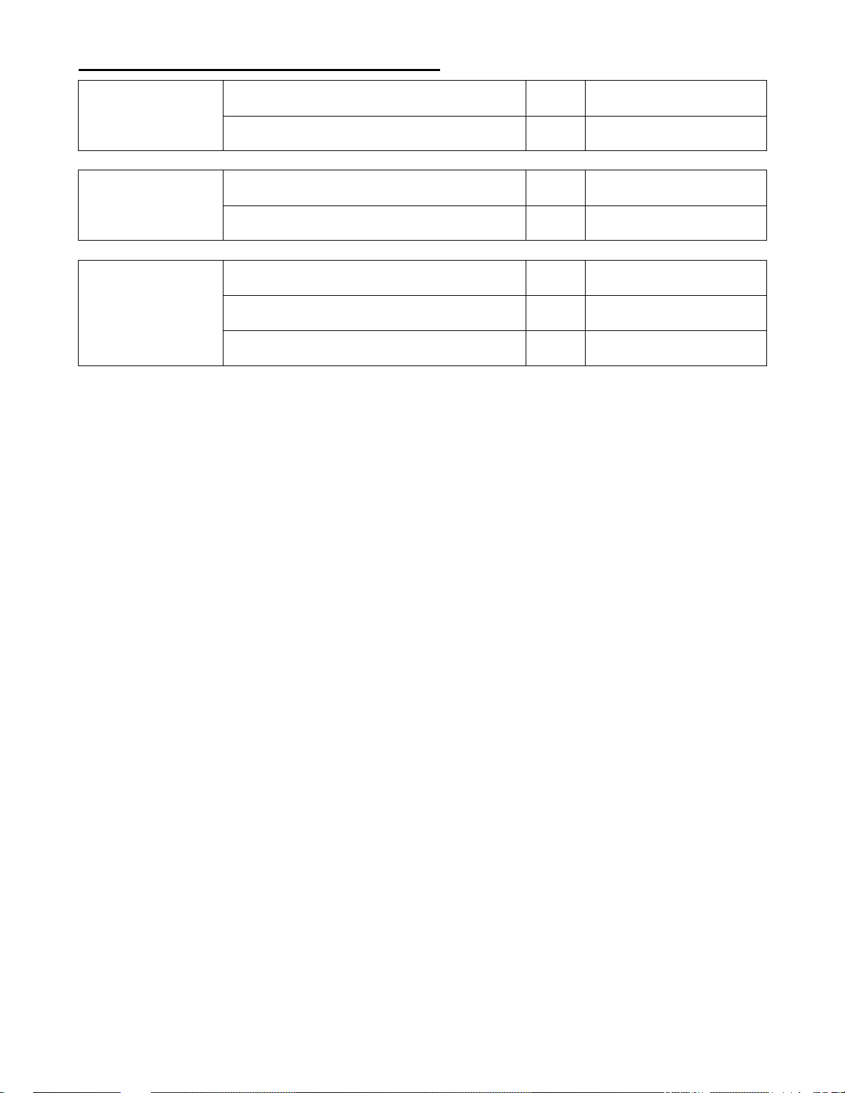
Same Label Read
Sorting Labels
Buffered Mode
disable same label read during multiple read default
enable same label read during multiple read
enable sorting decoded labels default
disable sorting decoded labels
buffered mode (one image) default
buffered mode (multiple images)
non-buffered mode
A-44
E1U
E1V
E1W
E1X
E1Y
E1M
E1Z
Page 51
Read Mode
Start Setup End Setup
[[ [[
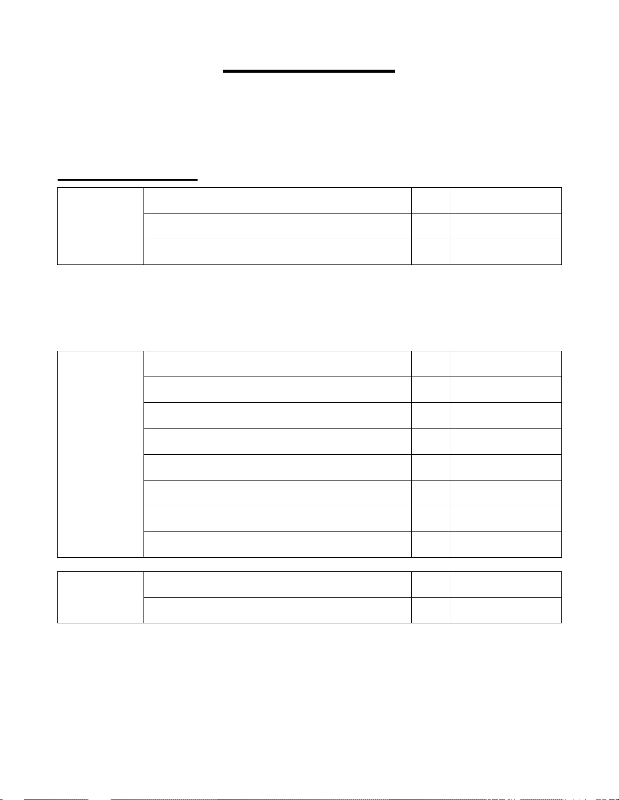
Read Mode Settings:
single read default
Read Mode
In multiple read mode, when a bar code has been decoded, the decoded data will be output and the scan
engine will keep on reading. When the bar code that has just been output is read again, it will not be
output. However, when the scanner cannot decode any labels for some configurable time, it will forget
the previous scan and then the same label can be read again.
multiple read (see below)
continuous read (used mainly for demonstration)
multiple read reset time = 1 frame
multiple read reset time = 2 frames
multiple read reset time = 3 frames
T1
T2
T3
BI
BJ
BK
Multiple Read
Reset Time
Enable/Disable
Trigger
multiple read reset time = 4 frames
multiple read reset time = 5 frames
multiple read reset time = 6 frames default
multiple read reset time = 7 frames
multiple read reset time = indefinitely
enable trigger default
disable trigger (continuous read)
A-45
BL
BM
BN
BO
BH
T9
T8
Page 52
Read Mode Settings Continued:
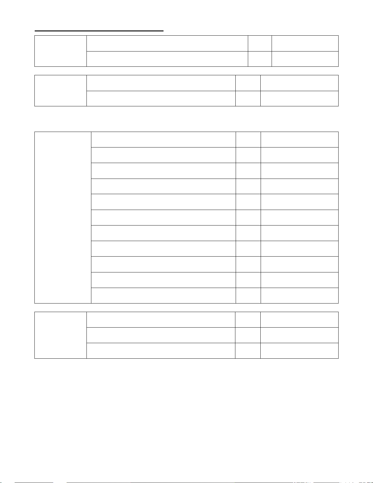
Auto Trigger
(Stand Mode)
Auto Trigger
Synchronization
note: when the auto trigger is synchronized with the trigger switch, the read time configured for normal
reading will be used for auto trigger read time.
Auto Trigger
Read Time
enable auto trigger
disable auto trigger default
disable auto trigger synchronization
enable auto trigger synchronization default
read time 1 second default
read time 2 seconds
read time 3 seconds
read time 4 seconds
read time 5 seconds
read time 6 seconds
,J
,G
&R
&S
&G
&H
&I
&J
&K
&L
Auto Trigger
Conditions
read time 7 seconds
read time 8 seconds
read time 9 seconds
read time * 10
read time indefinitely
auto trigger = sensitive default
auto trigger = normal
auto trigger = insensitive
A-46
&M
&N
&O
&P
&Q
YNG
YNI
YNK
Page 53
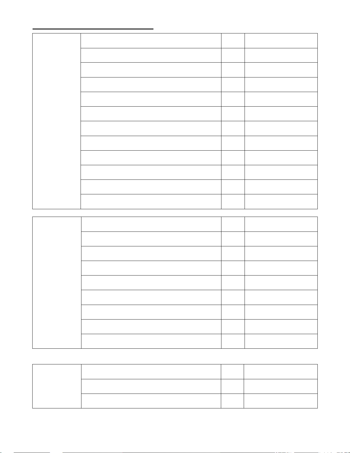
Read Mode Settings Continued:
Normal
Read Time
read time 0 second
read time 1 second
read time 2 seconds default
read time 3 seconds
read time 4 seconds
read time 5 seconds
read time 6 seconds
read time 7 seconds
read time 8 seconds
read time 9 seconds
read time * 10
read time indefinitely
Z1
Z2
Z3
Z!
Z5
Z6
Z7
Z8
Z9
Z:
ZN
ZM
read 1 time, redundancy = 0
read 2 time, redundancy = 1 default
read 3 time, redundancy = 2
read 4 time, redundancy = 3
Redundancy
Redundancy is the number of times that the label has to be scanned in addition to the first scan.
Positive and
Negative Codes
read 5 time, redundancy = 4
read 6 time, redundancy = 5
read 7 time, redundancy = 6
read 8 time, redundancy = 7
read 9 time, redundancy = 8
positive bar codes (black on white) default
negative bar codes (white on black)
Y1
Y2
Y3
Y!
CT
CU
CV
CW
CX
W3
W!
positive and negative bar codes
A-47
W5
Page 54
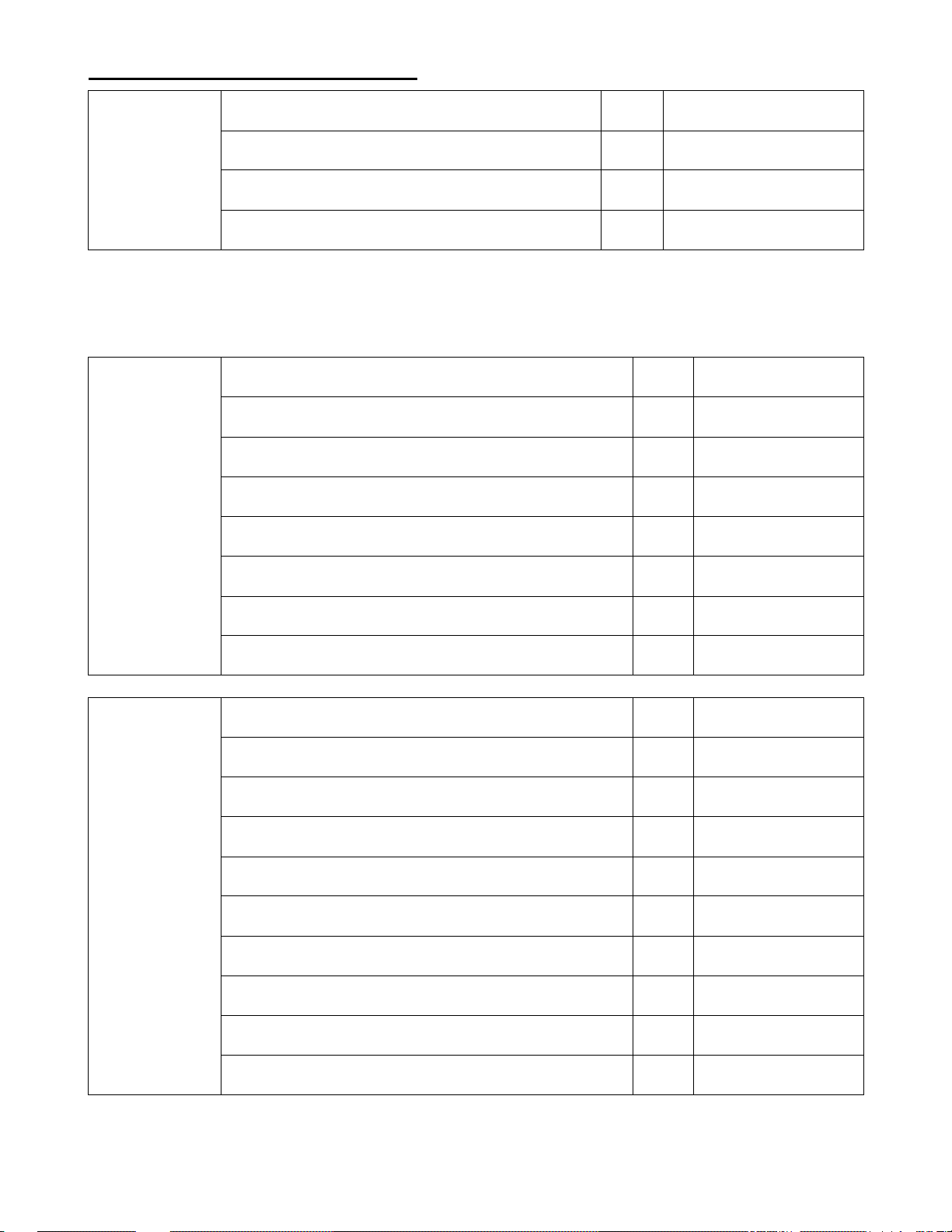
Read Mode Settings Continued:
disable add-on wait more default
Add-on
Delay Timer
Since WPC-type codes (UPC, EAN) with add-on (supplements) have a high probability of
unsuccessful decoding, the scanner repeats decoding the add-on code during the specified period of
time. It is effective to read the add-on parts, but it will also cause a reduced response when a code
without an add-on is read.
Margin Check
(Quiet Zone)
add-on wait mode = 0.25 seconds
add-on wait mode = 0.50 seconds
add-on wait mode = 0.75 seconds
no margin check
margin check 1/7 normal
margin check 2/7 normal
margin check 3/7 normal
margin check 4/7 normal
YB
YC
YD
YE
/ZO
ZP
ZQ
ZR
ZS
Power Saving
margin check 5/7 normal
margin check 6/7 normal
margin check normal default
disable power saving (USB I/F default) default
power saving after 0 seconds (RS-232 I/F default) default
power saving after 1 second
power saving after 2 seconds
power saving after 5 seconds
power saving after 10 seconds
power saving after 30 seconds
power saving after 10 minutes
ZT
ZU
ZV
YTD
F75
YTI
FC1
FC2
FC3
YTE
YTF
power saving after 30 minutes
power saving after 60 minutes
A-48
YTG
YTH
Page 55
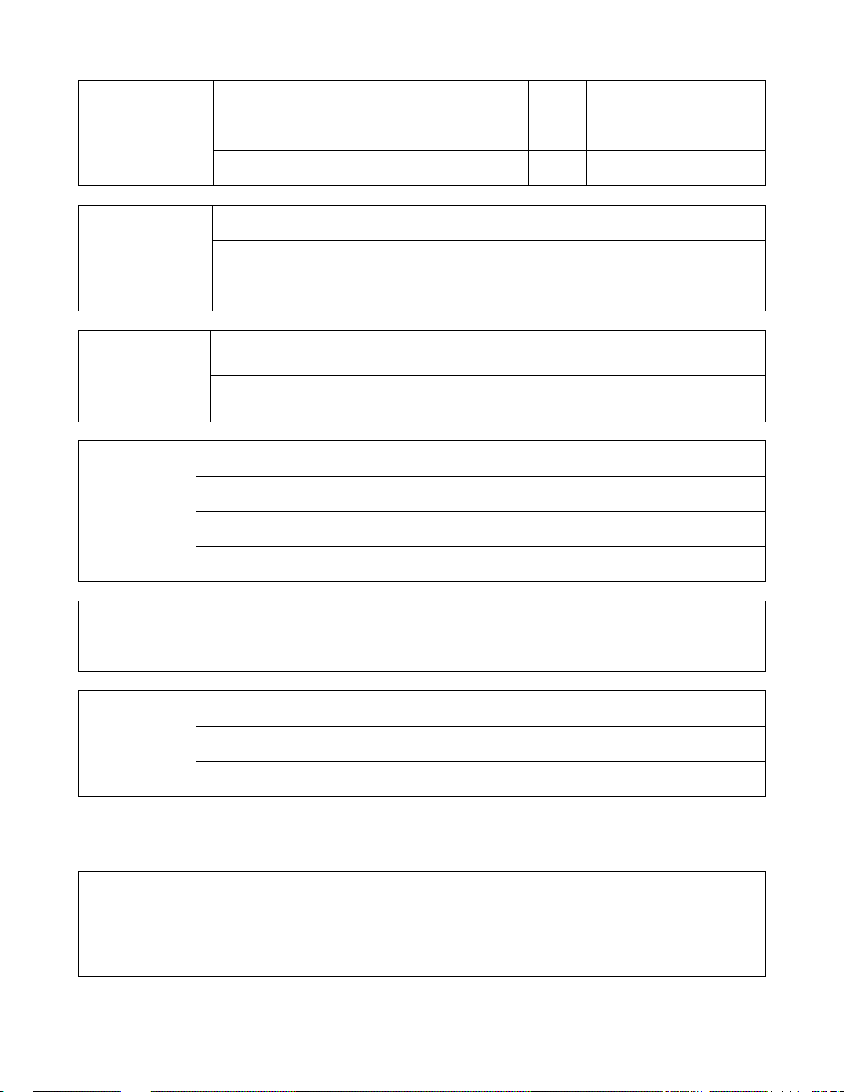
Imager Settings:
Illumination Mode
Aiming On/Off
Central Reading
1D Code
Decode Mode
disable LED illumination
enable LED illumination default
LED illumination alternating
disable laser aiming and LED illumination
enable laser aiming default
disable laser aiming
enable central reading
(read only a code that the laser aims at)
disable central reading
(read the entire image)
careful mode (good for hard to read codes)
standard mode default
semi-quick mode
default
E!B
E!:
E!C
E!D
E!E
E!F
E11
E1[
EN!
EN3
EN2
quick mode (good for easy to read codes)
LCD Display
Scanning
Auto Focus
Mode
Note: Normally laser ranging is used for reading labels. In case it cannot be used in a brightly-lit
environment, the contrast method is used. When “contrast only” is configured, the reading speed will
be slower.
Fixed Focus
Mode
disable scanning from LCD display default
enable scanning from LCD display
AF system = laser and contrast default
AF system = contrast only
AF system = laser only
short range = 90mm
medium range = 163mm
long range = 880mm
A-49
EN1
E!J
E!K
F9L
F9M
F9N
F9O
F9P
F9Q
Page 56
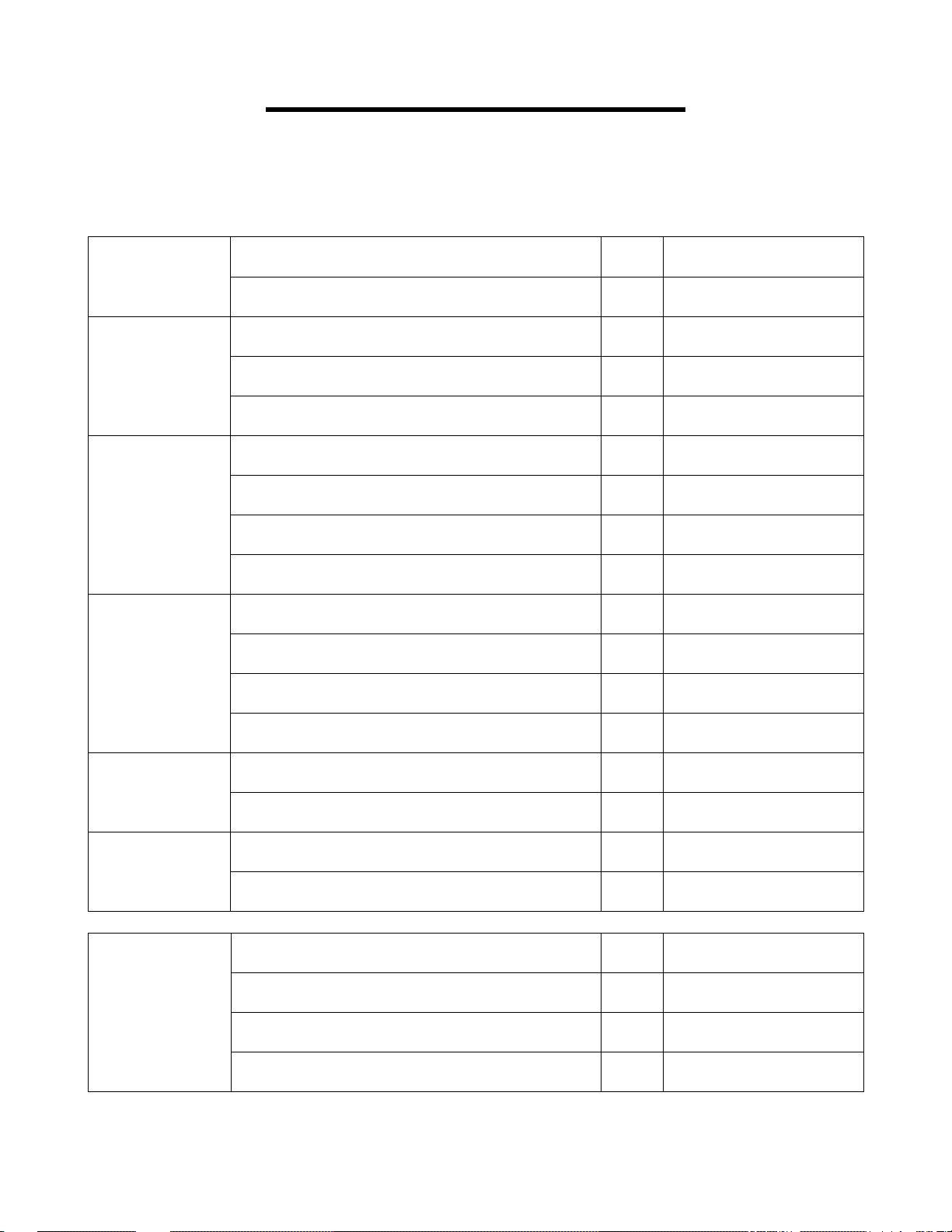
Indicator Settings
Start Setup End Setup
[[ [[
Buzzer
Buzzer Tone
Buzzer Duration
Buzzer Loudness
enable good read buzzer default
disable good read buzzer
single tone buzzer default
high-low buzzer
low-high buzzer
buzzer duration = 50ms default
buzzer duration = 100ms
buzzer duration = 200ms
buzzer duration = 400ms
buzzer loudness = maximum default
buzzer loudness = high
buzzer loudness = medium
X9
X1
X2
X3
X!
X8
X5
X6
X7
U1
U3
U!
Buzzer
Transmission
Startup Buzzer
Good Read LED
buzzer loudness = low
buzzer before transmission default
buzzer after transmission
enable startup buzzer default
disable startup buzzer
disable LED
LED duration = 0.2 seconds default
LED duration = 0.4 seconds
LED duration = 0.8 seconds
A-50
U5
WZ
W[
HD
HE
U5
U6
U7
U8
Page 57
Diagnostics
Start Setup End Setup
[[ [[
Diagnostic Codes:
Transmit software version
Transmit settings
Transmit only changes from default
Diagnostics
Transmit ASCII printable string
Transmit ASCII control string
Reset to default (RS-232)
Reset to default (USB-HID)
[2
[!
FBS
[B
ZW
V3
TV
A-51
Page 58

Appendix B
Resolving USB Installation Issues
The USB HID (Human Interface Device) keyboard driver is standard with Windows®. Most recent versions of
Windows include necessary files in the installed Windows system folders so driver installation is easy if not
automatic. It is possible for the user to cancel the HID driver installation before it is completed and this results in
a problem. Restarting Windows does NOT initiate a re-installation; the user must go into the device
management utility in Windows. Location and operation of the device management utility is different depending
on the version of Windows:
Windows® XP:
1. Go to the Start menu.
2. Select Control Panel.
3. Switch to Classic View if you are in Category View
4. Select System.
5. Select Hardware tab.
6. Select Device Manager
7. Double Click on Human Interface Devices
8. Locate the USB Human Interface Device with a ! in the icon.
9. Click on Update Driver
10. Follow instructions.
If XP fails to find the driver on the computer's hard disk, you may have to insert and point to the original
Windows XP CD-ROM to complete the installation. Also make sure you have rights to add new hardware to
your computer - some
XP installations problems can be solved by logging in as the Administrator of the computer.
11. Click Finish
Windows® 98SE & ME:
1. Go to the Start menu.
2. Go to Settings.
3. Select Control Panel.
4. Go to System.
5. Click on the Device Manager tab.
6. Double Click on the USB Human Interface Devices
7. Click on the Reinstall Driver button.
8. Follow directions.
If the installer cannot find the right driver file on your hard disk, you may have to insert the original Windows®
98SE or ME CDROM and point to it to complete the installation.
9. Click Finish.
Windows® 2000:
1. Log on as Administrator and open the Administrative Tools folder in your Control Panel.
2. Run the Computer Management utility.
3. Select the Tree tab on the left panel
4. Find the Device Manager entry under System Tools and click on it. The right panel will display current
devices.
5. Problem devices will be identified with an ! icon. Find either the HID Keyboard Device under Keyboards or
the USB Human Interface Device under Human Interface Devices and double-click on one of those entries.
6. Select the Driver tab at the top of the window and click on the Update Driver button. Follow the prompts to
re-install the HID driver.
B-1
Page 59

Windows 7 & Vista:
1. Go to the Start menu.
2. Select Control Panel.
3. Switch to Classic View if you are in Category View
4. Select System.
5. Select Hardware tab.
6. Select Device Manager
7. Double Click on Human Interface Devices
8. Locate the USB Human Interface Device with a ! in the icon.
9. Click on Update Driver
10. Follow instructions.
If Windows 7 or Vista fails to find the driver on the computer's hard disk, you may have to insert and point to the
original Windows 7 or Vista CD-ROM to complete the installation. Also make sure you have rights to add new
hardware to your computer - many Windows 7 or Vista installations problems can be solved by logging in as the
Administrator of the computer. In order to install new hardware in Windows 7 or Vista you may need to turn off
the UAC (UserAccount Control). UAC is turned off using the User Account icon. UAC is turned on using the
Sercurity Center icon.
B-2
 Loading...