

Worldwel LONGRUN 500LT3, longrun 350LA, longrun 500LA, longrun 600LA Operation Manual

INVERTER DC TIG ARC WELDER
LONGRUN 500LT3
OPERATION MANUAL
DO NOT INSTALL, OPERATE OR MAINTAIN THIS MACHINE WITHOUT READING
THIS MANUAL AND PLEASE ALWAYS THINK BEFORE YOU ACT.
WWW.WORLDWEL.COM
TECHNICAL SPECIFICATIONS■
- SUFFICIENT CAPACITY of main transformer by self-manufacturing
- ELECTRIC SHOCK PROTECTOR reduces No load voltage to 14VDC for user safety when welder is
not in use.
- Easy to verify welding current during welding by DIGITAL AMMETER.
- Optional REMOTE CONTROL BOX is available for adjusting output current without going back to
power source.
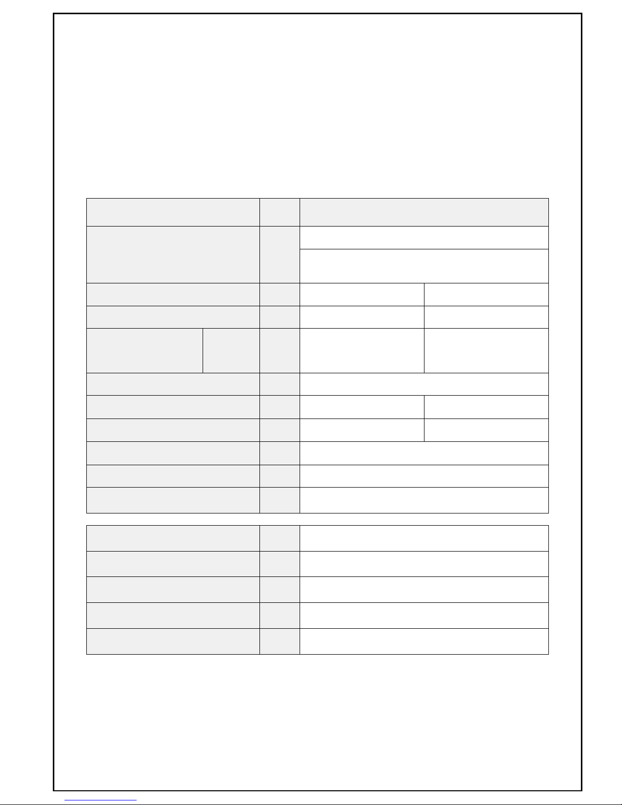
ITEM UNIT SPECIFICATION
Rated Input Voltage V
220/380/440, 50/60Hz
3 Phase
Process ― TIG STICK
Rated Output Current A 500 340
Input Current @ rated
output
380V A 21 15
No Load Voltage V 63 (380V)
Output Current Range A 15~500 20~340
Output Voltage @ rated output V 30 33.6
Duty Cycle @ rated output % 60
Dimension (W×D×H) mm 385 × 770 × 610
Weight kg 58
Crater Current Range A 15 ~ 500
Start Current Range A 15 ~ 500
Down slope Time Range sec 0.1 ~ 5
Gas After Flow sec 0.5 ~ 15
Cooling Method ― Air cooling / Water cooling

General Safe Practices
Wear approved safety glasses with side shields under your welding helmet or face shield and at all■
times in the work area.
When working above floor level, use a safety belt to protect yourself from a fall should you get a■
shock.
Do not install or place machine on or over combustible surfaces.■
Be sure that all installation, operation, maintenance and repair procedures are performed only by■
qualified persons.
Electric shock can kill.
Wear Dry, hole-free insulating gloves and body protection. Do not touch electrode with bare hand.■
Do not wear wet or damaged gloves.
Do not touch live electrical parts.■
Never dip the electrode in water for cooling.■
Properly install and ground all equipment.■
Protect yourself from electric shock by insulating yourself from work and ground. Use■
non-flammable, dry insulating material if possible, or use dry rubber mats, dry wood or plywood,
or other dry insulating material big enough to cover your full area of contact with the work or
ground, and watch for fire.
Turn off input power using the disconnect switch at the fuse box before working on the equipment.■
Frequently inspect input power cord for damage or bare wiring and repair or replace cord■
immediately if damaged.
Fumes and gases can be dangerous.
Welding may produce fumes and gases hazardous to health. Avoid breathing these fumes and■
gases. When welding, keep your head out of the fume. Use enough ventilation and/or exhaust at
the arc to keep fumes and gases away from the breathing zone.
Use enough forced ventilation or local exhaust (forced suction) at the arc to remove the fumes■
from your breathing area.
Use a ventilating fan to remove the fumes from the breathing zone and welding area.■
Arc rays can burn eyes and skin.
Use welding helmet with correct shade of filter to protect your eyes from sparks and the rays of the■
arc.
Wear welders cap and safety glasses with side shields. Use ear protection when welding out of■
position or in confined spaces. Button shirt collar.
Wear complete body protection. Wear oil-free protective clothing such as leather gloves, heavy■
shirt, cuffless pants and high boots.
Welding sparks can cause fire or explosion.
Remove fire hazards from the welding area. If this is not possible, cover them to prevent the■
welding sparks from starting a fire. Remember that welding sparks and hot materials from welding
can easily go through small cracks and opening to adjacent areas. Avoid welding near hydraulic
lines.
When not welding, make certain no part of the electrode circuit is touching the work or ground.■

Accidental contact can cause overheating and create a fire hazard.
Do not weld on drums, tanks, or any closed containers unless a qualified person has tested it and■
declared it or prepared it to be safe.
Connect the work cable to the work as close to the welding area as practical. Work cables■
connected to the building framework or other locations away from the welding area increase the
possibility of the welding current passing through lifting chains, crane cables or other alternate
circuits. This can create fire hazards or overheat lifting chains or cables until they fail.
INSTALLATION■
The welding machine shall be installed at a place ;●
free from the inflammables․
less humidity, dirt and dust․
protecting from influence of direct sunlight, wind and rain․
not generated oil vapor and corrosive gas․
operating temperature range is from -10 to 40℃ ℃․
least 30 away from wall and other welding machine㎝․
Input Connection (Rear of the machine)●
Be sure the voltage, phase and frequency of the input power is as specified on the name plate
located on the rear panel of the machine.
To connect the power cables, turn the power switch OFF․
Verify the voltage to be supplied from main power.․
Open the cover of terminal plate and connect the power cable to the power input terminal on the rear․
of the machine and close the cover of terminal plate.
If the input power is single phase, connect two cables on left and right terminal without center.√
For grounding the machine, connect a ground wire to the ground terminal marked with the symbol is․
located on the rear panel of the machine.
Connect the gas hose to the gas input terminal.․
If you want to connect the water cooling unit, connect the water hose to WATER IN terminal.․

Input voltage selection※
220V 380V 440V
Output Connection (Front of the machine)●
Connect the work cable (which is connected to the work clamp) to the METAL terminal.․
To connect the TIG torch, connect a electrode cable to the TORCH terminal and a torch switch․
connector to the torch switch receptacle and a gas connector to the output gas receptacle.
If you want to connect the remote controller, connect the connector of remote controller to REMOTE․
CONTROL terminal.
If the water cooling unit is installed, connect the water input hose of water cooled torch to WATER OUT․
terminal of welder.
AIR COOLING WATER COOLING
․ Verify the connection of voltage selection terminal.
If necessary to change it,√
Remove the cover of input voltage selection plate.․
Position the wires for the voltage to be supplied from main power.․
For 380V and 440V input, position a switch for the voltage would be used which is rear.․
 Loading...