

Page 1

WORLDTRACKER
GLOBAL ASSET TRACKER
Title: WTGAT Tracker Manual
Doc Type: Application note
Doc ID: WTGAT
Revision Index Date Name Status/comments
16-4-2009 WTGAT Manual
We reserve all rights to this document and the information contained therein. Reproduction, use or
disclosure to third parties without express permission is strictly prohibited.
Performance characteristics shown in this document are estimates only and do not constitute a warranty or
guarantee of product performance. TRACKINGTHEWORLD does not support any applications in connection
with weapon systems. Since TRACKINGTHEWORLD products are not designed for use in life-support and
commercial aviation applications they shall not be used in such products. In devices or systems whereby
malfunction of these products can be expected to result in personal injury and casualties,
TRACKINGTHEWORLD customers using or selling these products do so at their own risk and agree to keep
TRACKINGTHEWORLD harmless from any consequences. TRACKINGTHEWORLD reserves the right to
make changes to this product, including its circuits and software, in order to improve its design and/or
performance, without prior notice.
TRACKINGTHEWORLD makes no warranties, neither expressed nor implied, regarding the information and
specifications contained in this document. TRACKINGTHEWORLD assumes no responsibility for any claims
or damages arising from information contained in this document, or from the use of products and services
detailed therein. This includes, but is not limited to, claims or damages based on the infringement of patents,
copyrights, mask work and/or other intellectual property rights.
Contact
For further info, please contact us:
TRACKINGTHEWORLD, Inc.
1633 Bayshore Hwy. Suite 390
Burlingame, CA 94010
Tel: 1-650-692-8100
Fax: 1-650-692-8022
www.trackingtheworld.com
e-mail: [email protected]
Page 2

- 2 -
Personal Tracker (WTGAT) V1.15 Manual
Index
1. Basic first startup and testing Page 3-8
Important before you start
Check before starting
2. Getting started, use Hyper Terminal to test
WTGAT
3. Configuration and setup Page 14-26
4. SMS commands accepted by the tracking unit Page 27-32
Unit activation and sleep Mode
Software and hardware lock-ups
5. Uploading the Operating System to the WTGAT Page 33-35
6. Messages send by WTGAT Page 36-43
7. Serial port data sending using the GSM Modem Page 44
8. Priority of Messages Page 44
9. a. Basic testing and problem solving flow chart Page 45
b. Motion Alert flow chart Page 46
c. Park Alert flow chart Page 47
10. GPRS testing Page 48
11. AT COMMANDS for GPRS support Page 49-64
12. Receiving and sending GPRS data Page 65
13. WTGAT Connections Page 66-70
14. Technical Specification Page 71-74
15. Federal Communications Commission (FCC)
Statement
Page 4-5
Page 6-8
Page 9-13
Page 32
Page 32
Page 75
2
Page 3
- 3 -
1.Basic first startup and testing
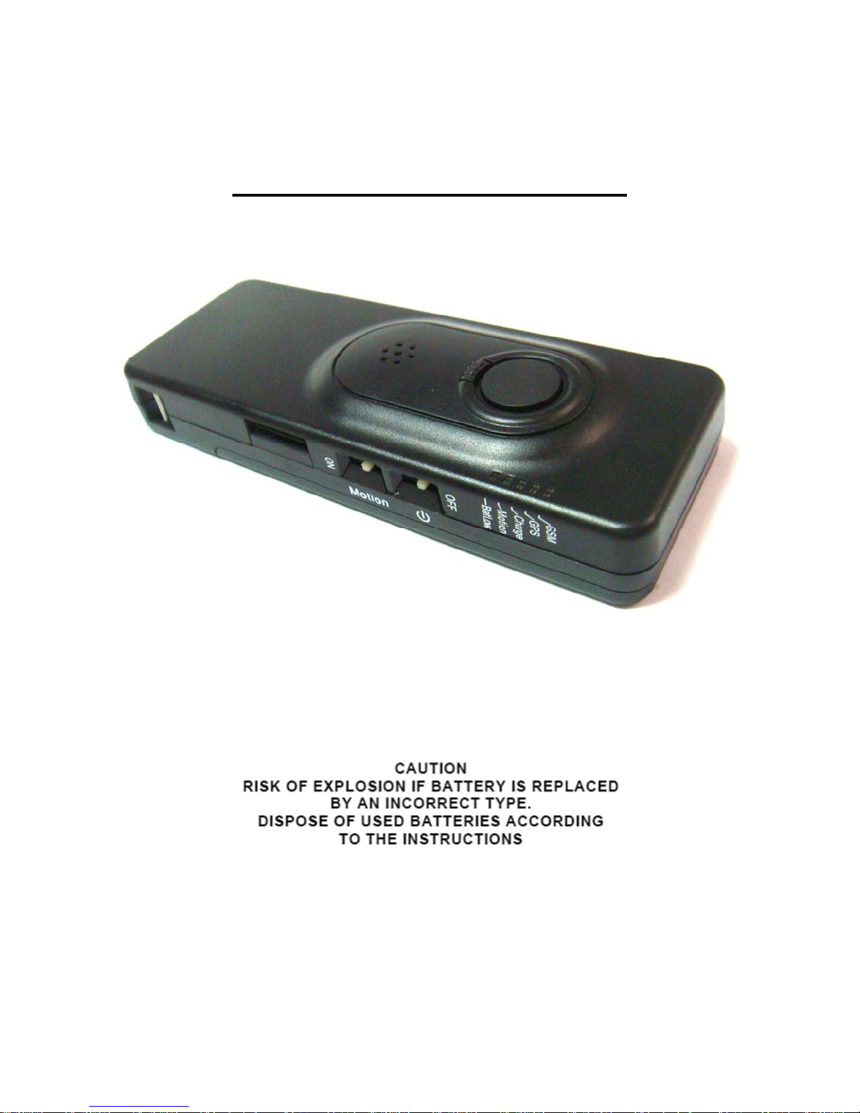
The WTGAT has been designed to make installation, testing and configuration simple. Please note that you
can only use the special serial cable supplied for USB communication.
3
Page 4

- 4 -
Important before you start:
** PLEASE MAKE SURE YOU ALWAYS USE THE SAME CONFIGURATION MENU PROGRAM THAT
IS INCLUDED WITH ANY NEW OR UPDATED FIRMWARE. WHEN NEW OPTIONS ARE ADDED YOU
MUST USE THE NEW OR UPDATED CONFIGURATION MENU SOFTWARE.
The power switch is specifically designed to be difficult to switch on/off. Once the unit is on, please
always keep it on. MAKE SURE THE POWER IS OFF WHEN INSTALLING THE SIM CARD!
The SIM card being used in the unit should have the default PIN numbers, “0000”, or have no PIN
numbers.
While connecting a charger cable to the unit, the red charger LED will be on if battery is charging. The
charger LED will turn off once the battery is fully charged. Please use external battery charger (wall
charger) for optimal charging time.
It is possible to charge using USB port on computer system, but charging time will be a lot
longer or battery may not be able to charge to maximum as power output from the USB port is
limited.
When the battery is low the red battery low LED will be on.
When you start the "GPS tracking configuration WTGAT" program, there is an upload configuration
button on the main menu. You need to click on it to upload the original configuration from WTGAT
before you start. Then, please simply change the fields that need to be changed.
Please make sure that all the blanks in the configuration window are filled in, apart from SMSC, base
phone no. 2/3, dial- up phone no. and New Password parts.
The SMSC number in the configuration window is the phone no. of the Short Message Centre (GSM
provider). It is usually pre-set in the SIM card. If you are not sure about it, please leave it blank.
APN (Access Point Name) and G PRS login name & password are c ase sensitive. Please check with
your GSM provider first.
Port Settings (in Hyper Terminal)
1. Bits per second: 9600
2. Data bits: 8
3. Parity: None
4. Stop bits: 1
5. Flow control: None
While downloading system firmware to the unit with Hyper Terminal, please set to “Xmodem.”
4
Page 5

- 5 -
On a windows based computer you will be able to use ‘Hyperterminal’ (free with Windows). For PDA or
Pocket PC you can use several communication programs that can be downloaded from the internet like
‘ZTERM for Pocket PC’ (http://www.coolstf.com/ztermppc).
When you receive the unit, we recommend configuring the unit functions and setup using the Personal setup
configuration program. The WTGAT has many functions that will allow the unit to operate for different user
applications including security and continues tracking using SMS or GPRS.
VERY IMPORTANT:
Before you can start using the WTGAT the battery will need to be charged. The battery can be charged with
the unit powered on or off. The power on switch is located on the side off the unit.
Disconnect external battery charge or communication cable first before powering down the unit.
The build in battery charger automatic charges the battery whenever you connect to the battery ch arger.
When you power on the unit 3 leds will flash for about 1-2 seconds.
At startup the WTGAT will test memory, GPS module, GSM module and if sim card is installed.
The WTGAT cannot operate without s im car d in s t a l le d .
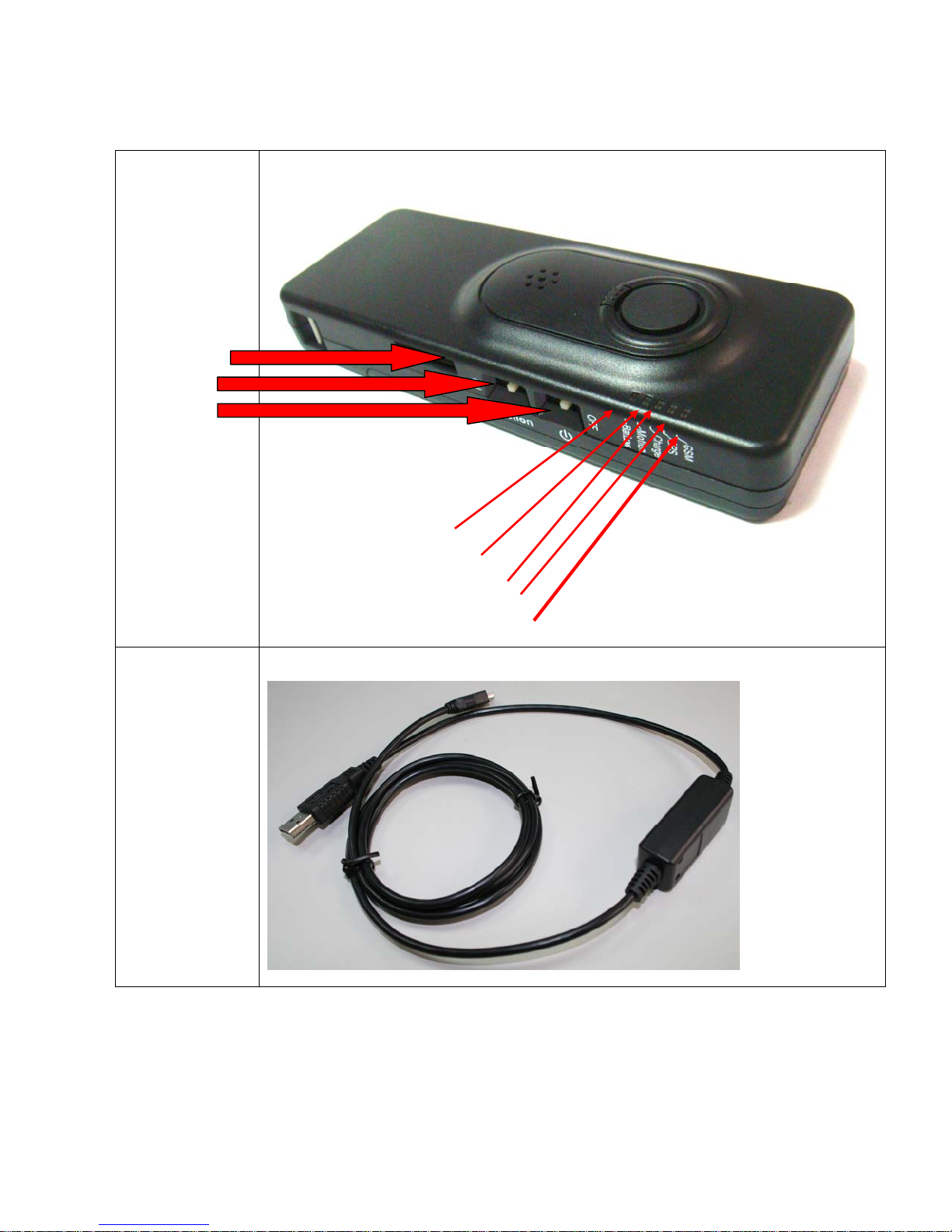
The 5 leds on the WTGAT have the following functions:
Yellow led
This is the GSM status led.
The LED will be OFF when there is NO GSM signal.
The LED will be ON if the GSM module OK and has GSM signal or is in sleep mode (except deep sleep
mode).
If blinking the GSM module is in test mode.
During diagnostic startup the GSM led will flash.
Green led
This is the GPS status led.
If off the GPS module is powered down.
If on then the GPS module has power, but non-valid GPS location.
If blinking the GPS module has power and valid GPS location.
Red led1
This is the Battery status led.
If off and charger is connected then battery is fully charged.
If on then battery is charging.
Blue led
This is the Park, Motion or status LED when Panic input is configured to pickup and hang up Voice call (Park
or Motion function can be configured using the configuration menu program).
If off the Park, Motion or 24H no movement detection is off.
If ON then Park, Motion or 24H no movement detection is on.
If flashing then Voice call active or Panic input activated.
Red led2
This is the low Battery status led.
If off then battery power OK.
If on then battery power is low.
5
Page 6
- 6 -
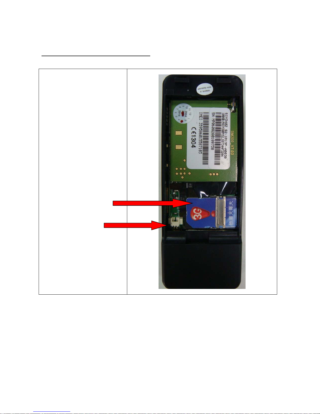
Sim card and battery Installation (BACK VIEW)
MAKE SURE THE POWER IS OFF WHEN INSTALLING THE SIM CARD!
Remove the back part from the
WTGAT to insert SIM card and
Battery.
SIM CARD
BATTERY
(*)
Please Note : ONLY USE THE SUPPLIED BATTERY WITH THE UNIT
For the first time when you install a new sim card the pin
number (if configured) must be set to “0000” or disabled.
MAKE SURE THE PIN NUMBER IS CORRECT BEFORE
INSTALLING SIM CARD. READ SETUP SIM PIN CODE
INSTRUCTIONS FIRST!
6
Page 7
- 7 -
Multi I/O port
Motion Switch
Power On/Off
Switch
SIDE VIEW
Low Battery Led
Park/ Motion / Panic led
Battery Status Led
GPS Status Led
GSM Status Led
USB/Serial/Charger
Cable connection
(ONLY USE THE
CABLE SUPPLIED
WITH THE UNIT)
* It takes about 1 Minute or less for the WTGAT to startup (If
battery voltage is very low it may take several minutes).
7
Page 8
- 8 -
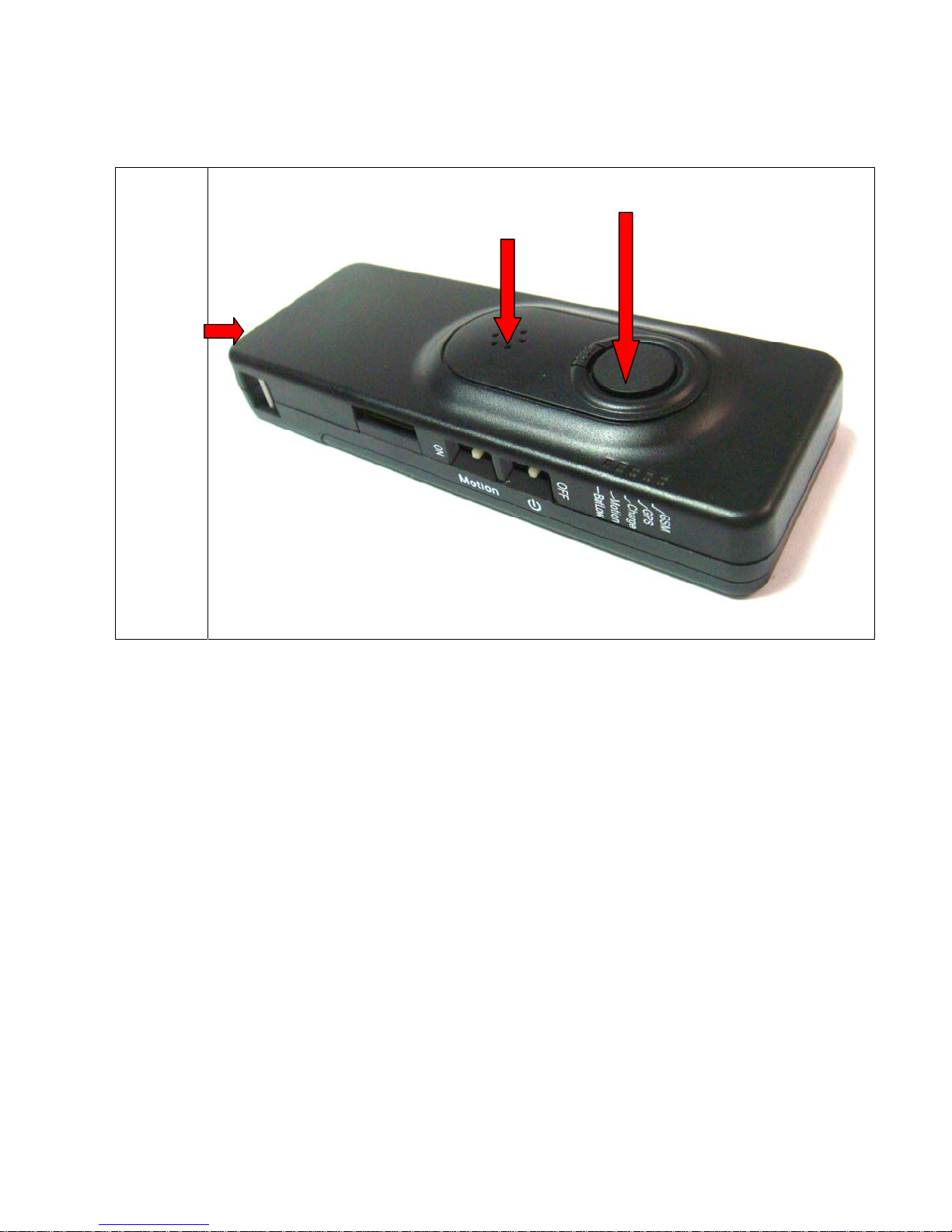
WTGAT
Front View
Microphone
PANIC BUTTON
SPEAKER
8
Page 9

- 9 -
2. Getting started, use Hyper Terminal to test WTGAT
Step 1
Connect WTGAT with your PC using the USB port. You may need to install the USB driver
that is supplied with the unit. This driver will install a USB serial port on your computer.
Step 2
Using Hyper Terminal
The PC will need to be running HYPERTERMINAL, which is a free program that
comes with Windows.
If HyperTerminal is not currently installed on the PC you will need to do the
following:
1. Go to Start/Settings/Control Panel.
2. Go to Add/Remove Programs/Windows Setup Tab. This will bring up a list of
components that can be installed.
3. Put a tick in the Communications Check box and double click. This will bring up a
list of components that can be installed. Put a tick in the box next to HyperTerminal.
You may need to insert your Windows Disk to install the program.
4. You may need to restart your computer after the program has installed.
5. Remember to connect the serial port on the unit to the serial port on the PC.
Once HyperTerminal is installed and running you will need to set the Baud Rate to
9600 Baud and set the Com Port (usually Com 4 on a laptop) to the USB serial port
created.
We strongly recommend that the unit be tested using a computer as this allows all
options to be tested quickly and easily. The operating system/or a new or modified
operating system can only be uploaded (in x-modem format) if the unit is
connected to a serial port on a computer.
Step 3
Power up the unit. The Yellow, Green and Blue led will flash for 1-2 seconds.
Please make sure you have charged the battery and sim card is installed.
9
Page 10

- 10 -
Startup Personal Tracker WTGAT
Testing Memory
-PASS
Operating System Checksum
-PASS
Testing Real Time Clock
-PASS
Current Time: 00:00:02
Current Date: 01-01-00
Testing GPS module
Non valid GPS location
Testing GSM module
-PASS
Testing Sim Card present
-PASS
Press M to enter Diagnostic menu
(If M is not pressed within 5 seconds the WTGAT will start normal running mode)
Step 4
Get into Diagnostic Menu
Pressing the M key will then take you to the Diagnostic Main Menu.
The following are the options in the Diagnostic Main Menu:
DIAGNOSTICS MAIN MENU :
Current Operating System :Personal Tracker WTGAT 18-07-2007
Press 0 to upload operating system (X-MODEM format)
Press 1 to test GSM module and Sim card
Press 2 to read GSM signal strength
Press 3 to test GPS module and GPS location
Press 4 to read Battery voltage level
Press 5 to Read Input Signals
Press 6 to output GPS sentences to serial port
Press 7 to Display/Enter time and date
Press 8 to direct connect to GSM modem
Press 9 to test Vibration sensor and Buzzer
(Press M to Return to MAIN MENU)
Press Q to Quit
Test 1 Test GSM module and SIM card on board
This will test if the tracking unit can communicate with the GSM modem and that a SIM
card is installed. The tracking unit will not work if there is no SIM card installed.
After testing you will return to the Diagnostic Main Menu.
Test 2 Test GSM signal strength
10
Page 11

- 11 -
The signal strength will be shown in HyperTerminal as:
Low
Medium or
High
Test 3 Test GPS module an d GPS locati on
The following will appear on screen in Hyp erT erminal:
Testing GPS module
Non-valid GPS location
Press M to Return to MAIN MENU
Non-valid GPS location
Press M to Return to MAIN MENU
Non-valid GPS location
The GPS location will always be either:
Valid or
Non-valid
It may take several minutes for the GPS receiver to find the satellites and
return a valid location. Remember the GPS will only find a satellite if the
WTGAT is outside and the signal is blocked by metal (unit must face open sky).
Test 4 Read battery voltage level.
Press M to Return to MAIN MENU
Current battery level:80%
Test 5 to Read input signals
Current input signals
Panic button
- NOT Activated
Park Switch
- NOT Activated
AUX1 Digital
- NOT Activated
AUX2 Analo g
- NOT Activated
Press M to Return to MAIN MENU
Test 6 Test output GPS sentences to serial port
The GPS sentences are directly sent from the unit to the serial port.
Press M to return to main menu.
$GPGSA,A,3,01,05,14,22,25,11,20,30,,,,,2.1,1.2,1.7*33
$GPGSV,3,1,10,25,60,317,42,01,58,224,41,14,53,136,45,22,40,053,45*70
$GPGSV,3,2,10,30,28,104,44,11,24,251,42,05,16,129,45,20,10,226,38*74
$GPGSV,3,3,10,18,03,050,18,47,46,005,40*7E
$GPRMC,213113.000,A,4100.7769,S,17053.1331,E,0.05,49.11,230206,,*2F
$GPGGA,213114.000,4100.7769,S,17053.1331,E,2,08,1.2,44.6,M,25.8,M,0.8,0000*5D
$GPGSA,A,3,01,05,14,22,25,11,20,30,,,,,2.1,1.2,1.7*33
$GPGSV,3,1,10,25,60,317,42,01,58,224,41,14,53,136,45,22,40,053,45*70
$GPGSV,3,2,10,30,28,104,44,11,24,251,42,05,16,129,45,20,10,226,38*74
11
Page 12

- 12 -
$GPGSV,3,3,10,18,03,050,15,47,46,005,40*73
$GPRMC,213114.000,A,4100.7769,S,17053.1331,E,0.06,40.44,230206,,*22
$GPGGA,213115.000,4100.7769,S,17053.1331,E,2,08,1.2,44.6,M,25.8,M,0.8,0000*5C
(If no key is pressed the GPS sentences will stop after 1 minute and return to main
menu).
Test 7 to Di splay/Ente r ti m e and date
Current Time: 11:07:55
Current Date: 08-08-07
Press 0 to change Time
Press 1 to change Date
Press M to Return to MAIN MENU
The WTGAT has internal time clock and battery backup. An internal battery backup
will keep this time running for up to 5-10 years. Please configure your current time
and date for the first time when you receive the WTGAT. The Time and Date will not
be lost if power or battery is removed!
Test 8 direct connect to GSM modem
This test will allow you to test communication using AT commands between your co mputer
and the GSM modem.
The AT command ‘AT comstop’ <enter> or if no command has been send to the modem
for more then 60 seconds the direct modem connection test will end.
For GPRS we recommend you do manual test first to test if your GPRS setup is correct.
(See GPRS section for information about the GPRS Testing).
Press Q to exit!!
By pressing Q you will exit the Diagnostic Main Menu and return the unit to
normal operation. If you do not press Q or any other option within 2 minutes the
unit will return to normal operation.
The unit will display the GSM Modem information, IMEI number and GPS info
directly after you Quit the Diagnostic Main Menu.
To return from normal operation to the Diagnostic Main Menu press X (or x).
Keep pressing X until the Diagnostic Main Menu appears. Please note that this
make take several seconds or more if the WTGAT is sending or receiving data!
Please always press “Q” after finish tests to exit diagnostic menu.
Modem information:
When you quit the 'DIAGNOSTICS MAIN MENU:' the tracking unit will report information about your GSM
modem:
Sample:
Modem Info:
ATI
SIMCOM_Ltd
SIMCOM_SIM300
12
Page 13

- 13 -
Revision:1008B09SIM300M32_SPANSION
OK
IMEI:
AT+GSN
351525018440223
OK
GPS Info:
$GPTXT,01,01,02,u-blox ag - www.u-blox.com*50
$GPTXT,01,01,02,ANTARIS ATR062x HW 80040001*26
$GPTXT,01,01,02,ROM CORE 5.00 Jan 09 2006 12:00:00*76
$GPTXT,01,01,02,LIC 1EBF-BD07-E83D-6BE1-0F7A*50
$GPRMC,,V,,,,,,,,,,N*53
$GPVTG,,,,,,,,,N*30
connect
Please Note:
During normal running mode the WTGAT will output GSM modem communication.
When the WTGAT is in normal operating mode the WTGAT requires the four-digit
password code (can be configured in the GPS Tracking configuration menu. Default is
‘1234') to return to Diagnostic mode after it receives the 'X' or 'x' command from
the serial port.
The password must be entered after the tracking unit sends the 'OK0' or 'OK1' command.
The correct password must be followed by <CR> (ENTER) to confirm password entered.
You must enter the correct password within 8 seconds or the tracking unit will return to
normal operating mode.
13
Page 14
- 14 -
3. Configuration and setup :
When the tracking unit powers up it will enter the ‘Diagnostic menu’ first. If no key is pressed for 5 seconds
the unit will enter normal operating mode.
Only change the settings that you require different, leave all other settings the same.
Please note : The ‘WTGAT-setup.exe’ program can only access the
tracking unit if the unit is working in normal operating mode !!!! So
after Power ON you must wait +/- 1 minute or wait until the Yellow
(GSM status LED) is flashing.
After power up you must wait until the unit passes the Diagnostic test. In Diagnostic test mode you cannot
connect to the tracking unit and you must wait at least 1+ Minutes before connecting.
In normal running mode (after diagnostic mode) the tracking unit may also be busy in other processes and
the unit will only response to the configuration software after finishing the process.
Therefore, when upload or download configuration, it may need to wait for few minutes especially the unit
was setup for real time tracking already.
The best timing to upload the configuration is right after quit from diagnostic menu with hyper terminal."
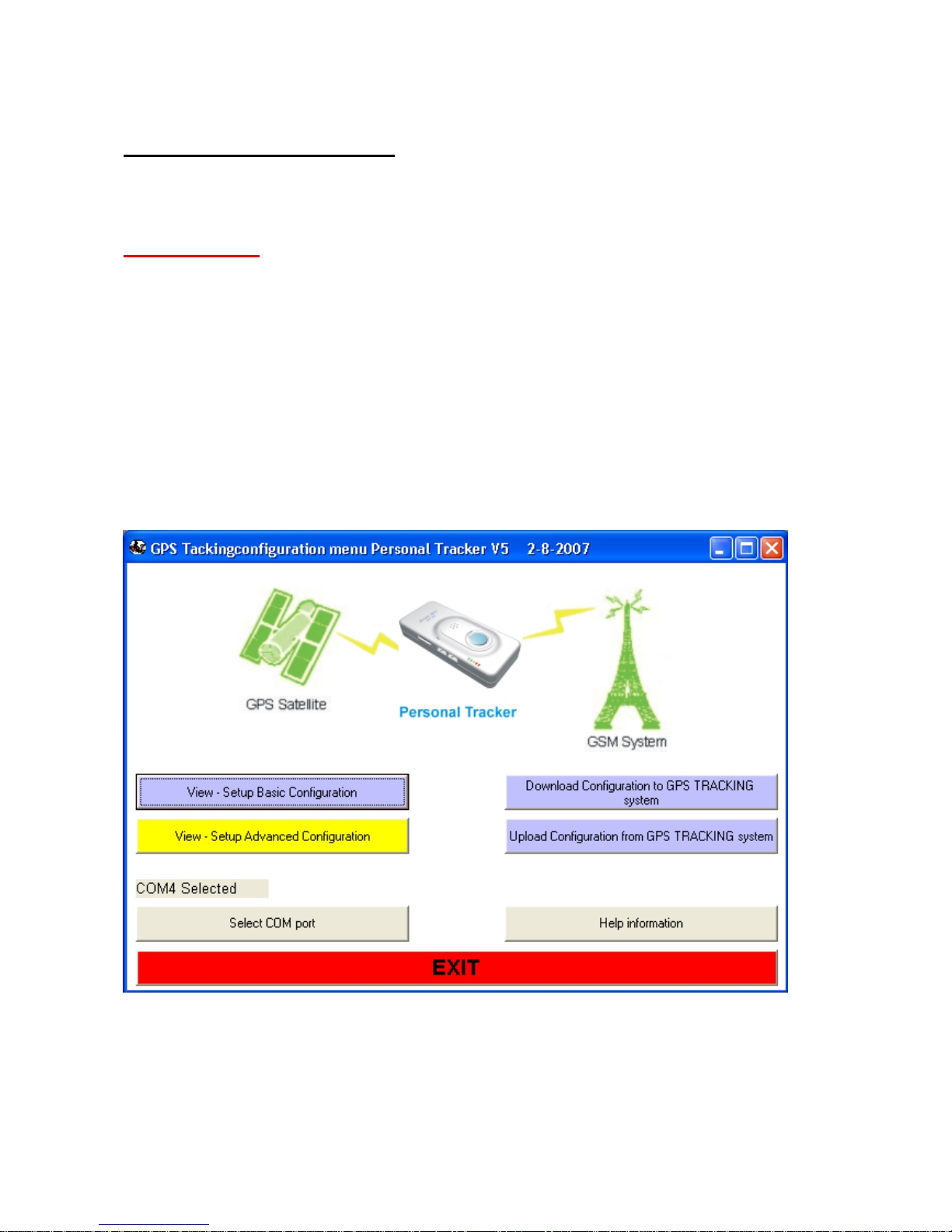
Start up the file WTGAT-setup.exe file
14
Page 15
- 15 -
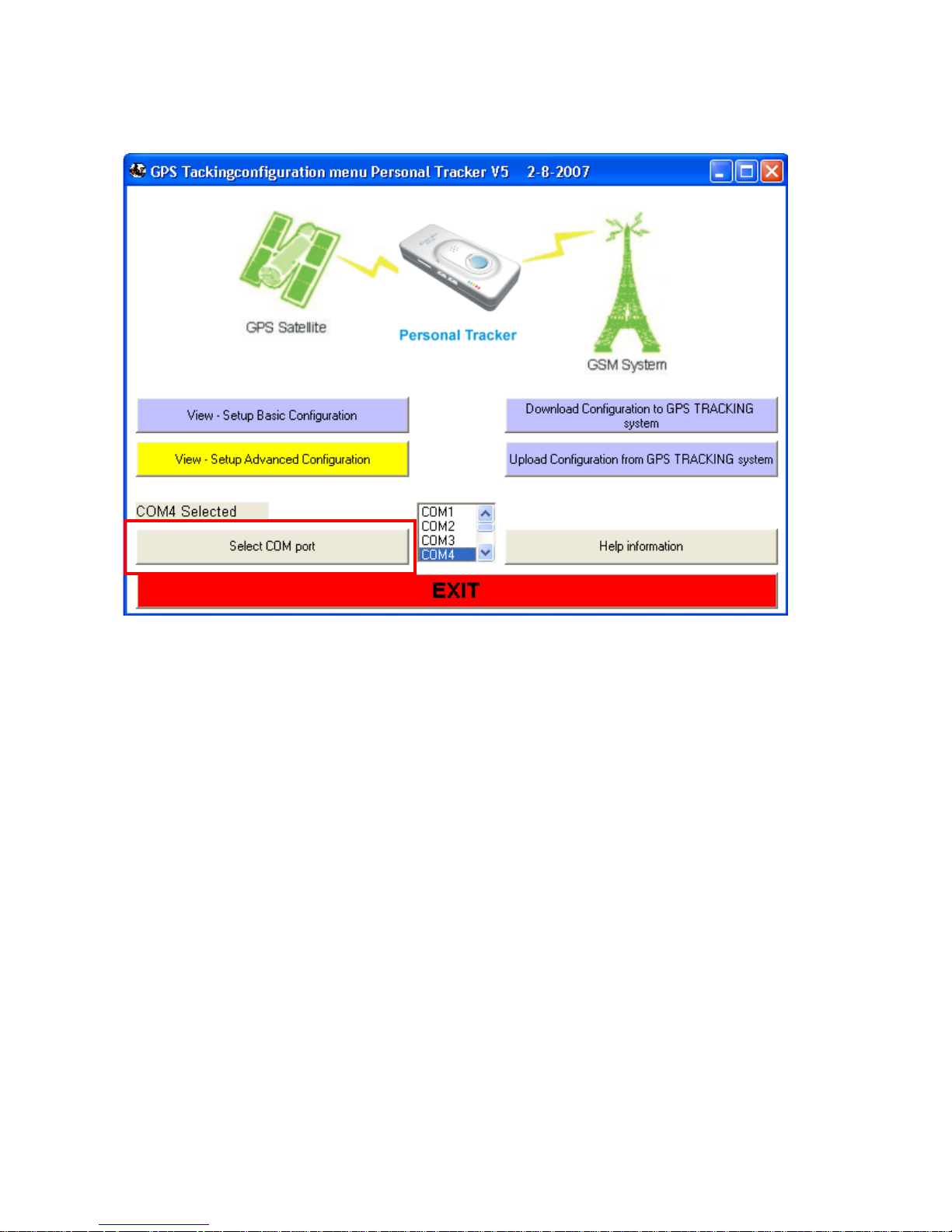
Select Com port
15
Page 16
- 16 -
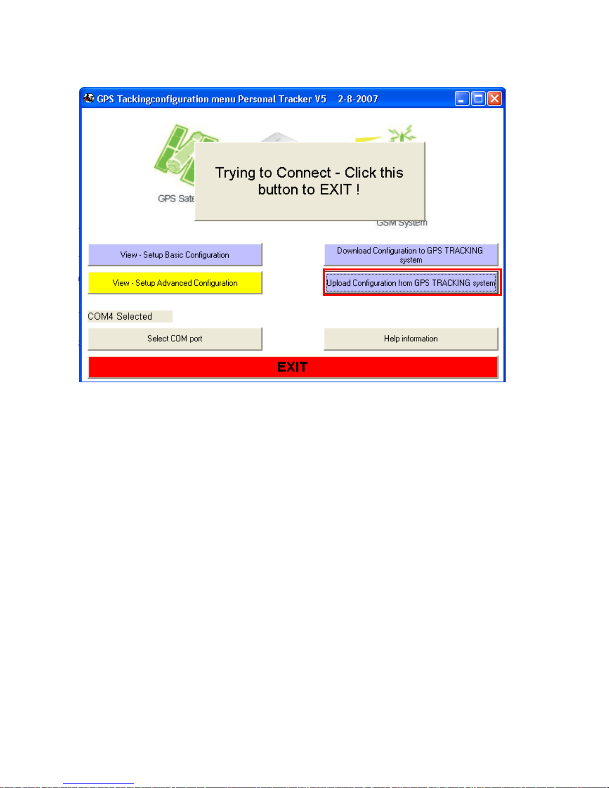
Upload configuration from WTGAT
Always upload the current configuration from the WTGAT first. This way it is easy to configure and the setup
the unit. You must use the correct WTGAT firmware version. The configuration file cannot be uploaded if the
version is incorrect.
16
Page 17
- 17 -
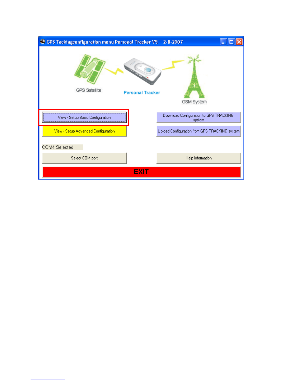
After upload select View –Setup Basic Configuration
17
Page 18
- 18 -
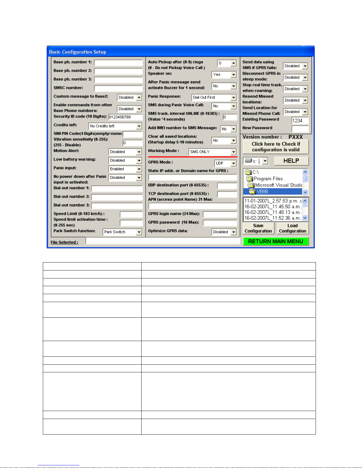
Basic configuration
Overview (ONLY CHANGE OPTIONS THAT NEED TO BE DIFFERENT)
Settings Description
Base phone number 1: Setup the control center base 1 station number (*)
Base phone number 2: Setup base 2 phone number (*)
Base phone number 3: Setup base 3 phone number (*)
SMSC number: Setup SMSC number if required
Custom message to Base
Option can be enabled or disabled (2)
Phone number 2:
Enable com m ands from other
Base Phone numbers
Option to receive messages from other base stations (if
enabled).
By default the option is enabled. (*)
Security ID code Security ID code to receive messages from other base
stations.
Credits left: Disable or enable all out going messages
SIM PIN Code: SIM Pin access code. Default is: 0000 (4)
Vibration sensitivity Adjust the sensitivity of motion sensor (lower value will be
more sensitive). Enter zero(0) and the WTGAT will never
enter sleep mode. Enter 255 and the WTGAT vibration
detection is disabled. The WTGAT will not wake up if
vibration is detected.
Motion Alert: Enable or disable motion alert (6)
Low battery warning: Enable or disable to receive message when battery power
low. Battery power left cannot be checked when the
18
Page 19

- 19 -
V
A
A
WTGAT is in sleep mode.
Panic input: Disable or enable panic button input (5)
Panic Response Select to dial-out first or send SMS first when Panic Input
is activated.
SMS during Panic Voice Call: Receive SMS location message(s) during Panic Voice
call. This will send every 10 seconds 1 SMS message as
long as the Voice call is connected. Only 1 SMS is send if
GPS location is NON-Valid and up to 3 messages when
GPS location is valid. Please note that not all GSM
providers allow sending SMS when connected to
oice call. Please check with your GSM provider first.
Dial-out number 1: When entered this number will be dialed automatic when
panic button is activated. (3)
Dial-out number 2: When entered this number will be dialed automatic when
panic button is activated. (3)
Dial-out number 3: When entered this number will be dialed automatic when
panic button is activated. (3)
Speed limit: Over the speed limit will send out message (1)
Speed limit activation time: Time of the speed keep over speed limit (1)
Park/Moti on/24H Swit c h
Function:
Select function for Park, Motion or 24H switch.
The selected function will be enabled when the switch is
ON.
Auto Pickup after (0-9) rings Setup if the unit will auto pickup incoming voice call
‘0’ zero will not enable any incoming voice calls
Speaker on Select if build in Speaker will be activated for incoming
phone call.
After Panic message send
activate Buzzer for 1 second
Select to activate the internal buzzer for 1 second when
Panic button is activated and SMS message sending was
successful.
Panic Response: Select ‘Dial out’ or send SMS/GPRS message first.
SMS tracking interval online For SMS or GRRS mode and WTGAT is activating.
Add IMEI number to SMS
messages
The GSM IMEI number can be added to every SMS
message received except multiple location messages.
The IMEI number is added at t h e end off the mess a g e .
Clear all saved locations: This will clear all saved GPS locations from memory
Working mode Switch between SMS only mode and SMS+GPRS mode
------------------------------------------- -----------------------------------------------------------------------------
GPRS Mode: Select between UDP or TCP protocol
Static IP Addr. Or Domain name
for GPRS:
Enter static IP address or Domain name to receive GPRS
data
UDP destination port UDP port for GPRS data
TCP destination port TCP port for GPRS data
PN name
ccess point name for GPRS data) (case sensitive)
GPRS login name For setup GPRS connection
GPRS password For setup GPRS connection
Optimize GPRS data
The ‘location message’ when using GPRS will be reduced
by about 25% to save data communication costs. Remove
comma, points and other exclamation from GPRS data.
Send data using SMS if GPRS
fails
This will send the data as SMS message if the GPRS
connection fails or is not available. As soon as GPRS is
available again the tracking unit will continue sending data
19
Page 20

- 20 -
using GPRS (for real time tracking only).
Disconnect GPRS when in sleep
mode
Stop real time tracking when
roaming
When the unit enters sleep mode it will disconnect from
GPRS
When the unit enters a roaming area it stop sending Real
time tracking locations (they are saved to memory –
‘Resend Missed locations is enabled’). When the unit
returns to non- roaming area the real time tracking will
restart (missed messages will be send back).
Resend Missed locations When enabled any activation or ‘Real time tracking’
messages will be automatic resend.
Send Location for Missed Phone
Call
The current or last know location can also be requested
from the WTGAT after missed Phone call (the call is not
picked up by the WTGAT). If the WTGAT picks up the call
no location message is returned. Only for missed calls (#)
Existing password To connect to unit via com port
New password To change the password
Check configuration is valid Check if the setting is valid (This check can only check
basic setup errors)
Select directory Select the directory of setting saved file
Select file Select the setting saved file to load
Load configuration Load the setting from computer file
Save configuration Save the settings into computer file
File selected The selected file will show in this window
Return to main menu Return to main menu
(1) If activated the unit will try to send SMS or GPRS message (depending on settings)
back to base with the current speed and location. The speed displayed in the
message may not be the activation speed, but whenever the option is activated the
speed was more then the speed limit configured for the set time.
(2) Base Phone number 2 must be configured.
(3) There are 3 dial-out numbers that can be configured when the Panic button is
activated. The WTGAT will start dialing from the first number. If no connection can
be made within 30 second the next number will be dialed. The WTGAT will continue
to try all three numbers (if configured) for up to 3 times. If any
number connects then no more other numbers will be dialed.
(4) Make sure that the pin code is correct configured for your sim card. If the pin code is
incorrect the sim card may get ‘blocked’.
(5) The Panic status LED (BLUE LED) will be ON once the WTGAT detects that you have
pressed the Panic input button. To activate the Panic input the user must press the
panic input until the Blue LED is ON.
(6) If MOTION alert is enabled you must move (vibration) the WTGAT at least one time
every 1 minute. If no movement or vibration is detected the internal buzzer will beep
for 30 seconds. You must then move the WTGAT within the 30 seconds.
If not the WTGAT will send ‘Motion alert activated’ and or location message. Once
Motion alert has been activated it will automatically deactivate.
(#) You must configure the ‘Auto Pickup after (0-9) rings’ for a value 3 or more. As
soon as you hear the first ring tone you must hang up. If not no message will be
returned. (May not work with all GSM providers or SIM cards)
Important (*):
Base Phone number 1 must be different then Base Phone number 2 and Base
Phone number 3. So all Base phone numbers must be different from each other.
20
Page 21
- 21 -
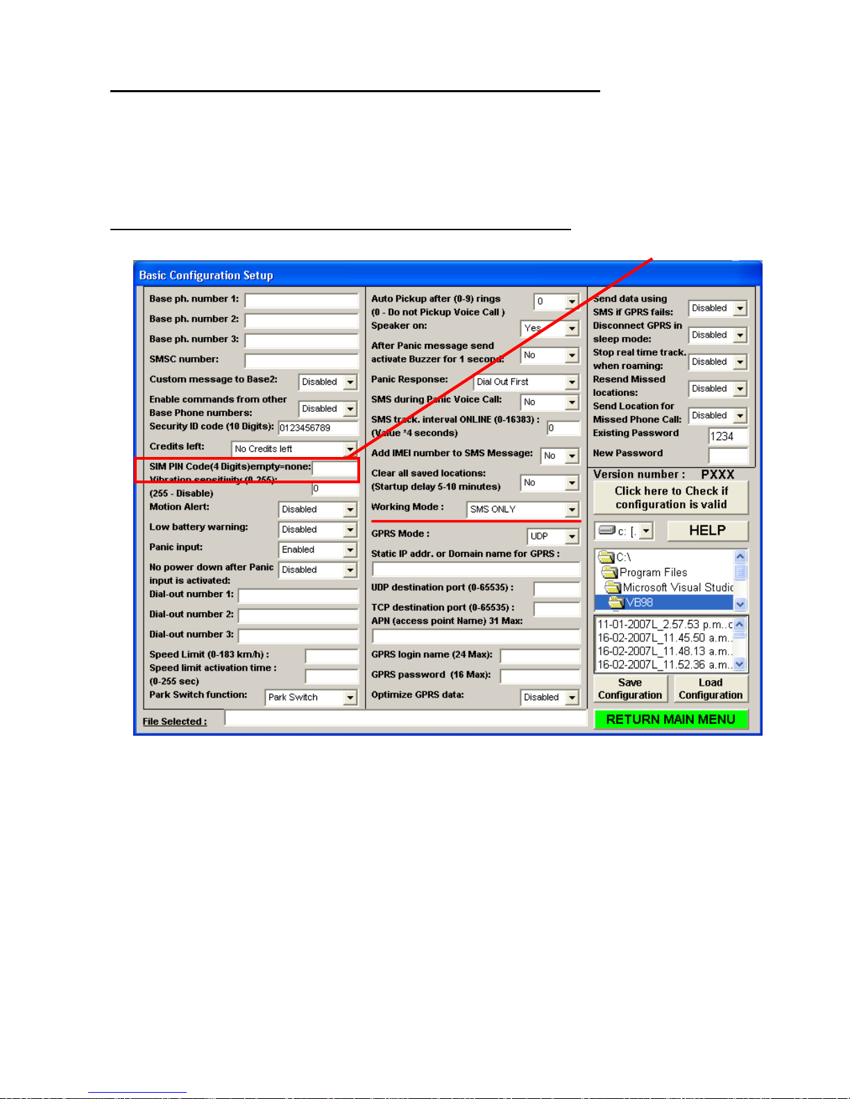
Installing SIM card with different PIN NUMBER then 0000 or None:
The default configuration after operating system upload or when you receive the WTGAT for the first time is
NO SIM PIN number or SIM PIN number is 0000 (4 * zero). If you cannot remove SIM PIN number make
sure that your SIM PIN is configured for 0000.
The WTGAT will first test if SIM PIN number is required. If the SIM card requires PIN number then the
WTGAT will try to access the SIM card using the default pin number 0000 (4* zero).
To change the SIM PIN number you must follow the following instructions.
1. First upload the current configuration from your WTGAT and set ‘SIM PIN CODE’ to none (empty).
2. Then download the settings to your WTGAT.
3. Switch off the WTGAT and remove SIM card.
4. Use your normal mobile phone to change the SIM pin number.
5. Insert the SIM card back into the WTGAT and switch on the WTGAT.
6. Wait for about 1 minute before using the configuration menu program.
7. Upload the configuration from the WTGAT.
8. Set the PIN CODE to the new PIN code you have configured (using your mobile phone).
9. Download the configuration to the WTGAT
10. DONE.
21
Page 22
- 22 -
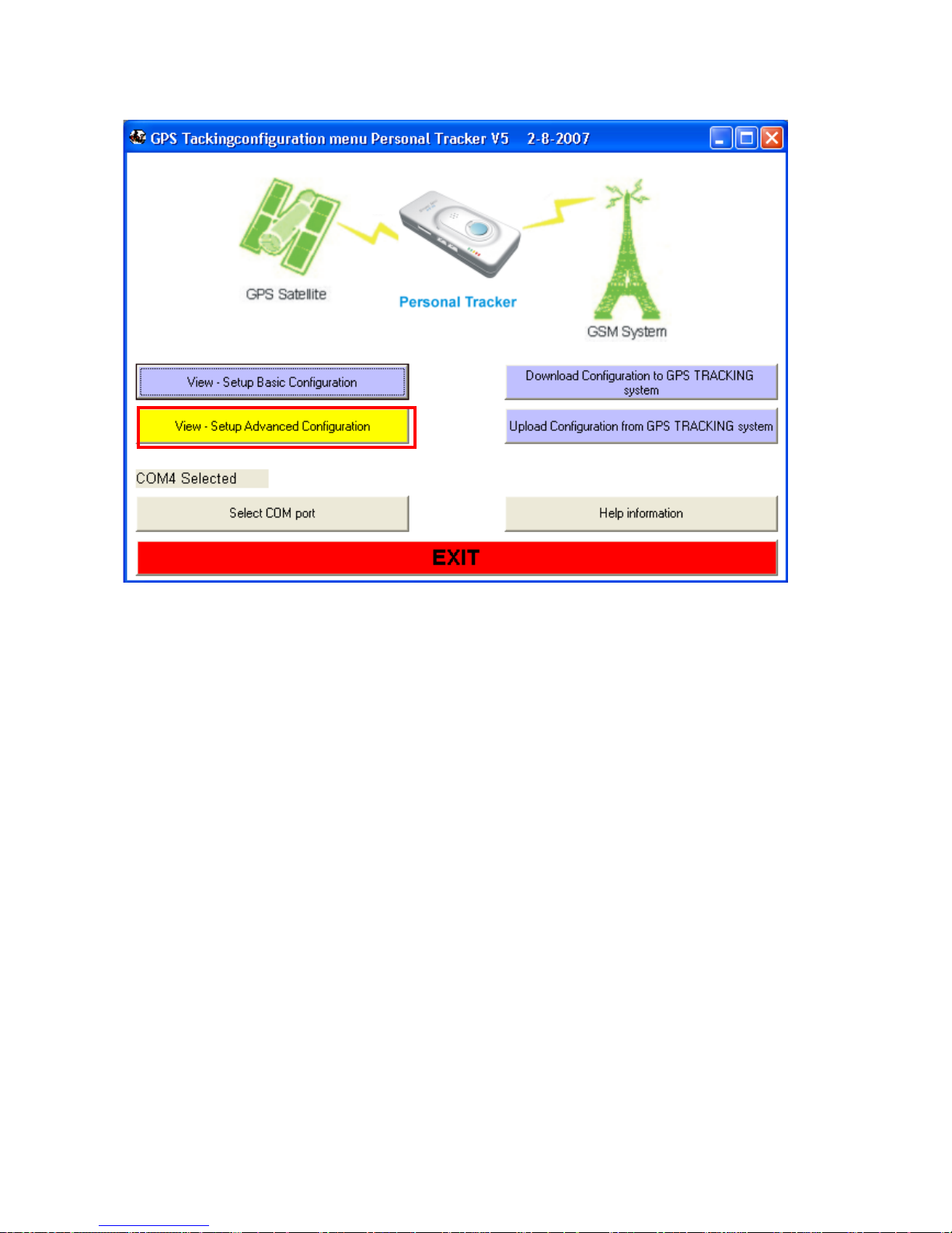
View - Setup Advanced Configuration
22
Page 23
- 23 -
(4)
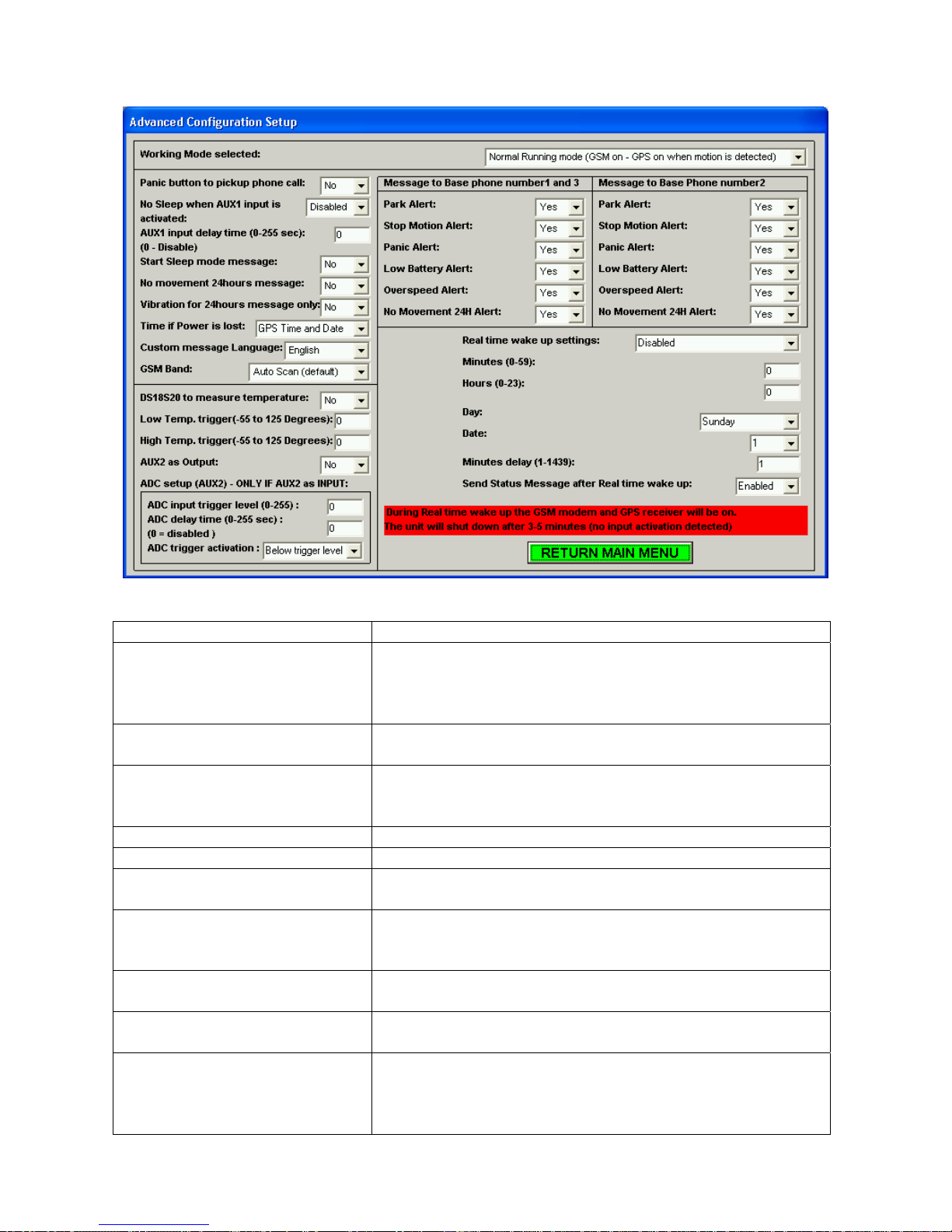
Advanced configuration
Overview (ONLY CHANGE OPTIONS THAT NEED TO BE DIFFERENT)
Settings Description
Working Mode selected: Three different working modes can be selected.
Depending on your applications the working mode
selected can save power consumption. See (1) for more
details.
Panic button to pickup phone
call
No Sleep when AUX1 input is
activated
AUX1 input delay time: Configure delay time before AUX1 is activated
Start Sleep mode message: Send location message when entering sleep mode.
No movement 24hours
message:
Vibration for 24hours message
Only:
Time is Power is lost: Select to use GPS time and date if real time clock is not
Custom message Language: Select different Language for custom message send to
AUX2 as Output : AUX2 can be used as digital output (0 –3.3Volt) or analog
Use the Panic input button to pickup incoming voice call .
See
for more details.
If enabled the WTGAT will NOT enter sleep mode when
AUX1 is low (activated). The AUX1 input delay function is
automatic disabled when this function is enabled.
Send location message when no movement is detected
for 24 hours. See (3) for more details.
When enabled the Vibration sensor is disabled for
WTGAT wake up. It only detects vibration for the 24h
message alert.
configured or time and date is lost
Base phone number2.
input. If selected as output the ADC settings are automatic
disabled. (See ’38’ command code when using AUX2 as
output). See (5)
23
Page 24

- 24 -
(5)
GSM Band Select manual GSM Band. This will force the GSM
modem to only scan and use the selected GSM band.
Normally no need to select manual mode as the GSM
modem will auto scan all GSM bands.
DS18S20 to measure
temperature
Low Temp. trigger(-55 to 125
Select if DS18S20 is connected to measure temperature
See
Configure low trigger temperature when using DS18S20
Degrees)
High Temp. trigger(-55 to 125
Configure high trigger temperature when using DS18S20
Degrees):
ADC setup (AUX2): Configure ADC input trigger level, delay time and trigger
activation. See (5)
Message to Base phone number
1 and 3
Select if message need to be send to Base phone number
1 and 3 when selected input is activated.
Message to Base pone number2 Select if message need to be send to Base phone number
2 when selected input is activated.
Real time wake up settings: Select time for WTGAT to wake up after the WTGAT
enters sleep mode.
Minutes (0-59): Select minute to wake up the WTGAT. If selected the
WTGAT will wake up when minutes match. See (2) for
more information.
Hours (0-23): Select hour to wake up the WTGAT. If selected the
WTGAT will wake up when hours match. See (2) for
more information.
Day: Select day to wake up the WTGAT. If selected the
WTGAT will wake up when day match. See (2) for more
information.
Date: Select date to wake up the WTGAT. If selected the
WTGAT will wake up when date match. See (2) for more
information.
Minutes Delay Select Minutes Delay to wake up the WTGAT. If selected
the WTGAT will wake up after minutes delay selected.
See (2) for more information
Send Status Message after Real
time wake up:
When the WTGAT wakes up during ‘Real time wake up’ it
will try to get valid GPS location (if enabled). Once valid
GPS location is found a status message will be send. If no
valid GPS location is found after 5 minutes then status
message with the last valid GPS location message will be
send. After message is send the WTGAT will wait 3
minutes for any messages received by SMS or GPRS.
(1) The WTGAT has 3 different working modes. What mode selected depends on
your application. To explain how the WTGAT works we use ‘Normal working mode’
and ‘Sleep mode’. In normal running mode the WTGAT can be activated by any
inputs and will process any SMS messages or incoming phone calls.
-Normal Running mode (GSM on - GPS on when motion is detected)
This mode will use most power when selected. The WTGAT will enter normal
running mode when movement or motion is detected and automatic enter sleep
mode after no movement or motion detected for more then 5 minutes. SMS
messages and incoming phone calls will automatic wake up the WTGAT to enter
normal running mode. When the WTGAT enters sleep mode only ADC input
24
Page 25

- 25 -
activation cannot be detected. In sleep mode the GSM led will be on. All other leds
will be off unless battery is charging or battery is low.
-Basic Sleep mode (GSM off - GPS off - Motion/Timer/AUX1/ Panic)
In this mode the WTGAT will not receive any SMS messages, incoming phone calls
or check ADC input for activation.
The WTGAT will wake up to enter normal running mode when motion, Real time
timer time is expired, AUX1 input is activated or Panic input is activated.
The WTGAT will enter sleep mode after 5 minutes if no inputs are activated.
In ‘Basic sleep mode’ all leds will be off unless battery is charging or battery is low.
-Deep Sleep mode (GSM off - GSM off - Timer/ Panic input)
In this mode the WTGAT main power is switched off. The WTGAT will not use any
power from the main battery. The build in backup battery will supply power to the
low power timer chip. Maximum power savings can be archived to allow the WTGAT
to work for several years(*) without battery charge or battery change.
The WTGAT will enter sleep mode after 5 minutes if no inputs are activated.
Park or motion switch will not work when the WTGAT enters ‘Deep Sleep mode’.
In ‘Deep sleep mode’ all leds will be off unless battery is charging or battery is low.
In ‘Deep Sleep mode’ there are only three ways that the WTGAT will wake up.
- The Panic input is activated for more then 4 seconds.
- The low power timer time is expired.
- Wire loop connected to the Panic input is broken (cut) if connected for more
then 4 seconds.
(*) This assumes that the battery has negligible self-discharge
(2) In Sleep mode the WTGAT can wake up when minutes, hours, day or date
matches the internal time or date depending on the ‘Real time wake up settings’
selected.
The following ‘Real time wake up settings’ can be selected from the menu:
- Disabled
- When minutes match
- When hours and minutes match
- When day, hours and minutes match
- When date, hours and minutes match
- After configured minutes delay
Disabled
When selected the WTGAT will not wake up by low power timer.
When minutes match
When selected the WTGAT will wake up when minutes selected match the lo w
power minutes.
Example:
Minutes configured in the configuration menu is 22.
When the low power timer minutes is also 22 then the low power time will wake up
the WTGAT to resume operation in normal running mode.
When hours and minutes match
When selected the WTGAT will wake up when hours and minutes selected match
the low power hours and minutes.
Example:
25
Page 26

- 26 -
Hours configured in the configuration menu is 8.
Minutes configured in the configuration menu is 22
When the low power timer hour is 8 and minutes is 22 then the low power time will
wake up the WTGAT to resume operation in normal running mode.
When day, hours and minutes match
When selected the WTGAT will wake up when Day, hours and minutes selected
match the low power Day, hours and minutes.
Example:
Day configured is Monday.
Hours configured in the configuration menu is 8.
Minutes configured in the configuration menu is 22
When the low power timer Day is Monday and hour is 8 and minutes is 22 then the
low power time will wake up the WTGAT to resume operation in normal running
mode.
When date, hours and minutes match
When selected the WTGAT will wake up when Date, hours and minutes selected
match the low power Date, hours and minutes.
Example:
Date configured is 19.
Hours configured in the configuration menu is 8.
Minutes configured in the configuration menu is 22
When the low power timer Date is 19 and hour is 8 and minutes is 22 then the low
power time will wake up the WTGAT to resume operation in normal running mode.
After configured minutes delay
When selected the WTGAT will wake up after the configured delay in minutes
expires.
Example:
Minutes delay configured is 20.
Just before the WTGAT enters sleep mode the minutes delay time configured is
added to the current time for the next wake up. If the current time is say 12:35:19
then 20 minutes will be added to give next wake up at 12:55:00 (seconds are NOT
added!).
The WTGAT will then resume normal running mode.
Please note that when the WTGAT is in basic sleep mode the ‘Send Location for missed
phone call’ may not respond on the first phone call (GSM modem is on). We suggest
making another phone call about 1 minute after the first call if no message is received.
(3)
If the WTGAT is configured for ‘Deep sleep mode’ then movement will only be detected if
the WTGAT wakes up if wake up interval is configured for ‘Real time wake up settings’ or if
Panic input is activated. During ‘Deep sleep mode’ no movement can be detected.
(4)
This options works as follows:
Once incoming call is received you can use the Panic input to pickup the voice call. The
Panic status (Blue LED) will be ON once the WTGAT has detected that you have pressed
the Panic input button.
26
Page 27

- 27 -
Once the call is connected you can use the Panic button again to disconnect the phone
call. The Blue LED will go OFF once the WTGAT has disconnected the call.
The user has to release the Panic button after the call has been disconnected to prevent
that Panic activation is detected.
(5)
Only one function can be selected at one time for AUX2 (input/output).
4. SMS commands accepted by the tracking unit:
The unit will only process SMS commands sent to the unit. If the unit is configured in SMS and GPRS mode
then any confirm, update or location message is sent back using GPRS.
The unit can read and sent any SMS messages without disconnection from the GPRS connection.
When sending SMS commands please make sure that the message has the correct data format. Some
commands may require a fixed length. Command message must NOT contain any extra spaces, commas or
any other characters. This is very important to make sure the Rover processes the correct command
messages.
11, ( Request Current Status, Version , GPS location)
Example
12, -> SMS only mode (default)
Example:
13, -> SMS and GPRS mode
Example:
14,xxxxxx, -> Update Dail-out number 1 (Max 16 Char)
Example:
15,xxxxxx, -> Update Dail-out number 2 (Max 16 Char)
Example:
16,xxxxxx, -> Update Dail-out number 3 (Max 16 Char)
Example:
17,xxxxxxxxxxxxxxxxxxxxxxxxxxxxxx x x, -> APN for GPRS (31 locations max)
(Default 'internet')
Example: 05*827,17,vodafone,0
18,x, (x = 0 to 9) -> Pickup phone call after x rings.
0 = disable (do not pickup phone call)
Example:
19,x, (x = 0 UDP mode)
(x = 1 TCP mode)
Example:
20, -> Disable Park function
Example:
21, -> Enable Park function.
Will activate if more then 3 vibrations are detected within 30 seconds or speed is more then 5 km/h.
Example:
22, -> Disable Motion alert!
Example:
23, -> Enable Motion alert!
Example:
: 05*827,11,0
05*827,12,0
05*827,13,0
05*827,14,+3124435355,0
05*827,15,+3125111221,0
05*827,16,+310093325,0
05*827,18,3,0 (Pickup after 3 rings)
05*827,19,1,0 (switch to TCP mode)
05*827,20,0
05*827,21,0
05*827,22,0
05*827,23,0
27
Page 28

- 28 -
24,xxxxx, -> TCP Destination Port (6082 decimal – Default – from 0 to 65535)
Example:
25,xxxxx, - > UDP destination Port (6080 decimal – Default- from 0 to 65535)
Example:
26,xxxxxxxxxxxxxxxx, -> ISP login name (24 locations max)
Example:
27,xxxxxxxxxxxxxxxx, -> ISP password name (16 locations max)
Example:
28,x -> ( x= 0 No location message for missed phone call )
( x= 1 Request location message for missed phone call)
Example:
05*827,24,6082,0 - TCP Destination Port !
05*827,25,6080,0 - UDP Destination Port !
05*827,26,guest,0
05*827,27,guest,0
05*827,28,1,0 (Request current or last known location message for missed phone call)
(May not work with all GSM providers or SIM cards)
29,xxxxxxxx, -> IP Destination Address or domain name in ASCII code MAX 32 Char
Example:
30,x, ( x = 0 Power down after Panic input activated (default) )
( x = 1 Do NOT power down after Panic input activated)
Example:
31, ( Erase all GPS locations saved in Memory)
Example:
THIS COMMAND MUST NOT BE USED IN COMBINATION WITH OTHER COMMANDS!
NO CONFIRM MESSAGE WILL BE RETURNED!
This command will reset your WTGAT and startup will be delayed between 30 to 60 seconds.
32,x, ( x = 0 No battery low warning message )
( x = 1 Battery low warning message when battery <20%)
Example:
33,x, ( x = 0 No resend for messages that cannot be sent )
( x = 1 Resend messages that cannot be sent)
Example:
34,x, ( x = 0 Do NOT add IMEI number to SMS messages)
( x = 1 Add IMEI number to SMS messages)
Example: 05*827,34,1,0 (Add IMEI number to SMS message)
35,x, ( x = 0 Use GPS Time and Date if low power timer time and date is lost)
( x = 1 Do not update Time and Date using GPS Time and Date if lost)
Example:
* Time and date can only be updated to GPS time and date after Valid GPS location and WTGAT
running in ‘Normal’ running mode.
36, ( Request ‘Real time clock’ time and date)
THIS COMMAND MUST NOT BE USED IN COMBINATION WITH OTHER COMMANDS!
Example
Will return:
05*827,29,www.newtrack.com.tw,0
05*827,30,0,0 (Messages to Base 1)
05*827,31,0 (Clear all GPS locations)
05*827,32,0,0 (disable low battery warning message)
05*827,33,1,0 (Resend messages that cannot be sent)
05*827,35,0,0 (Use GPS Time and Date if low power timer time and date is lost)
: 05*827,36,0
05*827,CONFIRM,36,<time>,<date>,0 <,IMEI optional if enabled>
(05*827,CONFIRM,36,12:23:01,12-08-07,0)
37, ( Request location sequence)
Will return 4 locations messages (if valid locations) or 1 single location if invalid or last known.
Example
38,x, (Activate or deactivate the AUX2 output)
( x = 0 Deactivate the AUX2 output (low))
: 05*827,37,0
28
Page 29

- 29 -
y
( x = 1 Activate the AUX2 output (high))
Example
: 05*827,38,1,0 - Activate the AUX2 output (high)
* PLEASE NOTE THAT THE AUX2 OUTPUT MUST BE CONFIGURED AS OUTPUT OTHERWISE THE
FUNCTION WILL NOT WORK
If power is lost or the WTGAT enters deep sleep mode the output will deactivate (no power on output).
At power startup the output will be low (0). The AUX2 output will return to activate high or low depending on
the status before power down. You can test the AUX2 as output in normal running mode by pressing the ‘B’
or ‘b’ key. The following messages will be displayed.
'AUX2 as output active HIGH' (AUX2 will be active high for 5 seconds)
'AUX2 as output active LOW' (AUX2 will be active low for 5 seconds)
After 10 seconds the WTGAT will return to normal running mode.
39,<time date>,
Example
: 05*827,39,03:19:21 15-04-09,0 - Set time to 3:19:21 in the morning and date to 15-4-2009
The correct format for time and date must be used otherwise the time and date will NOT be updated.
Time must be in 24 hour format (hours between 00 to 23, minutes between 00 to 59, seconds between 00 to
59) and date as day-month-year (day between 01 to 31, month between 01 to 12, year between 00 to 99).
40,x, - > Real time wake up settings:
(x=0 -> Disabled)
(x=1 -> When minutes match)
(x=2 -> When hours and minutes match)
(x=3 -> When day, hours and minutes match)
(x=4 -> When date, hours and minutes match minutes match)
(x=5 -> When added minutes delay match)
Example:
05*827,40,1,0 - Wake up when minutes match
41,xx, Configure minutes for ‘Real time wake up’ – MUST be 2 DIGITS!
Where ‘xx’ must be between 00 and 59.
Example:
05*827,41,15,0 - Select 15 minutes as minute wake up time.
42,xx, Configure hours for ‘Real time wake up’ – MUST be 2 DIGITS!
Where ‘xx’ must be between 00 and 23.
Example:
05*827,42,03,0 - Select 3 AM as hour wake up time.
43,x, Configure Day for ‘Real time wake up’
Where ‘x’ must be between 1 and 7.
Where:
1 Sunday
2 Monda
3 Tuesday
4 Wednesday
5 Thursday
6 Friday
7 Saturday
Example:
05*827,43,3,0 - Select Tuesday as wake up time.
44,xx, Configure Date for ‘Real time wake up’ up’ – MUST be 2 DIGITS!
Where ‘xx’ must be between 01 and 31.
Example:
05*827,44,23,0 - Select 23 as Date wake up time.
45,x, - > (x=0 -> Send status message after Real time wake up (default)*
(x=1 -> Do NOT send status me ssage after ‘Real time wake up’)
Example:
05*827,45,0,0 - Send status message after ‘Real time wake up’
29
Page 30

- 30 -
* Status message is send when valid GPS location is found. If no valid GPS location is found during
‘Real time wake up’ then status message will be send after 5 minutes. After message is send the
WTGAT will wait another 3 minutes for any SMS messages returned before returning to sleep mode.
46,xx, - > Configure wake up delay time in minutes when entering sleep mode.
Must be in Hex format (001 to $59F) – MUST be 3 DIGITS!
When configured the WTGAT will wake up when the configured delay time expires.
Example:
Just before the WTGAT enters sleep mode the wake up delay time will be added to the current time from the
real time clock. As example the current time is 12:05:20 (before entering sleep mode) and the wake up delay
time in minutes is 46 (as example above) then the WTGAT will wake up at 12:47:00. Every time the WTGAT
enters sleep mode the wake up delay time is added to the current time.
47,x, - > (x=0 -> AGPS data upload disabled)
(x=1 -> Enable AGPS data upload)*
Example:
* AGPS data upload used GPRS communication. You need to be registered before data can be uploaded.
The WTGAT will automatic download the AGPS data support file every 13-14 days.
5,xxxxxx..x, (xxxxx.x New Base1 Phone number for Track ing unit ) -16 Digits max.
Example:
51,x, - > (x=0 -> Normal running mode – GSM on when in sleep mode)
(x=1 -> Basic sleep mode – GSM and GPS off)
(x=2 -> Deep sleep mode – GSM and GPS off)
Example: 05*827,51,1, 0 - Enable Basic sleep mode
52,aa,bb,c,
aa = Delay time ADC input (in Hex from 00 to FF) - 00 = disabled - MUST BE 2 DIGITS!
bb = ADC input trigger level (in Hex from 00 to FF) - MUST BE 2 DIGITS!
c = 0 - Below trigger level
1 - Above trigger level
Example:
53,xxxxxx..x, (xxxxx.x New Base2 Phone number for Tracking unit) -16 Digits max.
Example:
To configure empty (none) phone number use the ‘05*827,53,,0’ command
55,x, (Custom message to Base2)
x=0 -> Disabled
x=1 -> Enabled
Example:
56,xxxxxx..x, (xxxxx.x New SMSC number ) - (16 Digits max).
Example:
To configure empty (none) phone number use the ‘05*827,56,,0’ command
57,xxxxxx..x, (xxxxx.x New Phone number for Third Tracking base Phone)- (16 Digits max).
Example:
To configure empty (none) phone number use the ‘05*827,57,,0’ command
58,x, - > (x=0 -> Speaker on (default)
(x=1 -> Internal and external (if connected) Speaker off)
Example:
59,x, (x=0 -> Do not activate buzzer for 1 second after Panic message send successful)
(x=1 -> Activate buzzer for 1 second after Panic message send successful )
Example:
60,x, (x=0 -> Dial out first if Panic input is activated (if Dial out numbers are configured)
05*827,46,02A,0 - Wake up after 42 (Hex 02A) minutes.
05*827,47,1,0 - Enable AGPS data upload
05*827,5,+6790887676,0 - new Base1 Phone number is +6790887676.
05*827,52,2F,5B,1,0 - Delay time is 47 seconds, Trigger level is 91 and trigger above value.
05*827,53,+8932324,0 - new Base2 Phone number is +8932324.
05*827,55,1,0 - Custom message enabled to Base2.
05*827,56,+12232443,0 - new SMSC number is +12232443
05*827,57,+12232443,0 - new Base3 Phone number is +12232443
05*827,58,1,0 - Internal and external (if connected) Speaker off
05*827,59,1,0 - Activate buzzer for 1 second after Panic message send successful
30
Page 31

- 31 -
(x=1 -> SMS/GPRS message(s) first )
Example:
05*827,60,1,0 - Send any SMS/GPRS messages first before dialling out.
63,xx, AUX1 input delay time in HEX from 00 to FF ( xx=00 AUX1 input disabled ) – MUST be 2 DIGITS!
Example:
05*827,63,1B,0 - Send message when activated for more then 27 seconds.
64,xx,yy,
(xx= speed limit from 00 to FF (255 hex) max – MUST be 2 DIGITS! – VALUE in Knots !!!!)
(yy=00 Speed check disabled)
(yy=01 to FF (255 hex) seconds above speed limit before activation– MUST be 2 DIGITS!)
Example:
05*827,64,35,05,0 - Send message when speed more than 100 km/h for 5 seconds
( 1 knot is 1.852 km/h)
67,x, -> Panic input enabled / disabled
(x=0 Disabled )
(x=1 Enabled - Default)
Example:
05*827,67,1,0 - Panic input Enabled!
68,xx, -> Vi bration Sensitivity - Enter value in Hex – MUST BE 2 DIGITS!
(x=64 (hex)-> Default)
(x=FF (hex)-> MAX )
* Less will make the vibration switch more sensitive. Zero (0) will disable vibration detection and the WTGAT
will not enter sleep mode! Max value (FF (hex) – 255 Decimal) will disable vibration detection. The WTGAT
will not detect any vibration and will not wake up from vibration.
Example:
05*827,68,64,0
79,xxxx, -> Real time tracking interval – SMS or GPRS -> configured in Hex! for ONLINE mode
MUST BE 4 DIGITS!
-> Real time tracking interval -> configured in Hex!
(xxxx = 0000 -> NO Real time tracking! - Default after operating system update or
Reset)
(xxxx = 0001 -> Send 1 message every 4 seconds)
(xxxx = 0002 -> Send 1 message every 8 seconds)
(xxxx= 0003 -> Send 1 message every 12 seconds)
(xxxx = 0004 -> Send 1 message every 16 seconds)
etc. Max xxxx = 3FFF (hex)
(xxxx = 3FFF (hex) -> Send 1 message every 65532 seconds max)
Example:
05*827,79,0005,0 - Send 1 message every 20 seconds
9x, Enable or disable communi cation from tracking unit.
The unit will still accept update messages, but no locations messages or input activations messages are
send.
( x=0 Disable Tracking unit ; x=1 Enable Tracking unit)
Example:
05*827,91,0 - Enable tracking unit.
A0,x -> Enable commands from other Base phone numbers
x=0 -> Disable
x=1 -> Enable
Example:
05*827,A0,1,0 (Enable commands from other Base phone numbers)
A1,xxxxxxxxxx -> Security ID code (Must be 10 Digi ts)
xxxxxxxxxx -> 10 Digit security code (can be any numbers or letters)
Example:
05*827,A1,Ab1245678a,0 (Change ID code to ‘Ab1245678a’ )
A2,x -> ( x=0 Stay connected to GPRS in sleep mode )
( x=1 Disconnect from GPRS in sleep mode )
31
Page 32

- 32 -
Example:
A confirm message will be returned.
A3,x -> ( x=0 Do not stop real time tracking when roaming)
( x=1 Stop real time tracking when roaming )
Example:
When enabled will stop sending real time data when SIM card is roaming. All other messages are still sent.
A confirm message will be returned.
All return messages are send-using Base1, 2 or 3 depending on the command received and your
configuration settings.
The message received does not have to start with ‘05*827’.
Example:
Message sent: [email protected] 05*827,0123456789,11,0
Will be accepted and processed.
05*827,A2,1,0 (Disconnect from GPRS in sleep mode)
05*827,A3,1,0 (Stop real time tracking when roaming)
WARNING:
Default security code is ‘0123456789’ and the option is automatic disabled after operating system upload.
We strongly recommend for your network to keep secure to change the ‘Security ID code’ first and do not
leave it set to ‘0123456789’.
Base phone number 2 can receive the following End user text messages:
- Park Alert Activated
- Stop MOTION Alert Activated
- PANIC Button Activated
- Low Battery Voltage
- OVERSPEED Alert No Movement 24 Hours Alert
The configuration menu allows to choose different language for custom message to Base phone
number 2. Default language is English.
Unit activation and sleep Mode:
The tracking unit has a build in ‘motion’ sensor that detects any movement and g-force change.
The WTGAT will enter ‘sleep’ mode after 5 minutes if no ‘motion’ is detected. In sleep mode the GPS
module is powered down, but the unit will still process any incoming and outgoing SMS messages if ‘Normal’
running mode is selected.
When the unit is in ‘Normal’ and ‘Basic sleep mode’ it will take several seconds to ‘wake up’ to normal
running mode after motion is detected. Motion is normally detected when you move the unit.
A valid GPS location can take several seconds to several minutes (depending if the WTGAT had valid GPS
location before and the time when there was last valid GPS location) after the unit is operating in normal
running mode (GPS aerial has clear sky view).
Software and hardware lock-ups:
The unit has an internal har dware timer that detects ‘lock-up’.
If the unit is ‘locked’ in it automatic ‘reset’ after 5-10 minutes.
32
Page 33
- 33 -
5. Uploading the Operating System to the WTGAT
The firmware file should have an extension file name “.s19”.
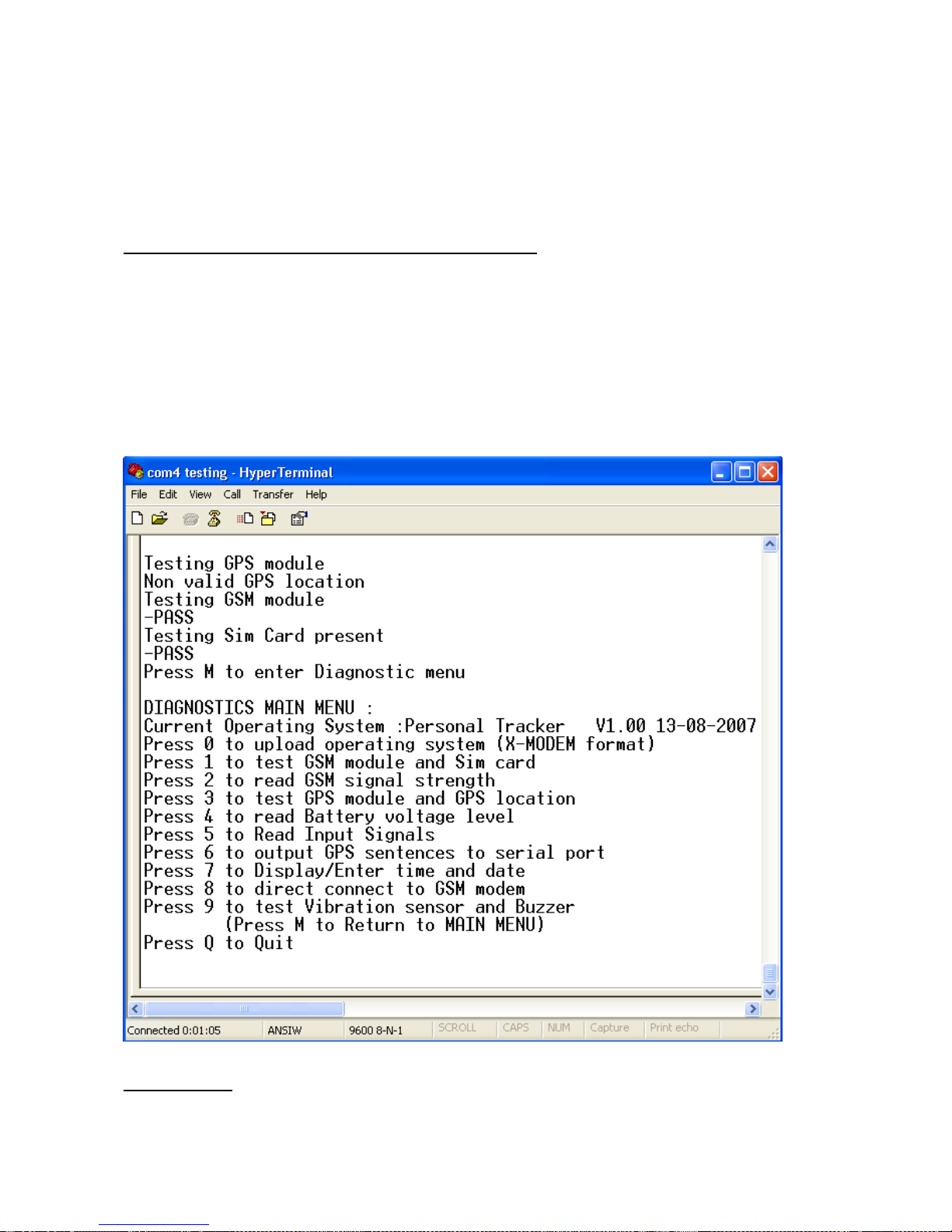
When the Rover module is connected to the serial port of a computer and it is in Diagnostic mode,
A new or modif ied Operating System can be uploaded to the Rover module by pressing 0.
The new or modified Operating System will be distributed in the X-Modem format. It will be a small file that is
capable of being distributed to installers by email.
Once you hav e received the new operati ng system by ema i l place it in a new folder on your computer (we
would recommend calling the folder WTGAT).
· With the WTGAT connected to the computer and in Diagnostic mode press 0 to begin the upload.
*PLEASE NOTE
Update the ‘operating system’ does not delete or change any saved GPS locations, Base phone number or
dial out phone numbers.
33
Page 34
- 34 -
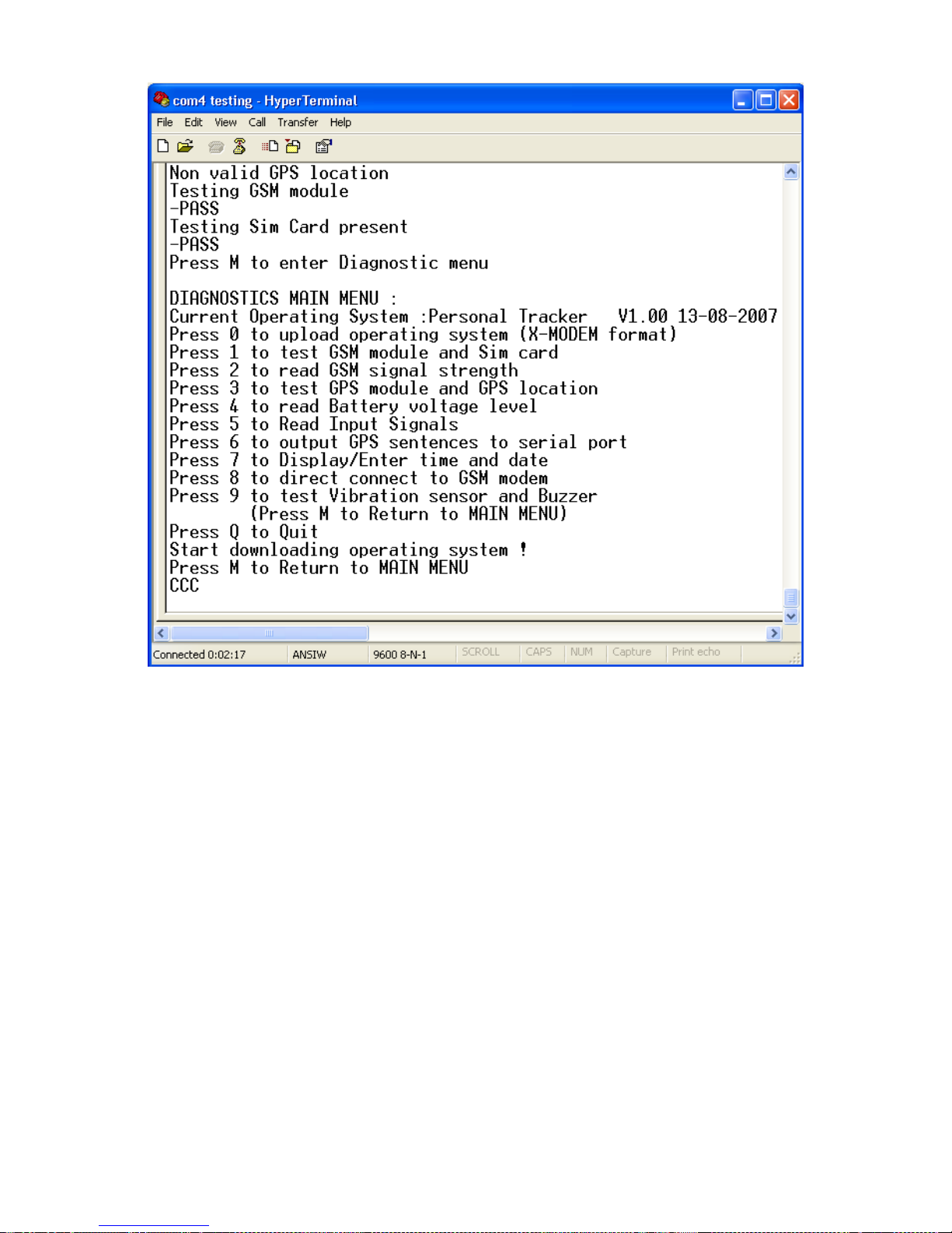
· On the HyperTerminal main screen click on Transfer and then Send File from the drop down list.
· Click Browse to locate the folder that contains the Operating System file. Highlight the file and click Open.
· Then click Send File. The download will begin.
34
Page 35
- 35 -
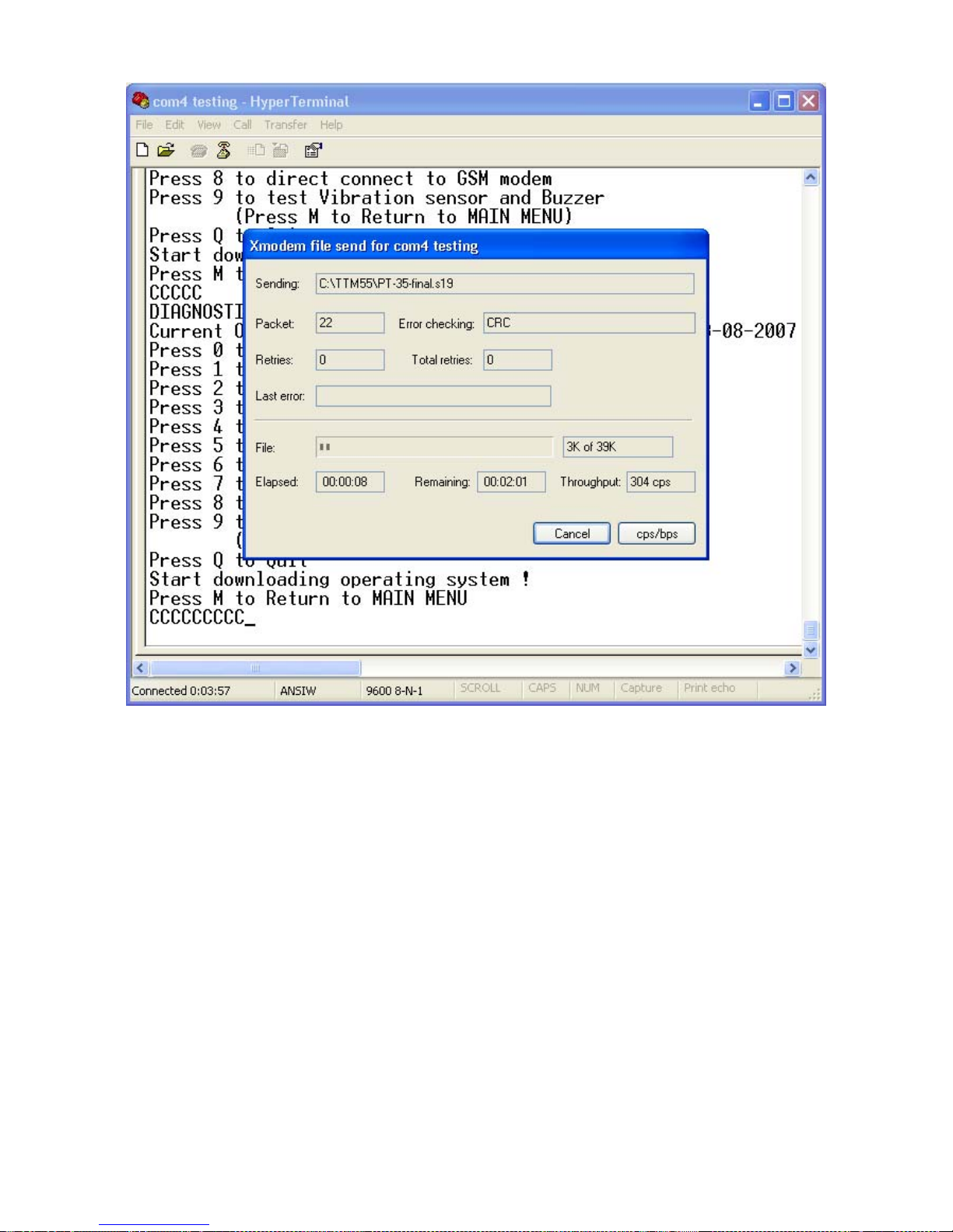
After upload the WTGAT unit will restart into the Diagnostic Main Menu. The Version and Date details of
the new Operating System will be displayed.
35
Page 36

- 36 -
6. Messages send by WTGAT:
Message from the WTGAT can be send using SMS or GPRS. In SMS only mode all data is sent using SMS.
In SMS and GPRS mode all messages are sent using GPRS. If SMS and GPRS mode is enabled and GPRS
is not availa ble then any inpu t activations will be sent using SMS. Whenever GPRS is available again the
unit will use GPRS again. In case real time tracking is enabled in SMS and GPRS mode and GPRS is not
available then the unit can send the data using SMS if enabled (see configuration menu).
If GSM signal is not available and input is activated then the tracking unit will send the alarm message as
soon as there is GSM signal again. The time and date in the message is from the GPS time and date at the
time the message is sent.
If real time tracking is enabled and there is no GSM signal then the information will be lost. The tracking unit
will still save GPS locations using the ‘GPS reading/saving interval setting’ if the GPS location is valid.
1. Location Message.
2. Confirm Message for Update.
3. Missed messages for real time tracking.
1.Location Message:
The data length is always the same!
Sample:
05*850,000,PT35,A,2459.3640,N,12125.2958,E,000.0,224.8,00.8,07:47:26 09-0905,1.00,80,3F,353425142654345
ID Code (6 Bytes in ASCII), Status code (3 Bytes in ASCII), Unit number, Status (A or V), Latitude, N/S
indicator, Longitude, E/W Indicator, speed, Course, HDOP, GPS time lat/lon value - GPS date lat/lon value,
Unit Version number, battery power level, ADC voltage level, <IMEI number if option enabled>
ID CODE:
The ID code can be 05*850 or 05*827.
05*850 is returned when the unit has received a request message from base to send a
location message.
05*827 is returned if any input is activated.
STATUS CODE:
Sent in ASCII code for text message. Add $30 to First, Second and Third Code.
; First code:
; 1 = Battery power low <20%
; 2 = Motion alert al a r m
; 4 = Park alert alarm
; 8 = Entering Sleep mode message
; 16 = Temperature from Digital Thermometer (DS18S20) above or below the configured value
; Second Code:
; 1 = Panic Button Activated
; 2 = Motion detection alarm enabled
; 4 = Park detection alarm enabled
; 8 = 24 Hour no motion alarm activated
; Third Code:
; 1 = Vehicle traveled above MAX configured speed limit
; 2 = AUX1 input activated
; 4 = ADC activated
; 8 = 0 -> Positive temperature reading
; 1 -> Negative temperature reading
36
Page 37

- 37 -
The ASCI conversion (samples):
First code is: 0 (ASCII code is 48)
To find the status code value subtract 48 from the ASCII code to find the status value 0.
First code is: 7 (ASCII code is 55)
To find the status code value subtract 48 from the ASCII code to find the status value 7.
First code is: = (ASCII code is 61)
To find the status code value subtract 48 from the ASCII code to find the status value
13.
ASCII table conversion used:
0 = 48 5 = 53 : = 58 ? = 63 D = 68
1 = 49 6 = 54 ; = 59 @= 64 E = 69
2 = 50 7 = 55 < = 60 A = 65 F = 70
3 = 51 8 = 56 = =61 B = 66 G = 71
4 = 52 9 = 57 > = 62 C = 67 H = 72
I = 73 N=78
J = 74 O=79
K= 75
L = 76
M=77
Unit number:
Always 4 char: WTAT
Status (A or V):
GPS status:
A = Valid GPS location
V = NON Valid GPS location
For NON Valid location the time and date is from the last time the location was valid!
If location has never been valid before then time and date is time and date from the
Real time Clock.
Latitude:
Always the same format xxxx.xxxx
N/S indicator:
N = North
S = South
Longitude:
Always the same format xxxxx.xxxx
E/W Indicator:
E = East
W = West
Speed:
Value in Knots.
Always the same format xxx.x
Course:
Course in degrees.
Always the same format xxx.x
HDOP:
Horizontal Dilution of Precision.
Always the same format xx.x
GPS time:
Format as hh:mm:ss
37
Page 38

- 38 -
Example : 07:47:26
GPS date:
Format as dd-mm-yy
Example: 09-09-05
Unit Version number:
Format as x.xx
Example: 1.00
Battery level Status (value decimal in % from 00 to 99):
ADC voltage level:
Will always be shown as 2 digits. From 00 to FF (hex).
When configured as input (ADC conversion) the value will be between $00 and $FF (255 max).
When configured as output this value will be $FF (255).
When configured to use external digital thermometer (DS18S20) the output value will be between $00 and
$FF (255 max).
2. Confirm Message:
A confirm message will be sent whenever the tracking unit receives a command to update
a setting.
The WTGAT has 3 Base phone numbers that can be configured to allow configuration
setup.
Information that is received from the 3 Base phone numbers is processed as
follows:
Base 1:
Master Base phone number. Accepts all command messages and update
messages. Location request or configuration update messages are sent back to Master
Base phone number if unit is configured for SMS only.
In combined working mode (SMS and GPRS) the location request or configuration update
message is sent back using GPRS.
Base 2:
The following message(s) can be displayed:
This phone number can be used by the ‘End User’ to receive a ‘Pager’ message.
PARK Alert Activated
Stop MOTION Alert Activated
PANIC Button Activated
Low Battery Voltage
OVERSPEED Alert
No Movement 24 Hours Alert
The ‘End User’ will also receive a confirm message(*) if the option is enabled or disabled
by the Base 1 or Base 3 phone number.
(*) Only if option can be enabled or disabled by SMS or GPRS command.
Park Alert is activated when the WTGAT detects a speed faster then 5km/h or 3
movements within 30 seconds. After the message is send the PARK Alert function will
automatic reactivate after 60 seconds (if Park switch is ON only!). Message sending when
activated is delayed for 20 seconds when activated when enabled using the PARK switch.
38
Page 39

- 39 -
This will give the user time to switch off the PARK switch.
Base 3:
Master Backup Base phone number. Accepts all command messages and update
messages. Location request or configuration update messages are sent back to Master
Backup Base phone number only.
In combined working mode (SMS and GPRS) the location re quest or configuration update
message is also sent back to Master Backup Base phone number.
The Master Backup phone number will also receive input alarm activation messages
(Panic, Park, Power loss detected etc.) as ‘location format’ message.
Confirm message format:
05*827,CONFIRM,xx,x1,x2, ,0 <,IMEI optional if enabled>
Where xx, x1, x2 etc is the command code setting that has been updated.
The xx can have the following settings:
12,13,17,19,20,21,22,23,24,26,27,28,29,30,32,5,51,53,55,56,56,64,66,67,68,74,79,90,91,A0,A1,A
2,A3
12 = Unit is configured for SMS messages only. All data is sent using SMS.
13 = Unit will work in combined GPRS and SMS mode.
14 = Dial-out number 1 updated.
15 = Dial-out number 2 updated.
16 = Dial-out number 3 updated.
17 = APN number has been updated.
18 = Pickup phone calls updated.
19 = GPRS sending data mode has been updated (UDP or TCP).
20 = Disable Park function confirm.
21 = Enable Park function confirm
22 = Disable Motion alert confirm
23 = Enable Motion alert confirm
24 = TCP data mode port updated.
26 = ISP login name for GPRS updated.
27 = ISP password name for GPRS updated.
29 = Static IP address or domain name for GPRS data updated.
30 = Messages to Base Phone number 1 ONLY updated.
32 = Battery low warning updated.
33 = Message resend has been updated.
34 = Add IMEI number to SMS messages updated.
35 = Time and Date update using GPS updated.
38 = AUX2 output activated
39 = Real time clock time and date updated.
40 = Real time wake up settings updated.
41 = Minutes for real time wake up settings updated.
42 = Hours for real time wake up settings updated.
5 = Master Base phone number updated
51 = Sleep mode options updated (will reset the WTGAT after update)
53 = Base 2 phone number updated.
55 = Custom message settings for Base 2 updated.
56 = SMSC number updated.
57 = Master Backup Base phone number updated.
64 = Speed settings updated.
66 = Real time tracking interval settings OFFLINE updated.
67 = Panic input settings updated.
68 = Vibration sensitivity settings updated.
39
Page 40
- 40 -
74 = Reset WTGAT system activated.
79 = Real time tracking interval settings ONLINE updated
90 = Tracking unit disabled.
91 = Tracking unit enabled.
A0 = Enable commands from other Base phone numbers.
A1 = Security ID code updated.
A2 = Connected to GPRS in sleep mode updated
A3 = Disconnect from GPRS in sleep mode updated.
3. Message that cannot be send:
The WTGAT will automatic save location and activation messages to memory. If ‘Resend Missed
locations’ is enabled and the message cannot be send then the message(s) that where not send
will automatic be resend.
Depending on your communication mode selected (SMS Only or SMS and GPRS) the messages
are send back using SMS or GPRS.
Up to 5000+ locations can be send back.
Example:
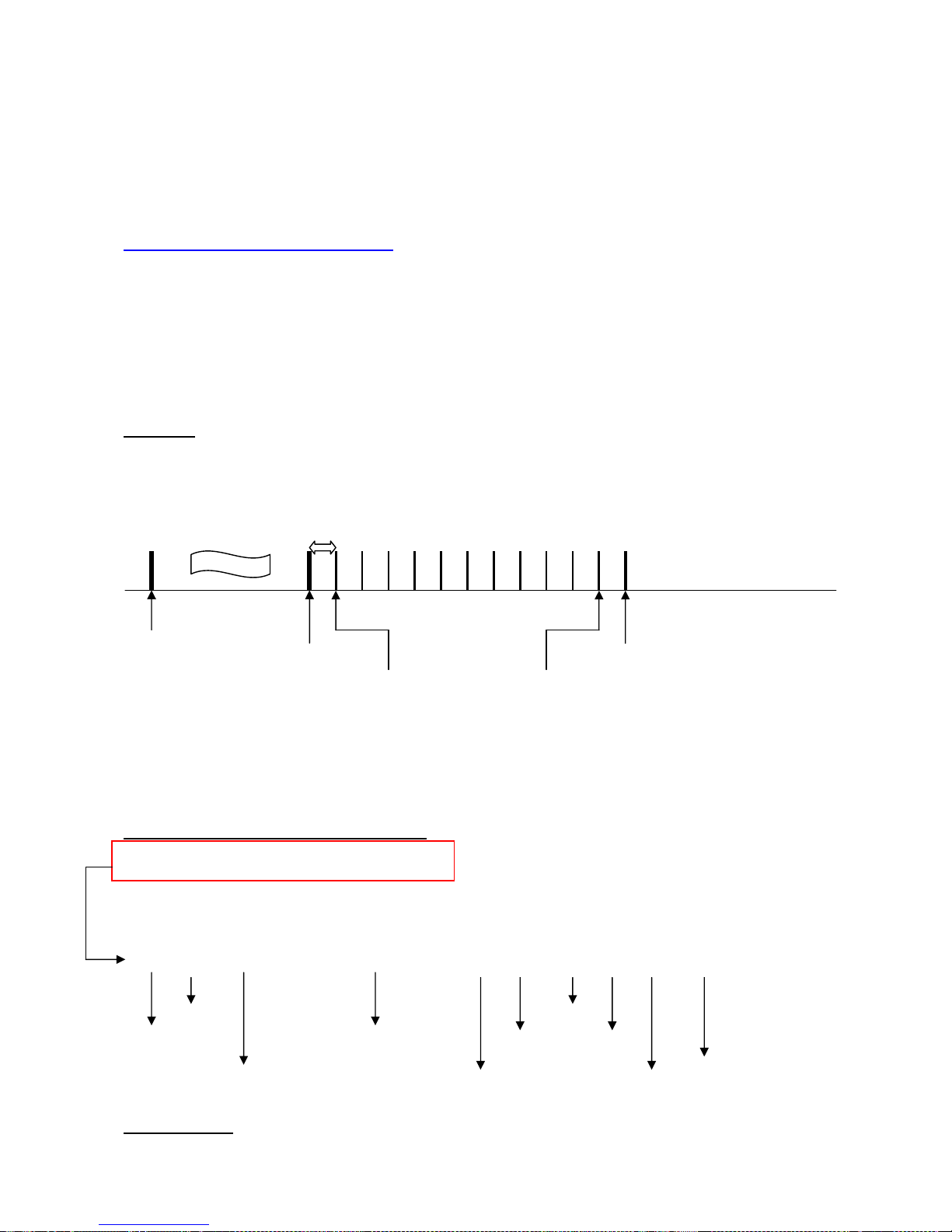
Real time tracking is enabled and configured to send message every 60 seconds using SMS.
While moving you enter a location where there is no GSM signal. You stay at that location for 12
minutes. After that you returned to a location where there is GSM signal.
12
1 Minute 11 9 8 7 6 5 4 3 2 1
*
GSM Signal No GSM Signal GSM Signal
First location saved Last location saved
When the next real time tracking location (*) needs to be sent back and the transmission is
successful the WTGAT will try to send back the missed locations. Missed locations are sent back
starting from the last saved location (1). One message (SMS or GPRS) will contain 4 locations.
Example message showing 4 locations:
00012459374312125290900000003iFG8699.00012459374312125290900000003i0G8699.000124
59374312125290900000003hrG8699.00012459374312125290900000003hqG8699.
The message can be decoded as follows:
000 1 24593743 121252909 0 000 000 3iF G86 99.
Valid/Non valid Direction
Status Longitude Speed Time
Code
Latitude Latitude/Longitude Hemisphere Date ADC value
STATUS CODE:
40
Page 41

- 41 -
Sent in ASCII code for text message. Add $30 to First, Second and Third Code.
; First code:
; 1 = Battery power low <20%
; 2 = Motion alert al a r m
; 4 = Park alert alarm
; 8 = Entering Sleep mode message
; 16 = Temperature from Digital Thermometer (DS18S20) above or below the configured value
; Second Code:
; 1 = Panic Button Activated
; 2 = Motion detection alarm enabled
; 4 = Park detection alarm enabled
; 8 = 24 Hour no motion alarm activated
; Third Code:
; 1 = Vehicle traveled above MAX configured speed limit
; 2 = AUX1 input activated
; 4 = ADC activated
; 8 = 0 -> Positive temperature reading
; 1 -> Negative temperature reading
The ASCI conversion (samples):
First code is: 0 (ASCII code is 48)
To find the status code value subtract 48 from the ASCII code to find the status value 0.
First code is: 7 (ASCII code is 55)
To find the status code value subtract 48 from the ASCII code to find the status value 7.
First code is: = (ASCII code is 61)
To find the status code value subtract 48 from the ASCII code to find the status value
13.
ASCII table conversion used:
0 = 48 5 = 53 : = 58 ? = 63 D = 68
1 = 49 6 = 54 ; = 59 @= 64 E = 69
2 = 50 7 = 55 < = 60 A = 65 F = 70
3 = 51 8 = 56 = =61 B = 66 G = 71
4 = 52 9 = 57 > = 62 C = 67 H = 72
I = 73 N=78
J = 74 O=79
K= 75
L = 76
M=77
Valid or Non Vali d GPS location:
0 = Non Valid or last known GPS location
1 = Valid GPS location
Latitude:
Always the same format (Example: 24593743 -> 2459.3743) - (xxxx.xxxx)
values in ddmm.mmmm
dd in decimal
mm (after dd) IN MINUTES (00 to 59)
mmmm (after dot .) in decimal (0000 to 9999))
Longitude:
Always the same format (Example: 121252909 -> 12125.2909) – (xxxxx.xxxx)
values in dddmm.mmmm
ddd in decimal
mm (after dd) IN MINUTES (00 to 59)
mmmm (after dot .) in decimal (0000 to 9999))
Latitude/Longitude Hemisphere:
41
Page 42

- 42 -
0 = NE , 1 = SE , 2 = NW , 3 = SW
Speed:
Value in Knots.
Always the same format xxx (first 3 digits only)
Course:
Course in degrees.
Always the same format xxx (first 3 digits only)
GPS time:
Time is compressed to 3 digits.
It can be easy converted back.
Example as shown:
The first digit represent hour. To convert back you must use the ASCII table.
The ASCII value for ‘3’ is 51 (Hex 32). Subtract 48 to find the number = 3.
If the ASCII value is less then 90 (Hex 5A) then you must subtract 48 to get the number.
If the ASCII value is more then 90 (Hex 5A) then you must subtract 55 to get the number.
The second digit represent minutes. To convert back you must use the ASCII table.
The ASCII value for ‘i’ is 105 (Hex 69). Subtract 55 to find the number = 50.
If the ASCII value is less then 90 (Hex 5A) then you must subtract 48 to get the number.
If the ASCII value is more then 90 (Hex 5A) then you must subtract 55 to get the number.
The third digit represent seconds. To convert back y ou must use the ASCII table.
The ASCII value for ‘F’ is 70 (Hex 46). Subtract 48 to find the number = 22.
If the ASCII value is less then 90 (Hex 5A) then you must subtract 48 to get the number.
If the ASCII value is more then 90 (Hex 5A) then you must subtract 55 to get the number.
The time shown in the example is : 03:50:22
GPS date:
date is compressed to 3 digits.
It can be easy converted back.
Example as shown:
The first digit represent day. To convert back you must use the ASCII table.
The ASCII value for ‘G’ is 71 (Hex 47). Subtract 48 to find the number = 23.
If the ASCII value is less then 90 (Hex 5A) then you must subtract 48 to get the number.
If the ASCII value is more then 90 (Hex 5A) then you must subtract 55 to get the number.
The second digit represent month. To convert back you must use the ASCII table.
The ASCII value for ‘8’ is 56 (Hex 38). Subtract 48 to find the number = 8.
If the ASCII value is less then 90 (Hex 5A) then you must subtract 48 to get the number.
If the ASCII value is more then 90 (Hex 5A) then you must subtract 55 to get the number.
The third digit represent year. To convert back you must use the ASCII table.
The ASCII value for ‘6’ is 54 (Hex 36). Subtract 48 to find the number = 6.
If the ASCII value is less then 90 (Hex 5A) then you must subtract 48 to get the number.
If the ASCII value is more then 90 (Hex 5A) then you must subtract 55 to get the number.
The date shown in the example is: 23.08.2006
ADC value:
Will always be shown as 2 digits. From 00 to FF (hex).
When configured as input (ADC conversion) the value will be between $00 and $FF (255 max).
When configured as output this value will be $FF (255).
When configured to use external digital thermometer (DS18S20) the output value will be between $00 and
$FF (255 max).
Each location is separated by a dot (.).
3iF
G86
42
Page 43
- 43 -
The missed messages for real time tracking can have 1 to 4 locations (max) in each message.
So in the above example we will receive 3 messages that have 4 locations.
If we have only 2 saved locations we will only receive 1 message that has 2 locations.
Up to 25 messages are transmitted per real time tracking interval sending. This will allow the tracking system
to process other messages in case many location messages that need to be send back to base.
Example:
There are 130 missed messages saved to memory.
For the first real time tracking interval the unit will transmit 100 locations.
The last 30 messages will be sent after the second real time interval.
Conversion help for multiple location messages:
Example message showing 4 locations:
00012459374312125290900000003iFG8699.00012459374312125290900000003i0G8699.000124
59374312125290900000003hrG8699.00012459374312125290900000003hqG8699.
The message can be decoded as follows:
000 1 24593743 121252909 0 000 000 3iF G86 99.
Valid/Non valid Direction
Status Longitude Speed Time
Code
Latitude Latitude/Longitude Hemisphere Date ADC value
* = Depends what function is selected for the this input
Conversion table for Time and Date digits:
0 = 0 G = 23 e =46
1 = 1 H = 24 f =47
2 = 2 I = 25 g =48
3 = 3 J = 26 h =49
4 = 4 K = 27 I =50
5 = 5 L = 28 j =51
6 = 6 M = 29 k =52
7 = 7 N = 30 l =53
8 = 8 O = 31 m =54
9 = 9 P = 32 n =55
: = 10 Q = 33 o =56
; = 11 R = 34 p =57
< = 12 S = 35 q =58
= = 13 T = 36 r =59
> = 14 U = 37
? = 15 V = 38
@ = 16 W = 39
A = 17 X = 40
B = 18 Y = 41
C = 19 a = 42
D = 20 b = 43
E = 21 c = 44
F = 22 d = 45
43
Page 44

- 44 -
The above sample time will be:
Time = '3iF' = 03:50:22
The above sample date will be:
Date = 'G86' = 23/08/2006
7. Serial port data sending using the GSM Modem:
Serial port data sending allows any external device to use the tracking units as communication interface. As
the tracking unit has the TCP/IP protocol build in the external device does not require the protocol to send
and receive data using the Internet to or from any location in the world.
Simple ‘AT’ commands are used for all communication.
Serial port data sending:
Tracking unit must have credits to access the modem using the serial port for SMS and GPRS mode(s).
Send "S". (Capital "S")
Wait for "OK+<mode - 1 byte>" (mode is 0 when in SMS only mode and 1 if in SMS and GPRS mode)
Then send 4 digit password + CR ($0D).
Wait for “>” + CR($0D) + LF($0A).
The serial port has now ‘direct’ access to the GSM modem. Baud speed is set at 9600 and cannot be
changed. Only ‘AT’ commands are allowed, no connection to the internet using dial-up is allowed on this
port.
The tracking unit will monitor the port for data communication.
Type ‘AT COMSTOP’ or ‘at comstop’ to disconnect.
If no data is send (from the serial port to the modem) for more then 60 seconds the port will automatic
disconnect.
During connection the tracking unit cannot send or process any data.
Please note:
In SMS only mode the unit will send all data using SMS. In SMS and GPRS mode the unit will send all data
using GPRS.
The unit still processes SMS messages when connected to the GPRS network. The unit can process and
send SMS messages without disconnecting from the GPRS network.
8. Priority of Messages:
As your tracking system processes many inputs and outputs there are several outputs and inputs that have
priority above others.
In general:
Panic Button – First Priority
All others have the same priority, but reporting of the activation may depend on what input has activated first
if several inputs are activ ated at the same t i me.
This priority setup may delay messages that have less priority.
When changing operating mode from 'SMS Only' to 'SMS+GPRS' the current active commands are
completed first before changing operating mode.
44
Page 45

- 45 -
45
Page 46
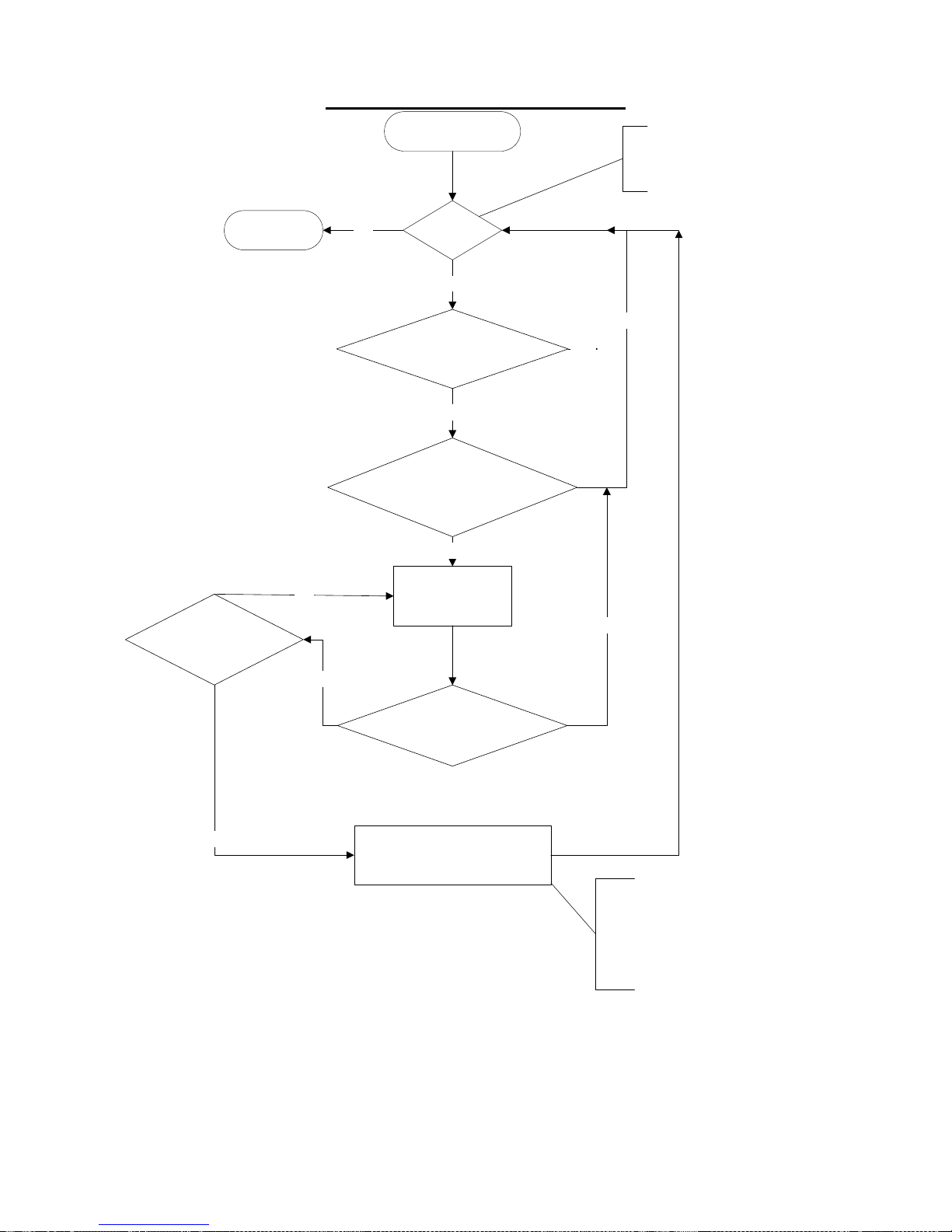
- 46 -
9a. Motion Alert flow chart:
EXIT
Motion Alert
NO
Enabled
YES
Movement/Vibration
detected
NO
No movement/Vibration
detected for more then
1 minute
YES
Can be enabled by
configuration setting,
SMS command or by
switch
NO
YES
Buzzer activate
for more then
30 seconds
YES
NO
NO
Sound Buzzer
Movement/Vibration
detected
Send Motion alert
message. Deactivate
motion alert enabled.
YES
The Motion alert can be enabled again
by SMS message, configuration menu
settings or by using the ‘Park’ switch
(if configured for motion alert). The
‘Park’ switch must be turned off and
turned on again to enable Motion alert
again.
46
Page 47
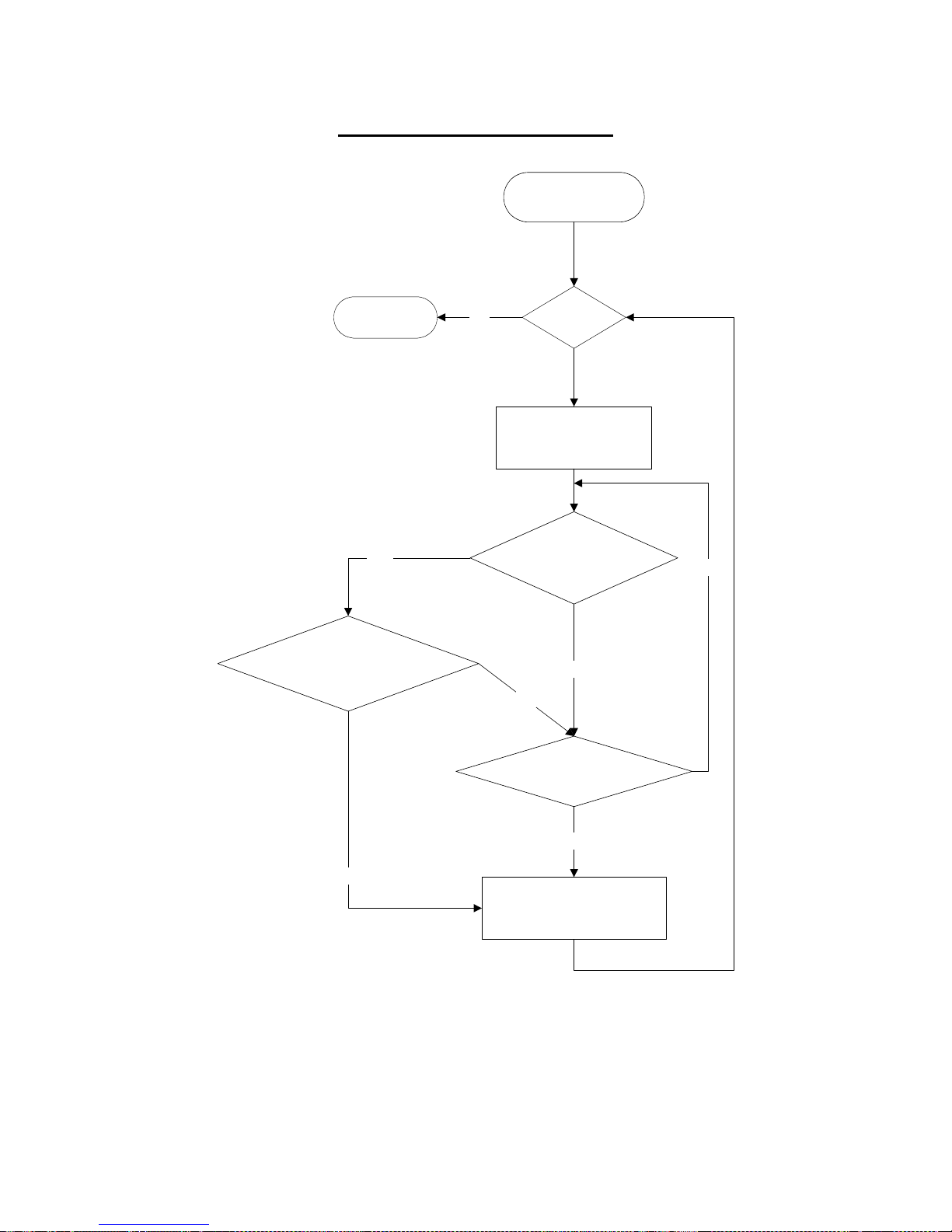
- 47 -
9c. Park Alert flow chart:
Park Function
NO
YES
EnabledEXIT
Delay 60 Seconds
Movement/Vibration
Detected
NO
More then 3 Times within 30
Seconds
YES
NO
NO
Speed more then 5km/h
YES
Activate Park Alarm.
Send Park alarm message.
47
Page 48

- 48 -
10. GPRS TESTING
Using the direct connection to the GSM modem (in test mode under ‘Hyperterminal).
1. Check GSM signal
AT+CSQ <Enter>
Example: +C S Q: 21,0
2. Check SIM card registered
AT+CREG?
Example: +CREG:0,1 (registered Home network)
3. Check network connected
AT+COPS?
Example: +COPS: 0,0,"CHINA MOBILE"
4. Set APN ( AT + CSTT )
AT + CSTT = “APN”[,”ID”, “password”]
Ex.
at + cstt = “internet” <Enter> (Chun Huw,TCC)
at + cstt = “FETNet01” <Enter> (FET)
5. Attach to GPRS network ( AT + CIICR )
AT + CIICR <Enter>
6. Get local IP address assign by GPRS Network(AT + CIFSR)
AT + CIFSR <Enter>
7. Start TCP/UDP connection ( AT+CIPSTART )
AT + CIPSTART = ”Mode”,”IP”,”Port”
Mode =TCP”or”UDP”
IP =remote server IP address
Port =remote server port
Example.
at + cipstart = “TCP”,”192.168.100.1”,”1234” <Enter>
8. DATA Send ( AT+CIPSEND )
AT + CIPSEND <Enter> (Send data out by Ctrl-z )
>DATA
Ctrl Z
AT + CIPSEND = <length> <Enter> (setup Length of data and send out automatically)
9. Close connection( AT + CIPCLOSE )
AT + CIPCLOSE <Enter>
10. Shut down connect ( AT + CIPSHUT )
AT+CIPSHUT<Enter>
48
Page 49
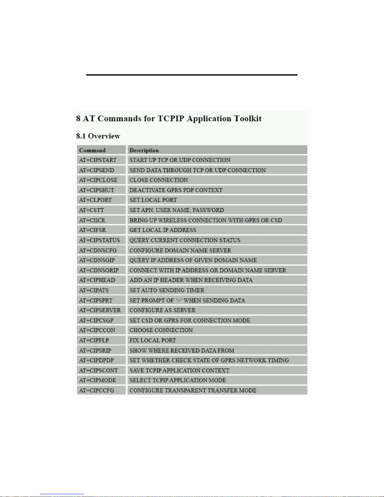
- 49 -
(Enter ‘at comstop’ to return to main menu)
11. AT COMMANDS FOR GPRS SUPPORT
Detailed Descriptions of commands
AT Commands For (TCP/UDP)
49
Page 50
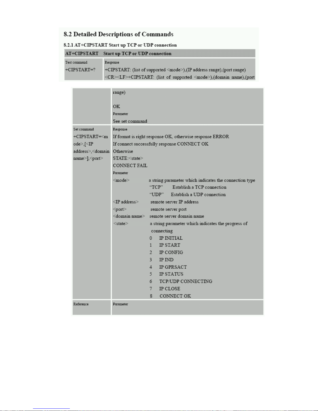
- 50 -
50
Page 51
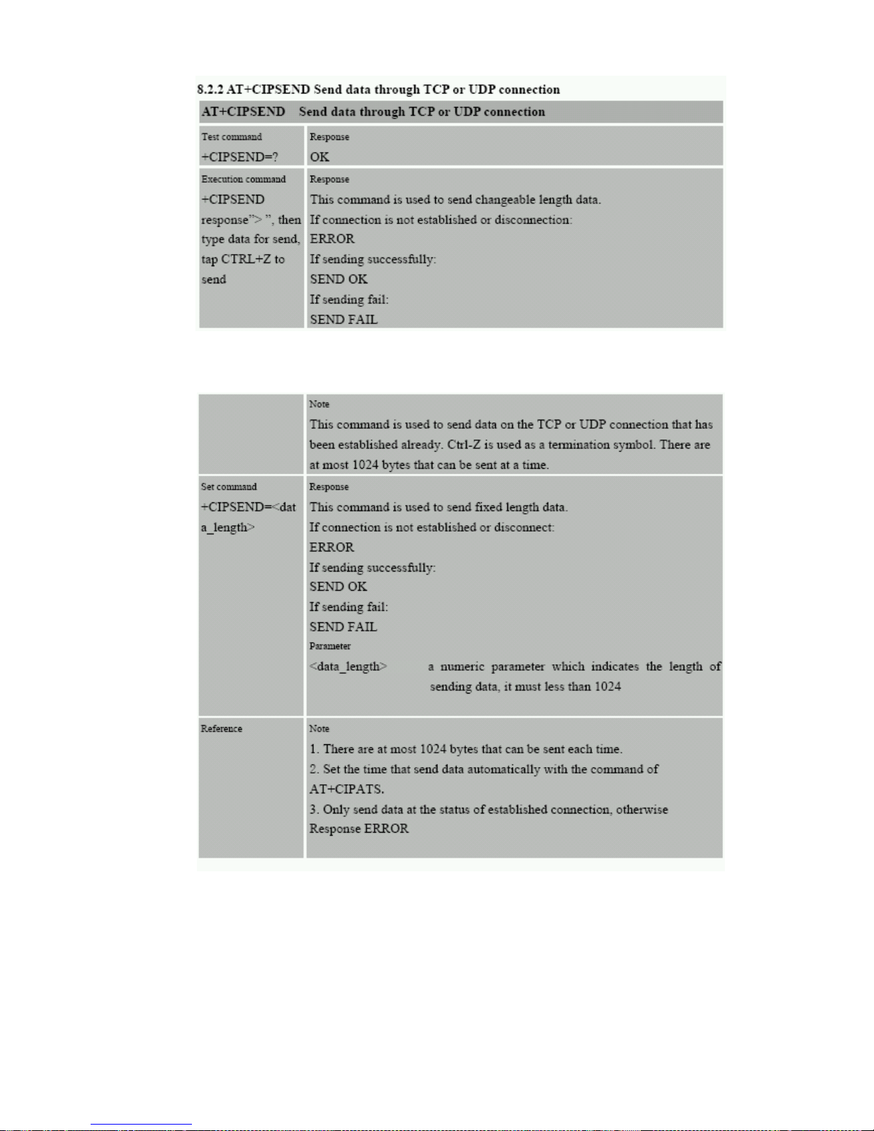
- 51 -
51
Page 52
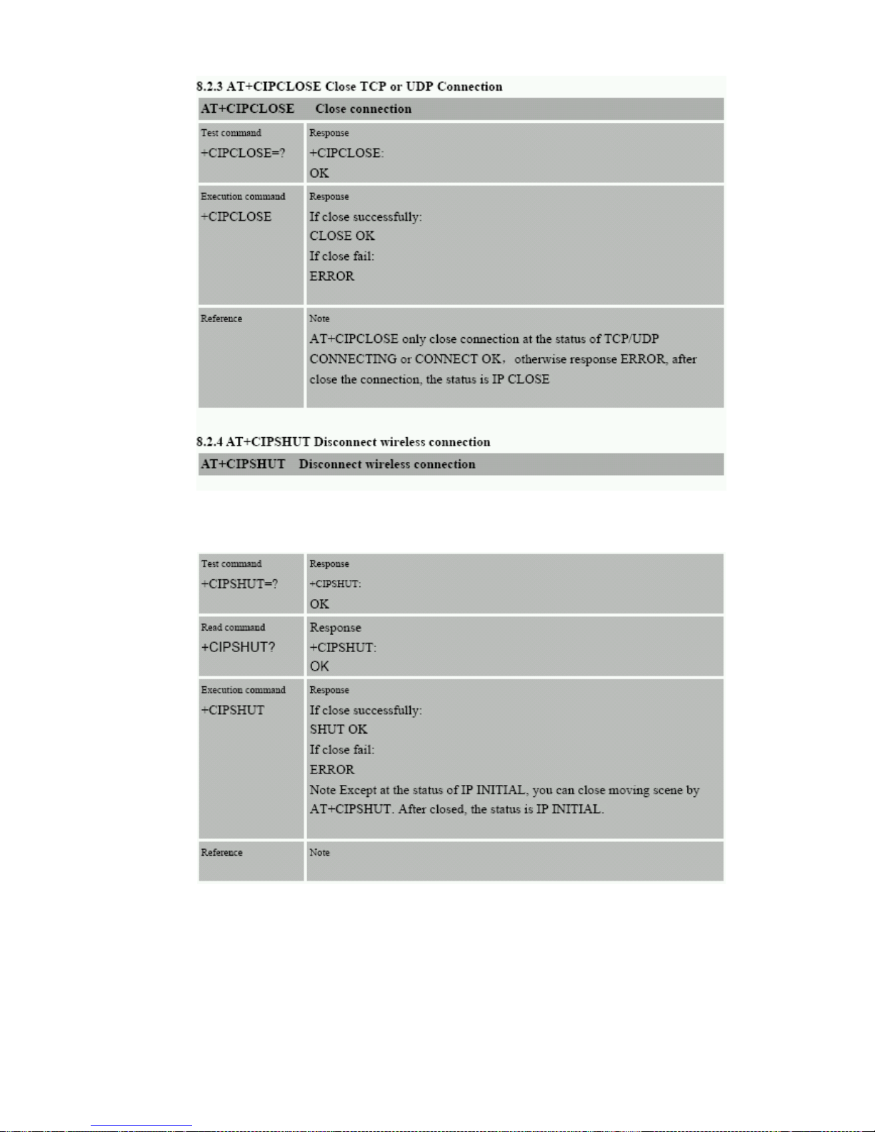
- 52 -
52
Page 53
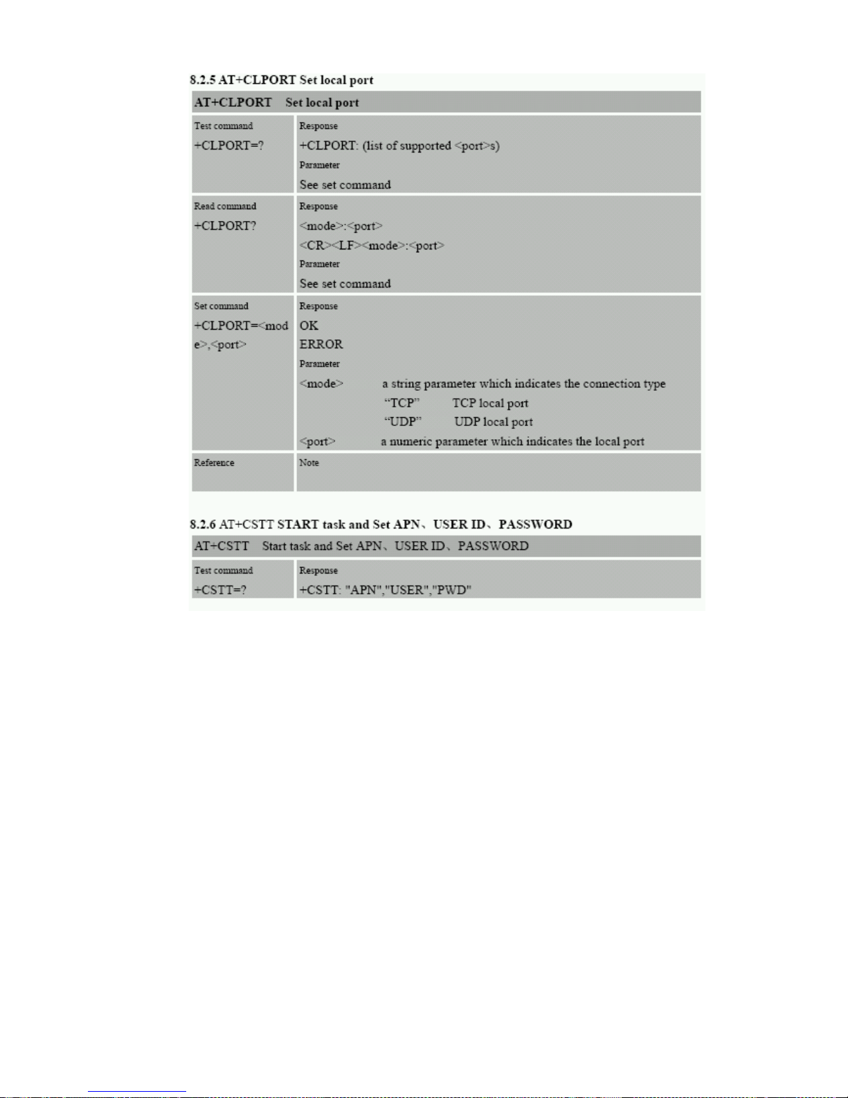
- 53 -
53
Page 54
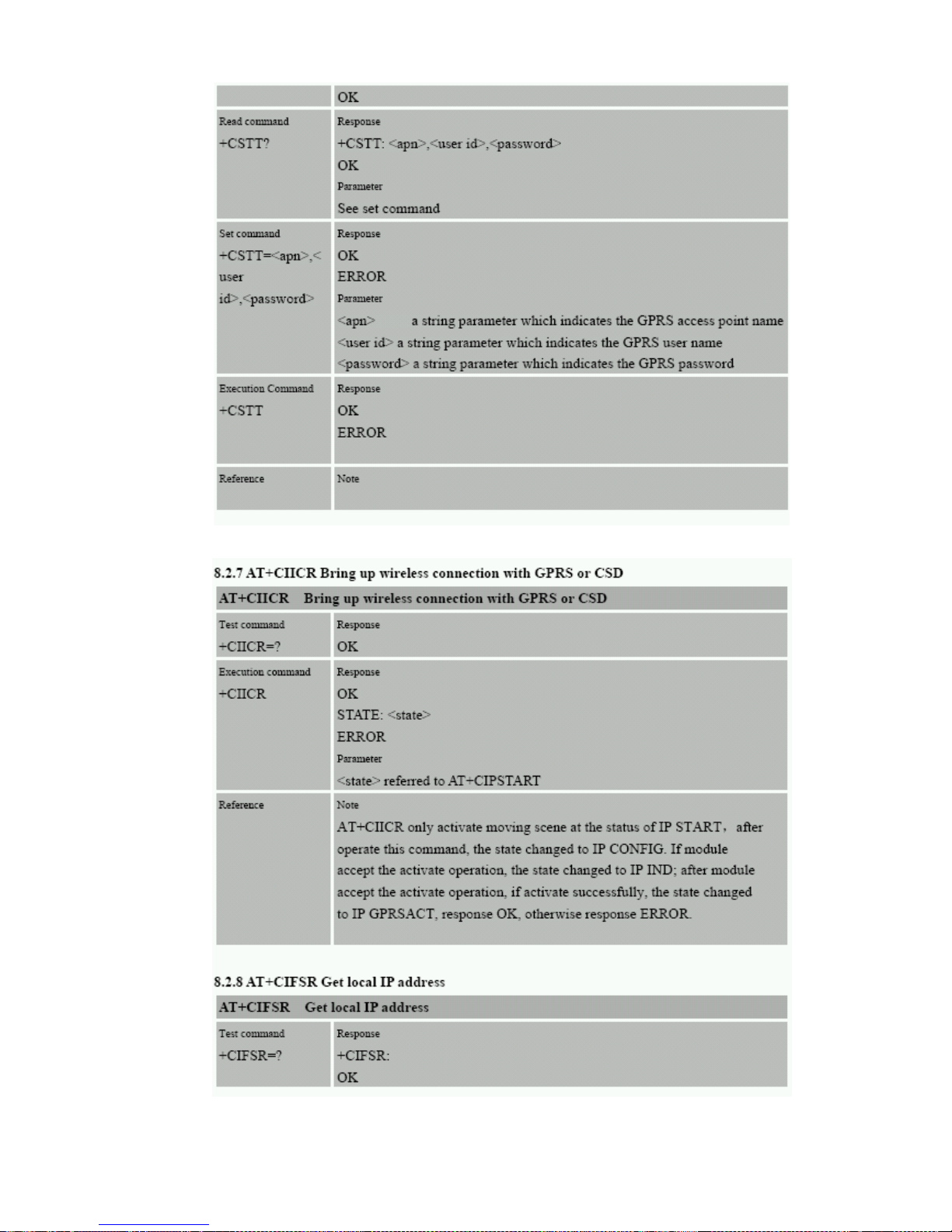
- 54 -
54
Page 55
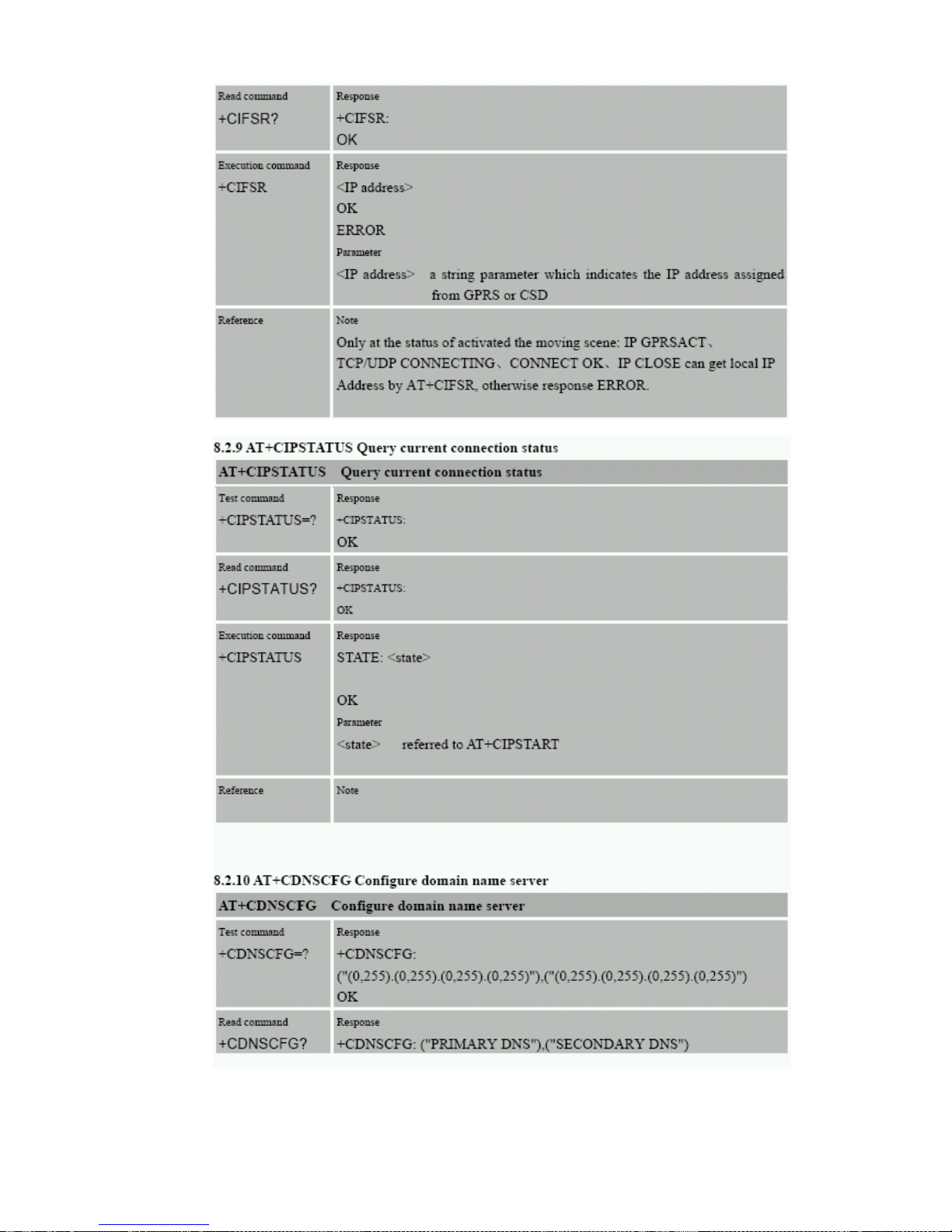
- 55 -
55
Page 56
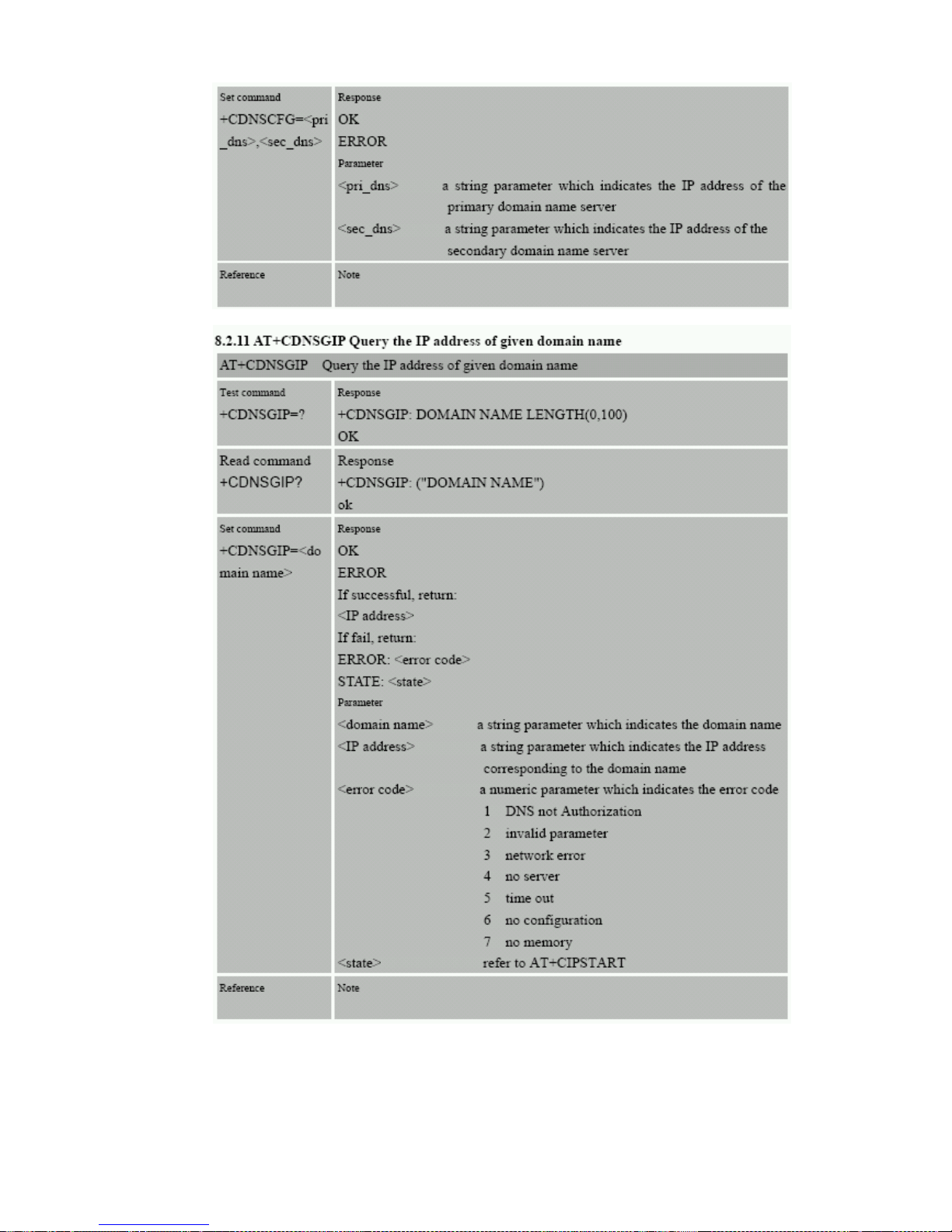
- 56 -
56
Page 57
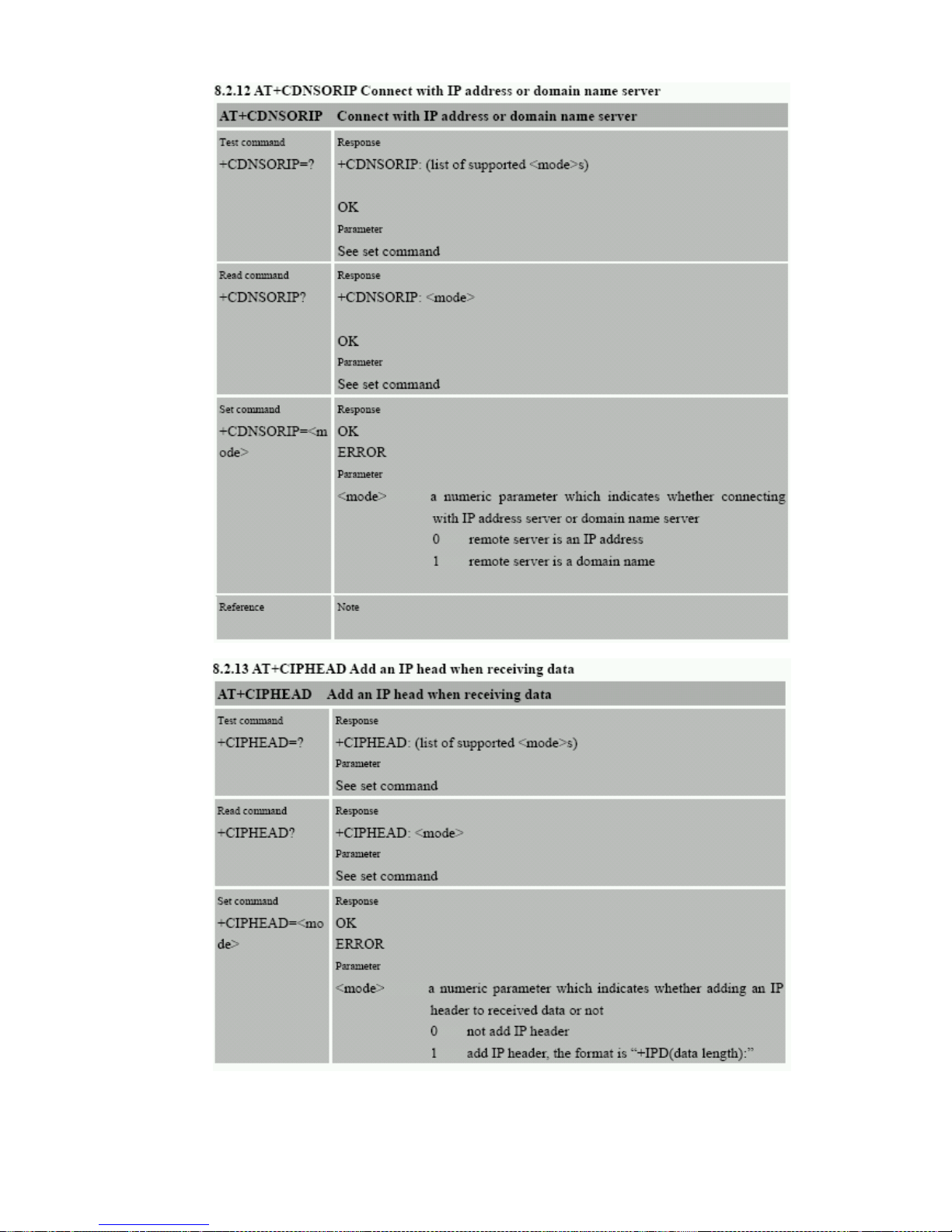
- 57 -
57
Page 58
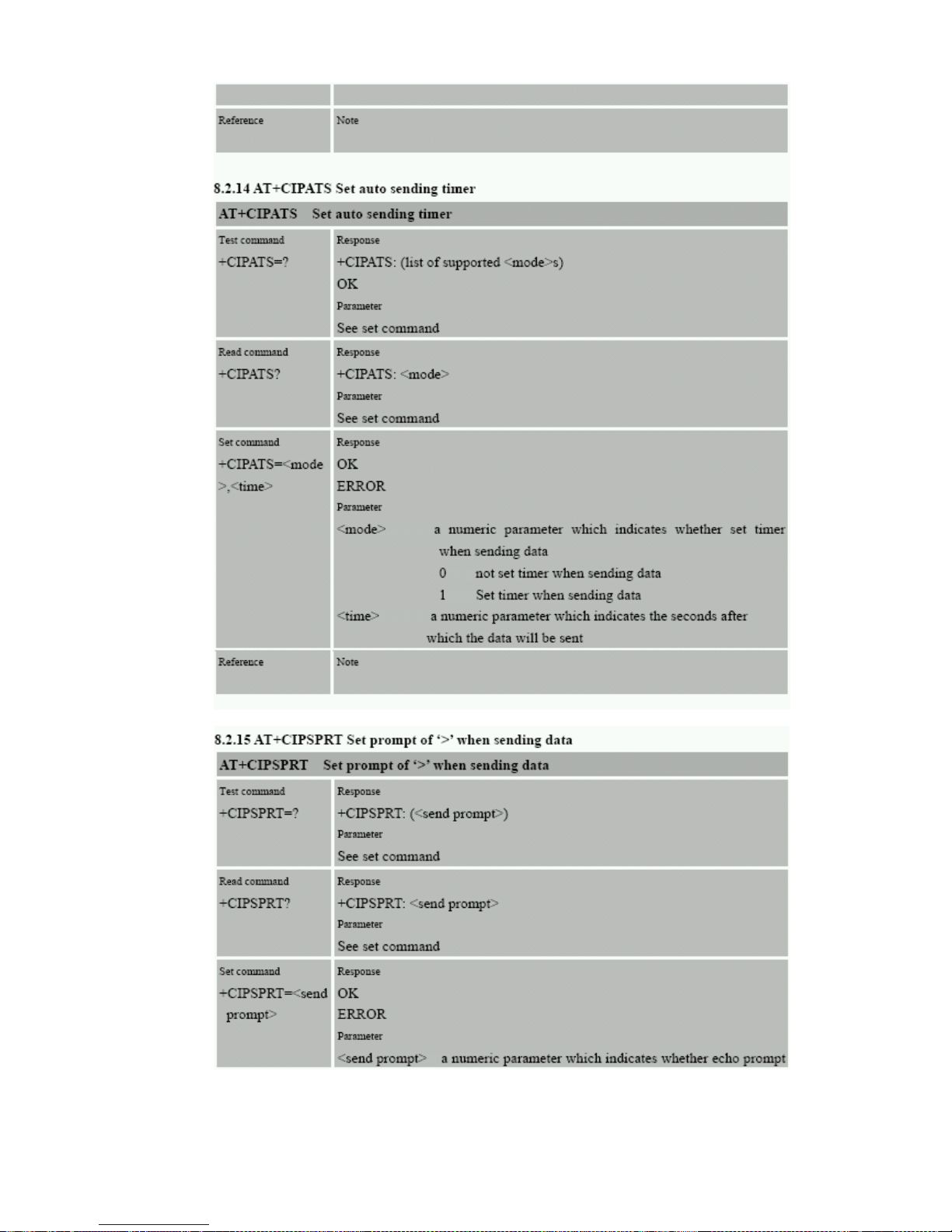
- 58 -
58
Page 59
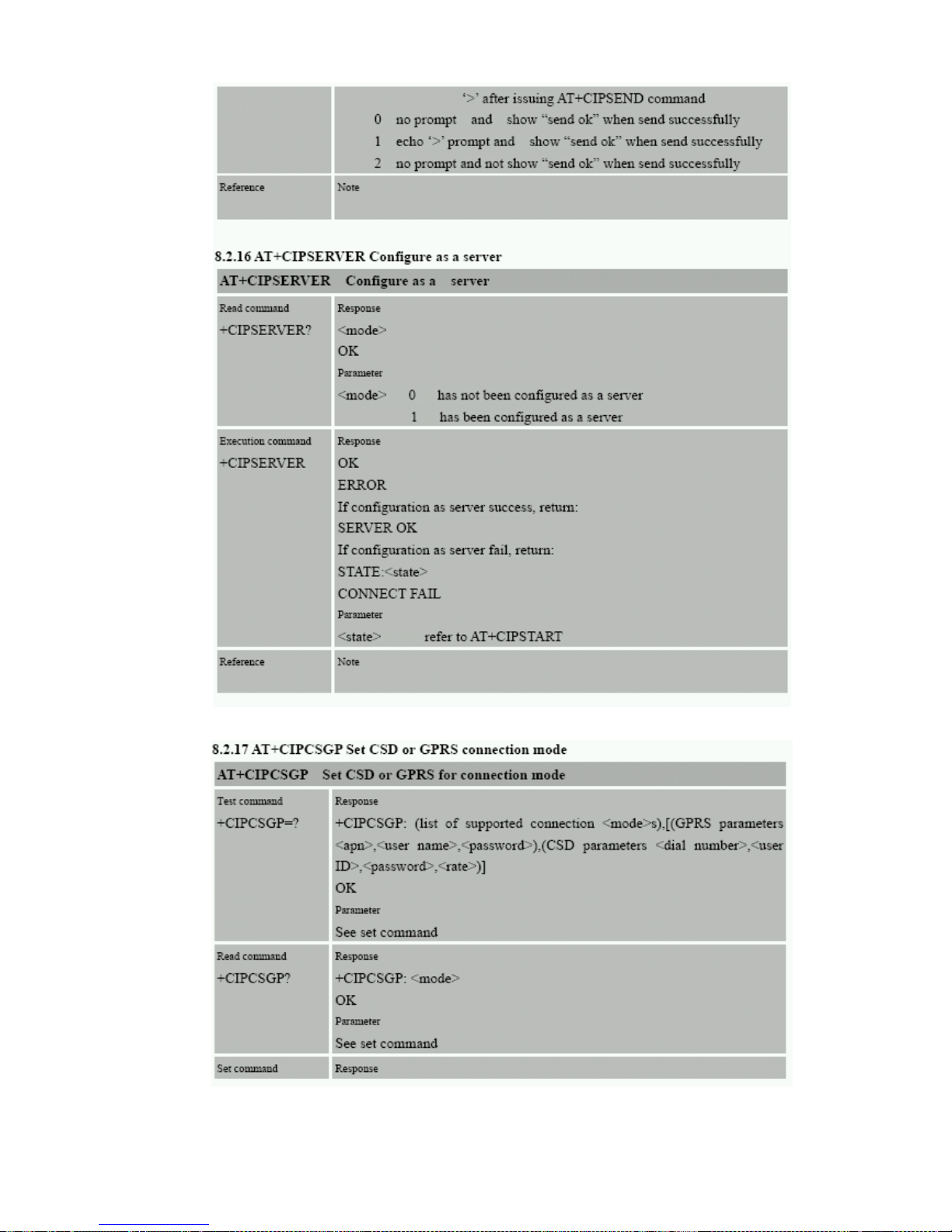
- 59 -
59
Page 60
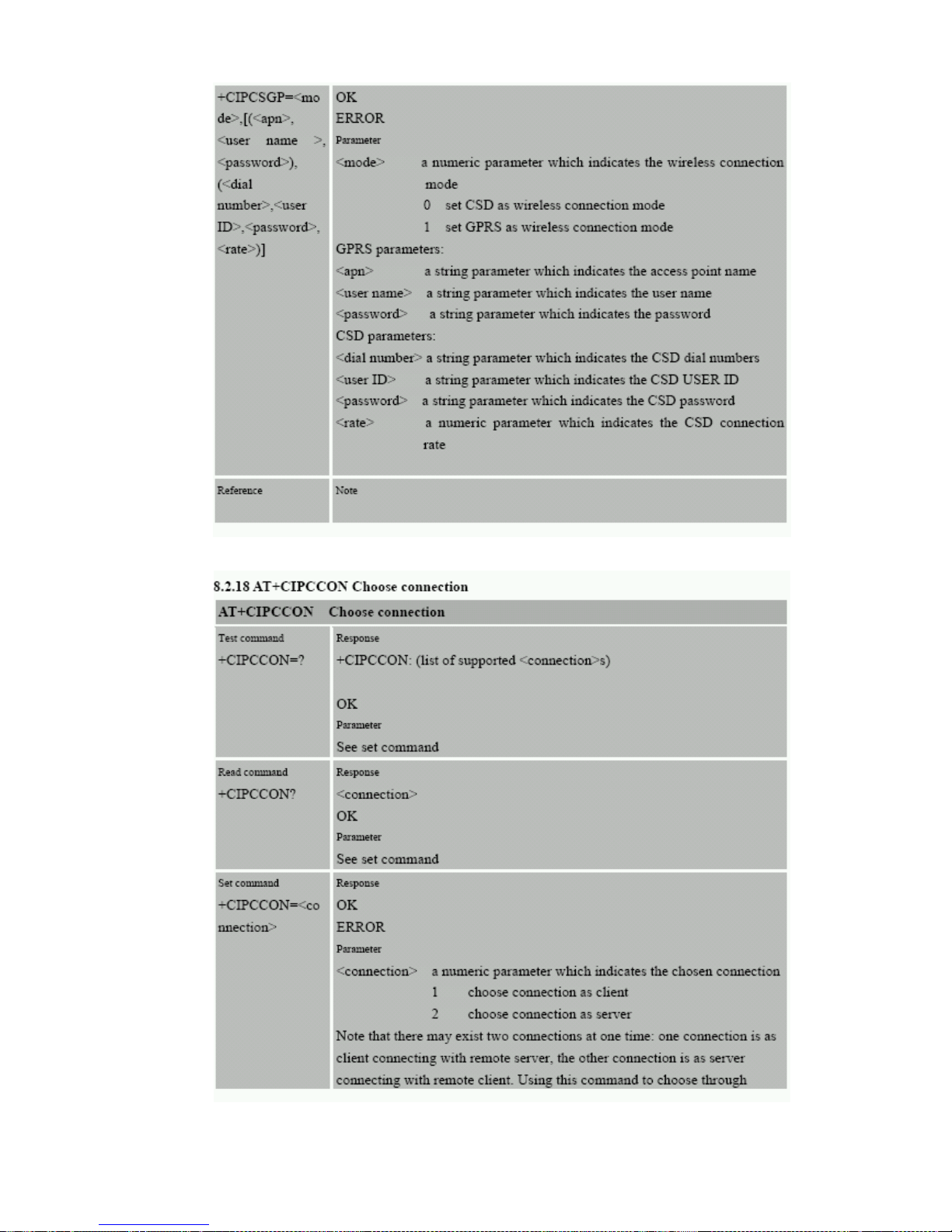
- 60 -
60
Page 61
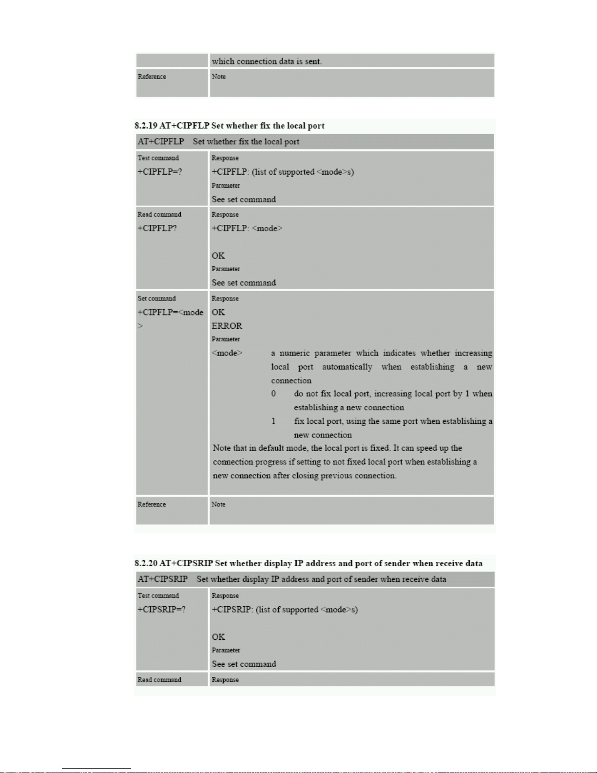
- 61 -
61
Page 62
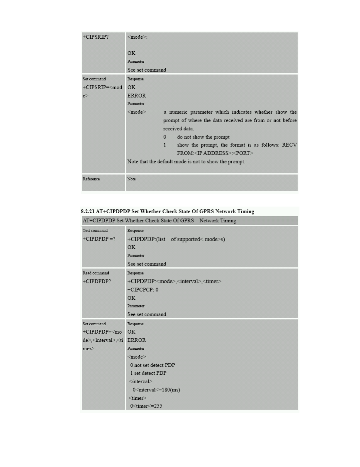
- 62 -
62
Page 63
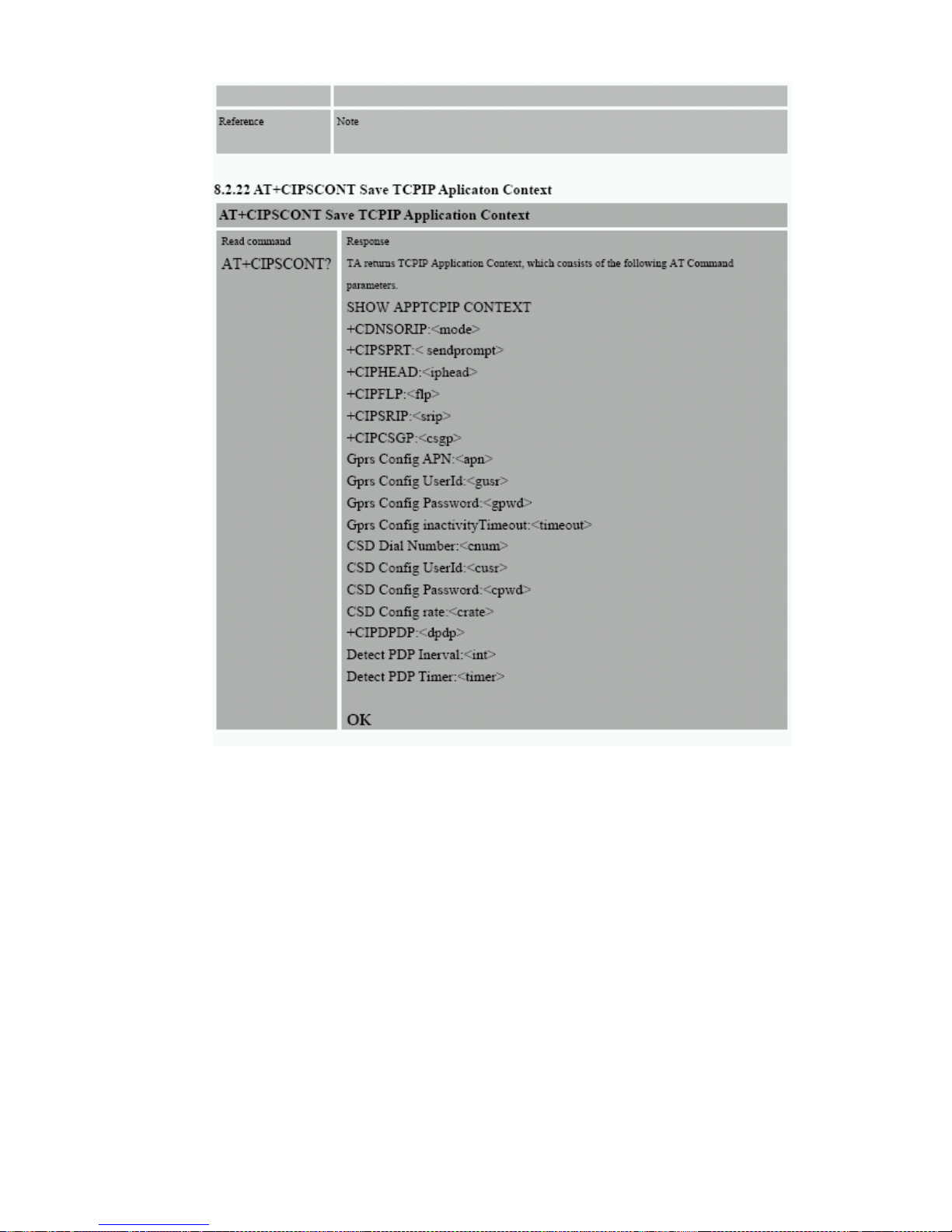
- 63 -
63
Page 64
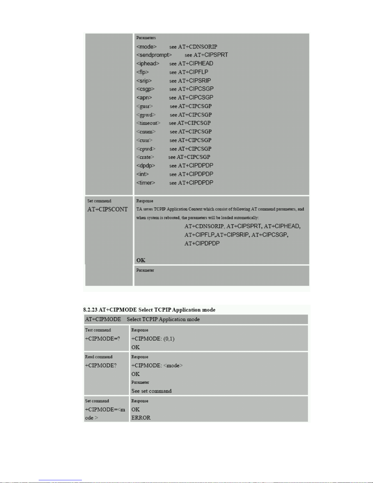
- 64 -
64
Page 65
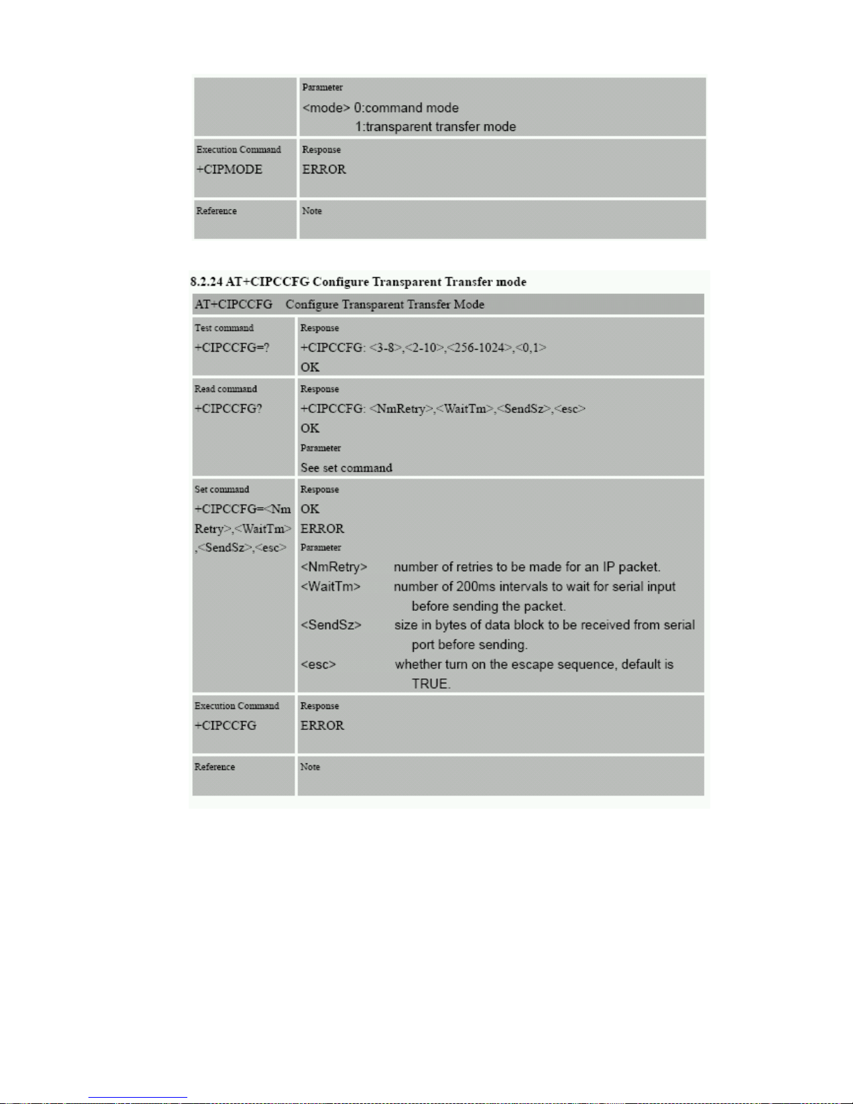
- 65 -
65
Page 66

- 66 -
12. Receiving and sending GPRS data:
The GPRS data format for sending is identical to the message format sent using SMS except that the GPRS
has a ‘header’ string at the start off the message. This is for all GPRS data including the ‘CONFIRM’ and
multiple location message.
The ‘header string’ is the IMEI number from the tracking unit GSM modem. The IMEI number is displayed on
the tracking unit or is shown when you exit the diagnostic main menu using ‘Hyperterminal’.
Sample data string received in GPRS mode (without compression):
<IMEI number>,05*850,000,PT35,A,2459.3640,N,12125.2958,E,000.0,224.8,00.8,07:47:26 09-0905,1.00,80,3F
Sample data string received in GPRS mode (with compression):
<IMEI number>,05*850000PT35A24593640N121252958E00002248008074726090905100803F
Any command message(s) can also be sent to the tracking unit in GPRS mode. The message(s) must be
sent within 2 seconds after any message is received in GPRS mode. The command messages as identical
to the messages sent using SMS.
GPRS errors:
The serial port will output GSM communication and any errors when connection or sending data in GPRS
mode.
66
Page 67
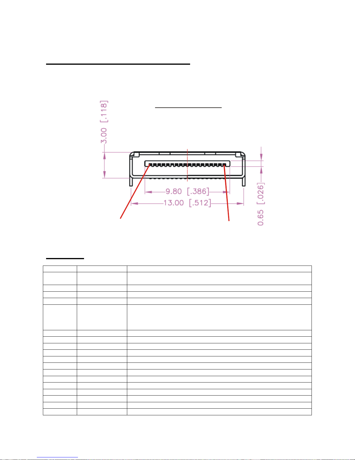
- 67 -
w
13. WTGAT Connections:
The WTGAT has one multi I/O connector to connect external devices. The user serial port and charger cable
will connect to this connector.
There are several other I/O pins that allow the WTGAT to be used for other applications.
Front Vie
Pin1
Pin18
Pin Out:
Pin Name Function
1 Vpp External input power. Must be between 4 and 4.7 Volt(Max) DC up to 1A.
* Internal battery must be removed!
2 Vcpu Power output 3.3Volt/DC – 50mA max (for ADC power)
3 Park Park switch. To activate connect to ground.
4 AUX1 Digital input AUX1 (Max +60Vdc). To activate connect to ground.
5 AUX2 Analo g input. This input is NOT protected so care must be taken before
using this input. Power input between 0 and 3.3VoltDC max. We
recommend to use Vcpu as power supply. Can be used to measure
temperature.
6 Loop1 Loop connection1 (See ‘Connecting the Wire loop cable’)
7 Loop2 Loop connection2 (See ‘Connecting the Wire loop cable’)
8 Panic Panic input. Connect to ground or loop2/loop1 to activate
9 Vin Battery charge input power. Must be +5Volt/ 500mA
10 Vin Battery charge input power. Must be +5Volt/ 500mA
11 Serial In Serial port input 9600 Baud
12 Serial Out Serial port output 9600 Baud
13 Speaker + External positive Speaker connection 8 Ohm /1.2 Watt max output
14 Speaker - External negative Speaker connection 8 Ohm /1.2 Watt max output
15 GND Ground
16 GND Ground
17 MIC - External negative microphone connection
18 MIC + External positive microphone connection
67
Page 68
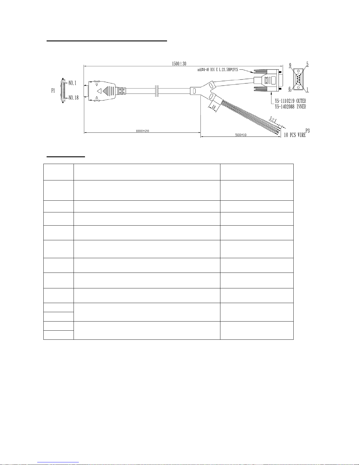
- 68 -
I/O cable pin out for WTGAT:
The picture below shows the WTGAT I/O cable.
.
Pin Out:
Pin Name Color
1
External input power
4~ 4.7 Volt(Max) DC / 1A.
2 Power output 3.3Volt DC – 50mA Max
3 Park switch
4 Digital input AUX1 (Max +60Vdc)
5
Analog input or Digital output 0 ~3.3Volt
DC only
6 Loop1
7 Loop2
8 Panic input
9
10
15
16
Battery charge input power+5Volt/ 1A
Ground
Black
Brown
Red
Orange
Yellow
Green
Blue
Purple
Grey
White
68
Page 69
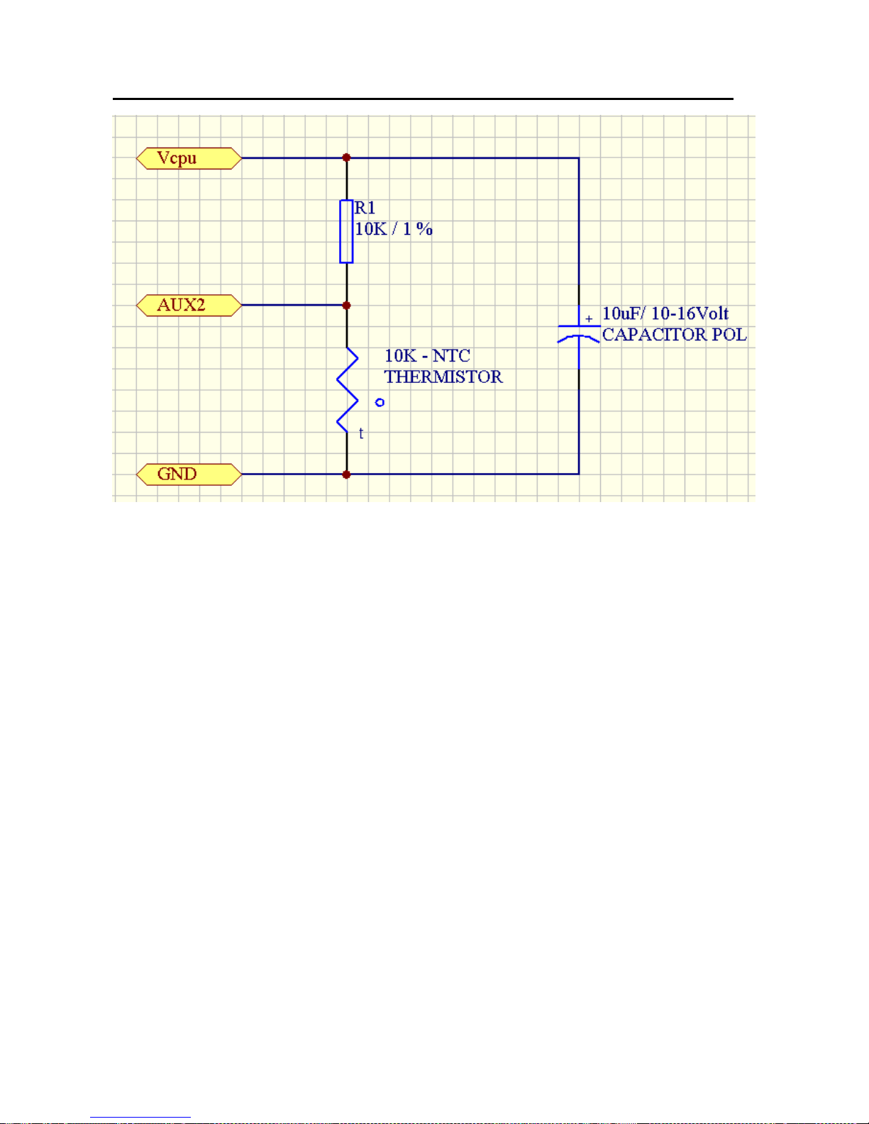
- 69 -
Measuring temperature (NTC) using the AUX2 input example:
The AUX2 input voltage (yellow wire) will change when the temperature changes. Most Thermistors are at
normal resistance (in above example we use 10 K) at 25 degrees. So in our example that will be 10K.
The input voltage to AUX2 will then be 1.27 Volt (ADC value will be 128 decimal or 80 hex).
The input voltage is always included in the ‘location message’ and can be configured to activate below or
above set value. Using the WTGAT I/O cable the AUX2 input must be connected to the yellow wire, the GND
to the white wire and the Vcpu to the Brown wire.
69
Page 70
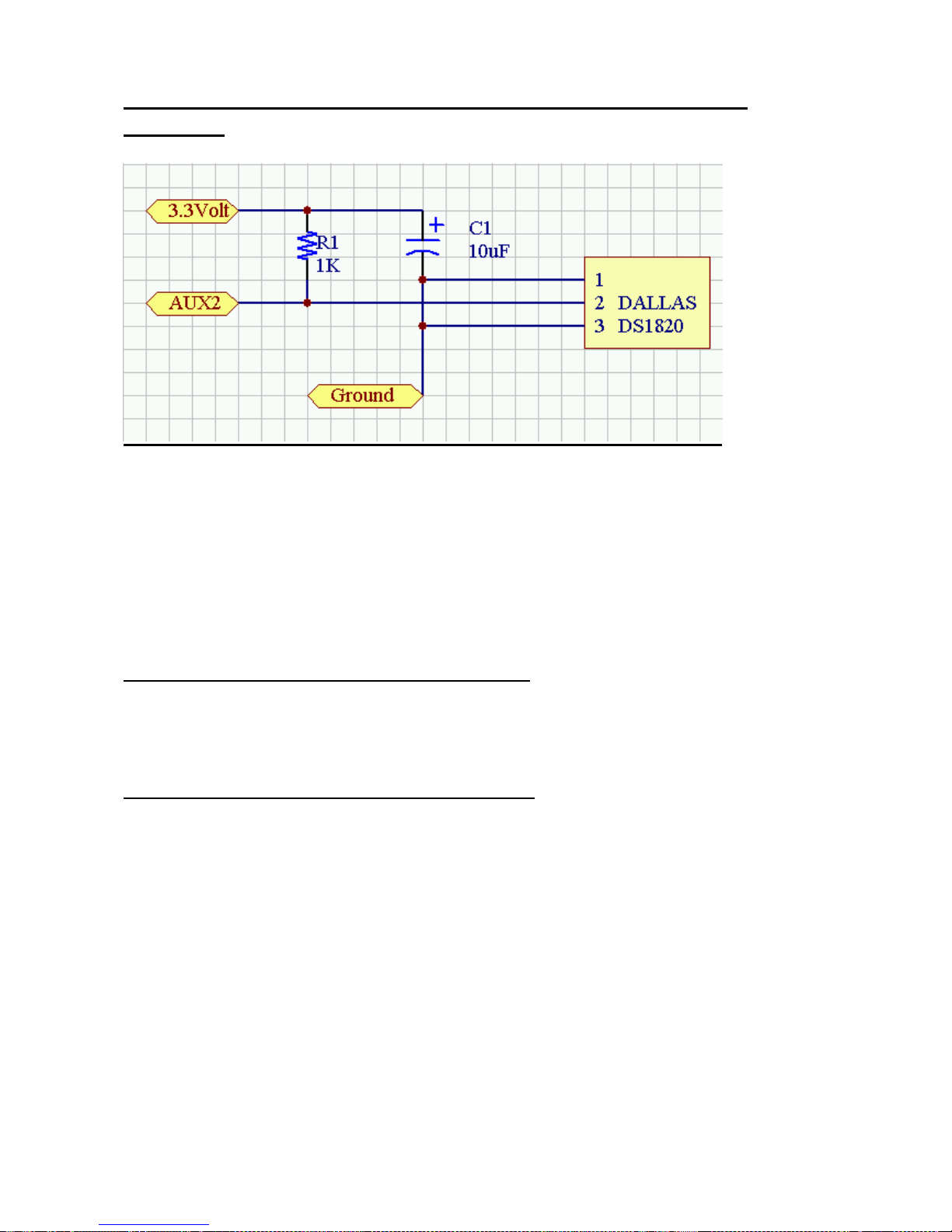
- 70 -
Measuring temperature (DS18S20) using the AUX2 input
example:
When the DS18S20 is connected as shown above and enabled in the configuration menu program the
temperature measured is automatic included in every location message.
The WTGAT will measure the temperature when running in normal running mode every few seconds.
When the temperature trigger is activated a location message will be send with the temperature measured
and the activation status. The temperature trigger will deactivate once the temperature goes back and stay
between the low and high trigger value and automatic reactivate again once the temperature goes again
below or above the trigger value configured.
During sleep mode no temperature measurement will be done and cannot activate in sleep mode.
Please note that the battery consumption will be more then using the DS18S20 to measure the temperature.
Measures temperatures from –55°C to +125°C (–67°F to +257°F) +/- 0.5 degree accurate
Example location message data with positive temperature:
05*850,
Shows temperature trigger activated with temperature at 36 (HEX). The temperature value needs to be
converted depending on positive or negative value. In the above sample the temperature is positive (status
code digit 3 is zero and the temperature is 36 hex = 54/2 = 27 degrees
Example location message data with negative temperature:
05*850,
Shows temperature trigger activated with temperature at CE (HEX). The temperature value needs to be
converted depending on positive or negative value. In the above sample the temperature is negative (status
code digit 3 is 8 and the temperature is CE hex = 206 -> (206 – 256)/2 = - 25 degrees
Testing the DS18S20 connection can be done when the WTGAT enters ‘normal running mode’ (when you
exit the diagnostic mode using Hyper terminal). When pressing the ‘T’ or ‘t’ key the WTGAT will display the
temperature m e as ured by the DS18S 20 . Th e DS 18 S 2 0 t em perature tes t will exit automat i c after 60 seconds
or when you press the ‘Q’ or ‘q’ key.
THE CORRECT TEMPERATURE FOR ZERO (00) to MAX 99 DEGREES. This is only limited for the
testing option. Temperature shown in the location message can be from –55 to +125 Degrees.
The complete datasheets for DS18S20 can be downloaded from the ‘maxim’ web site (http://www.maximic.com/).
@00,PT35,A,2459.3640,N,12125.2958,E,000.0,224.8,00.8,07:47:26 09-09-05,1.00,80,36
@08,PT35,A,2459.3640,N,12125.2958,E,000.0,224.8,00.8,07:47:26 09-09-05,1.00,80,CE
PLEASE NOTE THAT THE TESTING OPTION CAN ONLY DISPLAY
Using the WTGAT I/O cable the AUX2 input must be connected to the yellow wire, the GROUND to the white
wire and the 3.3Volt to the Brown wire. The cable length is limited to 2 meters max.
70
Page 71
- 71 -
Connecting the wire loop cable:
The WTGAT has option to connect external wire. When the wire is cut the WTGAT will automatic power up.
This function will activate and work in any sleep mode configured.
The wire connection must be connected as shown here:
PT35 Connector
Loop1
Wire Loop
Loop2
Panic
Connect at connector
Please Note:
If the wire loop is cut the WTGAT will power up (if not already powered up) and sent Panic activation
message. Once the wire is cut the WTGAT will not power down again. The wire must be restored or
connection between Panic, loop2 and loop1 disconnected.
working in ‘normal’ running mode or 3+ seconds when in sleep mode). For correct working the wire
look cable must not be connected to any other cable or have any open wire that can be touched by
hand.
For normal Panic activation there is no need to connect the wire loop cable. The Panic input will activate if
connected (by push button) t o GND. If the WTGAT I/O cable is used then the Panic input is activated when
the ‘Purple’ and ‘White’ wire is connected for more then 1 second.
(The wire must be open for 1+ second when
71
Page 72

- 72 -
14. Technical Specifications
Description:
Hardware F eatures:
* The GPS and GSM modules are integrated inside the tracking unit case.
* GPRS/ SMS and Voice I/O
* Up to 5.000 location / activation messages can be saved (automatic)
* Built in motion switch
* Battery charge circuit to charge 3.7 Volt Li-ion battery
* Panic input button (will power up the unit from deep sleep mode)
* Park Switch
* Super low battery use in deep sleep mode (low power timer on)
(Up to 3 years
* Timer circuit can wake up unit by time (hours – minutes – seconds – days Months) or any configured time
or date.
* Time backup battery will last up to 5+ years without battery or external power connected.
* 18 Pin mini multi I/O connector
* One digital input (0 to 60VDC)
* One analogue input (3.3VDC Max) or Digital Output (0-3.3Volt)
(Can be selected as Input or Output using the setup configuration menu)
* External battery backup option (to connect second battery or Solar panel option)
* USB to Serial (Serial RS232 port (9600 baud Rate)) for external communication, firmware upgrade or direct
access to modem (9600 baud rate).
* Build in Amplified Speaker (1.25Watt output power) and Microphone
* Build in Active high performance GPS antenna
* Unit can be activated from deep sleep mode using Panic input, wire connection (will activate the unit when
wire is broken or cut) or when closed loop is opened.
* Low battery led indicator
* Status and GPS led indicator
* Build in buzzer for warning and motion detection
* External option to connect Speaker and Mic
* Operating temperature range -25 deg. C to +70 deg. C (Battery 0 – +60 Degrees C.)
* This assumes that the battery has negligible self-discharge
Physical Characteristics:
Unit size: LxWxH 90.4x 38.4 x 15.1 mm (18.25 max)
Plastic / Waterproof if required
Case Environmental Characteristics:
Operational Temperature: - 25 ~ + 70 °C (board temperature)
Storage temperature -40°C to +80°C
1 Multi I/O connector (18 pin with locking pins)
1 On/Off switch / 1 Park switch / 1 Panic button
Electrical Characteristics:
Input Voltage: + 5 Volt DC regulated (USB port power)
Power Consumption: Depending on operating mode between 10- hours and 3 years
battery).
GPS Specifications:
(*) with 3.7V/800mA battery)
(*) (when using 800mA
72
Page 73

- 73 -
uBlox- LEA-5S chipset version
Receiver Performance Data
Receiver Type
50-channel u-blox 5 engine
GPS L1 C/A code
GALILEO L1 Open Service (with upgrade)
SBAS: WAAS, EGNOS, MSAS, GAGAN
Max. Update Rate 4 Hz
Accuracy1 Position 2.5 m CEP SBAS 2.0 m CEP
Acquisition (Open sky, stationary requirements)
Cold starts: 29 s (Open Sky) – Can be between 1-3 minutes or more
Warm starts: 29 s
Aided starts2: <1 s
Hot starts: <1 s
Sensitivity
Tracking: - 160 dBm
Reacquisition: - 160 dBm
Cold starts: - 144 dBm
Operatl. Limits
Velocity: 515 m/s (1000 knots)
Operating Temp.
-40°C to 85°C
Storage Temp.
-40°C to 85°C
Powered by the 50-channel u-blox 5 positioning engine, the module boasts a Time-To-First-Fix of under 1
second. The dedicated acquisition engine, with over 1 million correlators, is capable of massive parallel
time/frequency space searches, enabling it to find satellites instantly. Innovative design and technology
suppresses jamming sources and mitigates multipath effects, giving u-blox 5 GPS receivers excellent
navigation performance e ven in the most challenging environments.
GSM Modem Specifications:
Power supply Single supply voltage 3.4V – 4.5V
Power saving Typical power consumption in SLEEP mode to 3mA
Quad-band: 900, DCS 1800, PCS 1900,EGSM 850, DCS 1800, PCS 1900
Compliant to GSM Phase 2/2+
GSM class Small MS
Transmit po wer Class 4 (2W) at EGSM900
Class 1 (1W) at DCS1800 and PCS 1900
GPRS connectivity
GPRS multi-slot class 10
GPRS mobile station class B
Build in TCP/IP support.
73
Page 74

- 74 -
Temperature range
Operation: -25°C to +70°C
Storage temperature -40°C to +80°C
DATA
GPRS:
CSD:
GPRS data downlink transfer: max. 85.6 kbps
GPRS data uplink transfer: max. 42.8 kbps
Coding scheme: CS-1, CS-2, CS-3 and CS-4
Supports the protocols PAP (Password Authentication
Protocol) usually used for PPP connections.
Integrated TCP/IP protocol.
Support Packet Switched Broadcast Control Channel (PBCCH)
CSD transmission rates: 2.4, 4.8, 9.6, 14.4 kbps, non-transparent
Unstructured Supplementary Services Data (USSD) support
SMS, MT, MO, CB, Text and PDU mode
SMS storage: SIM card
Support transmission of SMS alternatively over CSD or GPRS.
User can choose preferred mode.
FAX Group 3 Class 1
SIM interface Supported SIM card: 1.8V ,3V
Audio features Speech codec modes:
Half Rate (ETS 06.20)
Full Rate (ETS 06.10)
Enhanced Full Rate (ETS 06.50 / 06.60 / 06.80)
Echo cancellation
Noise reduction
Phonebook management Supported phonebook types: SM, FD, LD, MC, RC, ON,
ME,BN,VM,LA,DC,SD
Application Toolkit Supports SAT class 3, GSM 11.14 Release 98
Real time clock Implemented
Timer function Programmable via AT command
Firmware upgrade Firmware upgradeable over serial interface
Coding schemes and maximum net data rates over air interface
Coding scheme 1 Timeslot 2 Timeslot 4 Timeslot
CS-1: 9.05kbps 18.1kbps 36.2kbps
CS-2: 13.4kbps 26.8kbps 53.6kbps
CS-3: 15.6kbps 31.2kbps 62.4kbps
CS-4: 21.4kbps 42.8kbps 85.6kbps
GPS/ GSM Antenna Specifications:
Build into the unit.
Power use :
Using 800mA/ 3.7Volt battery.
The WTGAT has 3 different working modes. Depending on configuration settings power consumption will be
as shown here.
1. Normal running mode:
GSM on – GPS on -Timer – running – Panic – Digital input – ADC input on
Will last 10 Hours.
No movement and inputs activated for 5 minutes then:
74
Page 75

- 75 -
GSM on – GPS off -Timer – running – Panic – Digital input – ADC input off
(No activation last 4 to 11 Days – Depending on GSM provider refresh rate)
2. Basic sleep mode:
GSM on – GPS on -Timer – running – Panic – Digital input – ADC input on
Will last 10 Hours.
No movement and inputs activated for 5 minutes then:
GSM off – GPS off -Timer – running – Panic – Digital input – ADC input off
Will last up to 55+ days
3. Deep sleep mode:
GSM on – GPS on -Timer – running – Panic – Digital input – ADC input on
Will last 10 Hours.
No movement and inputs activated for 5 minutes then:
GSM off – GPS off -Timer – running – Panic – or wire loop connected
Will last up to 3-5+ years
* This assumes that the battery has negligible self-discharge
Possible applications:
- Security tracking
- Containers or Boats where no external power connection is available
- Remote locations
- Older people
- Dog tracking
(*).
(*)
15. Federal Communications Commission (FCC) Statement
You are cautioned that changes or modifications not expressly approved by the part
responsible for compliance could void the user’s authority to operate the
equipment.
Federal Communications Commission (FCC) Statement
This equipment has been tested and found to comply with the limits for a Class B digital
device, pursuant to part 15 of the FCC rules. These limits are designed to provide
reasonable protection against harmful interference in a residential installation. This
equipment generates, uses and can radiate radio frequency energy and, if not installed
and used in accordance with the instructions, may cause harmful interference to radio
communications. However, there is no guarantee that interference will not occur in a
particular installation. If this equipment does cause harmful interference to radio or
television reception, which can be determined by turning the equipment off and on, the
75
Page 76

- 76 -
user is encouraged to try to correct the interference by one or more of the following
measures:
-Reorient or relocate the receiving antenna.
-Increase the separation between the equipment and receiver.
-Connect the equipment into an outlet on a circuit different from that to which the receiver
is connected.
-Consult the dealer or an experienced radio/TV technician for help.
You are cautioned that changes or modifications not expressly approved by the party
responsible for compliance could void your authority to operate the equipment.
Operation is subject to the following two conditions:
1) this device may not cause interference and
2) this device must accept any interference, including interference that may cause
undesired operation of the device.
FCC RF Radiation Exposure Statement:
1. This Transmitter must not be co-located or operating in conjunction with any other
antenna or transmitter .
2. This equipment complies with FCC RF radiation exposure limits set forth for an
uncontrolled environment. This equipment should be installed and operated with a
minimum distance of 20 centimeters between the radiator and your body.
Updated 16-4-2009
76
 Loading...