

Page 1

Syncbox
GPS Time Server
User Manual
Version 2.1
Page 2

Syncbox - GPS Time Server - User Manual - Version 2.1II
SAFETY PRECAUTIONS
To reduce the risk of re, or electric shock, DO NOT allow the
Syncbox to be exposed to rain or moisture.
To avoid the risk of electric shock, DO NOT open the enclosure.
To prevent damage to the unit, clean ONLY with a dry cloth.
Use this product ONLY with the supplied power adapter. If the
power adapter becomes damaged, consult a qualied electrician
for advice.
The supplied power adapter is intended to serve as a disconnect
device. The socket-outlet should be installed near the equipment
and should be easily accessible.
CERTIFICATION
In accordance with European Directives 2006/95/EC (The Low
Voltage Directive) and 2004/108/EC (The Electromagnetic
Compatibility Directive), the Syncbox is in conformity with the
applicable requirements of BS EN 60950-1:2006 (Information
Technology Equipment - Safety), BS EN 55022:2006 (Information
Technology Equipment - Radio disturbance characteristics - class
B) and BS EN 55024:2003 (Information Technology Equipment Immunity characteristics).
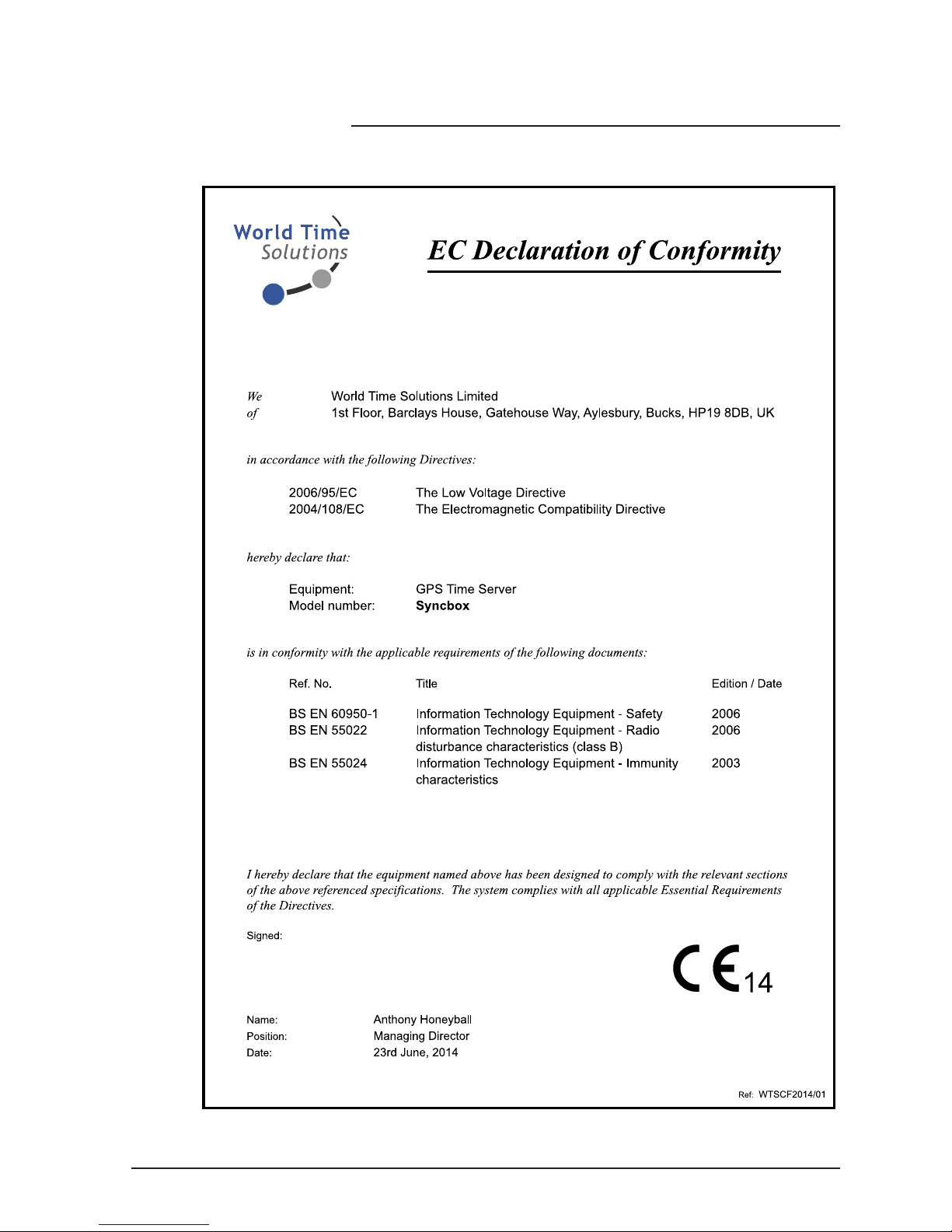
A copy of the EC Declaration of Conformity is included at the rear
of this user manual. Copies of the original document may be
downloaded from our web site at:
www. wo rl dt imeso lu ti ons.com
RoHS COMPLIANCE
World Time Solutions Limited works with it’s suppliers to ensure
all products comply with the Restriction of Hazardous Substances
(RoHS) directive.
For further information, please visit our web site at:
www. wo rl dt imeso lu ti ons.com /r oh s.htm l
DISPOSAL
Please dispose of this unit properly. To minimize pollution and
help protect the environment, this unit should be recycled.
For further information and/or to view a copy of the World Time
Solutions Limited Waste Electrical and Electronic Equipment
Policy, please visit our web site at:
www. wo rl dt imeso lu ti ons.com /r ec ycle. ht ml
COPYRIGHT
© 2014 - 2017 World Time Solutions Limited. All Rights Reserved.
All information contained within this document is the property of
World Time Solutions Limited and cannot be used or reproduced
by any person or company without written consent from World
Time Solutions Limited.
World Time Solutions Limited reserves the right to make periodic
amendments to the information in this document without notice.
TRADEMARKS
Microsoft, Windows, Windows XP, Vista and Windows 7 are either
registered trademarks or trademarks of Microsoft Corporation in
the United States and other countries.
All other registered trademarks and trademarks are property of
their respective owners.
SOFTWARE LICENCE
This product contains proprietary World Time Solutions Limited
software. This proprietary World Time Solutions Limited software
is supplied under the World Time Solutions Limited Software
Licence Agreement.
To obtain further information and/or a copy of the software licence
please visit:
www. wo rl dt imeso lu ti ons.com
LIMITED WARRANTY
The Syncbox GPS Time Server is guaranteed against failure due
to faulty parts or workmanship for a period of ve (5) years from
date of purchase.
In the event of product failure due to faulty parts or workmanship
within the warranty period, World Time Solutions Limited, at
its own discretion, will either (a) repair the product, (b) supply
a replacement product, (c) supply a functionally equivalent
replacement product, or (d) refund the purchase price of the
product.
The limited warranty will not apply if (a) the product has not been
installed or operated as per our instructions, (b) the product has
been modied in anyway.
In the event of failure, the Syncbox should be returned to the
manufacturer for inspection and repair. Please visit our support
pages for further details:
www. wo rl dt imeso lu ti ons.com /s up port. ht ml
TECHNICAL SUPPORT
To obtain help with the installation or operation of the Syncbox,
please visit our web site at:
www. wo rl dt imeso lu ti ons.com /s up port. ht ml
Page 3

IIISyncbox - GPS Time Server - User Manual - Version 2.1
Contents
1 - Introduction ....................................................................................................................1
1.1 - Quick start guide ...................................................................................................................... 1
1.2 - What’s in the box? ...................................................................................................................1
1.3 - Getting to know your Syncbox ................................................................................................. 2
1.4 - The status LED ........................................................................................................................ 3
2 - Installing your Syncbox ................................................................................................. 4
2.1 - Physical installation ................................................................................................................. 4
2.2 - Connecting and installing the GPS antenna ............................................................................ 4
2.3 - Power connection ....................................................................................................................4
2.4 - USB setup port ........................................................................................................................ 4
2.5 - Ethernet port (version dependent) ........................................................................................... 5
2.6 - RS-232/RS-485 output (version dependent) ........................................................................... 5
3 - Syncbox Control software ............................................................................................. 6
3.1 - Installing the USB drivers ........................................................................................................ 6
3.2 - Installing the Syncbox Control software ..................................................................................6
3.3 - Using the Syncbox Control software .......................................................................................7
4 - The Ethernet port ...........................................................................................................8
4.1 - Programming the Ethernet port ............................................................................................... 8
4.2 - DHCP operation ......................................................................................................................8
4.3 - NTP Broadcast ........................................................................................................................ 9
5 - RS-232/RS-485 output .................................................................................................. 10
5.1 - Connecting to the RS-232/RS-485 output .............................................................................10
5.2 - Programming the RS-232/RS-485 output.............................................................................. 10
5.3 - Serial data message format and repetition rate..................................................................... 11
5.4 - Reference time zone ............................................................................................................. 11
5.5 - PPS (pulse per second) output.............................................................................................. 11
6 - Software updates .........................................................................................................12
6.1 - Installing the Syncbox Software Update Utility ...................................................................... 12
6.2 - Downloading the updated software version........................................................................... 12
6.3 - Applying a software update ................................................................................................... 12
A - Troubleshooting ........................................................................................................... 14
B - Serial message formats ..............................................................................................15
C - Serial output time zones .............................................................................................16
D - Specications ..............................................................................................................18
E - Certicate of Conformity ............................................................................................. 19
Page 4

Page 5

1Syncbox - GPS Time Server - User Manual - Version 2.1
1 - Introduction
The Syncbox GPS Time Server is the ideal timing solution for industrial
control, CCTV and IT systems. When synchronised to the GPS
satellites, the Syncbox provides highly accurate time information;
both as serial and PPS (pulse per second) data, and for devices on an
Ethernet network using NTP (Network Time Protocol). (Note: outputs
available are model dependent).
1.1 - Quick start guide
Complete the following for rapid installation of your Syncbox:
• Install and connect the GPS antenna (see section 2.2).
• Connect the Syncbox to a suitable 100-240 VAC mains power
supply using the supplied power adapter (see section 2.3).
• Install the Syncbox Control software application (see section 3).
• Congure the Ethernet port using the Syncbox Control software
(see section 4 - Ethernet versions only).
• Congure the RS-232, RS-485 and PPS outputs using the
Syncbox Control software (see section 5 - Serial versions only).
1.2 - What’s in the box?
Your Syncbox is supplied in a box with the following items:
• Syncbox GPS Time Server
• GPS patch antenna (or optional anti-jam GPS antenna kit - see
separate user manual)
• Power adapter
• USB, CAT5 and RS-232 serial cables (model dependent)
• Wall mounting brackets
• The Syncbox Control Windows software.
• User manual
What is Syncbox Control?
Syncbox Control is the
Windows software application
that you will use as the control
panel for your Syncbox.
To change any settings on
your Syncbox, open Syncbox
Control and connect the
Syncbox to your PC using the
USB connection. Any changes
you make will be stored in
your Syncbox. (Note that you
only need to open Syncbox
Control or connect the USB
cable if you wish to check or
change any settings).
See also... ‘The Syncbox Control
software’ (section 3)
Page 6
Syncbox - GPS Time Server - User Manual - Version 2.12
Section 1: Introduction
1.3 - Getting to know your Syncbox
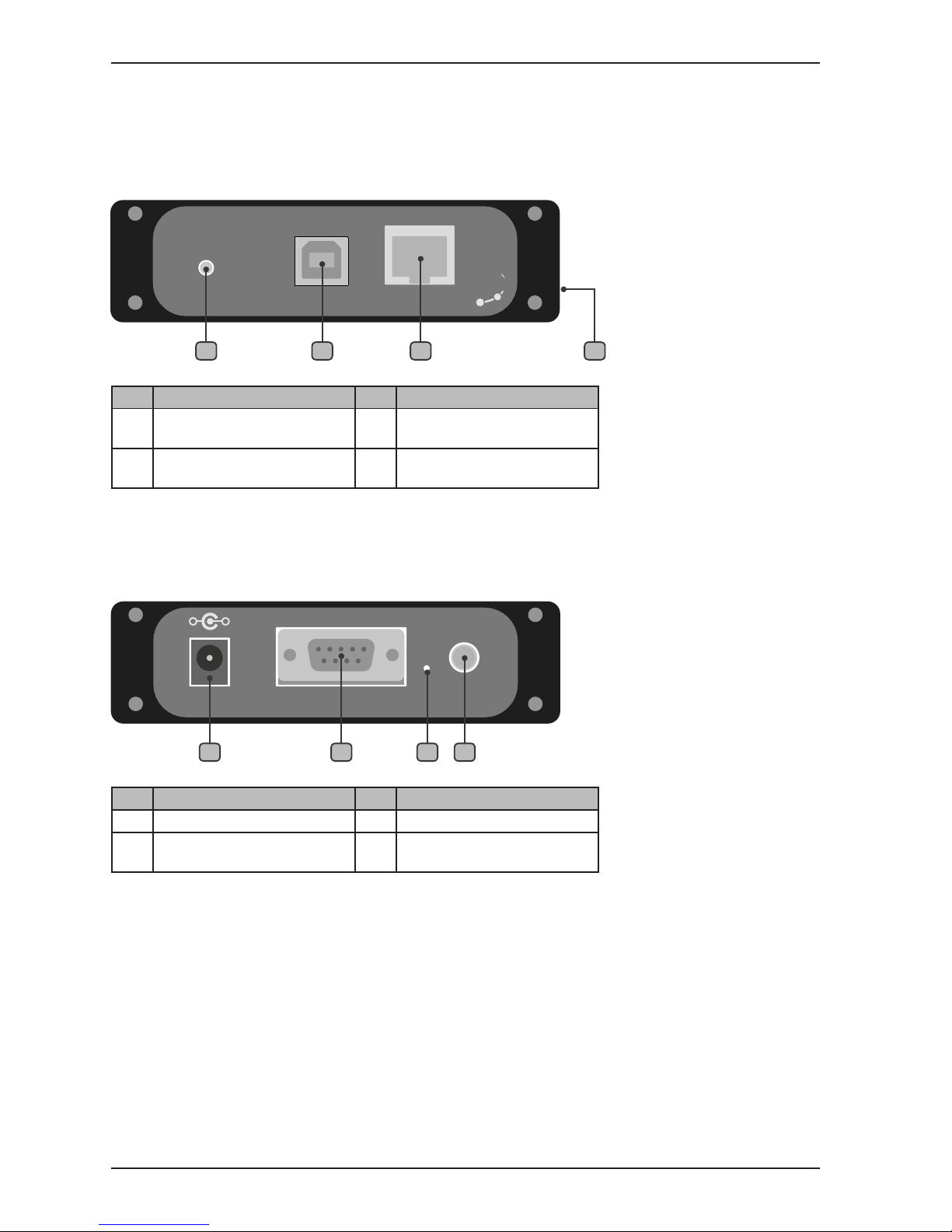
The drawings below show the front and rear of the Syncbox.
1.3.1 - Syncbox front view
No. Function No. Function
1
Status LED
3
Ethernet port (Ethernet
versions only)
2
USB setup port
4
Removable bracket xing
point
Table 1.1 - Front panel functions
No. Function No. Function
5
Power input
7
Software update switch
6
RS-232, RS-485 and PPS
outputs (Serial versions only)
8
GPS antenna connection
Table 1.2 - Rear panel functions
1.3.2 - Syncbox rear view
SYNCBOX
GPS TIME SERVER
STATUS
SETUP ETHERNET
Soluti ons
Worl d Time
1 2 3 4
RS-232 / RS-485 OUTPUT ANTENNA5V DC
GPS
www.worldtimesolutions.com
+
-
76 85
Page 7
3Syncbox - GPS Time Server - User Manual - Version 2.1
Section 1: Introduction
1.4 - The status LED
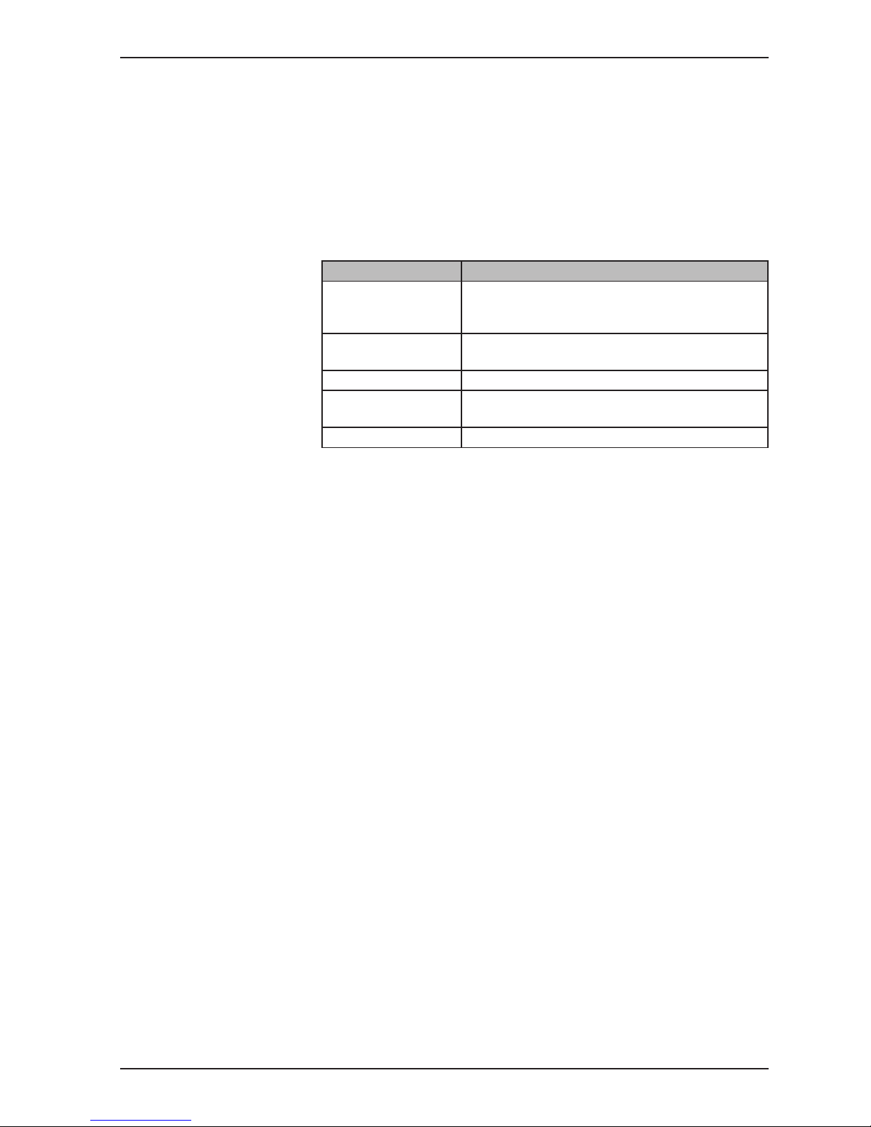
The status LED shows the general status of your Syncbox GPS Time
Server. When the Syncbox is operating normally, the LED will be
green and ashing once per second (the ash indicates the second
edge).
Table 1.3 below lists the different modes of operation of the status
LED and what each mode indicates.
LED operation Status
Green (ashing once
per second)
The Syncbox is synchronised to the GPS
satellites and is operating normally. (The ash
indicates the start of the second).
Red (ashing once
per second)
The Syncbox is not synchronised to the GPS
satellites.
Red (not ashing) The Syncbox is booting up.
Red (ashing fast) There is an error. Your Syncbox will automatically
reboot.
Yellow The Syncbox is in software update mode.
Table 1.3 - Status LED operation modes
Page 8

Syncbox - GPS Time Server - User Manual - Version 2.14
2 - Installing your Syncbox
The Syncbox is housed in a robust aluminium enclosure. The unit
is supplied complete with an active patch GPS antenna (or anti-jam
antenna kit), a power adapter and associated cables.
Please install your Syncbox following the notes below. To congure
your Syncbox, please refer to sections 3 (Syncbox Control software),
4 (The Ethernet port) and 5 (RS-232/RS-485 output).
2.1 - Physical installation
The Syncbox should be placed on a at surface. Alternatively, the
Syncbox can be secured to any surface using the supplied removable
brackets.
2.2 - Connecting and installing the GPS antenna
If your Syncbox has been supplied with the anti-jam antenna kit, please disregard
this section and consult the user manual supplied with the anti-jam kit.
For your Syncbox to operate reliably, the GPS antenna needs to have
at least a partial view of the sky (increasing the amount of sky visible
will provide correspondingly better performance).
The antenna should be mounted either externally (in a protected
position) or in an internal position with a view of the sky (for example,
on a window ledge). If you choose to mount your antenna internally,
best operation will be achieved by choosing a window facing towards
the equator (ensure the window is not coated with a metallised lm as
this may disrupt the GPS signals).
Once installation is complete, you may choose to secure the GPS patch antenna in
position using the adhesive tape supplied.
Connect the GPS patch antenna cable to the ‘GPS ANTENNA’
connection on the rear of the Syncbox.
2.3 - Power connection
The Syncbox is supplied with an external power adapter. The power
adapter should be connected to the Syncbox before being connected
to a local mains power supply.
2.4 - USB setup port
Please note: The USB drivers should be installed before connecting the Syncbox
to your PC.
The USB setup port should be connected to a Windows PC running
the Syncbox Control software. Note that you only need to connect the
USB cable if you wish to check or change any settings.
Page 9

5Syncbox - GPS Time Server - User Manual - Version 2.1
Section 2: Installing your Syncbox
2.5 - Ethernet port (version dependent)
Please note: In order to prevent possible network setup conicts, it is recommended
that the Syncbox is not connected to the network before the Ethernet port has been
congured - see section 4.
The Syncbox should be connected to an Ethernet switch on a TCP/IP
network. The Syncbox has a 10BASE-T/100BASE-TX auto-sensing
Ethernet port and should be connected to the network using the
supplied CAT5 patch cable (or similar).
2.6 - RS-232/RS-485 output (version dependent)
The RS-232/RS-485 output provides user programmable serial time
and date messages and PPS (pulse per second) data. Please refer
to section 5 (RS-232/RS-485 output) for connection and setup details.
Page 10
Syncbox - GPS Time Server - User Manual - Version 2.16
3 - Syncbox Control software
Please note: The USB drivers should be installed before connecting the Syncbox
to your PC.
Syncbox Control is a Windows software application that acts as
the control panel for your Syncbox. To change any setting on your
Syncbox, connect it to your PC using the USB connection and open
the Syncbox Control software.
The Syncbox Control software and USB drivers are on a CD-ROM
supplied with your Syncbox. Alternatively, you can download a copy
from the World Time Solutions web site:
http://www.worldtimesolutions.com
3.1 - Installing the USB drivers
• Insert the CD-ROM into a DVD/CD reader on your Windows PC.
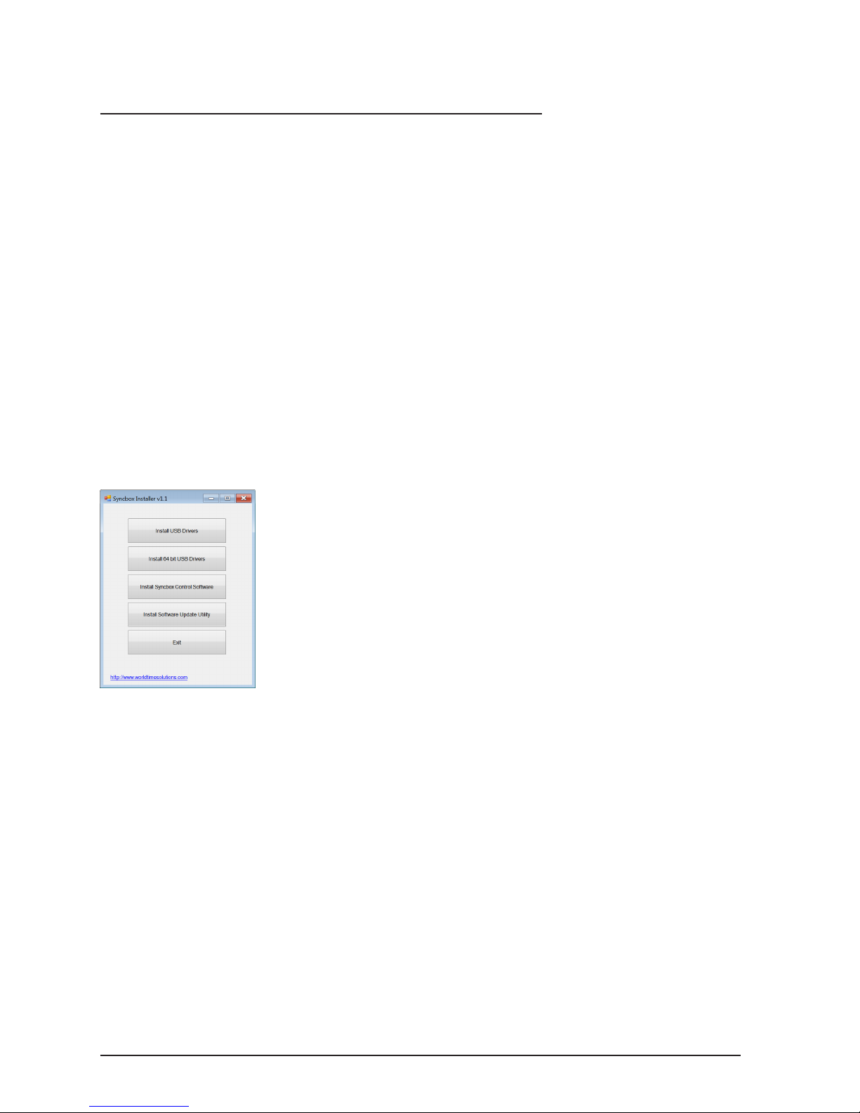
• The ‘Syncbox Installer’ program should automatically run. If the
program fails to start, run ‘SyncboxInstaller.exe’.
Fig 3.1 - The Syncbox Installer window
• Click ‘Install USB Drivers’ (or ‘Install 64 bit USB Drivers’ on 64 bit
versions of Windows).
• Follow the on-screen instructions to complete the USB driver
installation.
• Connect the Syncbox to your PC and follow the on-screen
instructions.
3.2 - Installing the Syncbox Control software
• Click the ‘Install Syncbox Control Software’ button.
• Follow the on-screen instructions to complete the installation.
• Once the software installation is complete, click the ‘Exit’ button.
Page 11
7Syncbox - GPS Time Server - User Manual - Version 2.1
Section 3: The Syncbox Control software
3.3 - Using the Syncbox Control software
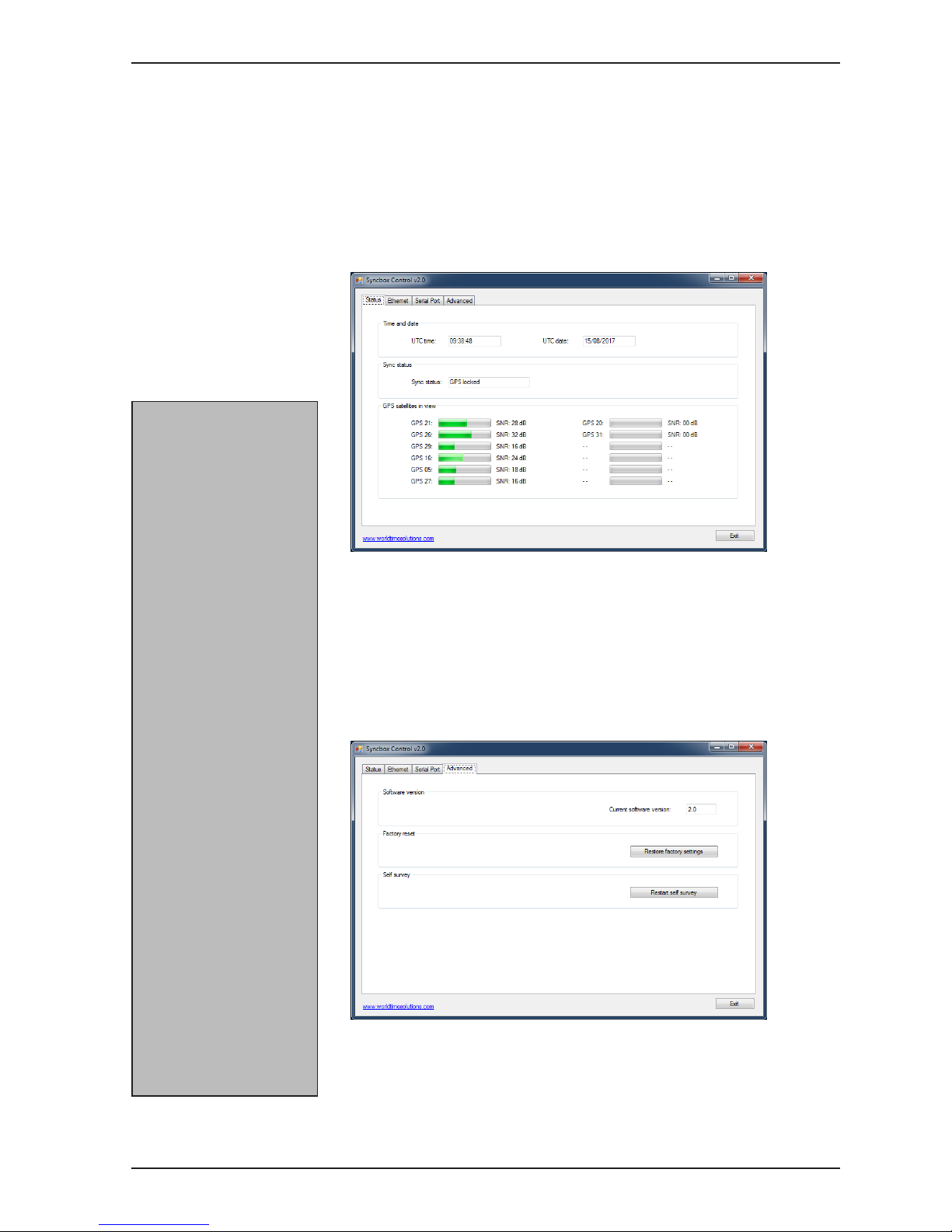
The main window of the Syncbox Control software uses a tab menu
system. Tabs are provided for the setup of each output (Ethernet
and Serial - please refer to sections 4 and 5 respectively), advanced
settings and a general status tab.
The General Status tab (shown in g 3.2 below) shows the UTC time
and date, and the GPS synchronisation status.
Fig 3.2 - The Syncbox Control software - General Status tab
The Advanced Settings tab (shown in g 3.3 below) indicates the
current software version in your Syncbox. There are also buttons to
restore your Syncbox to its factory settings and to erase the stored
location and restart the self survey.
Fig 3.3 - The Syncbox Control software - Advanced Settings tab
What is the self survey?
The Syncbox GPS Time Server
is designed to provide highly
accurate time data. In order
to achieve this, the Syncbox
needs to calculate its position
precisely.
The rst time you power up
your Syncbox it will perform
an automatic self survey
(the survey takes 35 minutes
to complete and requires the
Syncbox to be locked to the GPS
satellites). When the survey
is completed, the Syncbox
switches to a time only GPS
mode (where the location
is assumed not to change),
signicantly improving the
timing accuracy.
Once the survey is complete,
the location is stored in
the Syncbox. This ensures
accurate timing, even if the
Syncbox is rebooted.
If you relocate the GPS
antenna by a signicant
distance, the Syncbox will
detect this and automatically
perform another self survey.
Alternatively you can
manually trigger this by
clicking the ‘Restart self survey’
button (see g 3.3).
Page 12
Syncbox - GPS Time Server - User Manual - Version 2.18
4 - The Ethernet port
Note: The Ethernet port is only available on Ethernet versions.
The Ethernet port enables synchronisation of NTP/SNTP clients
over a network. With sub 30 μsec timestamp accuracies and high
bandwidth (5000 NTP requests per second) operation, the Syncbox
is the ideal network timing solution for a wide range of applications.
4.1 - Programming the Ethernet port
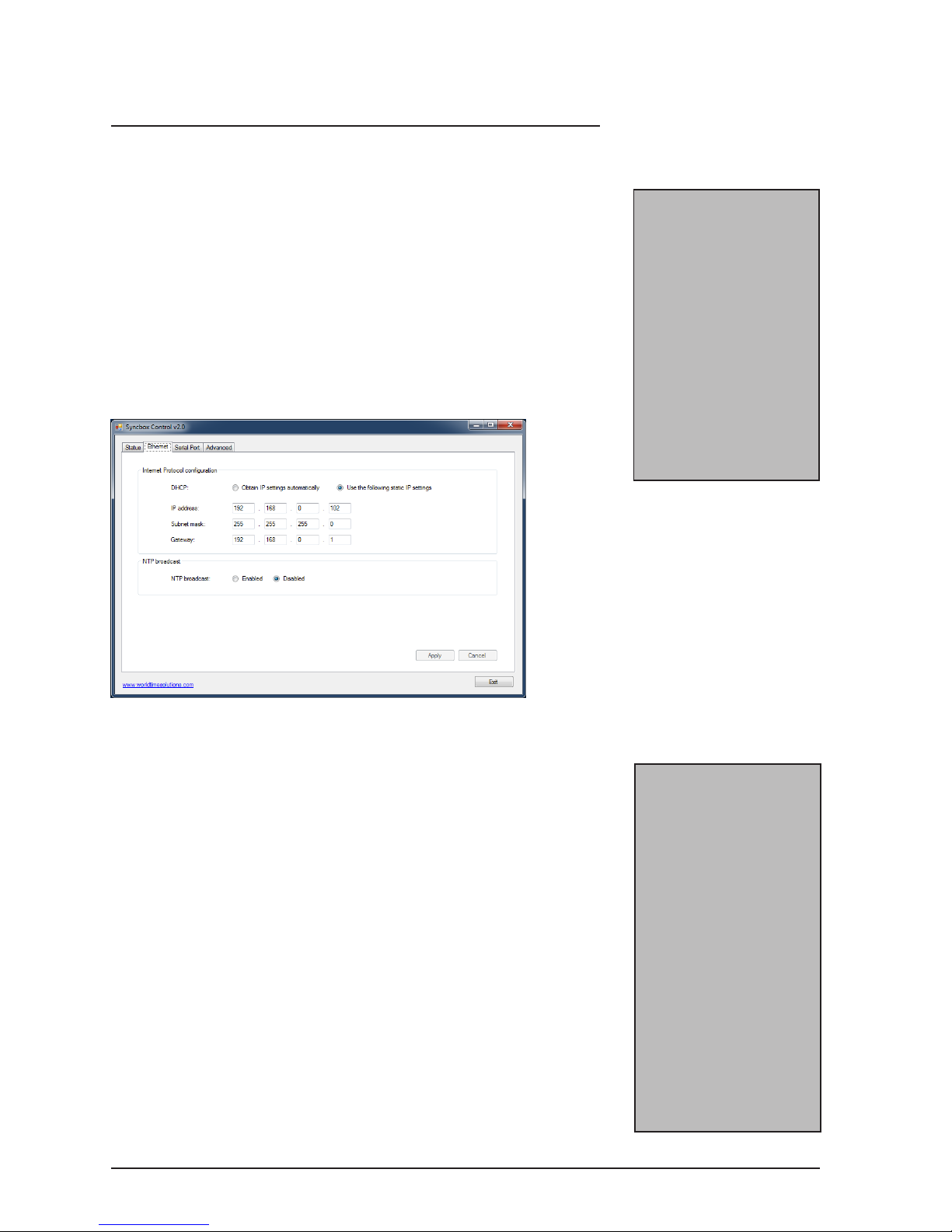
All settings related to the Ethernet port are congured using the
Syncbox Control software (refer to section 3 for further details). Figure
4.1 below shows the Ethernet conguration screen.
Fig 4.1 - The Syncbox Control software - Ethernet setup tab
The Syncbox Control software initially shows the currently programmed
Ethernet settings. If you make a change to any of the Ethernet
settings, the ‘Apply’ and ‘Cancel’ buttons will be enabled. Clicking the
‘Apply’ button will recongure your Syncbox with the new settings. If
you don’t wish to apply your new setting, click the ‘Cancel’ button.
4.2 - DHCP operation
The network interface can operate with DHCP (Dynamic Host
Conguration Protocol) enabled or disabled. When DHCP operation
is enabled, the Syncbox attempts to obtain network address settings
automatically from a DHCP server on the network. With DHCP
disabled, network address settings are manually entered into the unit.
If you congure the DHCP setting to ‘Obtain IP setting automatically’
(DHCP enabled) and the Syncbox has obtained its network settings,
the new settings will be displayed in the IP address, Subnet mask and
Gateway text boxes.
What is DHCP?
Dynamic Host Conguration
Protocol (DHCP) enables the
automatic assignment of IP
address settings on a TCP/IP
network.
Upon connection to a
TCP/IP network, a client
device congured for DHCP
operation communicates with
the DHCP server and obtains
an IP address lease.
The DHCP protocol is dened
in RFC 2131, available for
download from:
http://www.r fc-editor.org
What is NTP?
Network Time Protocol (NTP)
enables the synchronisation
of computer clocks across data
networks. It was originally
proposed in the early 1980s
and has been continually
updated and used ever since.
Further information may be
found at the home of the NTP
project:
http://www.ntp.org
Page 13

9Syncbox - GPS Time Server - User Manual - Version 2.1
Section 4: The Ethernet port
If you congure the DHCP setting to ‘Use the following static IP settings’
(DHCP disabled), the Syncbox uses the IP address, Subnet mask
and Gateway as programmed in the Internet Protocol conguration
window.
4.3 - NTP Broadcast
In a typical computer network, NTP operates in Unicast mode: an
NTP client requests the time and the Syncbox responds directly to
this request. However, in certain applications, it may be desirable to
congure the Syncbox to operate in broadcast mode.
When operating in NTP broadcast mode, as well as responding directly
to Unicast NTP requests, the Syncbox additionally broadcasts NTP
messages to all devices on the local Subnet. Broadcast messages
are transmitted every 64 seconds.
Page 14
Syncbox - GPS Time Server - User Manual - Version 2.110
5 - RS-232/RS-485 output
Note: The RS-232/RS-485 output is only available on serial versions.
The RS-232/RS-485 serial output provides time and date information
at both RS-232 and RS-485 signal levels. The data format can be
chosen by the user from a list of more than 25 different formats. The
serial port also outputs high accuracy PPS (pulse per second) data at
RS-232 signal levels.
5.1 - Connecting to the RS-232/RS-485 output
The Syncbox has a female DB-9 (DE-9) D-Sub (DTE) connector.
Table 5.1 shows the pin connections.
Pin Signal Source Description
1 PPS
Output
RS-232 Pulse Per Second
2 TXD
Output
RS-232 Transmitted data
3 RXD
Input
RS-232 Received data
5 GND
-
Signal ground
8 A Output RS-485 data A (non-inverting)
9 B Output RS-485 data B (inverting)
4, 6, 7 unused
-
-
Table 5.1 - RS-232/RS-485 serial port pin connections
5.2 - Programming the RS-232/RS-485 output
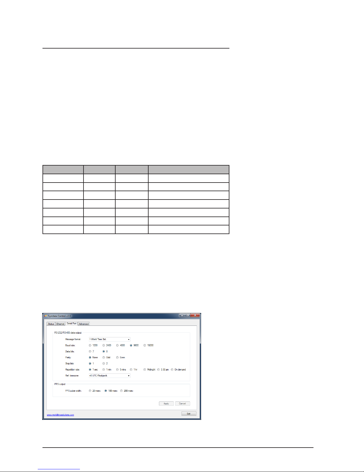
The RS-232/RS-485 serial data outputs and the PPS output are
congured using the Syncbox Control software (refer to section 3 for
further details). Figure 5.1 below shows the Serial Port conguration
screen.
Fig 5.1 - The Syncbox Control software - Serial Port tab
Page 15

11Syncbox - GPS Time Server - User Manual - Version 2.1
Section 5: RS-232/RS-485 output
The Syncbox Control software initially shows the currently programmed
settings. If you make a change to any of the Serial Port settings,
the ‘Apply’ and ‘Cancel’ buttons will be enabled. Clicking the ‘Apply’
button will recongure your Syncbox with the new settings. If you
don’t wish to apply your new setting, click the ‘Cancel’ button.
5.3 - Serial data message format and repetition rate
Serial data is transmitted in one of more than 25 message formats.
Available message formats are listed in appendix B.
The baud rate, data bits, parity and stop bits should be congured as
required for your application.
RS-232/RS-485 data messages are transmitted aligned with the
second edge. The Syncbox can be user-programmed to output a
data string every second, or periodically (see Repetition Rate option
in g 5.1).
When set to the ‘on demand’ repetition rate, the Syncbox will only
output serial data on receipt of a valid transmission request character
on the RS-232 RXD pin. Valid characters are ‘s’ (0x73), ‘S’ (0x53), ‘t’
(0x74), ‘T’ (0x54) and ‘?’ (0x3f). The data transmission starts on the
second edge after a valid request character has been received.
5.4 - Reference time zone
The RS-232 and RS-485 data messages can be output referenced
to any of the preprogrammed time zones. Appendix C lists the
preprogrammed time zones along with offsets from UTC.
Where applicable, the preprogrammed time zones incorporate
seasonal time change information, allowing changes to occur
automatically.
5.5 - PPS (pulse per second) output
The PPS (pulse per second) pin provides a high accuracy pulse every
second, aligned with the second edge. The pulse is transmitted at
RS-232 signal levels from pin 1 of the serial port.
The PPS pin is normally at a negative voltage level (RS-232 logic
state 1). At the start of the second edge, the pin switches to a positive
voltage level (RS-232 logic state 0). After the PPS pulse has ended,
the pin switches back to a negative voltage level.
The width of the PPS pulse may be adjusted from 20 msec to 200
msec.
What is UTC?
In the early 1970s, with the
increase in timing accuracy
made available by modern
atomic clocks, Coordinated
Universal Time (UTC) replaced
Greenwich Mean Time (GMT)
as the world’s time scale.
Historically, GMT calculated
the length of a day based on
solar time patterns. UTC uses
highly accurate atomic clocks
as a calculation base.
Page 16

Syncbox - GPS Time Server - User Manual - Version 2.112
6 - Software updates
Occasionally, an updated software version may become available for
the Syncbox. The updated software should be installed using the
Syncbox Software Update Utility. The Syncbox Software Update
Utility is packaged as part of the Syncbox Control software.
The Syncbox Control software (including the Syncbox Software
Update Utility) is supplied on a CD-ROM along with your Syncbox.
Alternatively, the latest version may be downloaded from the World
Time Solutions web site:
http://www.worldtimesolutions.com
6.1 - Installing the Syncbox Software Update Utility
• If the USB drivers have not previously been installed on your
PC, install them now using the Syncbox Installer software (see
section 3.1).
• In the Syncbox Installer window, click ‘Install Software Update
Utility’ (see section 3).
• Follow the on-screen instructions to complete the installation.
• Once the software installation is complete, click the ‘Exit’ button.
6.2 - Downloading the updated software version
• Visit the World Time Solutions web site and navigate to the
Syncbox downloads page.
• Right click the new Syncbox software version and ‘Save link as...’
• Select a directory on your computer.
• Navigate to the new directory.
• Right click the new software zip le and select ‘Extract All...’
• Follow the instructions on screen to extract the zip le to a new
directory.
6.3 - Applying a software update
BEFORE STARTING THIS PROCEDURE, PLEASE ENSURE
THE SYNCBOX CONTROL SOFTWARE / SOFTWARE UPDATE
UTILITY APPLICATIONS ARE NOT RUNNING. PLEASE ALSO
DISCONNECT THE SYNCBOX FROM THE POWER SUPPLY.
• Connect the Syncbox to the PC using a standard USB printer
cable.
Page 17

13Syncbox - GPS Time Server - User Manual - Version 2.1
Section 6: Software updates
• Insert a paper clip (or similar small implement) into the software
update switch hole on the rear of the Syncbox (point 7 on the
drawing in section 1.3.2).
• Whilst ensuring the software update switch is active (pressed in),
apply power to the Syncbox.
• The Syncbox will power up in software update mode (the front
panel status LED should be yellow - if not, please remove and
reapply power ensuring the switch is pressed in).
The remaining steps are performed using the Syncbox Software
Update Utility.
• Open the Syncbox Software Update Utility software.
• Click the ‘Browse’ button. A ‘File Open’ window will appear.
• Select the recently downloaded and extracted le (SyncboxT_x.x)
and click ‘Open’. The new le version will now be displayed in
the ‘New Software Version’ text box.
• Click the ‘Start Update Procedure’ button. The replacement
software will now be uploaded into the Syncbox via the USB
connection. The ‘Software Update Progress’ section details the
procedures being performed and overall progress.
• Once the update is complete, click on the ‘Exit’ button.
Page 18
Syncbox - GPS Time Server - User Manual - Version 2.114
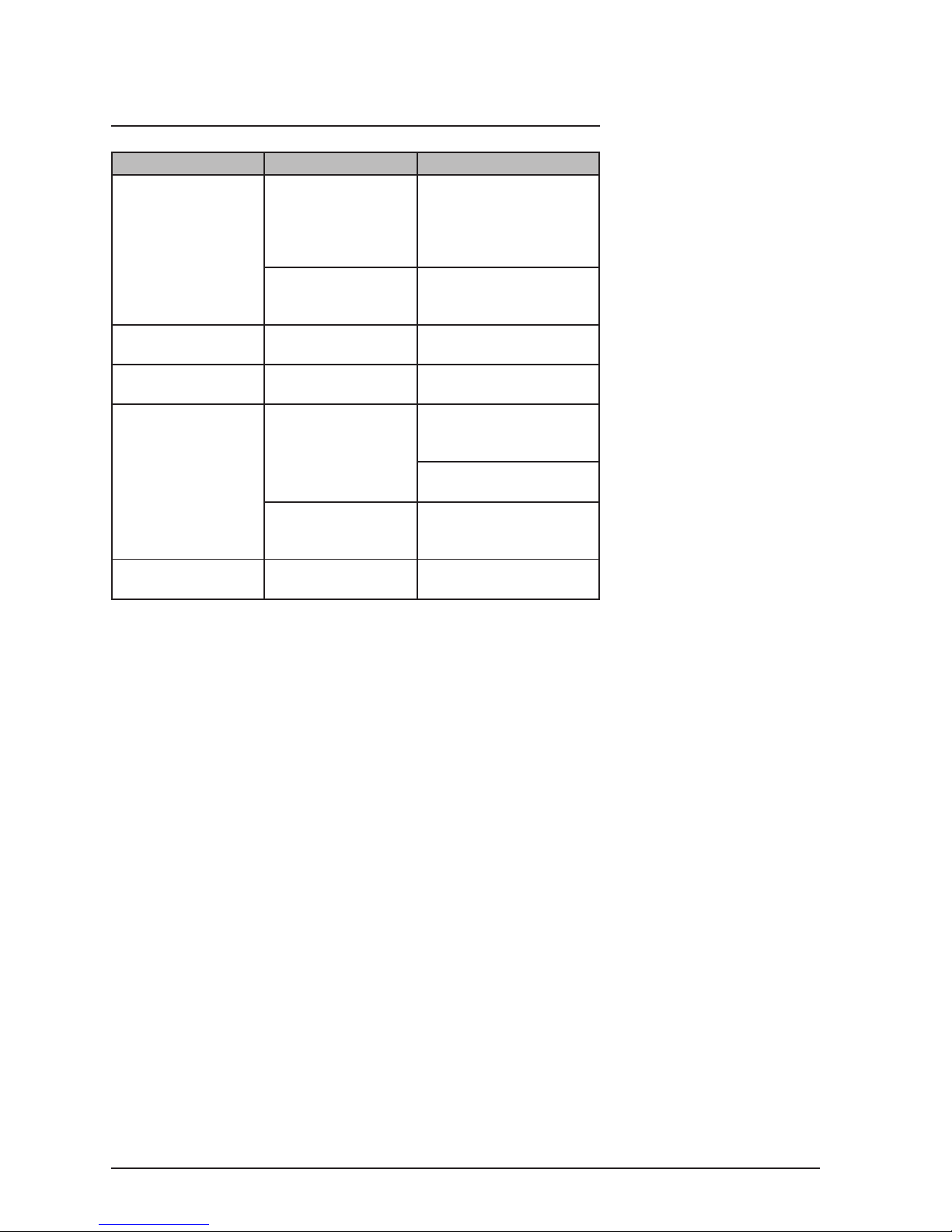
A - Troubleshooting
Problem Possible Cause Solution
Status LED is Red
and ashing once per
second (indicates a
time synchronisation
error)
The Syncbox is not
yet synchronised
after power up
Even with a good view of
the sky, the Syncbox may
take up to 15 minutes to
synchronise after power
up
Poor antenna sky
visibility
Ensure the antenna has a
clear view of the sky (see
section 2.2)
Status LED is Red
and not ashing
The Syncbox is
booting up
Wait for boot up to
complete
Status LED is Red
and ashing fast
There is an error The Syncbox will
automatically reboot
Not responding to
NTP requests
No connection to the
network
Check Ethernet port
conguration (see section
4)
Check network switch and
CAT5 patch cable integrity
The Syncbox is not
synchronised to GPS
satellites
Refer to Time
synchronisation error
section above
RS-232/RS-485
output error
Serial port
programming error
Check Serial Port setup
(see section 5)
Table A.1 - Troubleshooting guide
Page 19

15Syncbox - GPS Time Server - User Manual - Version 2.1
B - Serial message formats
The table below lists the message formats available from the RS-232
and RS-485 serial data outputs. Please refer to section 5 for further
details.
No. Message format Notes
1 World Time Solutions standard format
2 World Time Solutions long format
3 World Time Solutions short format
4 NMEA GGA
5 NMEA RMC
6 NMEA ZDA
7 Spectracom NetClock/2 format 0
8 Spectracom NetClock/2 format 1
9 Spectracom NetClock/2 format 2
10 Spectracom NetClock/2 format 3
11 Spectracom NetClock/2 format 4
12 EES M100
13 EES M201
14 Meinberg Standard time string
15 Computime Time String
16 Sysplex 1
17 Wtn. format 1
18 Wtn. format 1 (without status)
19 Wtn. format 2
20 Wtn. format 2 (with day of week)
21 Racal XGU
22 Tecton Darlex (03:30 & 03:31 only)
23 TAIP AL (Altitude / Vertical Velocity)
24 TAIP CP (Compact Position)
25 TAIP LN (Long Navigation)
26 TAIP PV (Position / Velocity)
27 TAIP TM (Time / Date)
Table B.1 - Serial message formats
Page 20

Syncbox - GPS Time Server - User Manual - Version 2.116
C - Serial output time zones
The Syncbox can output serial time and date data referenced to
any of the following preprogrammed time zones. Time zone offsets
followed by a * character indicates that the time zone has daylight
saving changes (performed automatically).
UTC Offset City / Time Zone
0 UTC/Reykjavik
0* London/Dublin/Lisbon
0* Casablanca
+1 Lagos/Algiers
+1* CET/Paris
+2 Cape Town/Johannesburg/Harare
+2* Athens/Soa
+2 Cairo
+2* Jerusalem
+2* Beirut
+2* Amman
+3 Khartoum/Nairobi/Baghdad
+3* Moscow (old - pre 2012)
+3.5* Tehran
+4 Dubai/Moscow
+4.5 Kabul
+5 Karachi
+5.5 Mumbai/New Delhi
+5.75 Kathmandu
+6 Almaty/Dhaka
+6.5 Yangon
+7 Bangkok/Jakarta
+8 Singapore/Hong Kong/Beijing
+8* Perth
+9 Seoul/Tokyo
+9.5 Darwin
+9.5* Adelaide
+10 Brisbane
+10* Vladivostok
+10* Melbourne/Canberra/Sydney
+11 -
+12 Suva
+12* Kamchatka/Anadyr
+12* Auckland
+12.75* Chatham Island
+13 -
+14 Kiritimati
Table C.1 - Preprogrammed Serial Output Time Zones
Page 21

17Syncbox - GPS Time Server - User Manual - Version 2.1
Appendix C: Serial output time zones
UTC Offset City / Time Zone
-10 Honolulu
-9 -
-9* Anchorage
-8 -
-8* Vancouver/San Francisco
-7 Phoenix
-7* Edmonton/Denver
-6 Guatemala/San Salvador/Managua
-6* Winnipeg/Houston/Chicago
-6* Mexico City
-5 Lima/Kingston/Bogota
-5* New York/Toronto/Nassau
-5* Havana
-4.5 Caracas
-4 Santo Domingo/La Paz/San Juan
-4* Halifax
-4* Santiago
-3.5* Newfoundland
-3 -
-3* Brasilia/Sao Paulo
-3* Montevideo
-3 Buenos Aires
-2 -
-1 -
Table C.1 - Preprogrammed Serial Output Time Zones (cont..)
Page 22
Syncbox - GPS Time Server - User Manual - Version 2.118
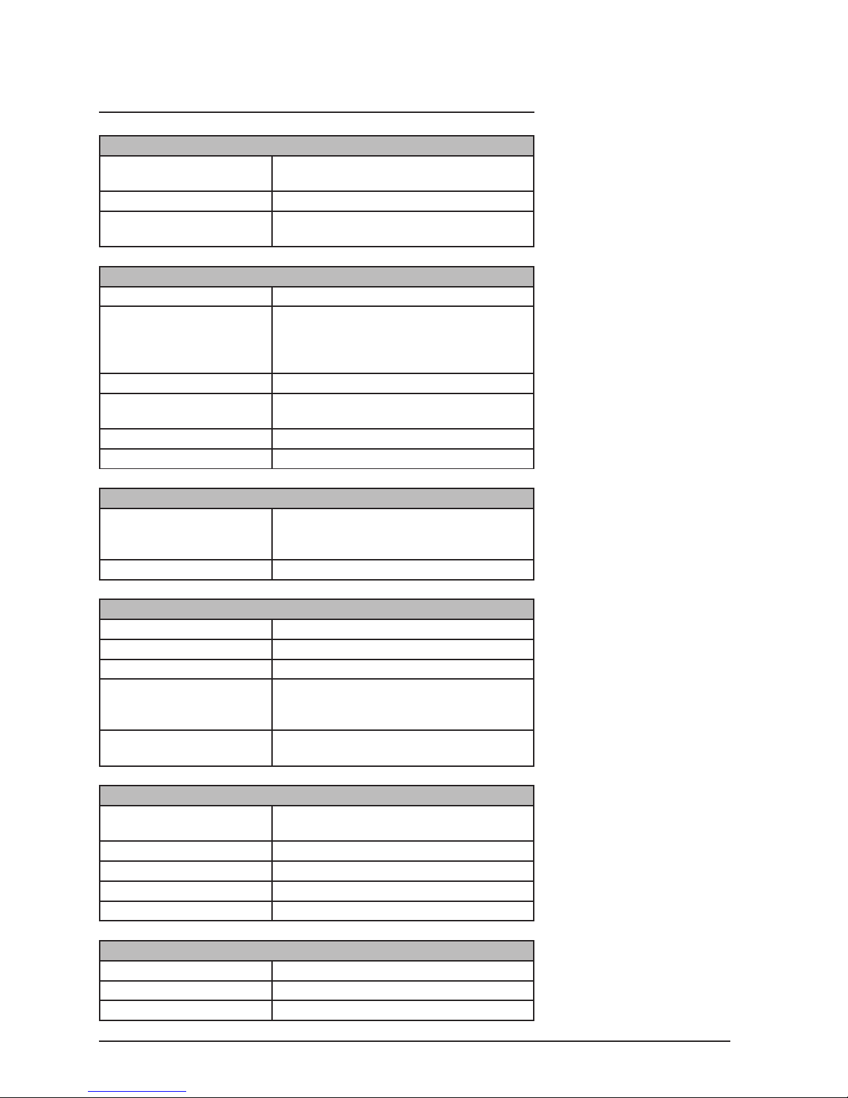
D - Specications
Model Variations & Availability
Syncbox-S: RS-232 and RS-485 level serial outputs
and PPS output
Syncbox-N: NTP/SNTP Ethernet output
Syncbox-SN: NTP/SNTP Ethernet output, RS-232 and
RS-485 level serial outputs and PPS output
Typical Performance Specications
NTP timestamp accuracy: Typically within 30 μsec of UTC
NTP client accuracy: Dependent on network architecture,
utilisation, delays and jitter. Clients typically
synchronised to within 200 μsec to 2 msec
of UTC on a LAN.
NTP performance: 5000 NTP requests per second
RS-232/RS-485 output
accuracy:
50 µsec
PPS output accuracy: 1 µsec
PPS output jitter: 30 nsec
Supported Protocols
Ethernet protocols: NTP v2 (RFC 1119), NTP v3 (RFC 1305),
NTP v4 (no RFC), SNTP v3 (RFC 1769),
SNTP v4 (RFC 2030), DHCP
Serial protocols: More than 25 serial data formats
I/O Connections
Ethernet connection: 10BASE-T / 100BASE-TX auto-sensing
RS-232/RS-485/PPS: DB-9 (DE-9) female D-Sub
Setup: USB 2.0 (full-speed)
GPS antenna: SMA (supplied with active patch antenna
and 2m captive cable - Anti-jam antenna kit
option available)
Power input: 5V DC power input, supplied with external
power adapter
Mechanical, Electrical & Environmental Specications
Dimensions: 112 x 33 x 92mm (4.4” x 1.3” x 3.6”)
(excluding removable wall xings)
Weight: 0.5 kg
Power consumption: 0.5 AMPS (@ 5 VDC)
Operating temperature: 0 to 50 ºC
Relative humidity: 0% - 95%, noncondensing
Standards
Electrical Safety: BS EN 60950-1:2006
Radio Disturbance: BS EN 55022:2006 (class B)
Immunity Characteristics: BS EN 55024:2003
Page 23
19Syncbox - GPS Time Server - User Manual - Version 2.1
E - Certicate of Conformity
Page 24

World Time Solutions Limited
The Gatehouse, Gatehouse Way, Aylesbury, Buckinghamshire, HP19 8DB, United Kingdom
+44 (0) 1296 331428 - [email protected]
www.worldtimesolutions .com
 Loading...