

Page 1

Page 2

THE CONNECTED INFRASTRUCTURE SOLUTION
MONITORING HOW STRUCTURES EVOLVE
Loadsensing is a data acquisition and monitoring system
which combines state-of-the-art wireless monitoring and
advanced software tools. It is widely recognized as the leading
solution for connecting and monitoring infrastructures in
remote locations.
Loadsensing devices are battery-powered and equipped
with long-range, low-power wide area network (LPWA) radio
communications and are compatible with a wide range of
geotechnical sensors. The software suite is web-based and
facilitates real-time data capture and analytics. It is also
possible to set automatic alarms to make operations safer.
Mining and construction companies and operators of
bridges, tunnels, dams, railways and many other inaccessible
assets can now work with reliable data. Having access to
this information and real-time insights enables operators to
anticipate needs, manage their workforce, diminish risks,
and even prevent disasters.
FEATURES BENEFITS
Long-range communication of over 9 miles / 15km
Truly low-power, 10 years of unattended runtime
Wireless LPWA communication
Supports most structural and geotechnical sensors
(vibrating wire, digital, analog)
Wireless tiltmeter
Integrated alarm system
User-friendly web software
Leverage already formatted data to optimize operations
Remotely monitor hard-to-access infrastructures
Cover a wide area with geotechnical sensors
Easily add sensors to extend measurement range
Save resources through fast implementation
Decrease costs through easy maintenance
Diminish risks and make operations safer
Page 3

SOFTWARE SUITE
NETWORK AND ASSET MANAGEMENT SOFTWARE
Network communications conguration and control
Wireless data unit and sensor attributes display
Wireless data unit conguration
Sensor data in near real time
Conversion of raw sensor data in engineering units
Manual and automatic data download in .csv
Data transmitted in a secure manner
Remote change of sensor’s sampling rate
Data accessible through Modbus TCP
Able to push data on user FTP
DATA MANAGEMENT SOFTWARE
Sensor data visualization and download (tables and graphs)
Topological view
Creation of virtual variables
Conguration of alarm thresholds
Alarms sent to stakeholders by email
Automatically generated reports (tables, graphs and notes)
HOW IT WORKS
Operational Intelligence
for Mines and Industrial Companies
Worldsensing is not only among the best in the world at
connecting distributed infrastructures with smart devices,
we also know how to extract intelligence from collected data
to transform operations. Our software solutions combine
location intelligence with infrastructure monitoring.
Page 4
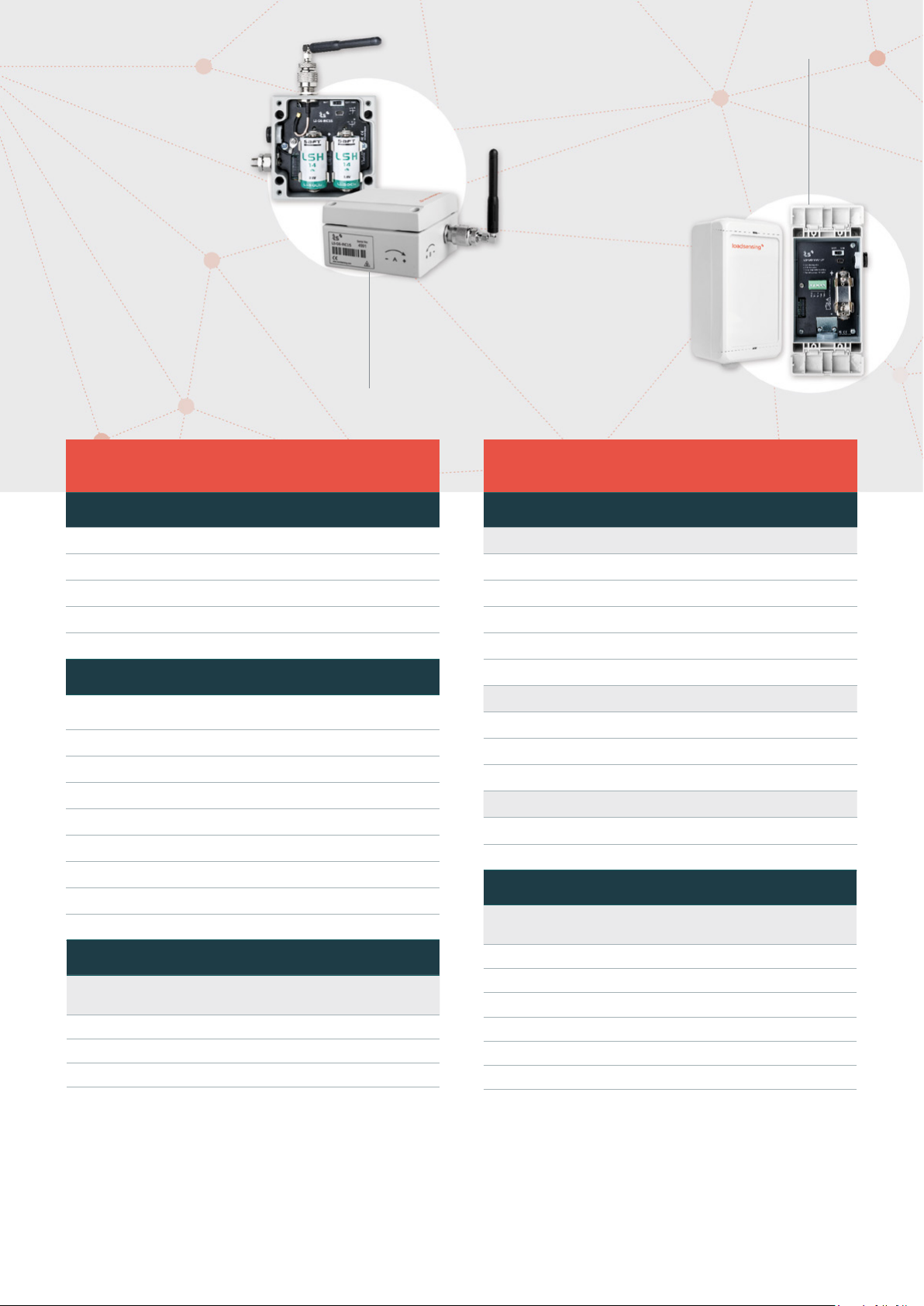
NODE: LS-G6-INC15
BOX DIMENSIONS (WxLxH): 100x100x61 mm
OVERALL DIMENSIONS: 150x120x61 mm (excluding antenna)
EXTERNAL ANTENNA: 100 mm length (including connector)
HOUSING MATERIAL: Aluminium alloy
Internal C-size 3.6 V High power batteries, from 1 up to 2 batteries
NODE: LS-G6-VW-1P (POLYCARBONATE)
BOX DIMENSIONS (WxLxH): 151x80x60 mm
OVERALL DIMENSIONS: 160x85x60 mm
INTERNAL ANTENNA
RADIO COVERAGE: 60 % of the achieved with the external antenna
WITHOUT GROUNDING
HOUSING MATERIAL: Polycarbonate
Internal C-size 3.6 V High power batteries, 1 battery
WIRELESS TILTMETER
LS-G6-INC15
APPLICATIONS
Remote tilt monitoring from retaining and building walls
Landslide monitoring
Bridge pier monitoring
Structural load monitoring
Ground subsidence
SPECIFICATIONS
Type:
Range:
Accuracy (± 5⁰): 0.03% FS / 0.004⁰
Accuracy full range: 0.17% FS / 0.025⁰
Resolution: 0.001°
Repeatability: 0.005°
Axes: Two (biaxial)
Temperature sensor resolution: 0.1 ⁰C
Temperature sensor accuracy: ±0.5 ⁰C
BATTERY LIFE ESTIMATION Wireless tiltmeter
SAMPLING RATE
Barcelona
temperature prole
5 min 1.2 years 1.1 years
1 h 5.8 years 4.7 years
6 h 8.3 years 6.4 years
MEMS (Micro-Electro-Mechanical)
Inclinometer
± 15⁰
Singapore
*
temperature prole*
VIBRATING WIRE 1ch and 5ch NODES
LS-G6-VW-1P, LS-G6-VW-1M, LS-G6-VW-5
VIBRATING WIRE NODE 1ch and 5ch
VIBRATING WIRE
Measurement method: Embedded algorithms increasing immunity to noise
Excitation wave: +/- 5 V
Measurement range: 300 to 7,000 Hz
Resolution (-40 to +85ºC): 0.12 Hz
Accuracy (-40 to +85ºC): 0.018 % FS
THERMISTOR
Measurement range: 0 ohm to 4 Mohm
Resolution: 1 ohm
Accuracy (20ºC): 0.05ºC (0.04 % FS)
BAROMETER
Pressure Range: 300 to 1,100 hPa
Relative Accuracy (950 to 1,050 hPa at 25ºC): ±0.12 hPa
BATTERY LIFE ESTIMATION Vibrating wire nodes
CHANNELS
& SAMPLING
1 CH 5 min 1 cell 3 years
1 CH 30 min 1 cell 7 years
5 CH 5 min 1 cell 1,5 years
5 CH 5 min 4 cell 5 years
5 CH 30 min 1 cell 4 years
5 CH 30 min 4 cell >10 years
BATTERIES*
BATTERY LIFE
ESTIMATION
*
* Estimations for 2 x saft LSH 14 batteries
Specications are subject to review and change without notice
* Nominal capacity of each battery: 5,8 Ah.
Considering laboratory conditions
Page 5

Nodes: LS-G6-ANALOG-4, LS-G6-DIG-2 and LS-G6-VW 5 ch
EXTERNAL ANTENNA: 114 mm length (including connector)
Internal C-size 3.6 V High power batteries, from 1 up to 4 batteries
NODE: LS-G6-VW-1M (ALUMINIUM)
BOX DIMENSIONS (WxLxH): 100x100x61 mm
OVERALL DIMENSIONS: 140x120x61 mm (excluding antenna)
EXTERNAL ANTENNA: 114 mm length (including connector)
HOUSING MATERIAL: Aluminium alloy
Internal C-size 3.6 V High power batteries, 1 battery
BOX DIMENSIONS (WxLxH): 100x200x61 mm
OVERALL DIMENSIONS: 140x220x61 mm
(excluding antenna)
HOUSING MATERIAL: Aluminium alloy
ANALOG NODE
LS-G6-ANALOG-4
ANALOG NODE 4ch
Each channel is individually congured by the user
Power supply: 5 V DC / 12 V DC / 24 V DC up to
60 mA selectable for each channel
VOLTAGE
Measuring ranges [V DC]: +/-10 ; +/-1.25 (8x)
Accuracy (-40 to +85ºC): +/- 0.05 % FS
CURRENT LOOP (2-3 wires)
Measuring range: 4-20 mA
Accuracy (0 to +50ºC): 0.05 % FS
POTENTIOMETER (POT)
Accuracy (0 to +50ºC): +/- 0.02 % FS
FULL WHEATSTONE BRIDGE (FWB)
Accuracy (0 to -50ºC): +/- 0.1 % FS
THERMISTOR
Accuracy (0 to +50ºC): +/- 0.2ºC
PT 100
Accuracy (20ºC): +/- 0.8ºC
Channels
&
Sampling
Current
@12V@24mA
BATTERY LIFE ESTIMATION **
Current
@24V@24mA
Voltage
@12V@24mA
FWB@5V@0.7 kΩPot@5V@1.5
kΩ
DIGITAL NODE
LS-G6-DIG-2
DIGITAL NODE
One RS485 channel and two SDI-12 channels
Power supply: 12 V DC up to 120 mA
RS485 full or half duplex supported
Suitable for a chain of in-place inclinometers
Modbus RTU RS485
Supported sensors: RTS, Sisgeo and Geosense digital inclinometers
BATTERY LIFE ESTIMATION **
RST and Sisgeo chains of Inclinometers
Number of
sensor
10 (RST) >10 years 2.5 years 4 months
30 (RST) 5.2 years 4 months 26 days
10 (SISGEO) 4 years 5 months 30 days
6 hours 30 minutes 3 minutes
Sampling rate
SHARED SPECIFICATIONS
INTERNAL DATA STORAGE
Up to 72,500 readings including time and 5 sensors
Up to 200,000 readings including time and 1 sensor
Sampling rate: 30 seconds to 1 day
Time synchronization by radio: Time discipline better than ± 10 seconds
Operating temperature: -40⁰C to 80⁰C (-40⁰F to 175⁰F)
Weather protection: IP67
Warm up
time
1 CH 5 min 6 months 4 months 5 months 1.5 years 1.5 years
1 CH 6
hours
4 CH 5
min
4 CH 6
hours
** Estimations for 4 x saft LSH 14 batteries.
Considering laboratory conditions
1 second 1 second 1 second
>10 years >10 years >10 years 8.5 years >10 years
1.5
months
8 years 6.5 years >10 years 8.5 years >10 years
39 days 2 months
1.5
months
7 months
ACCESSORIES
ACCESSORIES
Saft LSH 14 C-size spiral cell
Node-mobile cable
External mounting brackets for wall mounting
Plate for pole mounting
Tiltmeter horizontal mounting plate
Tiltmeter vertical mounting bracket
Specications are subject to review and change without notice
Page 6

HOW IT WORKS IN MINES
Page 7

DLOG APP
Simple and fast connection to wireless node
BASE STATION
ISM Sub 1 GHz band, sensitivity: down to -137 dBm
Runs on Android devices
Easy sensor conguration: ID, sampling rate, frequency sweep, interface type, etc.
Checks radio signal coverage
Records coordinates (GPS)
Downloads data from wireless node and sends by e-mail or saves it on
the Android device
Takes current reading
Updates wireless node rmware
Detachable omnidirectional ½ dipole
Integrated GPS antenna
GNSS High Sensitivity GPS module
POWER
Power supply: 48 V DC PoE
Nominal: 3 Watts
DC power supply (ex.: solar panel use): 11 to 30 Volts
MECHANICAL
Size: 210 x 310 x 170 mm, including mounting kit
Weight: 2 kg including mounting kit
IP67 rating
Operating range: -20 to + 60 ºC
NETWORK INTERFACES
10/100 Ethernet WAN (RJ45 PoE)
Integrated 3G Modem & Antenna (HSDPA, EDGE, GPRS) quad band
LS gateways:
868 MHz ISM band
915 MHz FCC ISM band
915-928 MHz ISM band
Page 8

HOW IT WORKS IN CITIES
NOTE:
These distances are calculated for a standard antenna. A directional antenna will increase the range
RADIO & APPLICATIONS
LONG RANGE RADIO
OPEN FIELD: 15 km
CITY STREET: 4 km
MANHOLE IN A CITY STREET: 2 km
TUNNEL: 4 km
RADIO SPECS
ISM sub 1 GHz operating frequency bands adjustable to each territory
requirements
No repeaters needed
High sensitivity: down to -137 dBm
Transmission: +14 dBm high eciency / +20 dBm
Maximum link budget: 151 dB / 157 dB
Remote sampling rate change
Bidirectional communications capabilities
Aragó 383, 4th oor
08013 Barcelona, Spain
[+34] 93 418 05 85
sales@worldsensing.com
www.worldsensing.com
Visit our website:
Page 9

Regulatory Information USA
Changes or modifications not expressly approved by the party responsible for compliance could
void the user’s authority to operate the equipment.
This device complies with part 15 of the FCC Rules. Operation is subject to the following two
conditions: (1) This device may not cause harmful interference, and (2) this device must accept
any interference received, including interference that may cause undesired operation.
Class B device notice
NOTE: This equipment has been tested and found to comply with the limits for a Class B digital
device, pursuant to part 15 of the FCC Rules. These limits are designed to provide reasonable
protection against harmful interference in a residential installation. This equipment generates,
uses and can radiate radio frequency energy and, if not installed and used in accordance with
the instructions, may cause harmful interference to radio communications. However, there is
no guarantee that interference will not occur in a particular installation. If this equipment does
cause harmful interference to radio or television reception, which can be determined by turning
the equipment off and on, the user is encouraged to try to correct the interference by one or
more of the following measures:
—Reorient or relocate the receiving antenna.
—Increase the separation between the equipment and receiver.
—Connect the equipment into an outlet on a circuit different from that to which the
receiver is connected.
—Consult the dealer or an experienced radio/TV technician for help.
RF exposure safety
This device is a radio transmitter and receiver.
It is designed not to exceed the emission limits for exposure to radio frequency (RF) energy set
by the Federal Communications Commission.
The antenna must be installed and operated with minimum distance of 20 cm between the
radiator and your body.
This transmitter must not be co-located or operating in conjunction with any other antenna or
transmitter.
Permitted Antenna
This radio transmitter model, FCC ID: 24HN4-LS-G6-VW-1M has been approved by FCC to
operate with the antenna types listed below with the maximum permissible gain indicated.
Antenna types not included in this list, having a gain greater than the maximum gain indicated
for that type, are strictly prohibited for use with this device.
Type
Max Gain
External antenna: Wellshow AR017 GSM Quad Band
Antenna
+2 dBi
Page 10

Regulatory Information Canada
Changes or modifications not expressly approved by the party responsible for compliance could
void the user’s authority to operate the equipment.
Les changements ou modifications non expressément approuvés par la partie responsable de la
conformité pourraient annuler l'autorisation de l'utilisateur d'utiliser l'équipement.
This device complies with Innovation, Science and Economic Development Canada’s licenceexempt RSS(s). Operation is subject to the following two conditions: (1) This device may not
cause interference; and (2) This device must accept any interference, including interference that
may cause undesired operation of the device.
Le présent appareil est conforme aux CNR de l’ISDE applicables aux appareils radio exempts de
licence. L'exploitation est autorisée aux deux conditions suivantes : (1) l'appareil ne doit pas
produire de brouillage, et (2) l'utilisateur de l'appareil doit accepter tout brouillage
radioélectrique subi, même si le brouillage est susceptible d'en compromettre le fonctionnement.
RF exposure safety
This device is a radio transmitter and receiver.
It is designed not to exceed the emission limits for exposure to radio frequency (RF) energy set
by the ISED.
The antenna must be installed and operated with minimum distance of 20 cm between the
radiator and your body.
This transmitter must not be co-located or operating in conjunction with any other antenna or
transmitter.
Le modèle est un émetteur et un récepteur radio.
Il est conçu pour ne pas dépasser les limites d'émission pour l'exposition à l'énergie
radiofréquence (RF) établie par l'ISDE.
L’antenne doit être installé de façon à garder une distance minimale de 20 cm entre la source de
rayonnements et votre corps.
L’émetteur ne doit pas être colocalisé ni fonctionner conjointement avec à autre antenneou autre
émetteur.
Permitted Antenna
This radio transmitter model, IC: 21260-LSG6VW1M has been approved by the ISED to operate
with the antenna types listed below with the maximum permissible gain indicated. Antenna
types not included in this list, having a gain greater than the maximum gain indicated for that
type, are strictly prohibited for use with this device.
Type
Max Gain
External antenna: Wellshow AR017 GSM Quad Band
Antenna
+2 dBi
Le présent émetteur radio modèle, IC: 21260-LSG6VW1M a été approuvé par ISDE pour
fonctionner avec les types d'antenne énumérés ci-dessous et ayant un gain admissible maximal.
Page 11

Les types d'antenne non inclus dans cette liste, et dont le gain est supérieur au gain maximal
indiqué, sont strictement interdits pour l'exploitation de l'émetteur.
Type
Max Gain
External antenna: Wellshow AR017 GSM Quad Band
Antenna
+2 dBi
CAN ICES-3 (B)/NMB-3(B)
This Class B digital apparatus complies with Canadian ICES-003
Cet appareil numérique de clase B est conforme à la norme Canadienne ICES-003
 Loading...