

Page 1

Instrumenting scientific ideas
WORLD
PRECISION
INSTRUMENTS
PUL-1000
Microprocessor-controlled 4-Step
Micropipette Puller
Serial No._____________________
www.wpiinc.com
INSTRUCTION MANUAL
082318
Page 2

Page 3

PUL-1000
World Precision Instruments iii
CONTENTS
QUICK START .................................................................................................................................. IV
ABOUT THIS MANUAL ................................................................................................................... 1
INTRODUCTION .............................................................................................................................. 1
Features....................................................................................................................................... 2
Parts List ...................................................................................................................................... 2
Unpacking ................................................................................................................................... 3
INSTRUMENT DESCRIPTION ........................................................................................................ 3
Program Sequence ................................................................................................................... 5
OPERATING INSTRUCTIONS ......................................................................................................... 5
Load the Glass in the Carriages ....................................................................................... 5
Program Run Sequence ..................................................................................................... 6
Programs ............................................................................................................................... 6
Program Parameters .......................................................................................................... 7
Glass Capillary Softening Test ................................................................................................ 8
MAINTENANCE ................................................................................................................................ 9
Replacing a Filament ................................................................................................................ 9
Choosing a Filament ............................................................................................................... 10
ACCESSORIES.................................................................................................................................10
SPECIFICATIONS ............................................................................................................................ 10
TROUBLESHOOTING ...................................................................................................................11
APPENDIX A: EXAMPLE SEQUENCES ......................................................................................12
My Sequences ..........................................................................................................................12
WARRANTY .....................................................................................................................................15
Claims and Returns ................................................................................................................15
Repairs ....................................................................................................................................... 15
Copyright © 2018 by World Precision Instruments. All rights reserved. No part of this publication may
be reproduced or translated into any language, in any form, without prior written permission of World
Precision Instruments, Inc.
Page 4

iv World Precision Instruments
QUICK START
1. Push the carriages together toward the center.
2. Mount the glass capillary onto the carriage, and secure it with the glass
clamps.
3. On the LCD display, choose the correct sequence. If you do not have a
sequence yet, choose one from the program storage.
NOTE: Program sequence 00 is designed for OD 1.0mm borosilicate
capillary glass (WPI# 1B100-4), and sequence 01 is designed for OD 1.14mm
borosilicate capillary glass (WPI# 4878).
4. Close the cover.
5. Press START, and the puller will do the rest. Each pull results in two
identical micropipettes.
Page 5
PUL-1000
World Precision Instruments 1
ABOUT THIS MANUAL
The following symbols are used in this guide:
This symbol indicates a CAUTION. Cautions warn against actions that can cause
damage to equipment. Please read these carefully.
This symbol indicates a WARNING. Warnings alert you to actions that can cause
personal injury or pose a physical threat. Please read these carefully.
NOTES and TIPS contain helpful information.
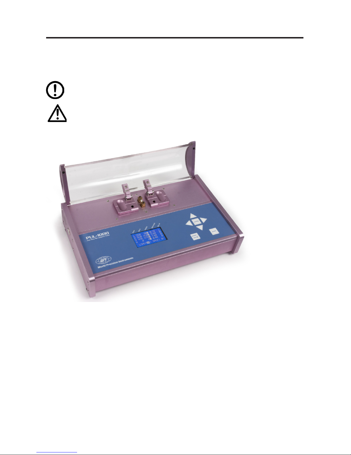
Fig. 1 The PUL-1000 is programmable.
INTRODUCTION
PUL-1000 is a microprocessor controlled, four-stage, horizontal puller for making
glass micropipettes or microelectrodes used in intracellular recording, patch clamp,
microperfusion and microinjection. The puller was designed with tight mechanical
specications and precision electronics for complete control of the pulling process
and accurate reproducibility. It oers programmable sequences of up to four steps
with heating, force, movement and cooling time. This allows graduated cycles for a
variety of applications.
NOTE: This is not a production puller designed for continual Use. If the puller stops in
the middle of a pull, allow time for it to cool down.
Page 6

2 World Precision Instruments
When pulling glass tips ner that 1 um, you should rst wash the glass capillaries in
ltered acetone (or ltered distilled water and ltered 95% alcohol) then allow the
uids to evaporate in a clean dust free environment. This assures that submicron
tips are not immediately clogged with glass particles from the manufacturing of the
capillaries.
A glass capillary is heated by a platinum/iridium lament and pulled by a controlled
force. The PUL-1000 is capable of producing a vast array of pipette shapes.
Pipettes–PUL-1000 can produce pipettes with tip diameters from less than 0.1µm to
10+ µm. Microprocessor settings control the pulling automatically.
Pulling pipettes is an art, and reliable results depend on factors like the operating
environment, the type of glass used and your technique. Understanding how the
puller works is critical to manufacturing the pipettes you want. Glass capillaries
can even be slightly dierent for every lot. Each time you open a new vial of glass
capillaries, recalibrate the puller heat parameters for the new glass.
Programming–The settings for a 4-stage pull may be stored in memory. Up to 95
user-selectable programs can be permanently be stored in memory for later recall.
The instrument contains two factory installed and tested programs. Choose from the
factory installed programs or create your own.
Construction–The cover of the pulling chamber is made with tempered glass to
minimize the eects of humidity and air currents on the reproducibility of pulled
pipettes.
Power Supply–PUL-1000 has a switching power supply for use anywhere in the
world without worry about the line voltage dierences. Pulling reproducibility is
unaected by line voltage uctuation. Heating voltage can be controlled to within 0.1%
accuracy even when line voltage uctuates from 100–240VAC.
Features
• Microprocessor controlled
• Program sequences up to four pulling steps
• Produce micropipettes with a tip diameter less than 0.1µm or greater than 10µm
• Store up to 95 programs in memory
• Two factory programs installed
• Tempered glass cover reduces the eects of humidity and air currents on puller
reproducibility
• Switchable power supply for any line voltage 100–240VAC ensures that line
voltage uctuations don’t aect reproducibility
Parts List
After unpacking, verify that there is no visible damage to the instrument. Verify that all
items are included:
(1) PUL-1000 Puller
(1) TW100-4 - Thin Wall Glass Capillaries, 4 in., 1 / 0.75 OD/ID, package of 500
(1) MF34G-5 package of MicroFil
(1) Instruction Manual
Page 7

PUL-1000
World Precision Instruments 3
Unpacking
Upon receipt of this instrument, make a thorough inspection of the contents and
check for possible damage. Missing cartons or obvious damage to cartons should be
noted on the delivery receipt before signing. Concealed damage should be reported
at once to the carrier and an inspection requested. Please read the section entitled
“Claims and Returns” on page 15 of this manual. Please contact WPI Customer
Service if any parts are missing at 941.371.1003 or customerservice@wpiinc.com.
Returns: Do not return any goods to WPI without obtaining prior approval (RMA
# required) and instructions from WPI’s Returns Department. Goods returned
(unauthorized) by collect freight may be refused. If a return shipment is necessary,
use the original container, if possible. If the original container is not available, use a
suitable substitute that is rigid and of adequate size. Wrap the instrument in paper or
plastic surrounded with at least 100mm (four inches) of shock absorbing material. For
further details, please read the section entitled “Claims and Returns” on page 15 of
this manual.
INSTRUMENT DESCRIPTION
Tempered Glass Lid
Capillary Glass Clamps
V-Shaped Glass Groove
Heating Filament
Carriage
Keypad
LCD Display
Fig. 2 The parts of the puller are identied.
Tempered Glass Lid–For safety, the lid should be closed whenever you are pulling
glass.
Page 8

4 World Precision Instruments
Capillary Glass Clamps–These two clamps securely hold the glass when you are
pulling pipettes.
Heating Filament–The PUL-1000 comes with a platinum/iridium box lament, which
may be easily replaced, as needed. (See “Accessories” on page 10.)
V-Shaped Glass Groove–Slide a single piece of capillary glass into the groove from
one side or the other. The groove helps line up the glass to slide easily through the
lament and hold it in the proper position during pulling.
Carriage–The carriage should move freely. It slides apart as the glass is pulled. Then,
you can manually slide the two ends of the carrier together before the next pull.
LCD Display–This display shows the programming sequence and the dened
parameters. If you press the Stop key on the keypad, you can toggle to the Glass
Capillary Softening Test display.
Fig. 3 The front panel has an intuitive keypad.
Keypad–The keypad has the following keys:
• Arrows–Press the arrow keys to move the cursor in Edit mode. The Up or
Down arrow keys increment or decrement the last digit by 1. Press the Left
and Right arrow keys to increment or decrement the last number by 10. For
example, when you are in Edit mode, you could press the Right arrow to
increase the distance from 0.50 to 0.60 or to increase the force from 200 to
210.
• ENTER– Press to enter or exit the Edit mode.
• START/PAUSE–Press to begin running a pulling program. Press it again to
pause the program.
• STOP–Press to switch between windows or to terminate the pulling program
and return to the main window while the puller is running.
Page 9

PUL-1000
World Precision Instruments 5
Program Sequence
A saved program can be loaded into the PUL-1000 microprocessor. When the LCD
cursor is ashing next to the entry “LOAD”on the display, use the arrows on the
keypad to select a program.
NOTE: The puller is shipped with programs saved in memory locations 00 – 01.
See “Appendix A: Example Sequences” on page 12 for a list of recommended
program setting for WPI glass capillaries. You can start from these settings to get your
own ideal program setting.
For other type of glass capillaries, the rst step is to do a Glass Capillary Softening
Test. (See “Glass Capillary Softening Test” on page 8.) This helps you nd the
required heating power setting for that glass. Then, you can choose a sequence
to match. Finding the right sequence to get the desired glass pipette requires
experimentation.
The table below is provided to show some basic guidelines when setting up a
sequence.
Parameter Increase (↑) Decrease (↓)
Heat Longer Taper Shorter Taper
Force Smaller Tips, Longer Taper Larger Tips, Shorter Taper
Distance Smaller Tips Larger Tips
Delay Shorter Taper Longer Taper
OPERATING INSTRUCTIONS
When heat is applied, and the glass becomes soft, the carriages pull outward, drawing
the tube into a micropipette. A position sensor in the carriage assembly monitors
the movement. When the movement exceeds the programmed distance, the heating
stops.
Load the Glass in the Carriages
The glass capillary is held by clamps mounted on two movable carriages. Both
carriages synchronously slide as a program is executed. Manually slide them back
together when you are loading the glass.
1. To open the clamps, place your thumb under the clamp and depress the release
button with your index nger.
Page 10

6 World Precision Instruments
Set Screw
Filament Block
Release Button
Fig. 4 Press the Release Button to open the clamp.
2. Slide the glass capillary into the V-Shaped Groove from one side. Slide it through
the center of heating lament onto the other side. If you want two equivalent
length micropipettes, be sure to center the glass in the llament.
3. Secure the glass capillary with the clamps.
CAUTION: The carriage has a narrow clearance above the body of the puller. If
foreign material such as broken glass becomes wedged underneath the
carriages, it can cause a bind between the carriage and the body. Remove
foreign material from this area using vacuum only. Use of compressed air may drive
particles deeper, making them more dicult to remove.
Program Run Sequence
The heating element uses a platinum/iridium lament that provides enough heat to
melt all common glasses except quartz. After starting the program, the lament begins
to glow and heats the glass. A solenoid gradually applies a moderate tension to the
glass. The small section of the glass capillary in the lament is heated until it is soft.
When the glass is soft enough, it begins to narrow and stretch longer and thinner. The
carriages moves because of the solenoid’s pulling force, and at some point, the two
halves separate, forming two micropipettes.
Programs
The temperature, tensile force, distance of movement and delay time between steps
are all programmable parameters. Each of these parameters is user-dened for each
step in a four-step sequence. A total of 95 sequences may be stored for recall by
program number. When the unit is powered on, the LCD screen displays the last used
sequence in the window. PUL-1000 is designed to form the pipette in four steps. A
basic program step (called a line) consists of four entries:
Page 11

PUL-1000
World Precision Instruments 7
1. The rst stage is to pull a thin section on the capillary. The heating power, pulling
force and pulling length determine the taper shape and length.
2. The thin section is pulled again in the second stage to reach a preset length.
When the glass capillary is pulled thinner and longer, the waist of pulled section is
proportional to pulled length. The capillary outside diameter is dependent on the
properties of the glass, heating power and pulling force.
3. The third stage is used to control the glass temperature.
4. If necessary, the program repeats until the glass capillary is ready to break. In
the fourth stage, the capillary breaks at a lower temperature to form the tip. The
puller can produce pipettes with tip diameters from less than 0.1mm to tens of
microns.
Program Parameters
Fig. 5 The main display shows the parameters which may be controlled.
For each step of a four-step sequence, the four primary parameters may be set. A
description of each follows:
HEAT–The HEAT parameter determines the amount of heat produced by the lament.
The units represent the amount of current to be passed through the lament. Values
range from 0 to 999. The useful range of values depends upon the lament and glass
type. Usually the value used is close to the value determined in the Glass Capillary
Softening Test (below). During execution of a program line, the puller gradually
establishes a moderate pulling force, and then the lament current is turned on.
CAUTION: DO NOT INCREASE THE HEAT VALUES IN THE PROGRAMS SUPPLIED
WITH THE PULLER UNTIL YOU HAVE READ AND UNDERSTOOD THE SECTIONS
OF THE MANUAL DESCRIBING THE SELECTION OF HEAT VALUES. The use of too
much current can melt the lament, although it will not damage the puller. The
melting point of any type of glass may be determined using a special procedure called
the Glass Capillary Softening Test.
FORCE–The FORCE parameter determines the amount of force delivered to the
carriage by the solenoid. The units are arbitrary (ranging from 50–400g) with the
maximum value set to prevent overheating of the solenoid. The value of the FORCE
determines the solenoid force at the maximum for the pulling stage. The force ramps
from zero to the setting.
NOTE: The force applied may be set as a constant force or a gradient force. The
constant force applies the same amount of force throughout the entire program.
A gradient force allows the force to slowly taper o as the program runs. When the
Page 12

8 World Precision Instruments
force gradually diminishes in the fourth stage, the tip breaks more smoothly. To toggle
between constant and gradient force, move the cursor to the number under force
and press STOP.
DISTANCE–DISTANCE in millimeters (ranging from 0-9.99mm) is the change in
distance between the two movable carriages.
DELAY–DELAY values may range from 0 to 999 and are in units of 0.1 seconds. After
one stage is done, the glass is allowed to cool for the DELAY time before the next
stage begins.
Glass Capillary Softening Test
Run the Softening Test when:
• You change the lament
• Lot numbers or capillary types change
• You create or modify a program
1. Press the STOP key to quit any running program. The following window displays
(Fig. 6).
NOTE: A force of 150g is the factory set value for testing borsilicate glass capillaries
using a 2.5mm square box lament (WPI #13834).
Fig. 6 The window displays when you press the STOP key.
2. Mount a glass capillary on the carriage. See “Load the Glass in the Carriages” on
page 5.
3. Press the START key to run the Glass Capillary Softening Test. The heating power
increases gradually. The heating stops when the glass begins to move.
4. Record the heating power. This is the baseline heating value for the glass type
tested. It is a good starting point for the rst stage of your program.
Page 13

PUL-1000
World Precision Instruments 9
MAINTENANCE
Replacing a Filament
The lament support blocks are located between the two carriages in the middle of
the mechanical unit. The lament clamps are attached to the support blocks. The
lament clamps are held to their supports by set screws. You may adjust the lament
position by loosening the set screw, repositioning the lament and tightening the set
screw.
Filament Support Block
Filament Clamp
Set Screw
Fig. 7 The set screw secures the Filament Clamp to the Filament Support Block.
If the lament wears out or is damaged, it must be replaced. To replace the lament:
1. Loosen the set screws that secures the Filament Clamp on the Filament Support
Block.
2. Remove the old lament or its remaining pieces. Be careful not to drop any material into the mechanical unit.
3. Then, position the new lament and tighten down the set screws. It is best to
approximate the position of the previous lament with the new one. The box
lament should be positioned so that when the glass is clamped it place, it runs
through the center of the box lament. If the lament is not square, or if it is o
center, the glass will not heat evenly.
Glass centered through filament
Correct filament placement
Support
Block
Support
Block
Side View Top View
Wrong filament placement
Fig. 8 Position the lament so the capillary glass runs through the center of the
lament.
Page 14

10 World Precision Instruments
If you are using a lament with a dierent shape or are pulling a dierent diameter
of glass, be sure to test the placement of the glass capillary to verify that it remains in
the center of the lament. When you are pulling larger diameter glass, you will need
a larger lament. Typically, a larger lament has a greater oset from the Filament
Support Block to compensate for the change of the glass position when you are using
glass with a larger diameter.
Choosing a Filament
Appropriate lament selection depends on your research application, but generally
Box Filaments are recommended. This conguration is particularly suitable for slice
preparations where long, parallel walls will aid penetration. If you are using a box
lament, the size of the square box should be approximately 1.0mm to 1.5mm larger
than the outside diameter of the glass to be pulled.
ACCESSORIES
Part Number Description
13834 Replacementboxlament,2.5mmsquare,platinumiridium,2.5mm
wide
14074 Replacementboxlament,3mmsquare,platinumiridium,2mm
wide
SPECIFICATIONS
This unit conforms to the following specications:
Heater Element.......................................................................Platinum/Iridium Filament
Pulling Force...................................................................... (50–400)Solenoid,adjustable
Taper Length......................................................................................................... 1–10mm
Capillary OD Range..........................................................................................1.0–2.0mm
Maximum Capillary Length................................................................................... 170mm
Minimum Capillary Length...................................................................................... 55mm
Permanent Memory Set................................................................................................. 95
AutoShut-oTime....................................................................................................... 90 s
Power Input............................................................................. 100-240VAC1.5A50-60Hz
Power Output................. 19VDCat4.74A(5.5x2.5barrelconnectorwithpositivetip)
Dimensions................................................................................................ 37x24x15cm
Shipping Weight.......................................................................................................... 16lb.
NOTE:Thispullerisdesignedforsinglebarrelborosilicateglassesorpatchglass,
notquartzoraluminosilicate.
Page 15

PUL-1000
World Precision Instruments 11
TROUBLESHOOTING
Issue Possible Cause Solution
Puller stops in the middle
of a pull. Unit beeps.
The unit is over heating Allow the unit time to cool down be-
fore attempting to pull more glass
If program fails in the middle of
a pull, you may have exceeded
the parameters of the unit. For
example, when you add up the
distance of travel for all the stages,
you may have exceeded the maximum range of travel.
Check your program. You may need to
alter the heating or travel parameters
to conform with the unit’s maximums.
New glass doesn’t
pull well
Parameter are not set properly for
the properties of the new glass
Run the Glass Softening Test to establish a new baseline heating parameter.
See “Glass Capillary Softening Test” on
page 8.
Install a new lament. See “Replacing a
Filament” on page 9.
Cannot
select a
program
Puller may be in Edit mode. It will
not execute a program until you
exit the Edit mode.
Press the Exit key to exit the program
editing mode without saving the program. Press Start to run your program.
Unit
Beeps
If program fails to start, carriages
may be too far apart.
Remove the glass, slide the carriages
together and reposition the glass.
NOTE: If you have a problem/issue with that falls outside the denitions of this
troubleshooting section, contact the WPI Technical Support team at 941.371.1003 or
technicalsupport@wpiinc.com.
Page 16

12 World Precision Instruments
APPENDIX A: EXAMPLE SEQUENCES
For WPI single-barrel standard borosilicate glass tubing:
OD: 1.0 mm, WPI # 1B100-4
STEP HEAT FORCE DISTANCE DELAY
1 400 200 2.00 35
2 300 200 0.70 60
3 200 200 0.30 20
4 200 100 0.30 20
OD: 1.14mm (WPI# 4878).
STEP HEAT FORCE DISTANCE DELAY
1 700 350 3.00 55
2 600 100 1.00 60
3 400 200 0.30 25
4 350 120 0.30 20
My Sequences
Name: _____________________________________________
STEP HEAT FORCE DISTANCE DELAY
1
2
3
4
Name: _____________________________________________
STEP HEAT FORCE DISTANCE DELAY
1
2
3
4
Page 17

PUL-1000
World Precision Instruments 13
Name: _____________________________________________
STEP HEAT FORCE DISTANCE DELAY
1
2
3
4
Name: _____________________________________________
STEP HEAT FORCE DISTANCE DELAY
1
2
3
4
Name: _____________________________________________
STEP HEAT FORCE DISTANCE DELAY
1
2
3
4
Name: _____________________________________________
STEP HEAT FORCE DISTANCE DELAY
1
2
3
4
Name: _____________________________________________
STEP HEAT FORCE DISTANCE DELAY
1
2
3
4
Page 18

14 World Precision Instruments
Page 19

PUL-1000
World Precision Instruments 15
* Electrodes, batteries and other consumable parts are warranted for 30 days only from the date on which
the customer receives these items.
WARRANTY
WPI (World Precision Instruments, Inc.) warrants to the original purchaser that this equipment, including
its components and parts, shall be free from defects in material and workmanship for a period of
30 days* from the date of receipt. WPI’s obligation under this warranty shall be limited to repair or
replacement, at WPI’s option, of the equipment or defective components or parts upon receipt thereof
f.o.b. WPI, Sarasota, Florida U.S.A. Return of a repaired instrument shall be f.o.b. Sarasota.
The above warranty is contingent upon normal usage and does not cover products which have been
modied without WPI’s approval or which have been subjected to unusual physical or electrical stress
or on which the original identication marks have been removed or altered. The above warranty will not
apply if adjustment, repair or parts replacement is required because of accident, neglect, misuse, failure
of electric power, air conditioning, humidity control, or causes other than normal and ordinary usage.
To the extent that any of its equipment is furnished by a manufacturer other than WPI, the foregoing
warranty shall be applicable only to the extent of the warranty furnished by such other manufacturer.
This warranty will not apply to appearance terms, such as knobs, handles, dials or the like.
WPI makes no warranty of any kind, express or implied or statutory, including without limitation any
warranties of merchantability and/or tness for a particular purpose. WPI shall not be liable for any
damages, whether direct, indirect, special or consequential arising from a failure of this product to
operate in the manner desired by the user. WPI shall not be liable for any damage to data or property
that may be caused directly or indirectly by use of this product.
Claims and Returns
Inspect all shipments upon receipt. Missing cartons or obvious damage to cartons should be noted on
the delivery receipt before signing. Concealed loss or damage should be reported at once to the carrier
and an inspection requested. All claims for shortage or damage must be made within ten (10) days
after receipt of shipment. Claims for lost shipments must be made within thirty (30) days of receipt of
invoice or other notication of shipment. Please save damaged or pilfered cartons until claim is settled.
In some instances, photographic documentation may be required. Some items are time-sensitive; WPI
assumes no extended warranty or any liability for use beyond the date specied on the container
Do not return any goods to us without obtaining prior approval and instructions from our Returns
Department. Goods returned (unauthorized) by collect freight may be refused. Goods accepted for
restocking will be exchanged or credited to your WPI account. Goods returned which were ordered
by customers in error are subject to a 25% restocking charge. Equipment which was built as a special
order cannot be returned.
Repairs
Contact our Customer Service Department for assistance in the repair of apparatus. Do not return
goods until instructions have been received. Returned items must be securely packed to prevent
further damage in transit. The Customer is responsible for paying shipping expenses, including
adequate insurance on all items returned for repairs. Identication of the item(s) by model number,
name, as well as complete description of the diculties experienced should be written on the repair
purchase order and on a tag attached to the item.
Page 20

USA
International Trade Center, 175 Sarasota Center Blvd., Sarasota FL 34240-9258
Tel: 941-371-1003 • Fax: 941-377-5428 • E-mail: sales@wpiinc.com
UK
1 Hunting Gate, Hitchin, Hertfordshire SG4 0TJ
Tel: 44 (0)1462 424700 • Fax: 44 (0)1462 424701 • E-mail: wpiuk@wpi-europe.com
Germany
Saarstraße 23, D-61169 Friedberg (Hesson), Germany
Tel: +49 (0)6031 1602171 • Fax: +49 (0)6031 1602180 • E-mail: wpide@wpi-europe.com
China & Hong Kong
WPI Shanghai Trading Co., Ltd.
Rm 25e, No8 Dongfang Rd., Pudong District, Shanghai, 200120 PR China
Tel: +86 21 6888 5517 • E-mail:chinasales@china.wpiinc.com
Brazil
Av. Conselheiro Nébias, 756 sala 2611, Santos-CEP: 11045-002, São Paulo Brazil Tel: (013) 406-
29703 • E-mail: info@brazil.wpiinc.com
Internet
www.wpiinc.com • www.wpi-europe.com • www.wpiinc.cn • www.wpibrasil.com.br
 Loading...