

Page 1

EVOM2
Epithelial Voltohmmeter
Serial No._____________________
Instrumenting scientific ideas
WORLD
PRECISION
INSTRUMENTS
www.wpiinc.com
INSTRUCTION MANUAL
082318
Page 2

Page 3

EVOM2
CONTENTS
ABOUT THIS MANUAL ................................................................................................................... 1
INTRODUCTION .............................................................................................................................. 1
QUICK REFERENCE ......................................................................................................................... 2
For Resistance Measurements: ....................................................................................... 2
For Voltage Measurements:.............................................................................................. 2
INSTRUMENT DESCRIPTION ........................................................................................................ 2
Parts List ...................................................................................................................................... 2
Unpacking ................................................................................................................................... 3
Set-up ........................................................................................................................................... 3
Test Resistor ......................................................................................................................... 3
STX2 Electrode ..................................................................................................................... 3
Meter ...................................................................................................................................... 3
Instrument Diagnostics .......................................................................................................... 5
Testing the EVOM2 Meter ................................................................................................. 5
OPERATING INSTRUCTIONS ....................................................................................................... 5
Positioning Electrode in a Culture Cup ................................................................................ 5
Making Resistance Measurements ....................................................................................... 7
Making Voltage Measurements ............................................................................................. 7
MAINTENANCE ................................................................................................................................ 8
Cleaning the STX2 Electrode .................................................................................................. 8
Disinfecting the STX Electrode ............................................................................................... 9
Sterilizing the STX2 Electrode ................................................................................................ 9
Resurfacing the Electrode .....................................................................................................10
Storing of the Electrode ........................................................................................................10
EVOM2 Charger and Battery ................................................................................................ 10
Changing the Battery Pack ....................................................................................................11
ACCESSORIES.................................................................................................................................13
TROUBLESHOOTING ...................................................................................................................14
EVOM2 Meter ...........................................................................................................................14
STX2 Electrode ......................................................................................................................... 14
SPECIFICATIONS ............................................................................................................................ 18
APPENDIX A: RESISTANCE CALCULATIONS ............................................................................ 18
Resistance ................................................................................................................................. 18
Resistance Value of the “Blank” Insert ...............................................................................19
Unit Area Resistance .............................................................................................................. 19
APPENDIX B: 24 MM DIAMETER (6-WELL) INSERTS AND STX ELECTRODES ................ 20
APPENDIX C: IMPROVING THE ACCURACY AND REPEATABILITY OF THE SYSTEM ...... 20
Copyright © 2018 by World Precision Instruments. All rights reserved. No part of this publication may
be reproduced or translated into any language, in any form, without prior written permission of World
Precision Instruments, Inc.
Page 4

DECLARATION OF CONFORMITY .............................................................................................. 22
WARRANTY .....................................................................................................................................23
Claims and Returns ................................................................................................................23
Page 5
EVOM2
WORLD PRECISION INSTRUMENTS 1
ABOUT THIS MANUAL
The following symbols are used in this guide:
This symbol indicates a CAUTION. Cautions warn against actions that can
cause damage to equipment. Please read these carefully.
This symbol indicates a WARNING. Warnings alert you to actions that can
cause personal injury or pose a physical threat. Please read these carefully.
NOTES and TIPS contain helpful information.
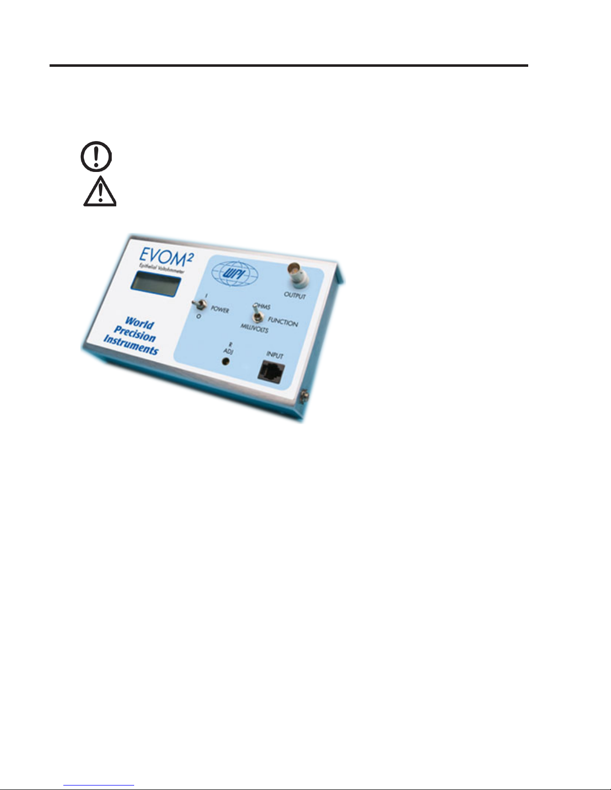
Fig. 1–The EVOM2 measures resistance or voltage across a tissue membrane.
INTRODUCTION
EVOM was the rst instrument designed to perform routine Trans Epithelial Electrical
Resistance (TEER) measurement in tissue culture research. EVOM2 is the next
generation. The conuence of the cellular monolayer is determined by an increase in
TEER detected using the unique electronic circuit of the EVOM2 and STX2 electrode
(included with the instrument). The EVOM2 qualitatively measures cell monolayer
health and quantitatively measures cell conuence. When combined with WPI’s
Endohm chamber, the EVOM2 can also be used to perform trans endothelial electrical
resistance measurement.
The EVOM2 produces an AC current that avoids electrode metal deposits and adverse
eects on tissues, which can otherwise be caused by a DC current. In addition,
resistance readings are unaected by membrane capacitance and membrane voltage.
EVOM2 is designed with an internal rechargeable 6V NiMH 2700mAH battery pack.
The unit is supplied with an external battery charger. A fully-charged battery pack will
provide about eight hours of running time. When the battery power falls below the
nominal threshold, the meter automatically powers o. While the meter operates
safely when it is plugged into an AC power source, WPI recommends disconnecting
the meter from the charger when it is in use. Doing so provides for the maximum
electrical isolation and reduces the noise to ensure readings of the highest accuracy.
Page 6

2 WORLD PRECISION INSTRUMENTS
For automation of TEER measurement, consider WPI’s REMS AutoSampler (WPI
# REMS), which includes the robotic sampler, data acquisition board, base plate,
Windows
®
based software and an electrode for either the 24- or 96-well plate.
QUICK REFERENCE
For complete instructions on performing measurements with the EVOM2, see
"OPERATING INSTRUCTIONS" on page 5
For Resistance Measurements:
1. Disconnect the EVOM2 from the charge and turn the Power on (I).
2. Sterilize the electrode.
3. Connect the electrode to the meter.
4. Precondition the electrode in growth media.
5. Set the Function switch to Ohms.
6. Measure the blank resistance and record the value.
7. Perform the measurements. To obtain the actual tissue reading, subtract the
blank resistance value.
8. Clean, dry and store the electrode.
For Voltage Measurements:
1. Sterilize the electrode.
2. Connect the electrodes to the EVOM2 and leave the power o.
3. Equilibrate the electrode in growth media with the EVOM2 power o and the
Function switch set to Ohms.
NOTE: Electrode tips must be immersed in solution to equilibrate.
4. Disconnect the EVOM2 from the charger and set the Function switch to Millivolts.
5. Turn the Power on (I).
6. Measure the blank voltage and record the value.
7. Make your voltage measurements across the membranes you are testing. To
obtain the actual tissue reading, subtract the blank voltage value.
8. Clean, dry and store the electrode.
INSTRUMENT DESCRIPTION
Parts List
(1) EVOM2 meter
(1) STX2 electrode set
(1) 91750 1000W test resistor
(1) 600-grade ultra-ne sandpaper
(1) A/C power cord and charger
(1) Instruction Manual
Page 7
EVOM2
WORLD PRECISION INSTRUMENTS 3
Unpacking
Upon receipt of this instrument, make a thorough inspection of the contents and
check for possible damage. Missing cartons or obvious damage to cartons should be
noted on the delivery receipt before signing. Concealed loss or damage should be
reported at once to the carrier and an inspection requested. Please read the section
entitled “Claims and Returns” on page 23 of this manual. Please call WPI Customer
Service if any parts are missing.
Returns: Do not return any goods to WPI without obtaining prior approval (RMA
# required) and instructions from WPI’s Returns Department. Goods returned
(unauthorized) by collect freight may be refused. If a return shipment is necessary, use
the original container. If the original container is not available, use a suitable substitute
that is rigid and of adequate size. Wrap the instrument in paper or plastic surrounded
with at least 100mm (four inches) of shock absorbing material. Please read the section
entitled “Claims and Returns” on page 23 of this manual.
Set-up
Test Resistor
The 1000W test resistor (WPI #91750) is shown in Fig. 2. See
"Testing the EVOM2 Meter" on page 5 for instructions on using the test resistor.
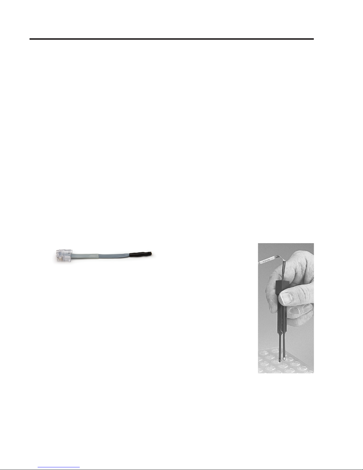
Fig. 2–1000W Test resistor
STX2 Electrode
For resistance measurements only, the STX2 electrode can be used
directly from dry storage without preconditioning. The STX2
electrode (Fig. 3) incorporates a xed pair of probes, 4mm wide
and 1mm thick. Each probe has an outer and an inner electrode.
(See Fig. 4 on page 4) The outside electrodes are small silver
(Ag) pads that pass current through the membrane sample. They
are referred to as current electrodes. The inner electrodes are
small Ag/AgCl pellet voltage sensors. They are referred to as
voltage electrodes.
Fig. 3–(Right) STX2 electrode
Meter
The EVOM2 is ready to use, but you will need a slot-head screwdriver (not included) to
calibrate the R ADJ screw.
Page 8
4 WORLD PRECISION INSTRUMENTS
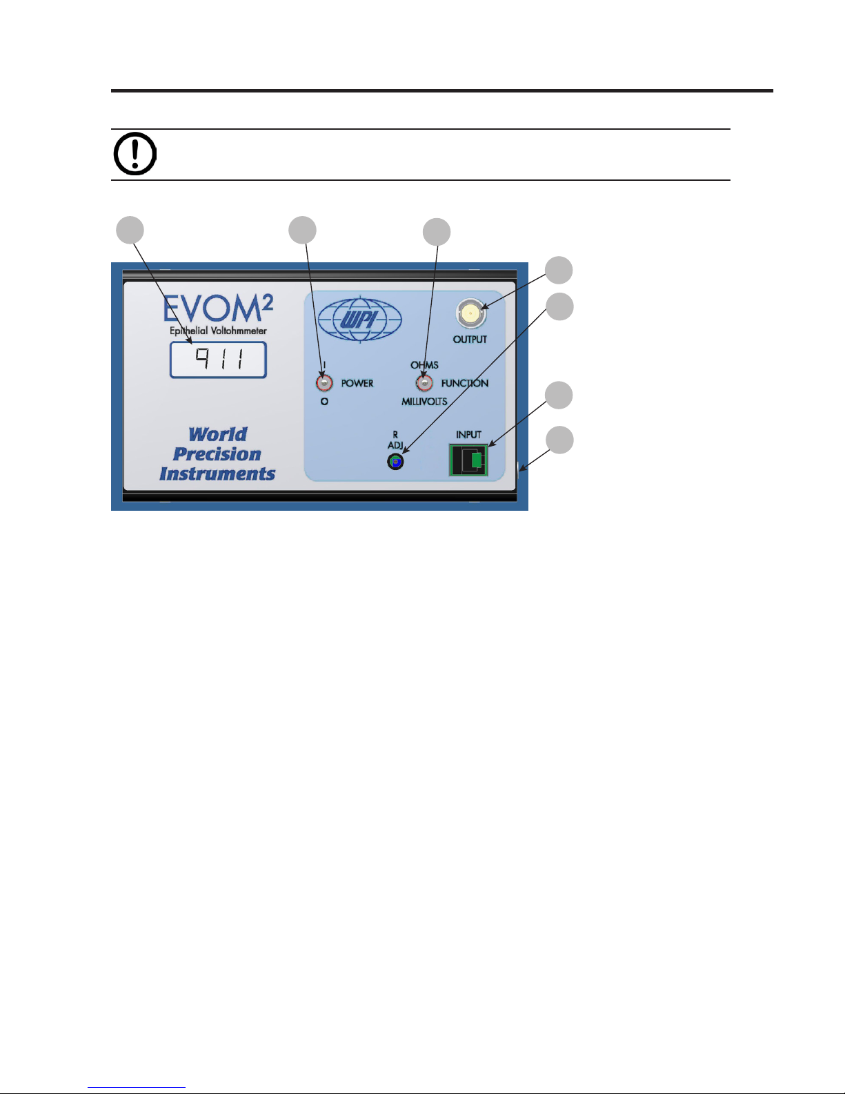
CAUTION: Do not leave the meter in direct sunlight for extended periods of
time. The LCD display will become dark and unreadable.
Labeled items on Fig. 3 are described below.
1
Digital LCD Display
4 Analog Output
3
Function Switch
2
Power Switch
5 R ADJ Calibration
6 Input Port
7 Charger Input Jack
Fig. 4–EVOM2 meter
Digital LCD Display: The Digital LCD Display registers readings of four and a
half digits. When the meter is measuring voltage, it displays the potential dierence
between the two electrodes in millivolts (mV) up to 199.9mV. When the meter is
measuring resistance, it displays the resistance between the two electrode probes
in ohms (W). Although the meter will provide readings up to 13,000W, the accuracy
specication is only guaranteed up to 10,000W.
Power Switch I/O: The toggle switch turns the meter on (I) and o (O).
Function Switch (Ohms/Millivolts): When in the Ohms position, the meter is in
the resistance measuring mode. When in the Millivolts position, the meter is in the
voltage measuring mode.
Analog Output: This standard BNC connection allows for output of analog data to
a recording device.
R ADJ Calibration Screw: When the 1000W test resistor is inserted into the input port,
this screw is used to calibrate the meter display to 1000W while in the Ohms mode.
Input Port: Insert the RJ-11 plug of the test resistor, STX2, STX3 or Endohm into
this port to connect it to the meter.
Charger Input Jack: Insert the charger connector into the Charger Jack and plug
the other end into a standard wall outlet to charge the EVOM2 battery pack. Do NOT
take resistance or voltage measurement with the charger connected.
Page 9
EVOM2
WORLD PRECISION INSTRUMENTS 5
Instrument Diagnostics
It is recommended that EVOM2 be put through the diagnostics described below
before using it for the rst time and then periodically thereafter. If there is a concern
that the meter or the electrode is not functioning properly, the following protocols
may be used to conrm EVOM2’s operating status.
Testing the EVOM2 Meter
1. Insert the RJ-11 plug at the end of the test resistor (Fig. 2) into the Input port on
the meter.
2. Set the Function Switch to Ohms.
3. Disconnect the EVOM2 from the charger and turn the Power on (I). The meter
should display 1000W. If not, adjust the R ADJ screw with a small slot-head screwdriver until the meter shows a reading of 1000W.
OPERATING INSTRUCTIONS
Before making any measurements, charge the EVOM2 overnight. Allow the unit to
warm up for 20 minutes before making any measurements.
Positioning Electrode in a Culture Cup
Proper placement of the electrode in the cell is critical to making accurate
measurements. The STX2 electrode is designed to facilitate measurements of
membrane voltage and resistance of cultured epithelia in tissue culture wells. The
lengths of the electrodes are unequal allowing the longer (external) electrode to
touch the bottom of the dish containing the external culture media while preventing
the shorter (internal electrode) from reaching the bottom of the tissue culture cup
or insert (see Fig. 5). This feature ensures proper positioning between the electrode
and the cell layer in the cup during the trans membrane measurement. In addition,
by positioning the longer tip so that it touches the bottom of the dish each time, the
reproducibility of the measurements is signicantly improved.
Fig. 5–Electrodes in solution
Page 10

6 WORLD PRECISION INSTRUMENTS
Place the electrode into the well so the tips just touch the bottom of the wells without
exing the electrode. See Fig. 6. Variance of the angle (Fig. 7) or depth of immersion
(Fig. 8) of the electrode will aect resistance measurements.
Fig. 6–(Left) Correct placement
Fig. 7–(Center) Angle variance
Fig. 8–(Right) Depth variance
NOTE: To obtain reproducible results in the same cup, the position of the
electrodes must remain constant. To improve the reproducibility and stability of the
measurement, it is important to steady the electrode while measuring. You may either
touch or hover, but for consistent results, you must use the same methodology each
time.
CAUTION: When moving the electrodes from one sample cup to another, it is
best not to rinse the electrodes with distilled water. Silver/silver chloride
electrodes may take several minutes to recover from exposure to distilled water,
during which time the potential may drift by a few millivolts. If it is necessary to
wash the electrodes between measurements to avoid carryover of one sample into the
next, the electrodes should be rinsed with the experimental culture media.
TIP: Transwell inserts made by Corning Costar, in general, have a greater distance
between the bottom of the lter cup and the bottom
of the plate (Fig. 5). This gap also varies from one lot
to the other. It may be large enough to cause the
shorter internal electrode to hit the cell layer when
the longer electrode touches the bottom of the dish.
In this case, the Transwell user can use the optional
STX3 electrodes instead of the STX2. They are
adjustable. Or, Transwell users can sand 0.5mm o
the shorter probe. See the image at the right. Place
the 600-grade sand paper on the edge of a table,
and holding the electrodes vertically with the tip of
the shorter electrode against the sandpaper and the
longer electrode hanging over the edge of the table,
drag the electrode lightly over the sandpaper. Check
the tip of the electrode, and repeat this procedure
until the electrode is the proper length.
Fig. 9–(Right) Sanding STX2 electrode
Page 11

EVOM2
WORLD PRECISION INSTRUMENTS 7
CAUTION: Only the green body of the STX2 electrode should be sanded. DO
NOT SAND ANY METAL PART of the electrode or damage to the electrode will
result.
Making Resistance Measurements
When the EVOM2 is used for resistance measurements only, the electrode does not
need to be equilibrated or preconditioned before use. Any galvanic voltage asymmetry
present on the measurement electrode is cancelled by the EVOM2 circuitry.
1. Disconnect the EVOM2 from the charger.
2. Connect the electrode to the meter. Insert the RJ plug at the end of the exible
electrode cable into the Input port on the meter.
3. Place the electrode in your culture medium for a few minutes.
4. To make resistance measurements, set the Function switch to Ohms. Disconnect
the EVOM2 from the charger and turn the Power on (I).
5. To measure the blank resistance, place the electrode in a blank culture cup lled
with electrolyte (for example, the cell culture insert without cells). See "Positioning Electrode in a Culture Cup" on page 5. Insert the electrode into the blank
cup. A steady ohms reading of the solution resistance should result. The value of
the blank always adds to the total resistance measured across a tissue culture
membrane. See "APPENDIX A: RESISTANCE CALCULATIONS" on page 18 for a
more detailed discussion of the source of the blank resistance and information
on calculating true tissue resistance and unit area resistance (the value that is
normally reported).
NOTE: The blank resistance must be measured and then subtracted from the
resistance reading across tissue in order to obtain the true tissue resistance.
6. Make your experimental resistance measurements. Subtract the blank resistance
to obtain the true resistance value of your cultured cell monolayers.
7. When you nish making measurements, clean and store your electrodes dry. See
"Cleaning the STX2 Electrode" on page 8.
Making Voltage Measurements
1. Disconnect the EVOM2 from the charger.
2. Connect the electrode to the meter. Insert the RJ plug at the end of the exible
electrode cable into the Input port on the meter.
3. For voltage measurements, the electrodes should be equilibrated to eliminate any
galvanic oset before use. To assure voltage stability and a low inter-electrode
potential dierence, turn the Power o (O) on the EVOM2 and immerse the
electrode in electrolyte solution (for example, 0.1 – 0.15M KCl) with the electrodes
Page 12

8 WORLD PRECISION INSTRUMENTS
connected to the EVOM2. The STX2 voltage electrode pairs are shorted together
when they are connected to the instrument and the Power is o (O). With the
voltage electrode connector pins short-circuited for several hours, the asymmetri-
cal potential dierence across the two voltage electrodes is reduced. The inter-
electrode DC potential will be a few millivolts or less and quite stable.
4. First, measure the voltage of the electrodes in growth media (or electrolyte) by
following this sequence:
A. Set the Function switch to Millivolts. This prevents current from being ap-
plied as it does in the Ohms mode.
B. Then, disconnect the EVOM2 from the charger. Ensure the galvanic charge
on the voltage electrode has been minimized. Then, turn the Power on (I).
C. Insert an equilibrated electrode into the cell culture insert. A steady voltage
reading of the trans membrane potential should result.
NOTE: The shorter (internal) electrode is connected to instrument ground and acts
as the reference electrode. If the meter reading is positive in the Millivolts mode, the
basal side of the cellular tissue (the side adhering to the lter of the insert) is positive
with respect to apical side (exposed). Conversely, if the meter is reading negative, it
means that the basal side is negative with respect to the apical side.
5. If the voltage value is of your growth media greater than a 20mV, equilibrate your
electrode again by soaking it in 100mM KCl for 12–24 hours while the electrode
is connected to the EVOM2. Set the Function switch to Ohms, and power o the
meter. After equilibration, set the Function switch to Millivolts. Then, turn the
meter on again and repeat step 5.
6. Make your experimental voltage measurements. Add or subtract the voltage of
your growth media measured in step 5 to obtain the true voltage value of your
cultured cell monolayers.
MAINTENANCE
Electrodes must be properly cleaned, sterilized and stored.
CAUTION: Do not ame electrodes. Doing so will cause them to melt.
Cleaning the STX2 Electrode
With use, the electrode surface can become coated with protein or other foreign
materials. This build-up, or contamination, can degrade the performance of the
system. After every use, rinse the STX electrodes with distilled water and store them
dry. Periodically clean your STX electrodes with Tergazyme, a proteolytic detergent
manufactured by Alconox.
1. Rinse with the electrodes with distilled water and dry them.
Page 13

EVOM2
WORLD PRECISION INSTRUMENTS 9
2. Make a 1% solution of Tergazyme according to the manufacturer's instructions.
3. Suspend the tips of the electrodes in the Tergazyme solution, with the exposed
electrode surfaces fully immersed. During soaking, the surfaces of the electrodes
may be brushed with a soft brush (like a tooth brush), if desired. The soaking time
varies according to your maintenance schedule and the frequency of your cleaning.
• Soak overnight when electrodes have not been on a routine maintenance
cleaning schedule.
• Soak 30–60 minutes if you are on a weekly cleaning schedule.
• Soak 5 minutes if you clean your electrodes daily.
4. Rinse well with distilled or de-ionized water. Allow them to air dry and store the
electrodes dry away from exposure to sunlight.
Disinfecting the STX Electrode
The STX electrodes are resistant to most methods of low temperature chemical
disinfection. A solution of 5% sodium hypochlorite (undiluted household bleach) is a
good choice. Ortho-phthaladehyde (Cidex OPA or Rapicide OPA), ethanol or isopropyl
alcohol are also acceptable.
CAUTION: NEVER leave the electrode in alcohol for more than 30 minutes at
a time. Continuously soaking the electrode in alcohol will weaken the
protective coating on the electrode and shorten its life.
CAUTION: Ammonia is NOT recommended, because the silver chloride
electrodes dissolve in ammonia.
Sterilizing the STX2 Electrode
The STX2 electrodes are non-sterile as supplied. Acceptable low temperature
sterilization methods for the electrodes include gamma irradiation, hydrogen peroxide
plasma and ethylene oxide gas (ETO).
CAUTION: Do NOT autoclave the electrode.
CAUTION: Do NOT expose the electrodes to ultra-violet light, because UV
light decomposes silver/silver chloride electrodes.
Page 14

10 WORLD PRECISION INSTRUMENTS
Resurfacing the Electrode
To resurface the electrode, lightly sand the voltage electrode
of the STX2, which is the silver pellet on the inner surface
near the electrode tips. Use the 600-grade ultra ne
sandpaper provided. (See Fig. 9, right.) Remove only a very
thin surface layer of the pellet.
Fig. 10–(Right) Use caution when you are sanding electrodes.
CAUTION: Repeated sanding will eventually wear
down the Ag/AgCl pellets. When sanding no longer
improves the voltage readings, the electrode needs
to be replaced.
TIP: In the absence of 600-grade sandpaper, an ink eraser
may be substituted to clean the electrodes.
Storing of the Electrode
Short term storage (overnight): Immerse the electrode tip in electrolyte solution.
Ensure the electrode cable plug is connected to the electrode port on the EVOM2
meter and the meter is turned o, so that the system is short-circuited. This serves to
maintain electrochemical symmetry.
Long term storage: When storing electrodes, rinse the electrode with distilled water
and store it dry and in the dark.
EVOM2 Charger and Battery
Charge the batteries monthly. Charge the unit overnight with the power switch turned
o.
CAUTION: To avoid damage to the battery pack, make sure the EVOM2 is
powered o when charging the battery.
The EVOM2 charger plugs into a standard AC wall outlet for recharging the battery
pack. It incorporates a universal power supply allowing for use in many countries. The
EVOM2 contains a NiMH 6V 2700mAH rechargeable battery pack.
When the battery charge gets low, "BATT" appears in the digital display. To protect the
battery, an automatic power down circuit is used when the battery charge gets too
low. To avoid an automatic power down, recharge the battery when the BATT warning
appears.
STX2
sand lightly
NO
sanding
!
NO
sanding!
Page 15

EVOM2
WORLD PRECISION INSTRUMENTS 11
Changing the Battery Pack
The battery pack can be repeatedly charged and
discharged for approximately 500 cycles. It may be
charged at any time in the discharge cycle, and can be
charged continuously without damage.
CAUTION: Use ONLY the EVOM2 charger. Use of
any other charger may damage the battery pack.
Fig. 11–NiMH replacement battery pack
The battery life is about 1 to 2 years, depending upon use. NiMH batteries discharge
even if they are not being used. The rate of discharge is related to temperature. The
cooler the temperature, the slower the discharge rate. If the battery pack is allowed
to self discharge for too long, damage may result. To prevent battery damage, charge
the battery pack at least once every two months. Should the battery pack fail in your
EVOM2, replacements are available (WPI #91736). See "ACCESSORIES" on page 13.
To change the battery pack:
1. Using a #1 Phillips screwdriver, remove the four screws from the EVOM2 case.
2. The battery pack is mounted on the bottom chassis plate. Using a #1 Phillips
screwdriver, remove the two screws securing the battery pack cover.
Fig. 12–Battery pack mounted to bottom chassis plate of EVOM2
3. Disconnect the small plastic connector by pulling it straight up at the circuit board
(Fig. 13). Note the position of the connector and wire color code.
4. Properly dispose of the used battery pack.
5. The battery pack connector will only install on the circuit board one way. If it does
not slide easily into place, do not force it. To install the battery pack, line up the
locking guide on the circuit board with the tabs on the connector. The locking
guide must face the latching ledge (Fig. 13). Slide the connector over the pins on
the board and push the connector straight down.
WARNING: DO NOT REVERSE POLARITY WHEN CONNECTING THE
BATTERY PACK. PERSONAL AND EQUIPMENT DAMAGE MAY RESULT.
Page 16

12 WORLD PRECISION INSTRUMENTS
Latching Ledge
Latching Ledge
Locking Guide
Locking Guide
Fig. 13–Battery pack connector locked in place
6. Position the battery pack in the chassis so that the wires are routed under the
aluminum clamp and towards the center of the chassis. Re-secure the battery
pack cover with the two Phillips screws.
CAUTION: Before you reassemble the case, verify that no bare wires touch
the metal chassis.
7. Reassemble the EVOM2 case.
8. Charge the new battery pack for at least 24 hours.
Page 17

EVOM2
WORLD PRECISION INSTRUMENTS 13
ACCESSORIES
WPI Part # Description
REPLACEMENT PARTS
STX2 Replacement Electrode Set
METER ACCESSORIES
3993 Electrode Adapter (for electrodes with 2mm pins)
2851 BNC cable, 6-ft
800496 Battery Charger
91736 NiMH Rechargeable Battery Pack
91750 1000W Test Resistor
ELECTRODES FOR TEER (EPITHELIAL) MEASUREMENT
STX2 Replacement Electrode Set
STX3 Adjustable Electrode Set
ELECTRODES FOR ENDOTHELIAL/EPITHELIAL MEASUREMENT
ENDOHM-6 Endohm for 6 mm culture cup (24 wells per plate) and the
12 mm Millicell-CM
ENDOHM-12 Endohm for 12 mm culture cup (12 wells per plate)
ENDOHM-24SNAP Endohm for 24 mm and Costar Snapwell cup (6 wells per
plate)
ELECTRODES FOR HTS (High-Throughput) ENDOTHELIAL MEASUREMENT
STX100C STX100 for Corning Costar HTS Transwell-24
STX100M STX100 for Millipore Multiscreen CaCo 96-Well Plate
STX100C96 STX100 for Corning HTS 96-Well Plate
OTHER
7364-4 Cidex OPA
504611 Rapicide OPA/28
LAB-TRAX-4 4-Channel Data Acquisition System
Electrode Adapter (WPI# 3993) converts the four contacts in the RJ-11 into four
independent 2-mm jack. It allows the user to utilize the EVOM2 meter with another
four-electrode system.
STX2 is the standard electrode for use with the EVOM2 and is designed to facilitate
measurements of membrane voltage and resistance (TEER) of cultured epithelia directly
in tissue culture wells. The electrode incorporates a xed pair of probes, 4mm wide and
1mm in thickness. Each probe has an outer (voltage) and an inner (current) electrode.
STX3 is an alternative electrode to the STX2 that can be used with the EVOM2. It
diers from the STX2 in that the vertical distance between the probes of the STX3 can
be adjusted.
STX100C and STX100F are optional electrodes for use with the EVOM2. These
electrodes have a smaller form factor specically designed for high throughput
screening (HTS) plates with higher well counts. The shape of the STX100 electrode is
keyed to the access ports of the well plate. This results in consistent spatial positioning
leading to superior reproducibility from well to well.
Page 18

14 WORLD PRECISION INSTRUMENTS
Endohms are is an optional electrode chambers for the EVOM2 that may be used
when working with well cups that are individually removable. It can also be used
for studying the tight junction changes induced by chemicals and other factors.
Concentric pairs of electrodes above and below the insert membrane results in
excellent stability and reproducibility. (See "APPENDIX C: Improving the Accuracy and
Repeatability of the System" on page 20.) Unlike the STX2, the inserts must be
transferred from the culture plate to the Endohm chamber to make a measurement.
TROUBLESHOOTING
EVOM2 Meter
Most of the time, system problems are related to the electrode, not the meter itself.
At least half of the meter failures result from a failed switch because of the presence
of corrosion, and typically corrosion is caused by accidental spillage of saline solution
or culture media on the meter. If the meter has been kept free of salt solution and
functional testing of the meter demonstrates acceptable performance results, then
the meter is working correctly. (See "Testing the EVOM2 Meter" on page 5.)
STX2 Electrode
Although the STX2 electrode is warranted for 30 days, its normal life is 1 to 2 years,
depending on its usage. Some issues you may encounter include:
• UNSTABLE OR HIGH VOLTAGE READING: If the electrode fails, the most common
symptom is an unstable or unusually high reading.
• LOW RESISTANCE: When the meter displays a lower than expected resistance, but
is stable and reproducible, the most likely cause is related to the cell culture, not
the electrode or meter.
NOTE: Cleaning the electrode often corrects most of these issues. See "Cleaning the
STX2 Electrode" on page 8.
While there is no quantitative method available to do an in situ or wet test on the
electrode, this method helps you determine if the electrode is working and will
respond to an increase in resistance. Test the resistance dierences between a well
lled with electrolyte and a blank culture insert lled with electrolyte. The resistance
of electrolyte alone should be less than 50W and stable, if the electrode is kept
stationary. The resistance of the blank insert is normally in the 80 to 200W range,
depending on the brand and size.
TIP: During normal usage, it is helpful to write down the resistance range of each
particular type of blank insert with the specic culture media used. If the electrode
is subsequently suspected of having a problem, a comparison of current readings to
past readings on the same blank insert and culture media could assist in determining
if the electrode is functioning as expected.
Page 19

EVOM2
WORLD PRECISION INSTRUMENTS 15
Issue Possible Cause Solution
Unit runs
briey, and
powers o
Unit is insu-
ciently charged
Recharge the unit for at least 12 hours.
NOTE: Make sure the EVOM2 is powered o when
charging the battery.
Unit does not charge
Insecure connection at power
input jack on
meter
Verify that the power connector is securely connected
at the meter power input jack.
Defective charger Verify correct output voltage at the power supply con-
nector with a volt meter. Replace the power supply if
approximately +12V DC is not present at the center
conductor on the connector. If the charger is working
and the unit does not power up, contact WPI for service.
Meter will not power on
with charger DISCON-
NECTED
Batteries are
discharged
The meter powers down automatically when the bat-
teries are depleted. Power o the meter and connect it
to the battery charger. Charge it for at least 12 hours.
A full charge may require up to 24 hours. For reliability,
the meter should be charged each evening (with the
power o) before use the next day.
Batteries are
defective
Replace the battery pack or contact WPI for service. See
"Changing the Battery Pack" on page 11.
Voltage reading is unstable
Electrodes are
heavily charged
or dirty
Clean the electrodes. See "Cleaning the STX2 Electrode"
on page 8.
Electrode too
close to strong
electromagnetic
radiation device
Move the system to a dierent area away from sources
of electromagnetic elds. Electromagnetic eld sources
could include computers, MRI equipment, magnetic stirrers, etc. Cell phone signals can also interfere.
Power line or
output jack
connected to a
recording device
causing noise
Remove the connection to the recording device to
eliminate the possibility of a ground loop.
Page 20

16 WORLD PRECISION INSTRUMENTS
Issue Possible Cause Solution
Voltage reading is not zero in plain
culture media or blank cell
Electrode not
equilibrated
The Ag/AgCl disks (inner voltage measurement electrodes)
on the probe may become polarized due to an uneven
distribution of ions between the electrode pair. This ionic
charge can be neutralized by immersing the probe into
0.1M KCL for 24 hours with the probe electrodes shorted
electrically. The probe is shorted electrically when it is
connected to the meter with the power OFF, and the
FUNCTION switch in the OHMS position.
Dirty electrode Clean the electrode. (See “"Resurfacing the Electrode"
on page 10.)
Conductive
contamination
between electrodes
Inspect the inter-electrode surface areas for material
which could form a conductive bridge between the
inner and outer electrodes. If the material cannot be
removed, the electrode should be replaced.
Corrosion has
formed on conductive traces
An insulative transparent coating protects the copper
conductors that connect each electrode to the main
wiring in the handle. When the probe is very old, this
coating can deteriorate, allowing the salts in the media
solution to leech through to the copper conductors.
This is observed as a black discoloration on the copper
circuit traces underneath the conformal coating. If this
is observed, replace the electrode.
Resistance
reading unusu-
ally high
Contaminated
electrode contacts
With use, the chopstick electrode probe contacts may
acquire a buildup of protein or other foreign material
that eectively increases the baseline resistance of the
electrodes. The electrodes can be cleaned using various
methods. See "Cleaning the STX2 Electrode" on page
8.
Resistance reading
unusually low
Cell culture or
media problem
If the cell culture has been given sucient time to achieve
conuence, and the reading is stable but signicantly
lower than expected, then the problem is probably related
to the cell culture. Electrode failure will not generally cause
a lower than expected yet stable reading. Use the test
resistor to verify the meter is functioning correctly. The
meter display should read 1000W. Refer to the appropriate electrode manual for instructions on testing the
electrode.
Page 21

EVOM2
WORLD PRECISION INSTRUMENTS 17
Issue Possible Cause Solution
Resistance is a
negative value
Conductive
contamination on
electrodes
Use the 1000W test resistor to verify that the meter is
working correctly. The meter display should show 1000W.
If a negative value exists only when using the STX electrode, inspect the electrode for the possible formation
of a conductive bridge of foreign material that electrically
joins the current and voltage electrodes. Remove the
foreign material and retest.
Resistance reading drifts or is unstable
Electrodes are
not immersed
in culture media
solution
Use the test resistor to verify that the meter is functioning correctly. The meter display should read 1000W. The
meter will not provide a stable reading if the electrodes
are disconnected from the meter or if the electrodes
are not immersed into culture media.
Electrodes are
not held still during measurement
Use the test resistor to verify the meter is functioning
correctly. The meter display should read 1000W. Handheld electrodes must be kept as motionless as possible
during a measurement. Excessive movement will cause
the measurement to uctuate.
Charger is
connected to the
meter
The meter reading can become unstable due to the loss
of electrical isolation when the charger is connected to
the AC power. To ensure stability of readings, always
disconnect the charger from the meter when making
measurements.
Meter needs set Use the R ADJ calibration screw on the front panel to
adjust the resistance value to 1000W, using the test
resistor. See "Testing the EVOM2 Meter" on page 5.
Resistance read-
ing drifts or is
unstable
Old electrode
probe
Use the test resistor to verify the meter is functioning
correctly. The meter display should read 1000W. The
lifetime of the chopstick electrodes is between 1- 2
years with normal use.
NOTE: If you have a problem/issue with your EVOM2 that falls outside the denitions
of this troubleshooting section, contact the WPI Technical Support team at
941.371.1003 or technicalsupport@wpiinc.com.
Page 22

18 WORLD PRECISION INSTRUMENTS
SPECIFICATIONS
Membrane Voltage Range ............................................................................................ ±200.0 mV
Resolution ................................................................................................................................. 0.1mV
Resistance Range ........................................................................................................... 0 to 9999W
Resistance Resolution .................................................................................................................1W
AC Square Wave Current ...................................................................±10µA nominal at 12.5Hz
Power .........................................................Internal rechargeable 6V NiMH 2700mAH battery
................................................................................ with external 12VDC supply for recharging
Battery Charge Time ......................................................................................................... 12 hours
Nominal Battery Run Time ....................................................................................... 8–10 hours*
Analog Output .................................................................................Millivolt Mode: 1mV = 10mV
Ohm Mode: 1Ω = 1mV
Dimensions ....................................................7.25”W x 4.25”H x 2.30”D (19cm x11cm x 6cm)
Weight ..............................................................................................................................3 lb (1.4 kg)
Electrode Connection ........................................................... RJ-11connector (telephone style)
Test Resistor .........................................................................................................................External
Environmental Range .................................................................................... 50-100°F (10-38°C)
.................................................................................... 0-90% non-condensing relative humidity
Unit warmup time..........................................................................................................20 minutes
* When the battery power level falls below a minimum threshold, the unit
automatically powers o. A fully-charged battery will provide about eight hours of
running time. Make sure the EVOM2 is powered o when charging the battery.
APPENDIX A: RESISTANCE CALCULATIONS
Resistance
The value of the blank always adds to the total resistance measured across a tissue
culture membrane. (See below.) The blank resistance must be measured and then
subtracted from the resistance reading across the tissue in order to obtain the true
tissue resistance.
For example, suppose the resistance through a 0.15M KCl solution and across the
membrane support (with no tissue present) of a 12-well cell culture insert measures
130W. This is the blank reading for that cell culture insert. (Resistance may vary for
culture cups made by other manufacturers.) In this example, using 800 W as the
sample measurement, the calculated resistance for the tissue itself (R
tissue
) is:
R
Total
= 800
R
blank
= 130 W
R
blank
+ R
true tissue
= R
Total
R
true tissue
= R
Total
- R
blank
R
true tissue
= 800W- 130W = 670W
Page 23

EVOM2
WORLD PRECISION INSTRUMENTS 19
Resistance Value of the “Blank” Insert
When using an EVOM2 with an STX2 to measure a blank insert, the resistance value
is typically between 120 to 180W, depending on the specic brand of the insert. This is
not background resistance due to the resistance of the blank lter. Rather, if the lter
membrane is removed from the insert, the resistance reading of the insert will remain
the same, because the background resistance reading is due mainly to the small gap
between the bottom of the cell culture insert and the bottom of the cell culture plate.
See Fig. 4, page 4.
This gap is about 1mm, with some insert brands having a slightly larger gap than
others. The variation in this gap is the cause of the dierence between blank readings
of dierent brands. The smaller the gap, the higher the electric resistance. The
resistance of the lter membrane itself is actually negligible.
If an Endohm-24SNAP or Endohm-12 chamber is used, the blank resistance
becomes near zero, because the external electrode is directly underneath the lter
and the gap does not exist.
Unit Area Resistance
As the resistance is inversely proportional to the area of the tissue, instead of
reporting resistance, typically the product of the resistance and the area is calculated
and reported. The unit area resistance is independent of the area of the membrane
used and may be used to compare data obtained from inserts of dierent sizes.
NOTE: Resistance readings for 24 mm or larger diameter inserts obtained by using
the EVOM2 with the STX2 electrode should not be converted to unit area resistance.
The Endohm is recommended for these larger inserts. (See "TROUBLESHOOTING" on
page 14.)
The unit area resistance is obtained by multiplying the meter readings by the
eective surface area of the lter membrane. The dimension is Ωcm2. The resistance
is inversely proportional to the surface area. Thus, the larger the membrane, the
lower the resistance.
Resistance of a unit area = Resistance (W) x Eective Membrane Area* (cm2)
* See manufacturing specications for the particular insert
Unit Area = 1 cm2
The unit area resistance is independent of the area of the membrane used and
may be used to compare data obtained from inserts of dierent sizes.
Continuing with the previous example, in which the R
true tissue
= 670W, if an eective
membrane diameter (d) were 1.05 cm, the unit area resistance would be:
Resistance x Eective Membrane Area = 670W x pR2 = 670W x p(d/2)2 = 670W x pd2/4
= 670W x (3.14)*(1.05cm)2/4
= 580Wcm
2
580W is the resistance of a unit area of 1 cm2.
Page 24

20 WORLD PRECISION INSTRUMENTS
The larger the membrane, the lower the resistance. The dimension is Wcm2, not W/
cm2. This may be confusing to a new user who might expect to divide to nd the
resistance of a unit area.
A further illustration may help to reinforce this concept:
Assuming a 1cm2 membrane has a resistance of 500W, then a 5cm2 membrane
will have a resistance of 100W, not 2,500W, because the resistance is inversely
proportional to the area. Accordingly, if a 5cm2 membrane has a resistance of 100W,
then the resistance of a 1cm2 membrane will be 100W x 5cm2 = 500Wcm2 because
the smaller membrane is 1/5 the size and the resistance will therefore be ve times
greater.
APPENDIX B: 24 MM DIAMETER (6-WELL) INSERTS
AND STX ELECTRODES
Note that the resistance readings from 24mm diameter tissue culture inserts (used
in 6-well plates) obtained by using WPI’s STX series of electrodes will be 1.8 to 2.2
times higher than that obtained using the Endohm-24, because the STX electrode
cannot deliver a uniform current density over the relatively large membrane through
the small gap between the membrane and the bottom of the well. Therefore, the
resistance reading of a 24 mm (6-well) diameter insert obtained by STX electrodes
should not be used to calculate the unit area resistance. STX electrodes are only
intended for providing a qualitative measurement of cell monolayer health and
quantitative measurement of cell conuence. This is not a problem with smaller
inserts, such as the 12mm and 6mm diameter inserts, because of the relatively
smaller size of the membrane compared to the electrode. When EVOM2 is used
with the Endohm, it gives a repeatable and accurate value of membrane resistance
consistent with that obtained by using a well-designed Ussing chamber. It is also
consistent with that obtained by the STX2 electrode for the 12mm and 6mm diameter
lter inserts.
NOTE: The unit area resistance is independent of the area of the membrane and may
be used to compare data obtained from inserts of dierent sizes.
APPENDIX C: IMPROVING THE ACCURACY AND
REPEATABILITY OF THE SYSTEM
Whenever possible, operate the EVOM2 meter with the battery charger disconnected.
This ensures maximum electrical isolation for the most accurate readings. When
the charger remains connected to the meter during measurements, electrical noise
can be introduced into the system. For the highest accuracy in measurement, WPI
recommends disconnecting the unit from the AC power source.
For measuring low-resistance tissue culture or for more precise measurement,
the user should consider using the Endohm chamber instead of STX2 electrode.
Although cells must be transferred from their culture wells to the Endohm chamber
Page 25

EVOM2
WORLD PRECISION INSTRUMENTS 21
for measurement, more accurate measurement of membrane resistance can be
achieved. By introducing concentric pairs of electrodes above and beneath the
membrane, the Endohm reduces background resistance (with a blank cup inserted)
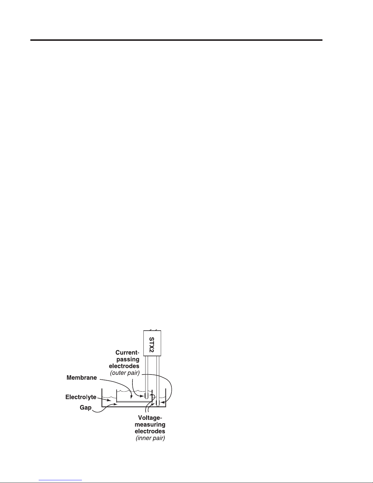
from 150W to less than 5W. (Endohm-6 is higher.) The shape of the current electrodes
allows a more uniform current density to ow across the membrane. See Fig. 14 and
Fig. 15, below. Fig. 14 demonstrates how the STX2 electrode measures TEER, and Fig.
15 shows how the Endohm chamber measures TEER. With xed electrode geometry,
the variation of readings on the same sample is 1-2W as compared to 5-10% of the
total reading using the STX2 electrodes. The Endohm, together with the EVOM2,
oers the most accurate, convenient and economical solution for trans membrane
electrical resistance measurement.
For automation of TEER measurements, consider the REMS AutoSampler that
integrates a robotic system and computer interface to automatically measure tissue
resistance in 24- and 96-well plates. The ability of the REMS AutoSampler to precisely
locate the electrode results in highly reproducible TEER measurement.
Fig. 14–(Left) The STX2 electrode measure TEER.
Fig. 15–(Right) The EndOhm electrode measure TEER.
Page 26

22 WORLD PRECISION INSTRUMENTS
DECLARATION OF CONFORMITY
Page 27

EVOM2
WORLD PRECISION INSTRUMENTS 23
WARRANTY
WPI (World Precision Instruments, Inc.) warrants to the original purchaser that this equipment, including its
components and parts, shall be free from defects in material and workmanship for a period of one year*
from the date of receipt. WPI’s obligation under this warranty shall be limited to repair or replacement, at
WPI’s option, of the equipment or defective components or parts upon receipt thereof f.o.b. WPI, Sarasota,
Florida U.S.A. Return of a repaired instrument shall be f.o.b. Sarasota.
The above warranty is contingent upon normal usage and does not cover products which have been modi-
ed without WPI’s approval or which have been subjected to unusual physical or electrical stress or on
which the original identication marks have been removed or altered. The above warranty will not apply if
adjustment, repair or parts replacement is required because of accident, neglect, misuse, failure of electric
power, air conditioning, humidity control, or causes other than normal and ordinary usage.
To the extent that any of its equipment is furnished by a manufacturer other than WPI, the foregoing
warranty shall be applicable only to the extent of the warranty furnished by such other manufacturer. This
warranty will not apply to appearance terms, such as knobs, handles, dials or the like.
WPI makes no warranty of any kind, express or implied or statutory, including without limitation any
warranties of merchantability and/or tness for a particular purpose. WPI shall not be liable for any damages, whether direct, indirect, special or consequential arising from a failure of this product to operate in
the manner desired by the user. WPI shall not be liable for any damage to data or property that may be
caused directly or indirectly by use of this product.
Claims and Returns
• Inspect all shipments upon receipt. Missing cartons or obvious damage to cartons should be noted on the
delivery receipt before signing. Concealed loss or damage should be reported at once to the carrier and
an inspection requested. All claims for shortage or damage must be made within 10 days after receipt of
shipment. Claims for lost shipments must be made within 30 days of invoice or other notication of shipment.
Please save damaged or pilfered cartons until claim settles. In some instances, photographic documentation
may be required. Some items are time sensitive; WPI assumes no extended warranty or any liability for use
beyond the date specied on the container.
• WPI cannot be held responsible for items damaged in shipment en route to us. Please enclose merchandise
in its original shipping container to avoid damage from handling. We recommend that you insure merchandise
when shipping. The customer is responsible for paying shipping expenses including adequate insurance on all
items returned.
• Do not return any goods to WPI without obtaining prior approval and instructions (RMA#) from our returns
department. Goods returned unauthorized or by collect freight may be refused. The RMA# must be clearly
displayed on the outside of the box, or the package will not be accepted. Please contact the RMA department
for a request form.
• Goods returned for repair must be reasonably clean and free of hazardous materials.
• A handling fee is charged for goods returned for exchange or credit. This fee may add up to 25% of the sale
price depending on the condition of the item. Goods ordered in error are also subject to the handling fee.
• Equipment which was built as a special order cannot be returned.
• Always refer to the RMA# when contacting WPI to obtain a status of your returned item.
• For any other issues regarding a claim or return, please contact the RMA department.
Warning: This equipment is not designed or intended for use on humans.
* Electrodes, batteries and other consumable parts are warranted for 30 days only from the date on which the
customer receives these items.
Page 28

USA
International Trade Center, 175 Sarasota Center Blvd., Sarasota FL 34240-9258
Tel: 941-371-1003 • Fax: 941-377-5428 • E-mail: sales@wpiinc.com
UK
1 Hunting Gate, Hitchin, Hertfordshire SG4 0TJ
Tel: 44 (0)1462 424700 • Fax: 44 (0)1462 424701 • E-mail: wpiuk@wpi-europe.com
Germany
Saarstraße 23, D-61169 Friedberg (Hesson), Germany
Tel: +49 (0)6031 1602171 • Fax: +49 (0)6031 1602180 • E-mail: wpide@wpi-europe.com
China & Hong Kong
WPI Shanghai Trading Co., Ltd.
Rm 25e, No8 Dongfang Rd., Pudong District, Shanghai, 200120 PR China
Tel: +86 21 6888 5517 • E-mail:chinasales@china.wpiinc.com
Brazil
Av. Conselheiro Nébias, 756 sala 2611, Santos-CEP: 11045-002, São Paulo Brazil Tel: (013) 406-
29703 • E-mail: info@brazil.wpiinc.com
Internet
www.wpiinc.com • www.wpi-europe.com • www.wpiinc.cn • www.wpibrasil.com.br
 Loading...