

World Marketing of America DFA-45 User Manual
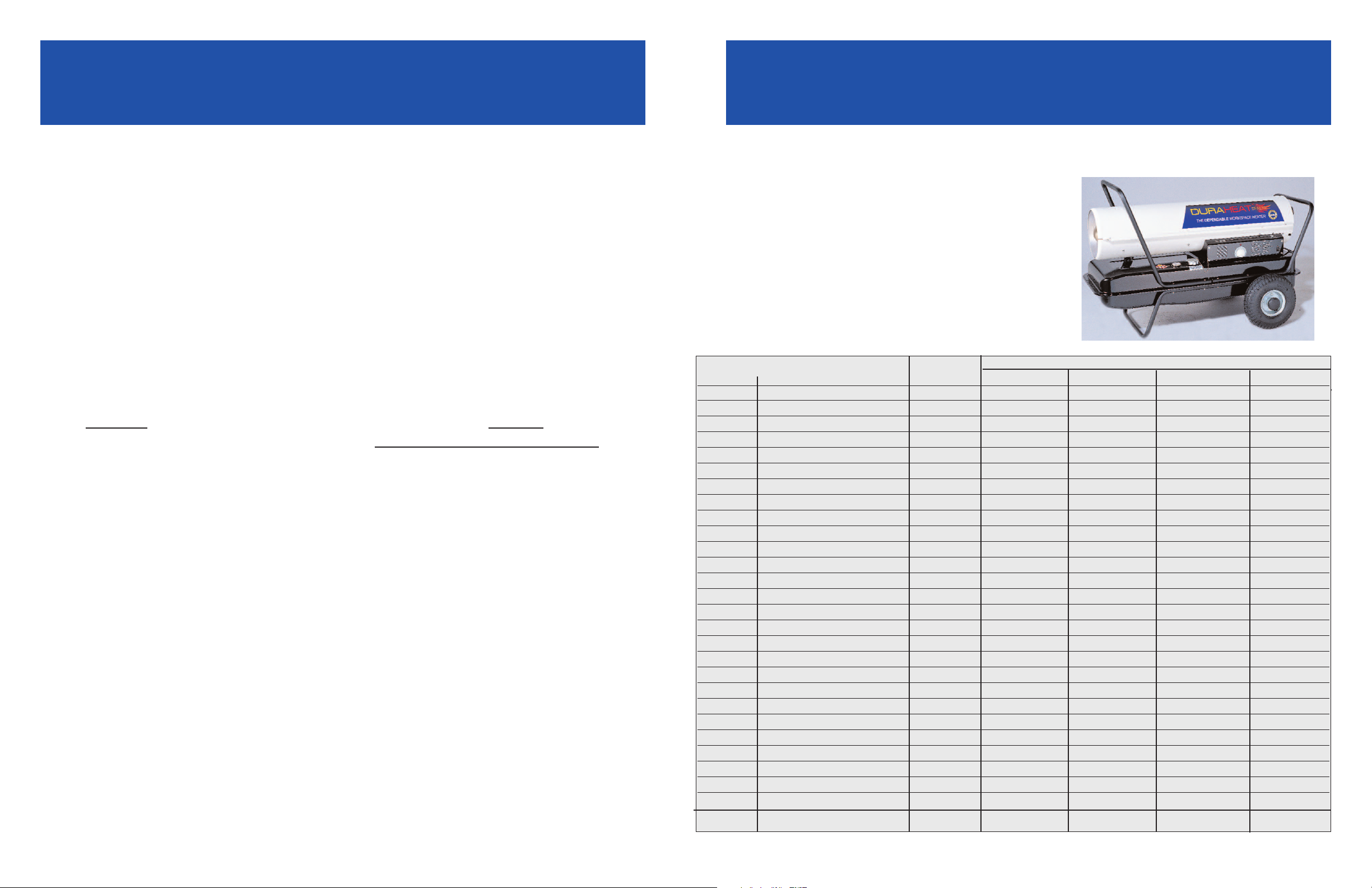
DuraHeat®Forced Air Heater
DuraHeat
®
Forced Air
Troubleshooting Guide
Air Pressure Problems
Always use an air pressure gauge to check or set air pressures.
DFA-45 2.8 PSI DFA-170T,170C 6.5 PSI
DFA-65 3.5 PSI DFA-210T,210C 8.5 PSI
DFA-120,120T 4.5 PSI
If the pressure is TOO LOW turn the adjustment screw clockwise. This will increase the flame.
If the pressure is
Note: If the heater burns OK with the Upper Shell off, but turns off when the cover is installed, the
pressure is too low.
If you can't achieve the proper pressure setting - try pulling the air line off the pump body and block
air line fitting tight
This should peg pressure gauge. If it does not, the problem is inside the pump body.
ger.
Check for: Cracked plastic cover
Sometimes it's hard to see the air leak. A solution of 50/50 soap and water can be applied to the
pump to find the leak.
CAUTION! BE CAREFUL NOT TO APPLY THIS SOLUTION TO ANY ELECTRICAL PARTS AS
IT WILL DAMAGE THE COMPONENTS AND CREATE A SHOCK HAZARD.
If pressure gauge does peg - try removing the air line from the nozzle end and replace it at pump
body end. Then plug air line and adjustment screw end. If it
problem lies with the Air Line. The air line may be cracked, cut, torn, split, rotted, etc.
Air Line to correct the problem.
OWNER’S MANUAL NOTE:
operating or attempting to service or repair any appliance. Failure to follow all instructions provided
in the owner’s manual may result in property damage, personal injury, or death.
7/07 Pt. No. FAPARTS
TOO HIGH turn the adjustment screw counter-clockwise to reduce the flame.
with finger then remove adjustment screw and plug the hole tight
Cracked pump body
Cracked rotor
Loose pump body screws
Rubber seal on filter seated properly
does not peg the gauge, then the
(WARNING) Always review the owner’s manual completely before
with another fin-
Replace the
Parts & Service Guide
FFOORR TTEECCHHNNIICCAALL
AASSSSIISSTTAANNCCEE CCOONNTTAACCTT UUSS AATT::
Tech Assistance: 814-643-2299
Ordering: 800-233-3202
Fax: 800-421-1357
Email:
iinngg..ccoom
m
tteecchhssvvcc@@wwoorrllddmmkktt-
or visit our website at:
KEY NO. DESCRIPTION DFA45 DFA65/65T DFA120/120T DFA170T/170C DFA210T/210C
1 Fuel Tank Assembly “Pre 04” 21-1001 21-1001 21-1002 21-1003 21-1003
1 Fuel Tank Assembly 04-05 21-1401 21-1401 21-1402 21-1403 21-1403
1.1 Drain Plug N/A N/A 21-4401 21-4401 21-4401
2 Fuel Gauge 21-1004 21-1004 21-1005 21-1005 21-1005
3 Fuel Filter Assembly 21-1006 21-1006 21-1007 21-1007 21-1007
4 Fuel Cap 21-1008 21-1008 21-1008 21-1008 21-1008
5 Power Cord 21-1009 21-1009 21-1009 21-1009 21-2101
6 Power Switch 21-1010 21-1010 21-1010 21-1010 21-1010
7 Display P.C.B. Assembly 21-1011 21-1011 21-1011 21-1012 21-1012
8 Thermostat Control Knob ----- ----- 21-1013 21-1013 21-1013
9 Lower Shell Reference Reference Reference Reference Reference
10 Air Line 21-1017 21-1017 21-1018 21-1069 21-2108
11 Temperature Limit Control 21-1019 21-1019 21-1020 21-1020 21-2109
12 Combustion Chamber 03 21-1021 21-1021 21-1022 21-1023 21-2110
13 Photocell Holder Reference Reference Reference Reference Reference
14
15 Photocell FA1007 FA1007 FA1007 FA1007 FA1023BK
16
16-1 Nozzle Kit FA1001 FA1002 FA1003 FA1004 FA1011BK
16-2 Nozzle Seal Washer 21-1027 21-1027 21-1027 21-1027 21-1027
16-3 Nozzle Seal Spring 21-1028 21-1028 21-1028 21-1028 21-1028
16-4 Burner Head 21-1029 21-1029 21-1030 21-1031 21-1031
16-5 Spark Plug FA1008 FA1008 FA1009 FA1009 FA1021BK
17 Motor and Pump Assembly Reference Reference Reference Reference Reference
17-1
17-2 Pump Body 21-1038 21-1038 21-1038 21-1038 21-2120
17-3
Fuel Line
Burner Head
Motor
Rotor Kit FA1000 FA1000 FA1000 FA1000 FA1022BK
Rotor Only 21-2125
Assembly
PLEASE READ OWNER’S MANUAL BEFORE PERFORMING
21-1024
Reference Reference Reference Reference Reference
21-1035
ANY MAINTENANCE OR SERVICE
21-1024 21-1025 21-1025 21-2111
21-1035
-
PART NO.
21-1036
21-1037 21-2119

DuraHeat®Forced Air Heater
DuraHeat®Forced Air
Parts List (Cont’d)
PART NO.
KEY NO. DESCRIPTION
17-4 Rotor Blade 21-1039 21-1039 21-1039 21-1039 21-2122BK
17-5 End Pump Cover 21-1040 21-1040 21-1040 21-1040 21-1040
17-6 Filter Kit FA1005 FA1005 FA1005 FA1005 FA1005
17-7 Lint Filter 21-1090 21-1090 21-1090 21-1090 21-1090
17-8 Output Filter 21-1091 21-1091 21-1091 21-1091 21-1091
17-9 End Filter Cover 21-1041 21-1041 21-1041 21-1041 21-1041
17-10 Plug/Pump Adj. Kit FA1006 FA1006 FA1006 FA1006 FA1006
17-11 Ball See 17-10 See 17-10 See 17-10 See 17-10 See 17-10
17-12 Spring See 17-10 See 17-10 See 17-10 See 17-10 See 17-10
17-13 Adj. Screw See 17-10 See 17-10 See 17-10 See 17-10 See 17-10
18 Fan Assembly 21-1042 21-1042 21-1043 21-1044 21-1044
19 Ignitor 21-1045 21-1045 21-1046 21-1047 21-2124
20 Side Cover Right No T-Stat 21-1070 21-1048 21-1049 ------- -------20 Side Cover Right T-Stat Mdl ----- 21-6502 21-1202 21-1702 (c) 21-2102(c)
21 Side Cover Left No T-Stat 21-1051 21-1051 21-1052 ------- -------21 Side Cover Left T-Stat Mdl ----- 21-6504 21-6505 21-1704 (c) 21-1704(c)
22 Fan Guard 21-1054 21-1054 21-1055 21-1055 21-2129
23 Main P.C.B. 2001 Models 21-1056 21-1056 21-1057 21-1058 21-2150
23 Main P.C.B. 2002-3 Models 21-2151 21-2151 21-2152 21-2150 21-2150
23 Main P.C.B. 2004 Models 21-2151 21-2153 (t) 21-2153 (t) 21-2153 (c) 21-2153 (c)
23-1 Fuse FA1015 FA1015 FA1016 FA1017 FA2100
24 Clip Nut 21-1059 21-1059 21-1059 21-1059 21-1059
25 Upper Shell Reference Reference Reference Reference Reference
26
27 Wheel Standard Only ----- ----- 21-1066 21-1066 21-1066
27 Wheel Pneumatic C-Models ----- ----- ----- 21-5600 21-5600
Not Pressure Gauge ----- ----- ----- 21-1207 21-1207
Shown (Built-In) “C” Models
Not Shown Back Handle ------ ------ ------- 21-1080 (170C) 21-1080(210C)
Handle (Front)
Hardware Kit 21-9601 21-9601 21-9602 21-9602 21-9603
Cord Wrap C-Models ----- ----- ----- 21-9500 21-9500
ADDITIONAL ACCESSORIES:
Air Pressure Gauge HA1180 (all models)
Thermostat HA1210 (all models)
FFOORR TTEECCHHNNIICCAALL AASSSSIISSTTAANNCCEE CCOONNTTAACCTT UUSS AATT::
Tech Assistance: 814-643-2299 • Ordering: 800-233-3202 • Fax: 800-421-1357
techsvc@worldmkting.com • or visit our website at worldmkting.com
DFA45 DFA65/65T DFA120/120T DFA170T/170C DFA210T/210C
21-1063 21-1063 21-1064 21-1065 21-1065
Troubleshooting Guide
Heater ignites but MAIN PCB 1. Wrong pump pressure 1. Make Pump Pressure Adjustment
assembly shuts heater off after
a short period of time. 2. Dirty Air Output, Air Intake 2. Replace Air Output, Air intake
Lamp is flickering)
(
Heater will not ignite but 1. No fuel in tank 1. Fill tank with kerosene
motor runs for a short period 2. Wrong pump pressure 2. Make Pump Pressure Adjustment.
of time. (Lamp is flickering)
Fan doesn’t turn or turns slowly 1. Thermostat setting is too 1. Turn thermostat control knob
when heater is plugged in and low (DFA170T
power switch was in the “ON” 2. Bad electrical connection
position (Lamp is on or flickering) between motor and MAIN
Heater ignites but shuts off 1. Ambient temperature is 1. Heater cannot be operated in
quickly (Lamp is on) too high temperatures above 85F/24C
OR 2. Defective T-Stat 2. Replace T-Stat
Heater will not turn-on position
(Lamp is off) 4. No electrical power 4. Check to insure heater cord and
nd Lint Filter and Lint Filters
a
3. Dirty Fuel Filter 3. Replace Fuel Filter
. Dirt in Nozzle 4. Replace Nozzle
4
5. Dirty Photocell Lens 5. Clean Photocell Lens
6. Photocell Assembly not 6. Make sure photocell boot is
properly installed. (Not properly seated in bracket
seeing the flame)
7. Bad electrical connection 7. Check electrical components
between photocell and MAIN
PCB assembly
8. Defective photocell 8. Replace photocell
9. Defective P.C.B. Board 9. Replace P.C.B. Board
3. Carbon deposits on spark 3. Clean or replace Spark Plug,
plug and/or improper gap or adjust gap.
4. Dirty fuel filter 4. Replace Fuel Filter.
5. Dirt in nozzle 5. Clean or Replace Nozzle.
6. Water in fuel tank 6. Flush fuel tank with clean
kerosene.
7. Bad electrical connection 7. Check electrical connections.
between ignitor and MAIN
PCB assembly
8. Ignitor wire is not attached to 8. Attach ignitor wire to spark
spark plug plug.
9. Defective ignitor 9. Replace ignitor.
10. Cracked spark plug 10. Replace spark plug
model) to a higher setting
2. Check electrical connections
PCB assembly
3. Defective Motor 3. Replace Motor
3. Temperature limit safety 3. Turn power switch to “OFF”
device is overheated and allow to cool
( wait about 10 min.).
Then turn power switch to “ON”
extension cord are plugged in.
Check power supply
5. Blown fuse 5. Replace fuse in PCB
board
6. Bad electrical connection between 6, Check electrical connections
temperature limit safety device
and PCB board
7. Defective P.C.B. Board 7. Replace P.C.B. Board.
Refer to the Owner’s Manual for complete information
 Loading...