

Worldlawn WY36FS481VH, WY48FS481VH Operator's Manual

WY36FS481VH
WY48FS481VH
OPERATORS
MANUAL

WARNING:
DO NOT allow children to operate the
machine. DO NOT allow any adult to operate
the machine without proper instruction.
CAUTION:
Never add fuel to the tank while the engine is
running or hot.
ALWAYS WAIT at least five
minutes before refueling and REFUEL WITH THE
ENGINE OFF. KEEP FUEL AWAY FROM
SPARKS OR FLAMES. WIPE AWAY any fuel
spillage BEFORE starting unit. Never fill the fuel
tank indoors. Wipe up any spilled gasoline.
Gasoline is highly flammable - NO SMOKING.
Your mower is only as safe as the operator! Operator carelessness or error may result
in serious bodily injury. Improper maintenance of the machine may also result in injury.
Please read and follow these instructions on Safe Operation and be certain that anyone
using this mower fully understands and follows these instructions.
1. Familiarize yourself with the controls
and know how to stop this mower.
2. Inspect your work area carefully.
Remove debris from the area to be cut.
Keep all bystanders away from the
mowing area.
3. Avoid contact with moving parts. Keep
hands and feet clear of the mower deck
and all moving parts.
4. Never direct the discharge of material
toward bystanders nor allow anyone
near the machine while in operation.
5. Never tamper with safety devices or
guards. If a guard or safety device is
damaged or removed, replace it before
operating the mower.
6. Handle gasoline carefully: use an
approved gasoline container; fill the fuel
tank to bottom of drop tube with good
quality unleaded gasoline. Operator
must wear proper shoes and clothing,
which may also include safety glasses
and ear protection.
7. Mow only during daylight hours or under
very good artificial light.
8. Do NOT mow in slippery conditions ,
keep a firm grip on the handle bars,
NEVER RUN.
9. The safety shield over the grass
discharge must always be bolted in
place and in the down position unless
the grass catcher back plate is
completely installed.
10. Do NOT leave the operator position
unless the engine has been killed and
blades have stopped.
11. If a solid object has been hit by the
blades, stop the machine and check for
damage. Repair or replace damaged/
broken part(s) prior to restarting the
engine.
12. Do NOT allow anyone to stand or walk
on the grass discharge side of the
mower when the mower is in operation.
13. Do NOT mow close to drop-offs, deep
ditches or other hazards. Mow hillsides
very carefully by mowing across the face
of slopes, not up or down. Do NOT
mow on steep slopes.
14. To avoid burns, DO NOT TOUCH the
engine or muffler immediately after
operation.
1
SPECIFICATIONS
Belt Tension Guide
Belt
Engine to Deck
Right Blade Drive
Engine to Pump
Inch Deflection
1/2”
1/2”
(48”,52”, And 60” only)
1/2”
Hydraulic System
Capacity
(to the top of the tank baffle)
Filter
Oil
A Hi
Worldlawn P/N 423361
gh quality 15W50 synthetic engine oil
Assembly Instructions
1. Remove inner parts box and handle from
crate. Remove outside frame work so
that the mower is setting on the pallet.
2. On a 36" mower, use 3 – 5/16" X 1 3/4"
bolts and 3 – 5/16" whizlocks and bolt the
bumper into place. (On the 48" there are
4 - bumper bolts required.) The
whizlocks should go to the inside of the
deck. When assembling a 48" mower,
make sure that the bumper is flush with
the deck on both ends of the bumper.
3. Using 6 – 3/8" X 1" bolts (3 – used for
each caster) and 6 – 3/8" whizlock nuts,
bolt the casters into place. Position
whizlock nuts to the inside of the deck.
4. Using 2 – 1/4" X 3/4" bolts and 2 – 1/4"
nyloc nuts secure the speed control lever
assembly to the underside of the mount
plate on the lower handle. Connect the
speed control link to the control cam arm
and secure with 1 - 1/4" nyloc nut.
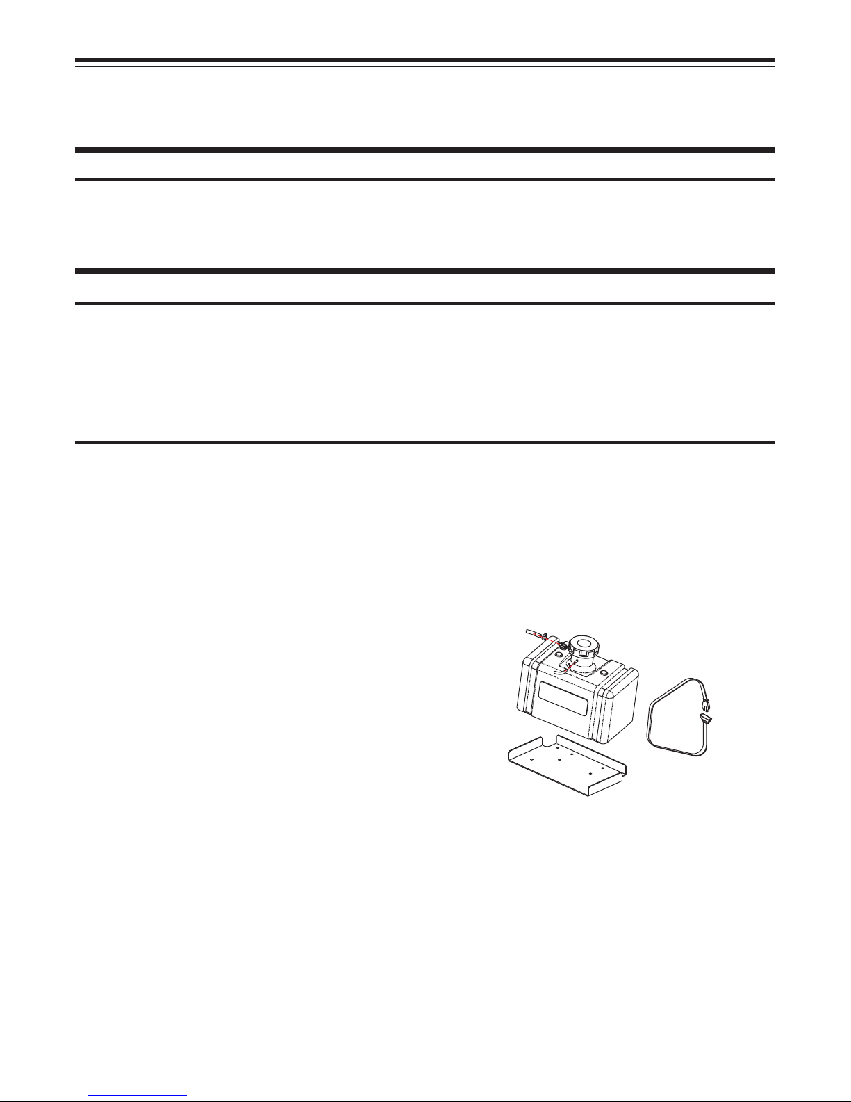
5. Mount the gas tank using the 2 – nylon
hold down straps, pulling tension on the
buckles until secure. Attach fuel line on
tank to fuel filter on engine. Attach vapor
recovery line on engine to vent barb on
fill neck. Secure all connections with
hose clamps.
6. Using the remaining 3/8" X 1" bolts and
the 4 – 3/8" nyloc nuts, bolt the upper
handle into position. (Remember that
there are 3 – height settings for the
How to Adjust
Turnbuckle at Idler
Threaded Rod
Fixed idler with Slot
3 quarts
Fig. 1
2

Assembly Instructions
handle for operator comfort.) Route the
wiring harness along the handle, plugging it
into the blade control switch, o.p.c. and
speed control switch located under the
speed control plate. There is not a specific
color code for hooking up the harness. Run
the throttle cable around the left hand side
of the engine to the throttle plate, Place the
throttle in the full speed detent, with the
throttle wire hooked in the speed control
arm on the engine throttle plate, pull on the
conduit until the speed control arm is at
maximum speed, tighten conduit clamp.
7. At this point, you are ready to oil and fuel
the engine. With that being done, take
the unit and raise the rear wheels off the
ground so that they may free wheel.
Block the unit up securely so that you
may run the engine with no danger of it
falling from the stand. With the speed
control in the neutral position, start the
engine and run it at 3/4 to full throttle.
Using a 5/16" wrench adjust the speed
control link, to set the right hand wheel to
neutral no matter what the left hand
wheel does. With that accomplished,
lock the lock nuts into place on speed
control link. If the left hand wheel is not
neutralized use a 1/2" wrench, to break
the lock nut loose on the pump link and
adjust the rod end to neutral the left hand
wheel. After accomplishing neutral, shut
the engine off and remove the support
blocks from under the machine. With the
engine shut down, take the drive rods
and bolt them onto the main control shaft
using the 5/16" nyloc nuts provided.
Adjust the length of the rod so that the
pins in the drive levers are just a little
under center of the neutral lock on the
thumb lock. (See fig.)
8. You are ready for your test run to set the
full speed tracking. Remember to check
the air pressure in the tires. Rear wheels
Hydro Drive Thumblock
should be set at 12 psi, front casters to
20 psi. Run unit at full throttle and set
control lever to the full speed setting.
The test run should be made on some
type of hard surface with the ground
being fairly level. If the machine pulls
one way in full speed, adjust the slow
side stop bolt up to speed up the slow
motor. If there is not enough adjustment
to speed up the slow motor, you may
have to lengthen the stop bolt on the fast
side. Run that machine at an
intermediate speed. If you have a
tracking problem after full speed tracking
is set, the adjustment is in the pump arm
rod end. This is remedied by adjusting
the length of the pump arm. Brake the
lock nut loose on the pump arm and
remove the bolt from the rod end that
attaches it to the link. To increase the
pump speed, shorten the pump arm. To
decrease the speed, lengthen the pump
arm. Usually about two full turns on the
pump arm rod end to speed up or slow
down is adequate. (See fig.3)
Neutral Lock
Drive-Rod
Fig. 2
3
 Loading...