

WORLD-CCTV 722RIII-IP User Manual
Page 1 of 95
Contents
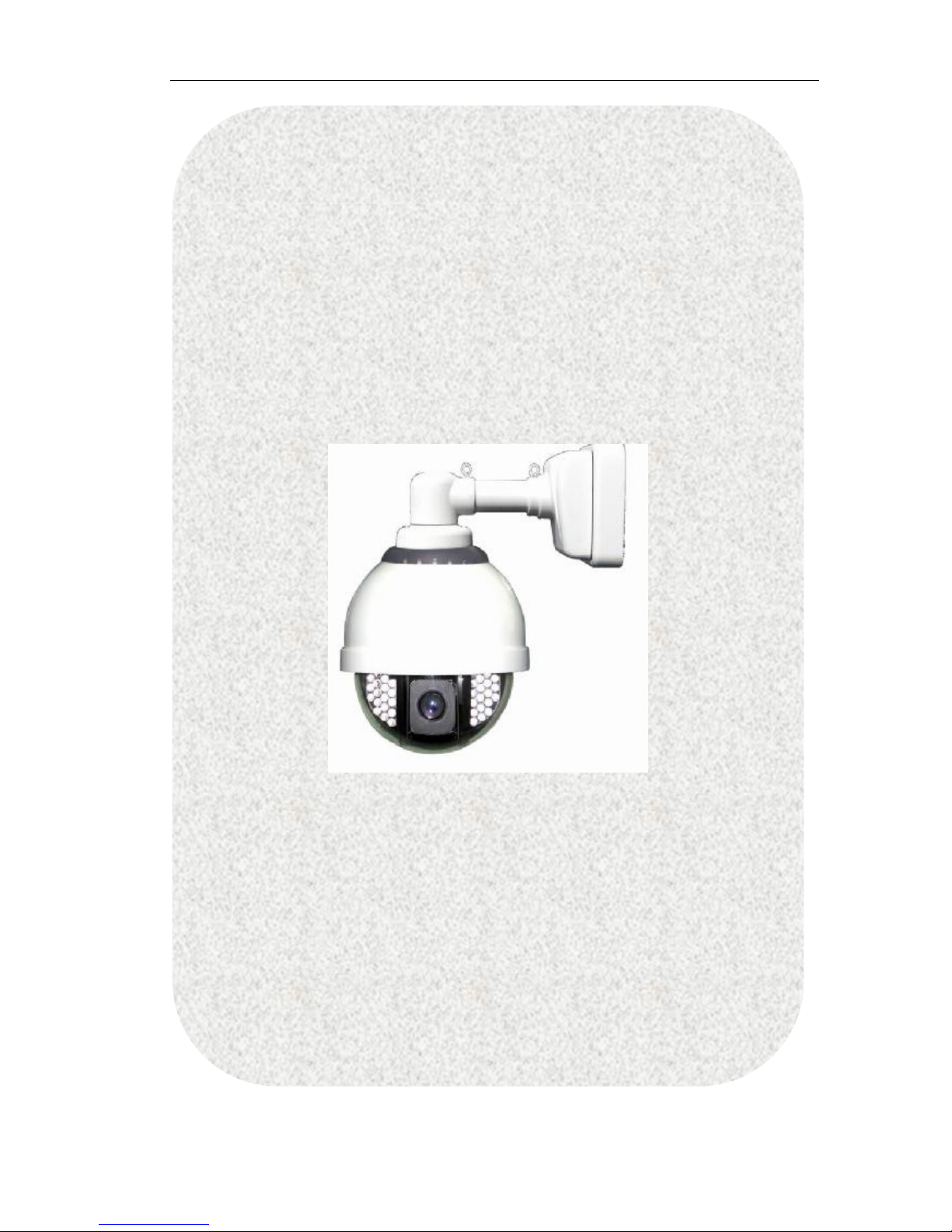
722RIII-IP
Outdoor Infrared
H.264 IP Speed Dome
User Manual
722RIII-IP: 22X optical zoom IP Speed Dome, D1;

Page 2 of 95
Copyright Declaration..............................................................................................................5
Software License Agreement...................................................................................................5
1 Before you this product..........................................................................................................6
2 Package Content...................................................................................................................7
3 Physical characteristic...........................................................................................................7
4 Installation................................................................................................................................8
4.1 Hardware Installation...................................................................................................8
4.1.1 Wall Mount..........................................................................................................8
4.1.2 Pendant Mount..................................................................................................9
4.1.3 DIP Setup:..........................................................................................................11
4.1.4 connect the Ethernet......................................................................................13
4.1.5 connect the power..........................................................................................13
4.1.6 connect the external device.........................................................................13
4.2 Software Installation...................................................................................................14
4.2.1 Using Web Browsers.........................................................................................14
4.2.2 CMS Installation................................................................................................16
4.3 IP Surveillance System Connection..........................................................................21
5 IP camera configuration......................................................................................................22
5.1 video and audio settings (General, OSD display, Audio Setting)........................22
5.1.1 Video setting.....................................................................................................22
Advanced image setting skill..................................................................................24
5.1.2 Image setting....................................................................................................25
5.1.3 Video Flip and Mirror........................................................................................26
5.1.4 Audio setting.....................................................................................................26
5.2 OSD/MASK setting......................................................................................................27
5.3 network settings (General, PPPoE,DDNS, FTP, E-mail, Wifi, 3G).............................28
5.3.1 General setting.................................................................................................28
5.3.2 PPPOE................................................................................................................28
5.3.3 DDNS..................................................................................................................29
5.3.4 E-Mail Setting....................................................................................................30
5.3.5 FTP setting..........................................................................................................30
5.3.5 WIFI setting (Only for WIFI IP Camera models).............................................31
5.3.6 3G setting (Only for 3G IP Camera models).................................................33
5.4 PTZ setting....................................................................................................................36
5.5 System (version, time configuration, system update, user)..................................37
5.5.1 system update, restore, reboot......................................................................37
5.5.2 Time configuration...........................................................................................39
5.5.3 Device information..........................................................................................39
5.5.4 user management...........................................................................................40
5.6 Alarm (sensor alarm, motion detection).................................................................41
5.6.1 sensor alarm......................................................................................................41
5.6.2 motion detection.............................................................................................43
5.7 SD Card Record..........................................................................................................45
5.7.1 Format SD card................................................................................................45

Page 3 of 95
5.7.2 Schedule record on SD card..........................................................................45
5.7.3 Schedule snapshot on SD card......................................................................46
5.7.4 Overwrite setting..............................................................................................47
5.7.4 Play the record file of SD card.......................................................................48
5.7.5 Download the record files or snapshots of SD card....................................49
5.8 Manual Record over IE..............................................................................................50
5.8.1 Local record file path......................................................................................50
5.8.2 Play Local record file.......................................................................................50
6 How to use Management software?.................................................................................52
6.1 System login and logout............................................................................................52
6.1.1 System Login.....................................................................................................52
6.1.2 Log out system..................................................................................................52
6.1.3 Minimize system................................................................................................52
6.2 System setting.............................................................................................................53
6.2.1 Server management (Add IP camera).........................................................53
6.2.2 User management...........................................................................................56
6.3 IP Camera live view...................................................................................................58
6.3.1 Log in and log off IP camera..........................................................................58
6.3.2 Live view IP camera.........................................................................................58
6.3.3 Auto log in IP canera and Auto Connect IP camera.................................59
6.4 Remote setup IP Camera..........................................................................................60
6.5 Multi-view IP camera and control............................................................................60
6.5.1 Loop swtich.......................................................................................................60
6.5.2 Sound play control and two way audio.......................................................62
6.5.3 PTZ control.........................................................................................................63
6.6 Snapshot......................................................................................................................64
6.6.1 How to Snapshot..............................................................................................64
6.6.2 Search snapshot...............................................................................................64
6.7 Record.........................................................................................................................65
6.7.1 General setting (Record path, overwrite, record package).....................65
6.7.2 Time Schedule record over Management Software..................................66
6.7.3 Manual record..................................................................................................67
6.7.4 Alarm record.....................................................................................................68
6.8 Playback......................................................................................................................69
6.9 Alarm management..................................................................................................71
6.9.1 Sound Alarm.....................................................................................................71
6.9.2 Pop up alarm message...................................................................................72
6.9.3 Pop up camera video.....................................................................................73
6.9.4 Electronic Map alarm......................................................................................74
6.9.5 Email notification...........................................................................................78
6.9.6 History event.....................................................................................................81
6.10 Toolbar.......................................................................................................................83
6.10.1 Bottom Toolbar...............................................................................................83
6.10.2 PTZ Control Toolbar........................................................................................85

Page 4 of 95
6.10.3 Alarm Control Toolbar...................................................................................85
7 Appendix...............................................................................................................................85
7.1 FAQ...............................................................................................................................85
7.2 factors influencing system capability......................................................................87
8 Speed Dome Operation......................................................................................................87

Page 5 of 95
Copyright Declaration
This manual is provided by WORLD-CCTV Technology Co., Ltd as the support file for the
Network Video Server, IP camera, etc. Both the software and this manual are
copyrighted and protected by the laws of the People's Republic of China.
All rights reserved; no part of this manual may be extracted, modified, copied,
reproduced or transmitted in any form or by any means, electronic or mechanical,
without prior written permission from WORLD-CCTV. By using this manual, you agree to
the following Software License Agreement.
WORLD-CCTV reserves the right to revise this manual without prior note. Please contact
WORLD-CCTV for the latest version of this manual.
WORLD-CCTV has made every effort to ensure the accuracy of this manual but does
not guarantee the absence of errors. Moreover, WORLD-CCTV assumes no
responsibility in obtaining permission and authorization of any third party patent,
copyright or product involved in relation to the use of this manual.
Note: Windows, Windows NT, Windows 2000, Windows XP and etc. mentioned in this
book are registered trademarks of Microsoft Corporation.
WORLD-CCTV Software License Agreement
1. WORLD-CCTV Technology Co., Ltd (hereinafter referred to as ‘WORLD-CCTV’) owns
the copyright of ‘this software and its accessories, relative files and archives’
(hereinafter referred to as ‘this product’). No organization, enterprise, agency or
individual may use this product without our authorization.
2. We authorize those who achieve the following two requirements to use this product
for free:
A. Using this product with hardware products purchased from WORLD-CCTV
through a legitimate marketing channel;
B. Promising not to transmit the whole or part of this product to any third party
without prior permission from WORLD-CCTV.
3. Any organization, enterprise, agency or individual, except as otherwise subject to
the second article of this license agreement, must obtain the written permission
from WORLD-CCTV before using this product.
4. The authorized organizations, enterprises or individuals have no right to transfer the
authorization.
5. The use of this product indicates that you have fully understood and accepted all
terms in this license.

Page 6 of 95
1 Before you this product
Safety Notes
All the safety and operation instructions should be read before the unit is used.
Location
Ensure the unit is ventilated to protect from overheating.
Ensure there is a 3cm gap between on both side of the unit
This unit is stored in low humidity and dust free area. Avoid places like damp basements
or dusty hallways
Ensure the unit is not located where it’s likely to be subject to mechanical shock
Servicing
Do not attempt to service this unit yourself as opening or removing the covers may
expose you to dangerous voltage or other hazards
Ventilation
Ensure the unit is ventilated to protect from overheating as detailed above.
Warning: To prevent fire or shock hazard, do not expose this unit to rain or moisture. The
lighting flash with arrowhead symbol within an equilateral triangle is indented to alert
the user of this unit there are dangerous voltages within the enclosure that may be of
sufficient magnitude to constitute a risk of electric shock.
Lightning Strike
The unit has some in-built protection for lightning strike, however it is recommended
that isolation transformers be fitted to the system in areas where lightening is a common
occurrence.
Page 7 of 95
2 Package Content
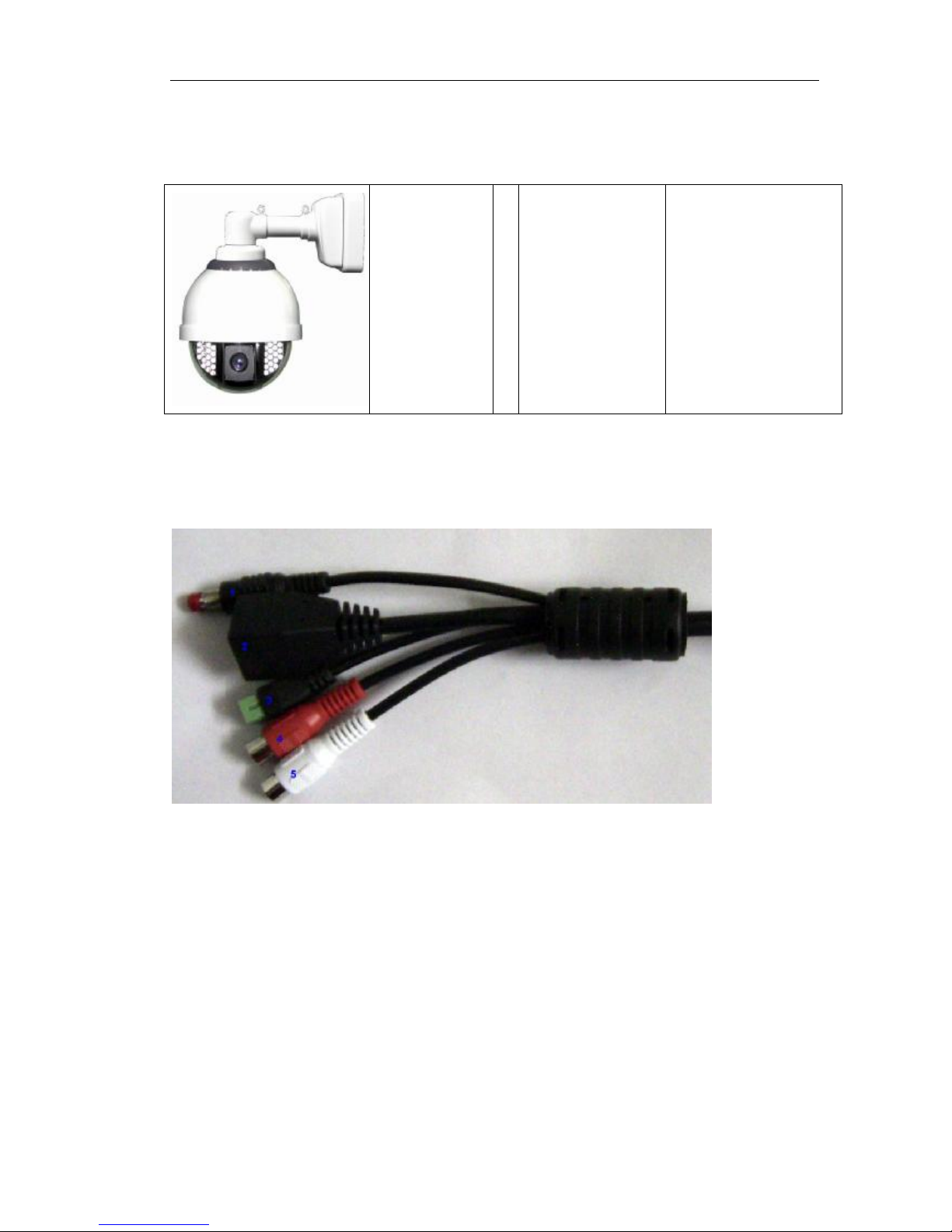
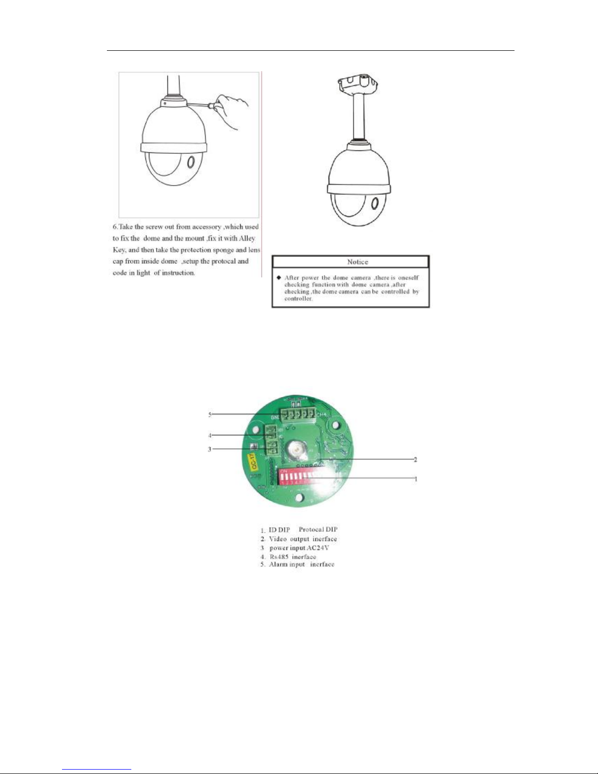
3 Physical characteristic
1 Reset
Under power on status, press the reset buttons for continous 10-15 seconds to restore
the factory settings including the network settings.
2 Ethernet: The IP camera connects to the LAN or WAN by a standard RJ45 connector.
IP camera can auto detect the speed of local network segment (10Base-T/100Base-TX
Ethernet)
3 Power: AC 24V input.
4 Red connector: audio out, connect the speaker
5 White connector: audio line in, connect the sound amplifier.
Infrared IP
speed Dome
Accessory ü Power Adaptor
ü Software CD
ü Wall Bracket
Page 8 of 95
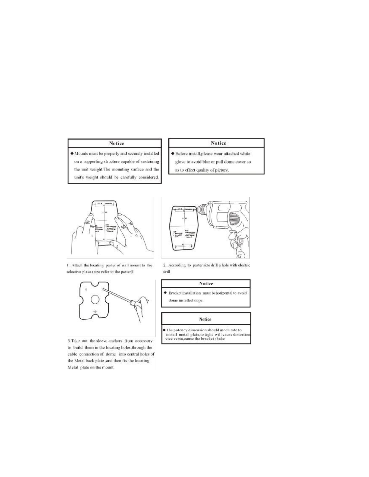
4 Installation
4.1 Hardware Installation
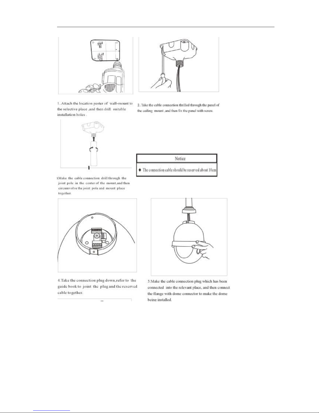
4.1.1 Wall Mount
Due to there has the ceiling place, you may use ceiling mount installation.
The following introduction is ceiling mount installation:
Page 9 of 95
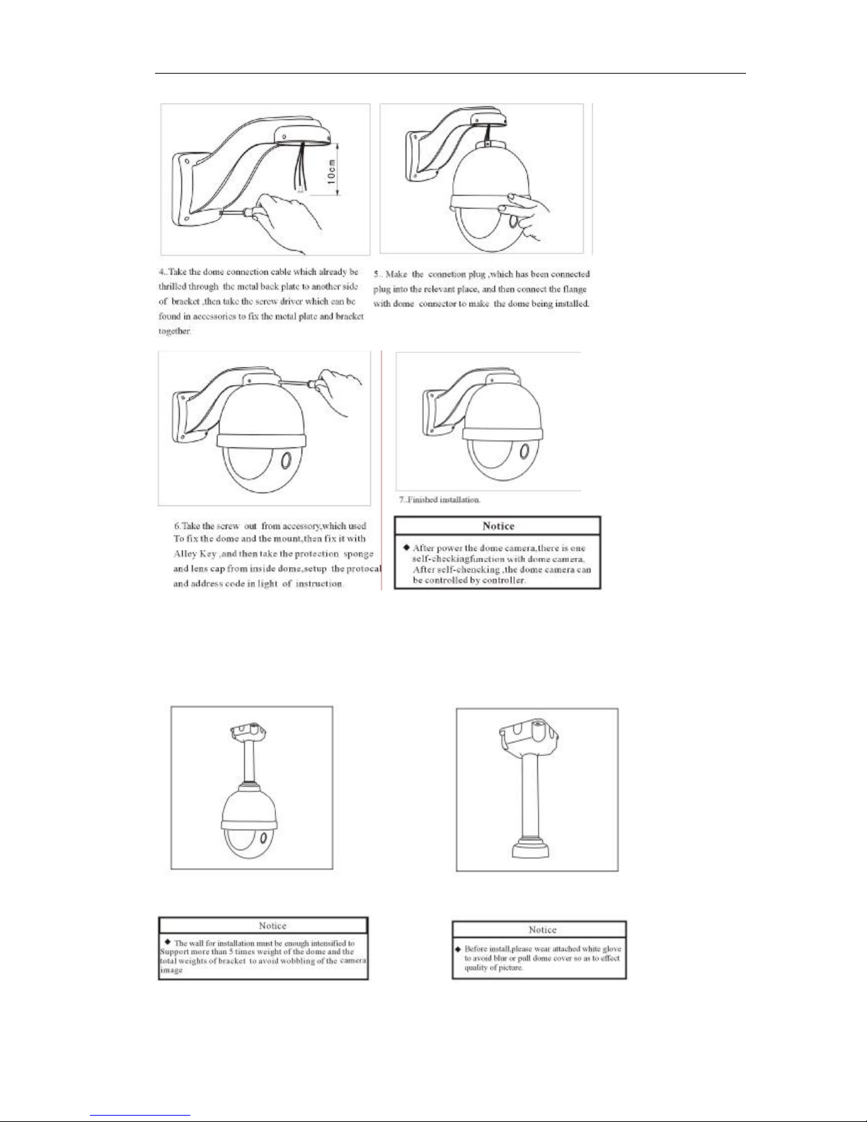
4.1.2 Pendant Mount
Indoor Speed Dome Pendent Bracket Dimension
Page 10 of 95
Page 11 of 95
7. Finished Installation
4.1.3 DIP Setup:
Page 12 of 95
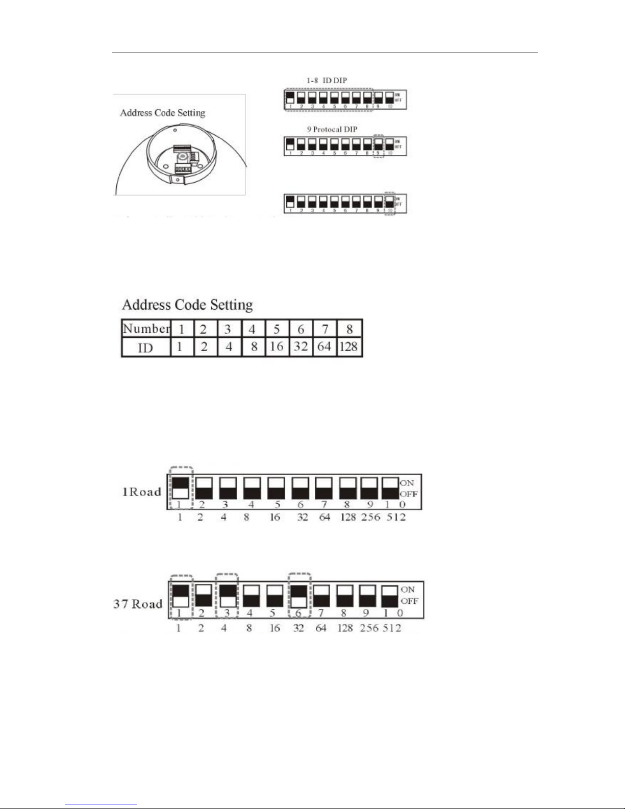
Before use Intelligent High Speed Pan must setting ID Dip, ID eight dials the code switch establishment
by the PCB board on, used binary system 8421code.1024 is max encode, ON state of switch
means‘1’and OFF means the switch ON condition 1 expressed OFF, the establishment method sees
explanation
DIP switch has defined address number as above shows:No1 means the first cable address
number, No2 means the second cable address number, No3 means the forth cable
address number, No4 means the eighth cable address number....needs to establish several
groups will make address number which corresponds to number dial “ON” the position .If
must dial in the address number which in the table has not appeared existing address
number will adding together available number in the table to obtain.
For example: if dial the first group, make address number 1 correspond No 1 turn “ON”
position.
For example: If want dial 37 group, put address number1、4、32 add to 37, make correspond
number(1、3、6) turn “ON” position. Others have an analogy.

Page 13 of 95
4.1.4 connect the Ethernet
Depending on the user’s application, an Ethernet cable is necessary. The Ethernet
cable should meet the specs of UTP Category 5 and not exceed 100 meters in length.
Make sure the Ethernet is firmly connected to a switch hub. The network status LED is
steady orange.
4.1.5 connect the power
Plug in the power adapter (24V AC 3A).
4.1.6 connect the external device
4.1.6.1 Connect Audio
Aout(Red Connector): Connect sound amplifier
A-inInterface(white connector): connect speaker in A-out interface
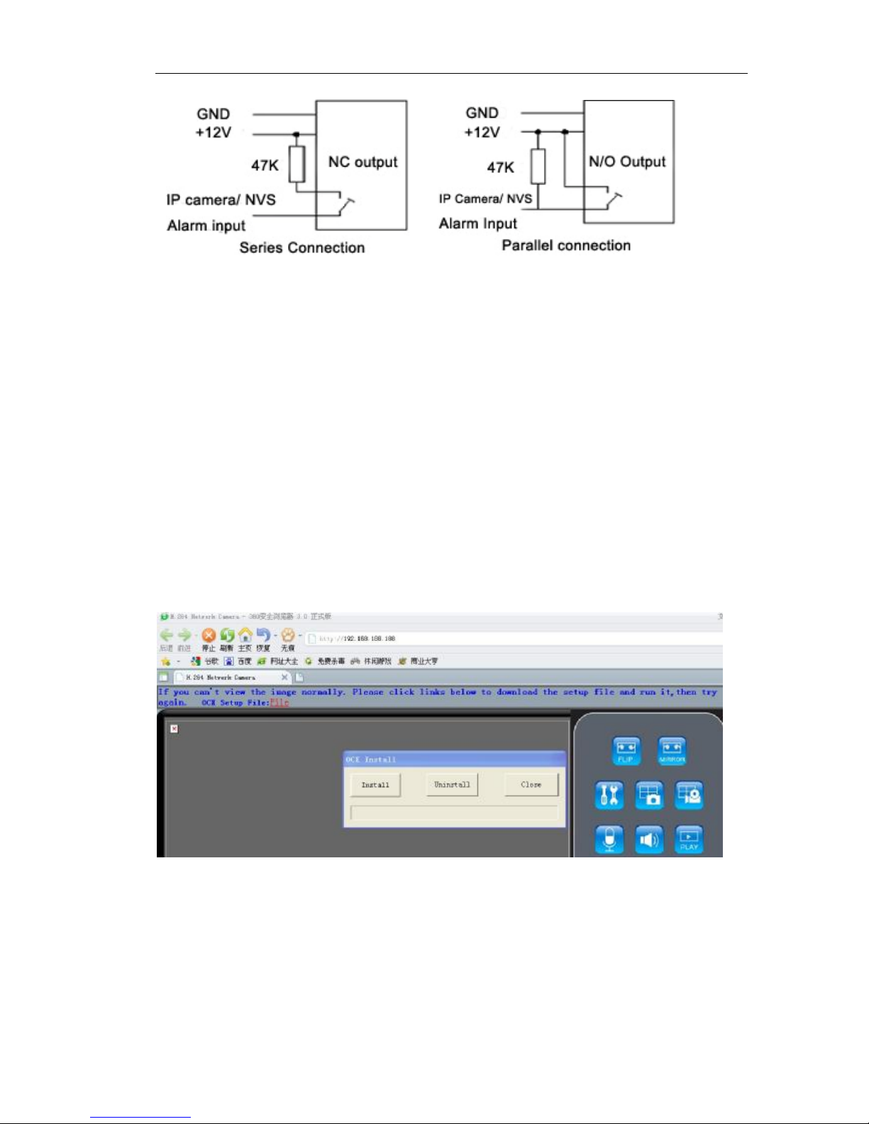
4.1.6.2 connect alarm (optional)
Connect alarm input and alarm output (connect or not according to the requirements
of the projects)
There are two ways to connect between video server and alarm box:
Page 14 of 95
4.1.6.3 SD Card(optional)
Insert SD card into SD card slot when power off. Don’t support hot swap the SD card.
Connect TX+ of PTZ unit to 485+ of IP camera, connect TX- of PTZ unit to 485- of IP
camera.
4.2 Software Installation
4.2.1 Using Web Browsers
1 Launch your web browser (Microsoft Internet Explorer). Check your Internet Explorer
version is 6.0 or above version. If not, please update your IE to the higher version.
2 Enter the IP address of Ip camera in the address field. Press Enter
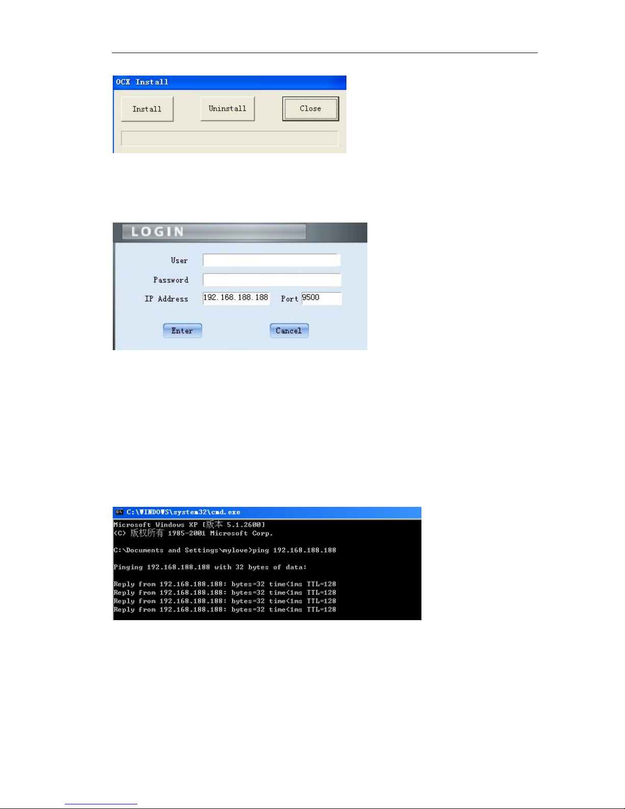
3 it appears OCX Install dialog as follows:
Click 『Install』to install the OCX.
4 If it doesn’t pop up the OCX install dialog, Click 『File』to download the OCX.
5 It will pop up a new dialog, click 『Run』 or 『Save』 to download OCX. After
download it , double-click the downloaded file “DVSClientx.exe” to install it.
Page 15 of 95
5 Refresh your web browser
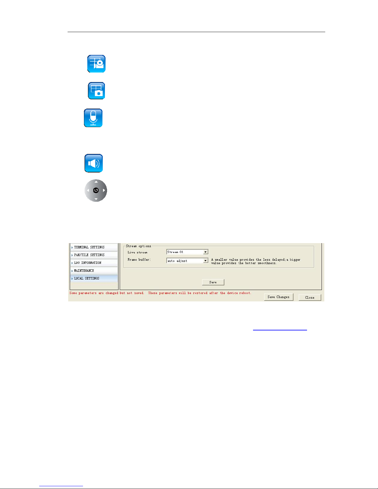
6 Enter the IP address.
It will ask for the password and user name.
Input user name: admin(default setting for administrator)Input password: admin
(default setting for administrator)
IP address
A Default IP address is 192.168.188.188,Subnet mask is 255.255.255.0. Please modify the
network parameter of Client PC. And make Client PC and Video Server in same
network segment. E.g.: your network IP address should be 192.168.188.x.
B Test the IP camera or NVS connect or not as follows:
In WINDOWS, click<Start→run→cmd , you can see the DOS window and input
“192.168.188.188”. That proves IP camera or NVS is working if the mention is same to
above picture.
4.2.1.1 Live view over IE
In the Liveview interface, User can do the operations as snapshot, record,
Page 16 of 95
talk,pan tilt zoom control.
Click to start manual record, and re-click to stop manual record.
Click to capture and save still images.
Click to talk to people around the IP camera. Audio will project from the
external speaker connected to the IP camera. Click this button again to end talking
transmission.
Click to turn on/off the volume on the local computer.
Click to control PTZ.Turn up, down, left, right, Automatic, call preset, set
preset point.
4.2.1.2 Live view setting
『Live Stream』Live stream can be setted to Stream 01 mode or Stream 02 mode.
OMC-900IP Series IP Camera support dual streaming for live view, local storage and
network transmission. As the dual stream setting, you can refer 5.1.1 Video setting
4.2.2 CMS Installation
4.2.2.1 PC requirements
Basic Configuration of Client PC
Motherboard: Pentium 2.8GHz
Memory: 512M
Display Card: TNT2
Recommended Configuration of Client PC
Motherboard: Dual-core 2.6GMhz
Page 17 of 95
Memory: 1G
Display Card: George FX5200 or ATI 7000(9000) Series 256MB
4.2.2 CMS Installation
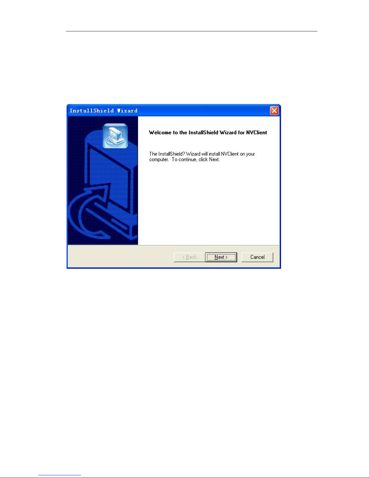
Run setup on windows, double click your left mouse button, it will be a “installation
wizard” dialogue box, as following figure:
Click “next”, there will be a dialogue box:
Page 18 of 95
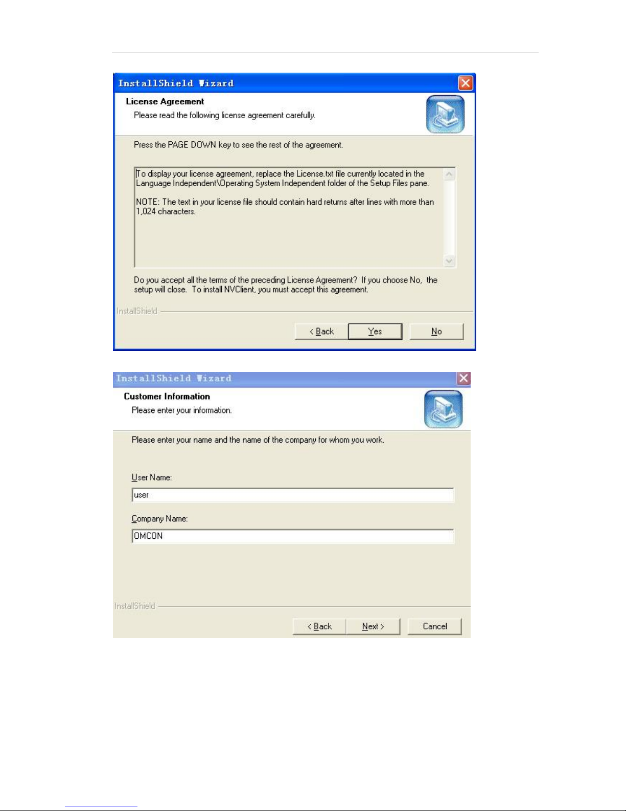
Click “Yes”, there will be a dialogue box:
Input user name and company name (optional), click “Next”, there will be a dialogue
box:
Page 19 of 95
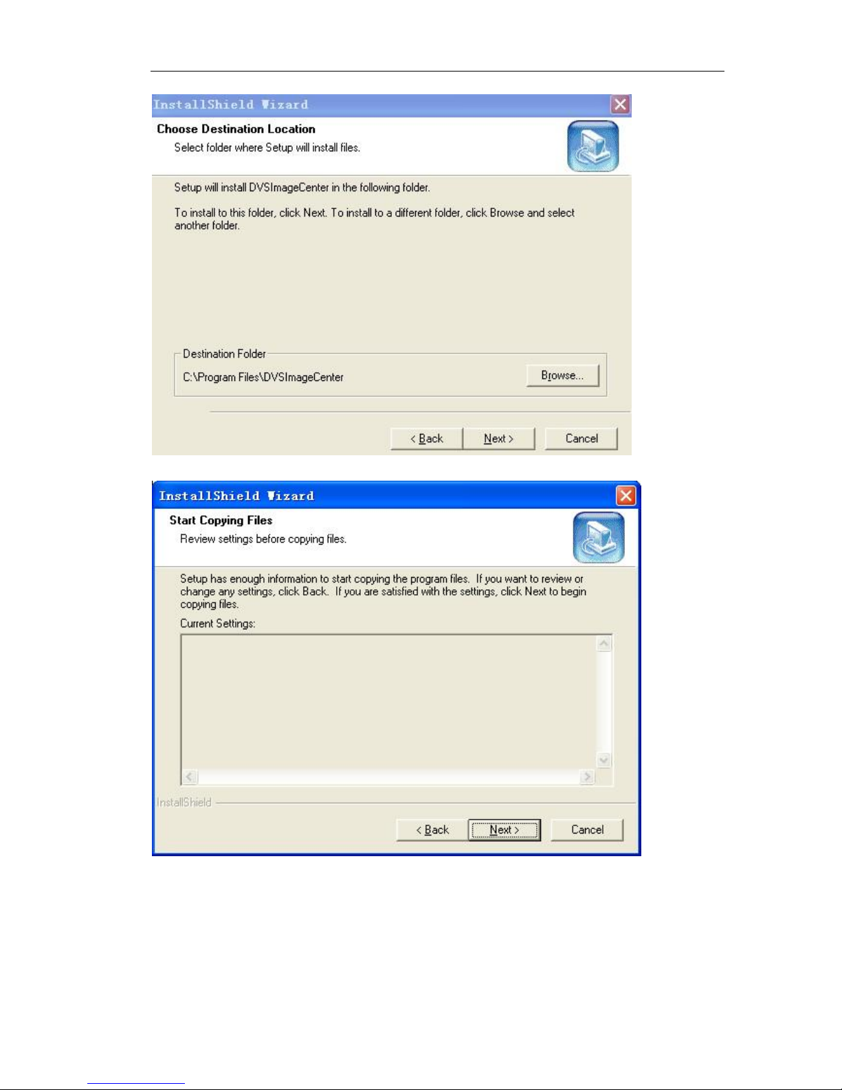
Choose installation folder, click “next”, there will be a dialogue box:
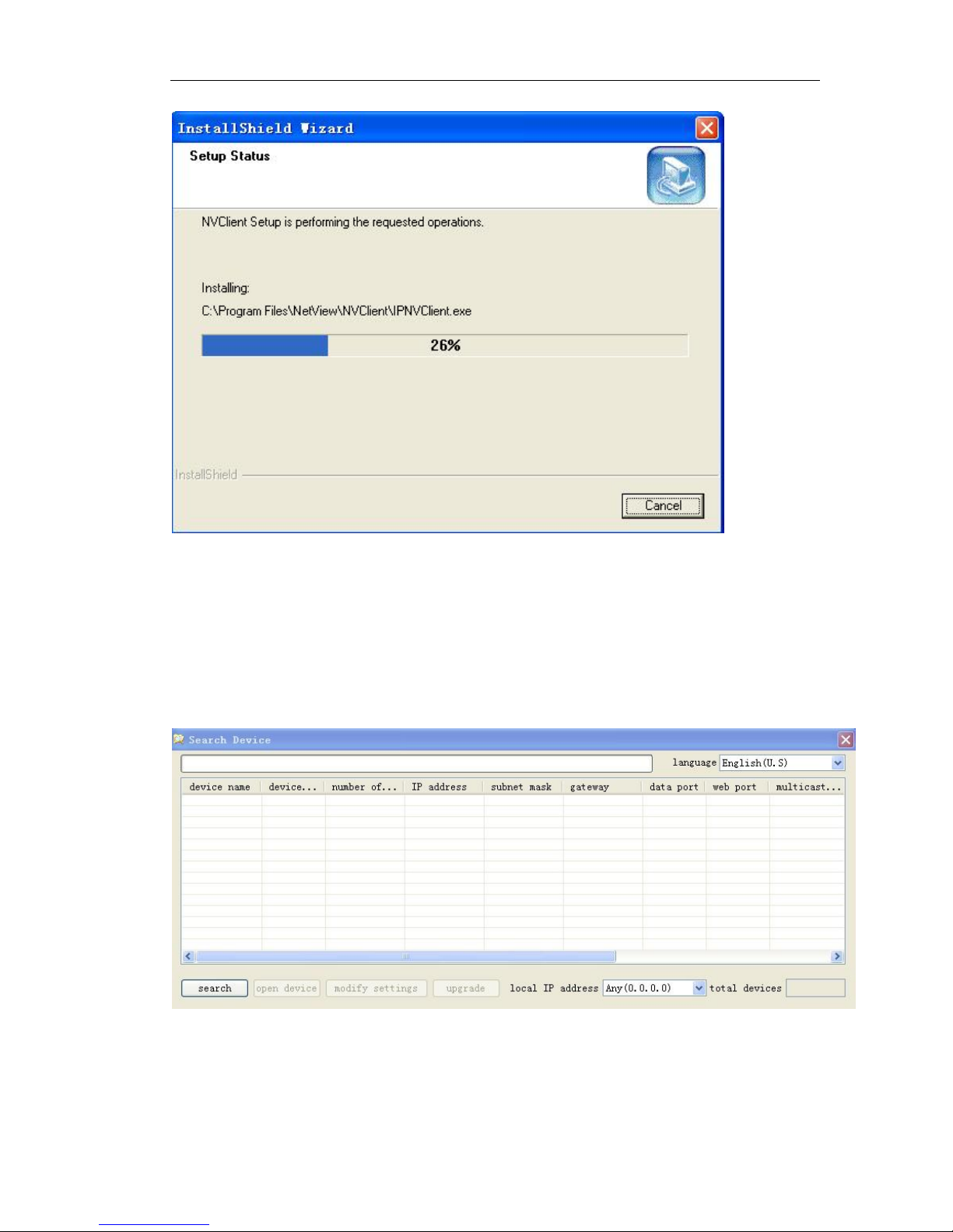
Click “Next”, move to the installation process
Page 20 of 95
When the installation is finished, there will be a dialogue box
Click “continue” and finish the installation
CMS is installed into the system default directory and there will be a “DVSImageCenter”
program group on the “Start”à”Program” of the windows system
4.2.3 How to obtain IP address?
After install the CMS, click 『Start』『 Program』『 Search』
Pops up the following figure
Click “search”, you can know the IP address of all IP cameras which connected in the
network. Make sure each IP camera has one individual IP address.

Page 21 of 95
4.3 IP Surveillance System Connection
Setting up the IP camera over the Internet
This section explains how to setup the IP camera to an Internet connection.
1 If you have external devices such as sensors, sound pick-up, speaker, Pan tilt unit,
make the connection.
2 Connect the IP camera to a switch by Ethernet cable
3 Connect the power calbe from IP camera to a power outlet.
There are several ways to set up the IP camera over the Internet. The first way is to set
up the IP camera behind a router. The second way is to use PPPoE.
Internet connection by a router
Before setting up the IP camera over the internet, make sure you have a router and
follow the steps below.
1 Connect your IP Camera behind a router, the internet environment is illustrated below.
Regarding how to obtain your IP address, please refer 4.2.3
2 If LAN IP address of your IP camera is 192.168.188.188, please forward the following
ports for the IP camera on the router
WEB Port and Data Port
If you have changed the port numbers on the Network page, please open the ports
accordingly on your router. For information on how to forward ports on the router,
please refer to your router’s user’s manual.
3 Find out the public IP address of your router provided by your ISP (Internet Service

Page 22 of 95
Provider). Use the public IP and the secondary HTTP port to access the IP camera from
the Internet.
Internet connection by PPPoE (Point-to-Point over Ethernet)
Choose this connection type if you are connected to the Internet by a DSL Line. Please
refer for 5.3.2 PPPoE details
5 IP camera configuration
There are following types of OMC-900IP network camera parameter configuration:
1) Set IP camera parameter via management software
2)Set IP camera parameter via IE
OMC-900IP Network Camera supports remote view, parameter setting and remote
control via software and IE
Use configuration tool
When you login the server successfully with IE, you can use the convenient
configuration tool provided by us to configure the Network Camera. Click
“ parameter setting” with left mouse button, configuration tool will pop-up a
new page, displayed as following:
5.1 video and audio settings (General, OSD display, Audio
Setting)
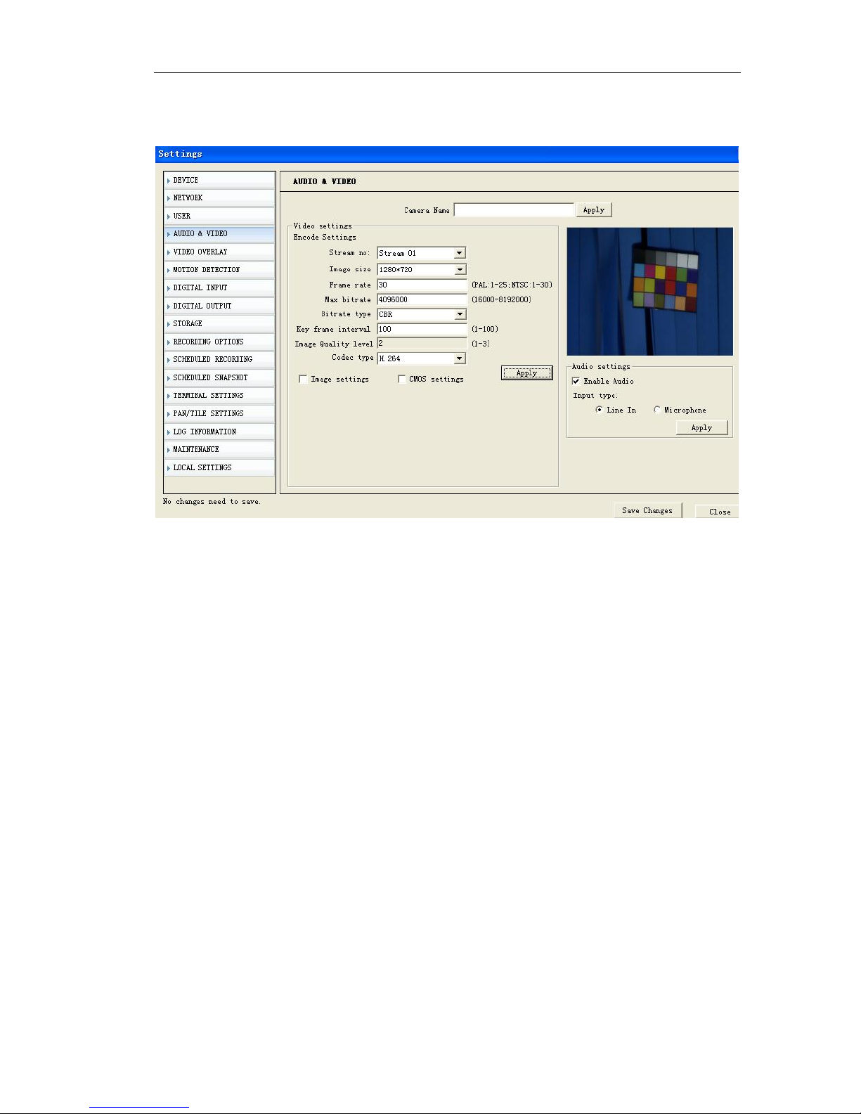
5.1.1 Video setting
Video setting includes the image size(resolution),Frame Rate, key Frame interval,
compression format, dual streaming and bit rate settings. (Details are described in the
next part “advanced image setting skills”)
『Video Format』Image setting. It is adjusting the resolution, please refer to the table:
Resolution Image size Frame rate (Max)
2Megapixel 1600*1200 15FPS
1.3Megapixel 1280*720 30FPS
VGA 640*352 30FPS
QVGA 320*176 30FPS
Page 23 of 95
Note: 2Megapixel and 1.3Megapixel are available for OMC-900IPMEGA Series
Megapixel IP camera.
『Stream no』You can define dual sreaming for local storage and network transmission.
Stream 01 is for local storage . Stream 02 is for network transmission.
If you don’t set stream 02, stream 01 can work both local storage and network
transmission.
『 Image size 』 If stream 01 mode, the resolution can be setted to 1600*1200
(2megapixel); 1280*720(1.3Megapixel)
If stream 02 mode, the resolution can be setted to 640*352 (VGA); 320*176 (QVGA)
『Frame Rate』It means how many frames the encoder is encoding per second. For
details please refer to table 1.
『Key Frame Inv』It means the number of frame P or frame B between key frames
(frame I)
『Rate Type』When the VBR(Variable Bit rate) is chose, the Network Camera will
automatic choose a proper stream according to the complex and movement
condition of images and the image quality set by user, but the “stream rate” will not
exceed. When the CBR (Constant Bit rate) is chose, the Network Camera will control
the “stream rate” in the setting.
『Image Quality level』It is an important parameter that controls image quality, it can
be set in 3 levels. For setting please refer to “advanced image setting skill”
『Bit Rate』“Bit Rate” means the amount of stream bit encoding by encoder in a
second, the unit of stream rate is bps, namely bits per second. The range of stream rate
is from 16k to 8192k, please note that the unit k means 1000, for example 8192k means
8192000bps, the encoder will use 819200bps stream rate to encode video.

Page 24 of 95
For more details of setting of the above part please refer to the following “advanced
image setting skill”
『Code type』Support dual compression, H.264 or MJPEG.
Advanced image setting skill
Image setting is an important part in the server setting because it will affect the
system ability, it has close relationship with the video quality and network ability. The
aim of image setting is to make it conveniently suitable for various networks.
Bit stream and frame rate settings are providing in system, but it is hard to suit various
networks with only several default values. Consequently, some advanced settings are
providing for user to ensure the video quality while utilizing network effectively.
The image settings including 『Bit Rate』,『Frame Rate』,『Key Frame Inv』,『Rate
type』and『Image Quality level』are what we concern about.
Now we will introduce meaning, effect to other settings and network ability of each
setting respectively.
Bit Rate
It means the size of stream bit encoding by encoder per second. The unit is bit per
second. this setting is the main factor affects the bandwidth of network and other
settings. The bandwidth utilizing will increase when the bit rate increase. Thus CBR
(Constant Bit rate) setting according to the bandwidth is suitable for the network
bandwidth limitation situations. In the same quality situation, bit rate will be affected by
settings frame rate, I frame Inv, rate type, image quality, and definition. Please refer to
following introduction for details. This parameter is valid when the “Rate Type” is set as
CBR (Constant Bit rate).
Frame Rate
It means the maximum number of frames that encoder encode per second, with unit
frame per second. This setting has three functions, firstly the number of frames encoder
encoding per second is set by this setting, secondly when the stream rate is CBR
(Constant Bit rate), when the frame rate changed, for example decreased, because
the encoder need to keep the current code stream setting, thus it will enhance the
frame quality according to the current code stream setting. It means, when the code
stream is VBR (Variable Bit rate), the decreasing of frame rate will enhance the quality
of video and keep the same frame rate value. The video quality will reduce conversely.
Thirdly, when the same quality is kept, the increasing frame rate will make the image
smoother and stream rate increasing. Conversely, the image will become
discontinuous and stream rate decrease.
Key Frame Inv
It means the number of frame P or frame B between key frames (frame I). Generally,
the default value of this parameter is 25 and does not need to be changed. When the
stream rate is settled, the increasing of this value will make the quality of video better.
When the video keeps the same quality, this value increasing will make stream rate
increased. Conversely, the stream rate will decrease.
Rate Type
When the VBR (Variable Bit rate) is chose, the front end will automatic choose a proper

Page 25 of 95
stream according to the complex and movement condition of images and the image
quality set by user, but the “Bit Rate” will not exceed. When the CBR (Constant Bit rate)
is chose, the front end will control the “Bit Rate” in the setting.
Image Quality
It is an important parameter that controls image quality, this parameter is valid when
the “Rate Type” is set as VBR (Variable Bit rate).
To sum up, please refer to our reference value for various conditions and the
information giving above to adjust the image setting. You can make adjusting
according to the above description if the quality of video is not satisfied.
Reference
setting
Attribute
Frame
rate
Rate type Bit rate Stream mode
CBR
(Constant Bit
rate)
CBR
(Constant Bit
rate)
25
CBR
(Constant
Bit rate)
Set
according
condition
Set
according
condition
LAN
VBR
(Variable Bit
rate)
25
VBR
(Variable Bit
rate)
Unlimited
Stream 01 or
stream 02
ADSL- upload
512k
CBR
(Constant Bit
rate)
12
CBR
(Constant
Bit rate)
384k Stream 02
ADSL-upload
1M
CBR
(Constant Bit
rate)
12
CBR
(Constant
Bit rate)
512k Stream 02
ADSL-upload
2M
CBR
(Constant Bit
rate)
25
CBR
(Constant
Bit rate)
768k Stream 02
Best
VBR
(Variable Bit
rate)
25
VBR
(Variable Bit
rate)
Unlimited
Set
according
condition
Good
VBR
(Variable Bit
rate)
25
VBR
(Variable Bit
rate)
Unlimited
Set
according
condition
Normal
VBR
(Variable Bit
rate)
25
VBR
(Variable Bit
rate)
Unlimited
Set
according
condition
Notice: pleas slightly adjust values referring to above reference values according to
the system condition. You can make necessary adjusting according to the description
of each setting if you have strict requirements for the image quality and bandwidth.
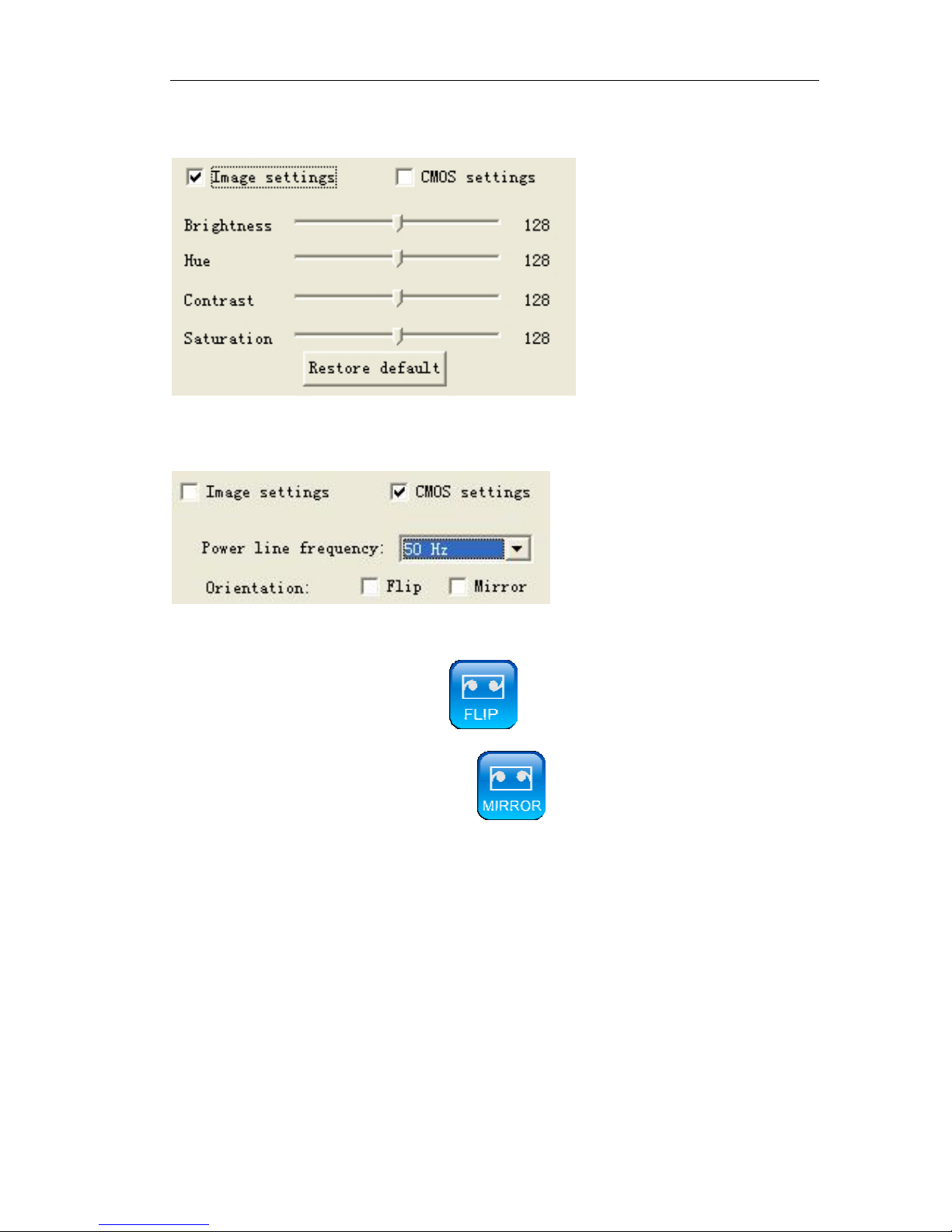
5.1.2 Image setting
『Image setting』Image setting includes the brightness, contrast and Hue. The left of the
setting bar is the minimum value, you can easily drag the bar control to change value
Page 26 of 95
by mouse. Click 『Restore default』to load the factory settings.
5.1.3 Video Flip and Mirror
『Power line frequency』For different countries, it has different frequency. If image
flickers, may the setting of power line frequency is not correct
『Flip』 vertical reversal or click
『Mirror』horizontal reversal or click
After setting, click the 『apply』button.
5.1.4 Audio setting
『Enable Audio』Clicking “√” on “□”in the “Enable Audio” means the system will
encode audio and send encoded audio stream to the client via network.
If audio device is microphone, click 『Microphone』.
If audio device is line in, choose 『line in』.
After setting, click 『Apply』 button.
Page 27 of 95
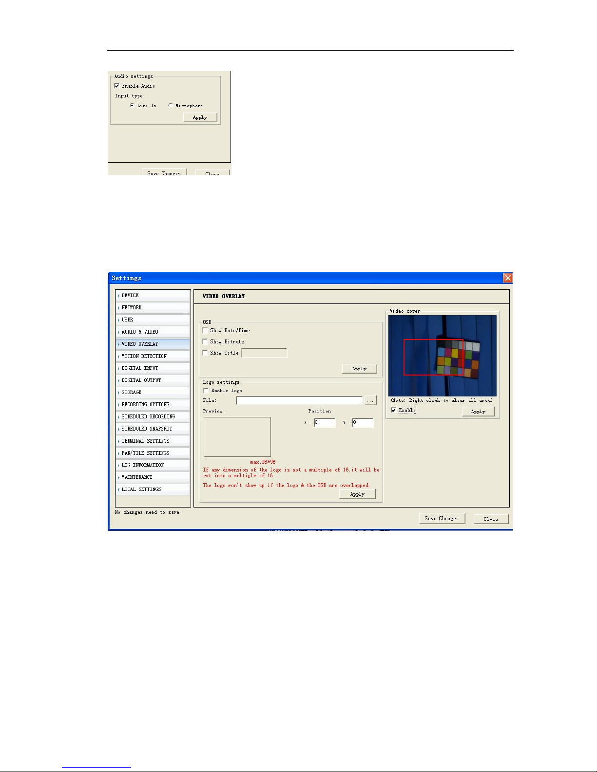
5.2 OSD/MASK setting
The “OSD setting” shown as following figure includes the OSD/MASK setting. In the
setting “√” in “□” means enable the corresponding overlay option function, contrarily
disable the corresponding function.
『OSD』This setting achieves the characters overlay function, including date overlay,
time overlay, channel description overlay, frame rate and bit rate display. They are
displayed on the top left of the live view video.
『Video Cover』: This setting achieves the video mask setting function on specific zone.
『Enable』Drag the left button of mouse to draw a zone where you would like to shelter
on the image and click 『Apply』. If you would like to cancel the shelter setting, no need
click “√” in “□” .
Page 28 of 95
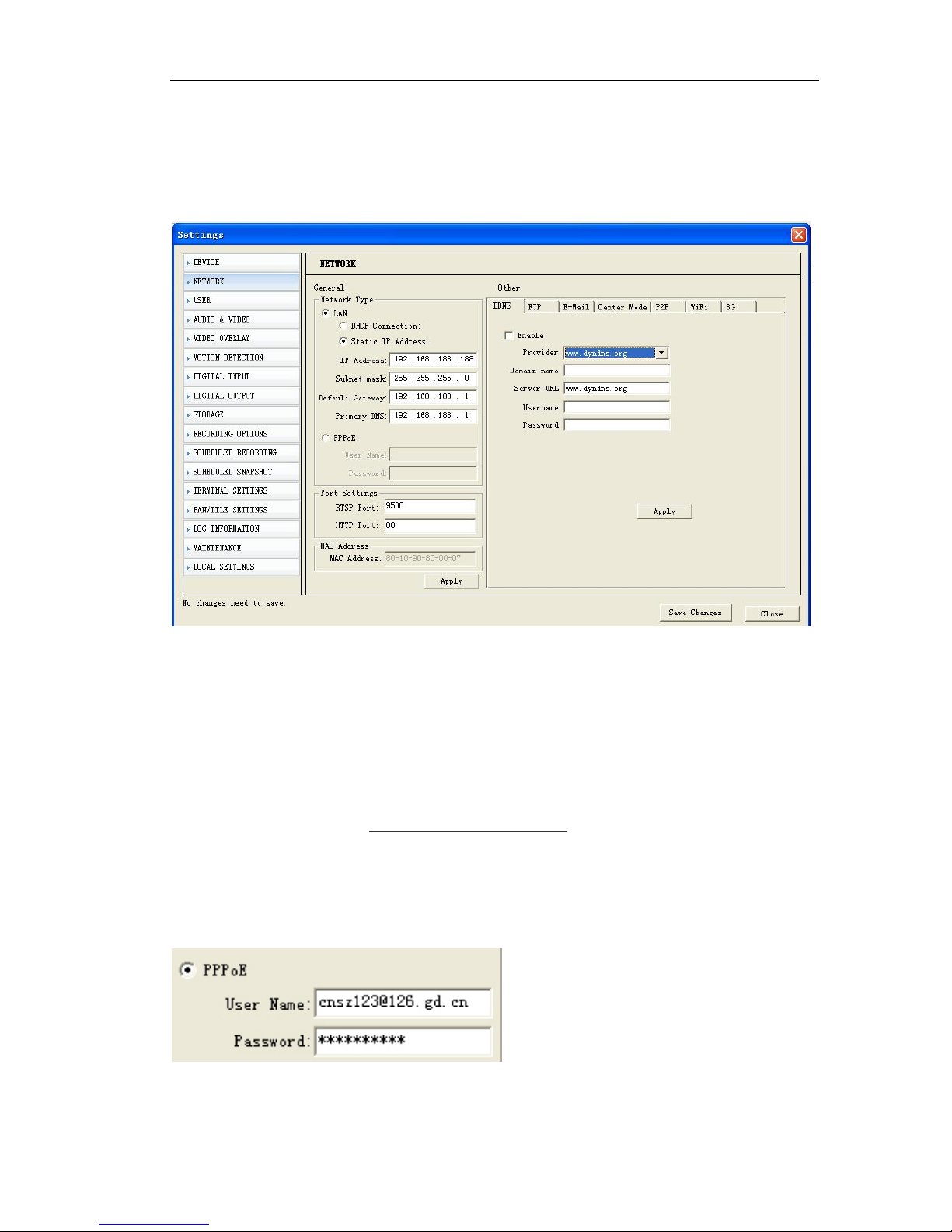
5.3 network settings (General, PPPoE,DDNS, FTP, E-mail, Wifi, 3G)
5.3.1 General setting
『IP address』IP address is the address of Network Camera in network, please enquire
this value from your network administrator, invalid or address conflict will cause Network
Camera connection failed. Default IP address is 192.168.188.188
『Subnet mask』、『 Gateway』Please enquire your network administrator.
『DNS』Please enquire your network administrator.
『RTSP Port』it is the listening port providing data servers including video and audio
stream service and setting service.
『HTTP port』it is the listening port providing web service. If this setting is changed,
please login by accessing http://IP address: web port
『Apply』Click this button when you finished corresponding setting options.
5.3.2 PPPOE
If IP Camera or video server connect it to ADSL modem directly, please set the PPPoE
here.
Page 29 of 95
Enable PPPoE, enter user name and password (get it from local ISP) for PPPoE account
authentication.
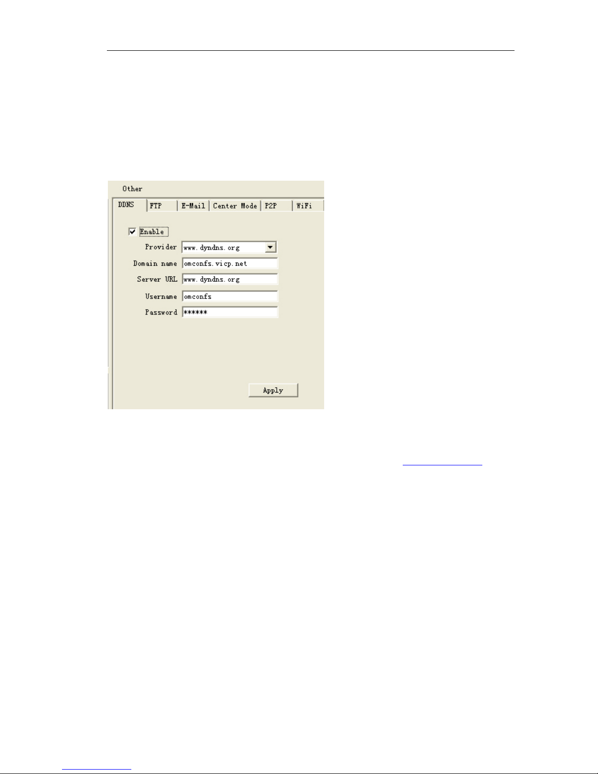
5.3.3 DDNS
A dynamic DNS (domain name system) service that allows your IP camera, especially
when assigned with a dynamic IP address, to have a fixed host and domain name.
『Enable』:Select this opton to enable the DDNS setting
Provider: Select a DDNS provider from the provider drop-down list
Make sure that before utilizing this function, please apply for a dynamic domain
account first. You apply for a dynamic domain account to visit www.dyndns.org.
『DDNS User Name』User registered in DDNS server
『DDNS Password』User Password in DDNS server.
『DDNS Domain Name』The Domain Name set for long-distance controlling after user
logon in DDNS server.
『DDNS Address』When the DDNS address is the domain Name, please set the DNS
address correctly.
Note:
The default DNS address is Guangdong China DNS address. If users are in
other regions to use DDNS function, please set the correct DNS address for the
device same as the user local DNS address.
『DDNS Port』Default :30000.
『Data Port Forwarding』When the device mapped to TCP/IP through network server, fill
in the TCP/IP data port forwarding number.
『WEB Port Forwarding No』 When the device mapped to TCP/IP through network
server, fill in the TCP/IP WEB port forwarding number.
 Loading...