


Silver
Stream-In / Stream-Out
RCA/XLR version
User manual
System Release 1.5.2 | Document Version 0.9.9 | release/update: April 2015

Silver Stream-In / Stream-Out - System Release 1.5.2 – April 2015
Page 2
Whiterock Business Park - 729 Springfield Road - Belfast BT12 7FP - Northern Ireland
Tel.: +44 28 9067 7200 | Fax: +44 28 9067 7201 | www.aptcodecs.com | contact@aptcodecs.com
DECLARATION OF CONFORMANCE
Established following the Directives 99/5/EC and 2006/95/EC
We, hereby, certify that Silver Stream-In / Stream Out complies with the dispositions of the European
Community Directive for harmonized standards within the Member States related to radio equipment
and telecommunications terminal equipment (Directive 99/5/EC) and low voltage (Directive
2006/95/EC).
This is a Class A product. In a domestic environment this product may cause radio interference, in which case the user may be required to take adequate measures.
Installation and Operational Manual:
Silver Stream-In / Stream-Out User Manual
System Release 1.5.2 paired with NMS #1183 / April 2015
© Copyright 2011/2015 by WorldCast Systems. All rights reserved.
No part of this publication is permitted to be reproduced, stored in a retrieval system, transmitted by
any means, electronically, mechanically or otherwise, without written consent of WorldCast Systems.
Warranty
All information is believed to be true and correct at time of print. WorldCast Systems reserves the
right to make any changes, without notification, to their products and manual.
WorldCast Systems makes no warranty of any kind with regards to this material, including the implied
warranties of merchantability and fitness for a particular purpose.
WorldCast Systems shall not be liable for errors contained herein or for incidental or consequential
damage in connection with the furnishing, performance or use of this material.
Trademarks
Apt-X® and Enhanced apt-X® are registered trademarks of CSR. Other trademarks are the property of
their respective owners.

Silver Stream-In / Stream-Out - System Release 1.5.2 – April 2015
Page 3
Whiterock Business Park - 729 Springfield Road - Belfast BT12 7FP - Northern Ireland
Tel.: +44 28 9067 7200 | Fax: +44 28 9067 7201 | www.aptcodecs.com | contact@aptcodecs.com
How to contact us:
WorldCast Systems Head Office
20, avenue Neil Armstrong - Parc d'Activités J.F. Kennedy
33700 BORDEAUX – MERIGNAC
FRANCE
Tel: +33 (5)57 928 928 | Fax: +33 (5)57 928 929
Americas Office
19595 NE 10th Ave, Suite A
Miami FL 33179
USA
Tel: +1 (305)249 31 10 | Fax: +1 (305) 249 31 13
How to get support
If you have a technical question or issue with your APT equipment, please consult the support section of our website at:
http://www.aptcodecs.com
or apt-cust-support@worldcastsystems.com

Silver Stream-In / Stream-Out - System Release 1.5.2 – April 2015
Page 4
Whiterock Business Park - 729 Springfield Road - Belfast BT12 7FP - Northern Ireland
Tel.: +44 28 9067 7200 | Fax: +44 28 9067 7201 | www.aptcodecs.com | contact@aptcodecs.com
Table of Contents
This is the main table of contents of the entire User Manual. It presents the main topics
of each section of this document.
Safety & Disposing Information 8
About this Manual 9
1.0
1.1 Release Notes 9
1.1.1 System Options for SR.1.4.2: 9
1.2 Company Profile 10
1.3 Unpacking and Inspection 11
1.4 Introduction 12
1.4.1 System Options 13
1.5 Getting Connected 14
1.6 The WorldCast Codec Management System - Overview 15
1.6.1 Installing the Network Management System 17
1.6.2 Getting Started 19
1.7 Codecs and Switches 21
Installation and Wiring 23
2.0
2.1 Pre-Installation Notes 23
2.1.1 Tools and Cables Required 23
2.1.2 Front panel Components 24
2.1.2.1 Monitoring 24
2.1.2.2 Power- Connection - and Alarm Status 24
2.1.2.3 Reset Switch – Default IP Addresses 24
2.2 Wiring Information 25
2.2.1 Power Adaptor – DC In 25
2.2.2 Ethernet Interface 25
2.2.3 Audio Inputs and Outputs on XLR version 26
2.2.4 Audio Inputs and Outputs on RCA version 26
2.2.5 Auxiliary Data Interface 27
2.2.6 Ethernet Interface 27
WorldCast/Silver WEB-Browser GUI 28
3.0
3.1 The WorldCast WEB GUI - Overview 28
3.1.1 WEB GUI – Technical Requirements 28
3.1.1.1 Browser Cache 28
3.1.2 WEB GUI - Default Network Settings 29
3.2 WEB GUI - Getting Started 29
3.2.1 WEB GUI - Default LogIn 29

Silver Stream-In / Stream-Out - System Release 1.5.2 – April 2015
Page 5
Whiterock Business Park - 729 Springfield Road - Belfast BT12 7FP - Northern Ireland
Tel.: +44 28 9067 7200 | Fax: +44 28 9067 7201 | www.aptcodecs.com | contact@aptcodecs.com
Table of Contents
3.2.2 Loading and Locking 30
3.2.3 Additional Status Indications 31
3.2.3.1 Activated Licenses 31
3.2.3.2 CPU Utilization 31
3.2.4 Status Page 32
3.2.5 Session Close/Session Time Out 32
3.2.6 Main Menu 33
3.3 Main Menu - Status 34
3.3.1 Current Status Frame 36
3.3.2 Alarm Status 37
3.3.3 Performance Monitor 39
3.3.3.1 IP Statistics – Details 40
3.3.3.2 IP Statistics – Receive Buffer Level 40
3.3.3.3 About Stream Tables (general) 41
3.4 Main Menu – Connection 42
3.4.1 Quick Connection Error! Bookmark not defined.
3.4.2 Profile Wizard - Creating a Profile 44
3.4.3 Profile Wizard – Codec Settings 45
3.4.3.1 Encoder Settings Error! Bookmark not defined.
3.4.3.2 Decoder Settings 46
3.4.4 Embedded AUX Data Error! Bookmark not defined.
3.4.5 Connection Wizard – IP Streams Configuration 47
3.4.6 IP Stream Configuration - general 49
3.4.6.1 About Stream Types 50
3.4.7 Audio Stream Configuration 51
3.4.7.1 Transmit (Tx) Stream-In 51
3.4.7.2 About Packet Sizes 53
3.4.7.3 Receive (Rx) Stream-Out 54
3.4.7.4 AUX data Stream Configuration (Tx) 55
3.4.7.5 About Packet Size of AUX Data Streams 57
3.4.7.6 IP Forwarding 57
3.4.7.7 Receive Audio Stream, Decode and Forward 58
3.4.7.8 Forwarding an IP Stream (Tx) 60
3.4.8 Profile Wizard – Saving a Profile Error! Bookmark not defined.
3.4.9 Connection – Advanced Configuration 62
3.4.10 Connection – Validation Engine 64
3.5 Main Menu – System 66
3.5.1 Date and Time 66

Silver Stream-In / Stream-Out - System Release 1.5.2 – April 2015
Page 6
Whiterock Business Park - 729 Springfield Road - Belfast BT12 7FP - Northern Ireland
Tel.: +44 28 9067 7200 | Fax: +44 28 9067 7201 | www.aptcodecs.com | contact@aptcodecs.com
Table of Contents
3.5.2 User Management 67
3.5.3 Network Settings 67
3.5.3.1 Network Page 67
3.5.3.2 Dynamic DNS 69
3.5.3.3 NAT Traversal Mode – UPnP 71
3.5.4 mDNS Server – Look Up 72
3.5.5 Diagnostics 72
3.5.6 SMTP (Mail Setup) 73
3.5.7 SNMP 74
3.5.7.1 SNMP Agent 75
3.5.7.2 SNMP Trap Management 76
3.5.7.3 SNMP Notifications Management 77
3.5.8 System – ScriptEasy 78
3.5.8.1 About ScriptEasy 78
3.5.8.2 ScriptEasy – Script Example 79
3.5.8.3 ScriptEasy – Configuration 79
3.5.8.4 ScriptEasy – Remove a Script 80
3.5.9 Event Log 81
3.5.9.1 Event Log Export 82
3.5.9.2 Event Log History 83
3.5.10 (Firmware) – Update 84
3.5.11 Licenses 84
3.5.12 System 85
3.5.12.1 Chat Box 86
3.6 Main Menu – Configuration 87
3.6.1 Audio Configurations 87
3.6.1.1 Audio Configuration Options 89
3.6.1.2 Advanced Routing & Decoder Mono Mode 91
3.6.2 Network Alarms 92
3.6.3 AUX Data Configuration 93
3.6.4 Alarms Configuration 94
3.6.5 Alarms - Customer Alarms 95
SureStream 96
4.0
4.1 About SureStream 96
4.1.1 SureStream Encoder 98
4.1.2 SureStream Decoder 98
4.2 SureStream – Encoder Configuration 99

Silver Stream-In / Stream-Out - System Release 1.5.2 – April 2015
Page 7
Whiterock Business Park - 729 Springfield Road - Belfast BT12 7FP - Northern Ireland
Tel.: +44 28 9067 7200 | Fax: +44 28 9067 7201 | www.aptcodecs.com | contact@aptcodecs.com
Table of Contents
4.2.1 About Diversity Generator Levels 100
4.2.2 Creating a Set of Component Streams 101
4.3 SureStream – Decoder Configuration 102
4.3.1 SureStream – Decoder Performance 104
System – Firmware Update 105
5.0
5.1 About – System Firmware 105
5.1.1 Firmware Update – Step 1 105
5.1.2 Firmware Update – Step 2 106
5.1.3 Firmware Update – Step 3 107
5.1.4 Firmware Update – Step 4 108
5.1.5 Firmware Update – Step 5 109
5.1.6 Firmware Update – Step 6 110

Silver Stream-In / Stream-Out - System Release 1.5.2 – April 2015
Page 8
Whiterock Business Park - 729 Springfield Road - Belfast BT12 7FP - Northern Ireland
Tel.: +44 28 9067 7200 | Fax: +44 28 9067 7201 | www.aptcodecs.com | contact@aptcodecs.com
Safety & Disposing Information
The Silver Stream-In / Stream-Out IP-Audio devices are powered by an external switching
power adapter. If a product defect occurs on the power adapter this adapter must be replaced. There are no user-serviceable parts inside.
TO PREVENT THE RISK OF ELECTRIC SHOCK, DO NOT OPEN THE COVER OF THE POWER
ADAPTER THERE ARE NO USER-SERVICEABLE PARTS INSIDE THIS UNIT. PLEASE REFER
SERVICING TO QUALIFIED APT SERVICE PERSONNEL.
According to local laws and regulations this product should not be disposed of in the household waste but sent for recycling.

Silver Stream-In / Stream-Out - System Release 1.5.2 – April 2015
Page 9
Whiterock Business Park - 729 Springfield Road - Belfast BT12 7FP - Northern Ireland
Tel.: +44 28 9067 7200 | Fax: +44 28 9067 7201 | www.aptcodecs.com | contact@aptcodecs.com
About this Manual 1.0
Thank you for purchasing the Silver Stream-In/Stream-Out audio Codec from APT. We have
developed these units to be as user friendly as possible, and they contain many advanced
features which are designed to make the use of this product simple and straightforward.
This operations manual is intended for operators of the Silver Stream-In/Stream-Out audio
network transmission link. This manual describes the function, the installation and use of the
unit.
It is recommended that new users of the Silver Stream-In/Stream-Out should read the full
manual before switching it on for the first time, to get a better feel for the functionality and
to eliminate any possible area of confusion.
1.1 Release Notes
This manual is the primary reference covering the configuration, installation, operation and
troubleshooting of the Silver Stream-In/Stream-Out.
As of this publication date, this document is the current manual revision. We recommend
that you check with your distributor or on the APT website for updates to firmware and this
manual.
This Manual refers to System Release 1.5.2 – April 2015
1.1.1 System Options for SR.1.5.2:
Optional ScriptEasy version 2.6.1.001
Optional MasterView version 1.4.20.001
1.2 Important Security Advices
1.2.1 This IP Audio Codec is a network device!
For further information, please also refer to section 1.8.
Before commissioning, we strongly recommend to change the default LogIn on the WEB
GUI (refer to section 3.5.2)!
Before connecting to your Network, please check the SNMP community strings. Don’t use
the trivial default names (refer to section 3.5.7.1)

Silver Stream-In / Stream-Out - System Release 1.5.2 – April 2015
Page 10
Whiterock Business Park - 729 Springfield Road - Belfast BT12 7FP - Northern Ireland
Tel.: +44 28 9067 7200 | Fax: +44 28 9067 7201 | www.aptcodecs.com | contact@aptcodecs.com
1.3 Company Profile
WorldCast Systems is a highly respected provider of professional, reliable and innovative solutions to the Radio & TV industry worldwide.
Encompassing the industry-leading brands of APT, Ecreso and Audemat, WorldCast Systems
offers high-performing broadcast systems including audio codecs, FM transmitters and RF
signal monitoring designed to meet the needs of both large international broadcast networks
and small private stations alike. WorldCast Systems’ products are deployed throughout the
networks of many major public and commercial broadcasters such as the BBC, ARD, the
EBU, RTE, TDF, RNE, Teracom, RAI, ORF and Clear Channel Radio
APT codecs deliver audio over IP, T1, ISDN & Leased Lines. Our award-winning
SureStream technology enables high quality audio transport over cost-effective IP links.
Ecreso offers highly efficient FM transmitters with extensive inbuilt functionality, highly
competitive Total Cost of Ownership and an industry-leading 10 year warranty.
Audemat provides a range of professional monitoring and measurement tools for Radio
& TV, complemented by an extensive range of remote control systems for management,
configuration and monitoring of broadcast networks.
Three core values have shaped the growth and direction of WorldCast Systems
1. Product innovation:
Audemat places a key emphasis on Research & Development and its innovative approach
has been repeatedly recognized by the industry. WorldCast Systems has won awards for
innovation at consecutive NAB Shows for over 10 years.
2. Customer satisfaction:
Audemat is dedicated to ensuring the best quality, value and service for its customers
and has achieved IS0 9001 certification.
3. Sustainable Development:
Audemat is committed to sustainable development and demonstrates this commitment in
several ways: it has been ISO 14001 certified since 2007, adheres to the UN Global
Compact project and all new products are developed in keeping with an eco-design philosophy and built within Audemat’s low energy consumption factory.
Headquartered in Bordeaux-Merignac, France, WorldCast Systems employs nearly 100 people worldwide with an R&D center in Northern Ireland and sales offices in the UK, Germany,
India and the US. A global distributor network works together with our international sales
and support staff to offer local assistance to our international customer base.

Silver Stream-In / Stream-Out - System Release 1.5.2 – April 2015
Page 11
Whiterock Business Park - 729 Springfield Road - Belfast BT12 7FP - Northern Ireland
Tel.: +44 28 9067 7200 | Fax: +44 28 9067 7201 | www.aptcodecs.com | contact@aptcodecs.com
1.4 Unpacking and Inspection
After unpacking:
Check the unit for damage during shipping. Immediately report any damage back to the
distributor or APT.
Check that the list of contents is complete as follows:
Silver Stream-In / Stream-Out
Serial Number located on the
rear panel:
Stream-In/RCA: I000-
Stream-Out/RCA: P000-
Stream-IN/XLR: K000-
Stream-Out/XLR: R000-
(please complete)
External Power Adapter
Please confirm that the local power supply voltage matches the required voltage levels of
100-240VAC
CD Box
A CD box including a Quick Start guide and a CD where you will find the documentation
for this product.
If the equipment supplied does not match the items requested please contact APT or your local distributor immediately and report any shortages.

Silver Stream-In / Stream-Out - System Release 1.5.2 – April 2015
Page 12
Whiterock Business Park - 729 Springfield Road - Belfast BT12 7FP - Northern Ireland
Tel.: +44 28 9067 7200 | Fax: +44 28 9067 7201 | www.aptcodecs.com | contact@aptcodecs.com
1.5 Introduction
The Silver audio Codec range is based on the new APT Codec core engine. This new engine is
designed to be as flexible and versatile in use as possible. The core is powerful and addresses more than ever the needs of professional IP audio transmissions.
The set of Silver Stream-In and Stream-Out can be used to setup a full duplex link. The Silver Codec range consists of the Encoder (Stream-In) and the Decoder (Stream-Out) as separate units in a ½ 1U format.
As a multi-algorithm audio Encoder or Decoder it is offering conventional analog left and
right audio connections operating through IP. These analog audio connections are carried out
for semi-professional phone jacks or as professional XLR connectors.
The new Codec generation incorporates the enhanced versions of the apt-X® algorithm (real
time transmission on the network with data reduction by factor 4:1,) Linear PCM 16 and 24
bit as well as MPEG 4 HE-AACv1/2.
The units are capable of delivering high quality audio used for inter-studio networking, remote/outside broadcasts and STL/TSL monitor applications.
Audio modes and bandwidths are dependent on the network bit rate, the algorithm, mode
and frequency response selected and the bit resolution of the desired audio.
The Silver Codec range runs an embedded WEB GUI which can be accessed from a web
browser or via the WorldCast Codec Management System which runs on a PC connected via
LAN or WAN. A headphone socket provides for additional monitoring of the audio input (Encoder) or the output (Decoder)
An Additional interface allows for the connection of auxiliary data terminated on a DB-9way
connector. Regardless of using the Encoder (Stream-In) or the Decoder (Stream-Out) the
AUX Data link is provided always as a duplex link (while the audio is always simplex).
The Silver Stream-In and Stream-Out come with the SureStream option applied as standard.
Both units are very similar with the exception that the Decoder offers an additional USB port
for future use (e.g. playing out stored audio files).

Silver Stream-In / Stream-Out - System Release 1.5.2 – April 2015
Page 13
Whiterock Business Park - 729 Springfield Road - Belfast BT12 7FP - Northern Ireland
Tel.: +44 28 9067 7200 | Fax: +44 28 9067 7201 | www.aptcodecs.com | contact@aptcodecs.com
1.5.1 System Options
The following soft- and hardware options are available:
ScriptEasy: A scripting language for enhanced management and control of a Codec de-
vice. In addition ScriptEasy allows the user to communicate and control external equipment using SNMP protocol GET/SET commands.
MasterView: it allows to create customized dashboards to be able remotely to check the
equipment status and to perform user remote actions
Advanced Audio Backup: playlist for USB stick & Play out from Shoutcast server (available in
later release)
Notes:
____________________________________________________________
____________________________________________________________
____________________________________________________________
____________________________________________________________
____________________________________________________________
____________________________________________________________
____________________________________________________________
____________________________________________________________
____________________________________________________________
____________________________________________________________
____________________________________________________________
____________________________________________________________

Silver Stream-In / Stream-Out - System Release 1.5.2 – April 2015
Page 14
Whiterock Business Park - 729 Springfield Road - Belfast BT12 7FP - Northern Ireland
Tel.: +44 28 9067 7200 | Fax: +44 28 9067 7201 | www.aptcodecs.com | contact@aptcodecs.com
1.6 Getting Connected
This chapter outlines how you can quickly connect your Silver Codec and start sending audio.
Begin by connecting the power adapter to the unit.
Making a connection and send audio:
Set up the Silver Stream-In Encoder and the transmitting IP stream
apply this configuration to the unit
Set up the Silver Stream-Out Decoder and the receiving IP stream
Apply this configuration to the unit
The audio connections are made on the rear panel using RCA phone jacks or XLR type connectors.
Stream-In / RCA
Figure 1-1: Silver Stream-In (Encoder RCA version) rear panel view
Stream-Out / XLR
Figure 1-2: Silver Stream-Out (Decoder XLR version) rear panel view
Note: Silver Stream-In/Stream-Out are both available with XLR connectors
Silver Stream-In / Stream-Out - System Release 1.5.2 – April 2015
Page 15
Whiterock Business Park - 729 Springfield Road - Belfast BT12 7FP - Northern Ireland
Tel.: +44 28 9067 7200 | Fax: +44 28 9067 7201 | www.aptcodecs.com | contact@aptcodecs.com
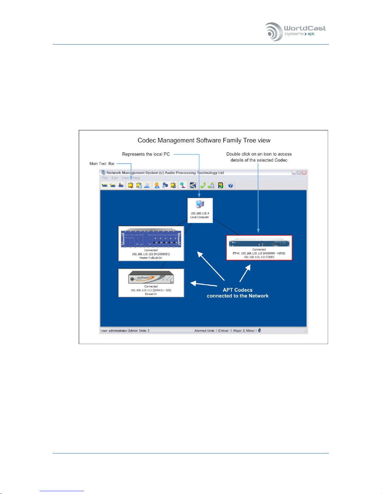
1.7 The WorldCast Codec Management System - Overview
The WorldCast Network Management System (NMS) allows viewing multiple units from one
control point. The program has an intuitive look and feel that is easy to understand by both
the experienced technician and the casual user.
The graphical user interface provides access to an embedded WEB GUI to the Silver IP
Streamer when accessed from the NMS family tree view. The presentation of the GUI of the
Silver units is the same when opened from the family tree view (NMS) or directly from a
WEB browser.
Figure 1-3: Family Tree of the Network Management System (NMS)
The presentation of the Silver configuration pages is the same whether it is opened from
the family tree view (NMS) or directly from a WEB browser.
The NextGen codec range provides a context menu by right-clicking on the device (once
it is connected). This context menu provides an option called “Open Free View” – this
option opens as many independent views of the GUI as required but only one instance in
read-write mode. All other instances are locked to read-only mode.

Silver Stream-In / Stream-Out - System Release 1.5.2 – April 2015
Page 16
Whiterock Business Park - 729 Springfield Road - Belfast BT12 7FP - Northern Ireland
Tel.: +44 28 9067 7200 | Fax: +44 28 9067 7201 | www.aptcodecs.com | contact@aptcodecs.com
The Codec Management System – (continued)
The Codec Management System is designed to operate as a program under Windows as a
single task. This means that only one instance of the NMS software can be installed on the
same PC.
Nevertheless, it’s possible and allowed to have more than one installation of the NMS in the
network. The NMS software design does not allow a simultaneous access to the same Codec
device from different seats. If one seat has opened a Codec device on the family tree, the
software inhibits any attempt of accessing the same unit from another seat in read/write
mode. The first user gets the read-write control of this particular device, and any other user
will be prompted to be restricted on read-only permissions. This feature avoids configuration
conflicts caused by several seats.
Whenever a user opens a device on the family tree, the NMS sends out a broadcast request/announcement to the network looking for any other user actually configuring this particular unit.
If the network does not allow broadcasting, i.e. in public domain networks like the internet,
this protection becomes ineffective.
Notes:
____________________________________________________________
____________________________________________________________
____________________________________________________________
____________________________________________________________
____________________________________________________________
____________________________________________________________
____________________________________________________________
____________________________________________________________
____________________________________________________________
____________________________________________________________
____________________________________________________________

Silver Stream-In / Stream-Out - System Release 1.5.2 – April 2015
Page 17
Whiterock Business Park - 729 Springfield Road - Belfast BT12 7FP - Northern Ireland
Tel.: +44 28 9067 7200 | Fax: +44 28 9067 7201 | www.aptcodecs.com | contact@aptcodecs.com
1.7.1 Installing the Network Management System
Prior to installing and running the NMS software, please ensure that your service PC meets
the minimum hard- and software requirements:
Microsoft Windows
®
XP, Windows® Vista, Windows® 7/8
30 MB free Hard Disc space
1024 px x 768 px Screen Resolution or better
CD ROM Drive (optional)
Running any NextGen-Codec with the current system release on the NMS software re-
quires the NMS build version #1183 or higher (supplied with the Codec).
The NMS requires IP port 7777 and 7778 to be opened on your network!
The NMS software is generally supplied as a self-extracting application. Run the application
and follow the instructions of the following screens:
First Screen
It shows the NMS build version;
please make sure that you’re installing the correct version, this
example shows #1122.
SR 1.5.2 requires NMS ver-
sion 1183 or higher!
Next Screen
Please choose the folder where you
like to install the NMS application.

Silver Stream-In / Stream-Out - System Release 1.5.2 – April 2015
Page 18
Whiterock Business Park - 729 Springfield Road - Belfast BT12 7FP - Northern Ireland
Tel.: +44 28 9067 7200 | Fax: +44 28 9067 7201 | www.aptcodecs.com | contact@aptcodecs.com
Installing the Codec Management System (continued)
Next Screen
Journalist Panel is available for
Eclipse/Meridian type Codecs
only – do not select it unless
you are also running Eclipse or
Meridian units in your network.
Next Screen
You can create a desktop and/or
a quick launch icon as required.
Final Screen
Now you need to complete the
installation by clicking on “In-
stall”.
Silver Stream-In / Stream-Out - System Release 1.5.2 – April 2015
Page 19
Whiterock Business Park - 729 Springfield Road - Belfast BT12 7FP - Northern Ireland
Tel.: +44 28 9067 7200 | Fax: +44 28 9067 7201 | www.aptcodecs.com | contact@aptcodecs.com
1.7.2 Getting Started
Before you can launch the Management System please ensure the following pre-conditions of
your network settings:
To get started with the NMS application, ensure that the cabling is properly connected
from the Codec to the PC, and that your service PC’s Ethernet cards has an IP address
within the range of 192.168.100.0 to 192.168.100.255. The Silver Stream-In and
Stream-Out are set to an IP address within this range as a factory default – usually
192.168.100.110.
The NMS application will remain inactive until a link is established between the service
PC and an active Codec device.
Release Notes
As of this publication date, system release 1.3.0 is shipped with the Codec device. We recommend that you check the APT website for updates.
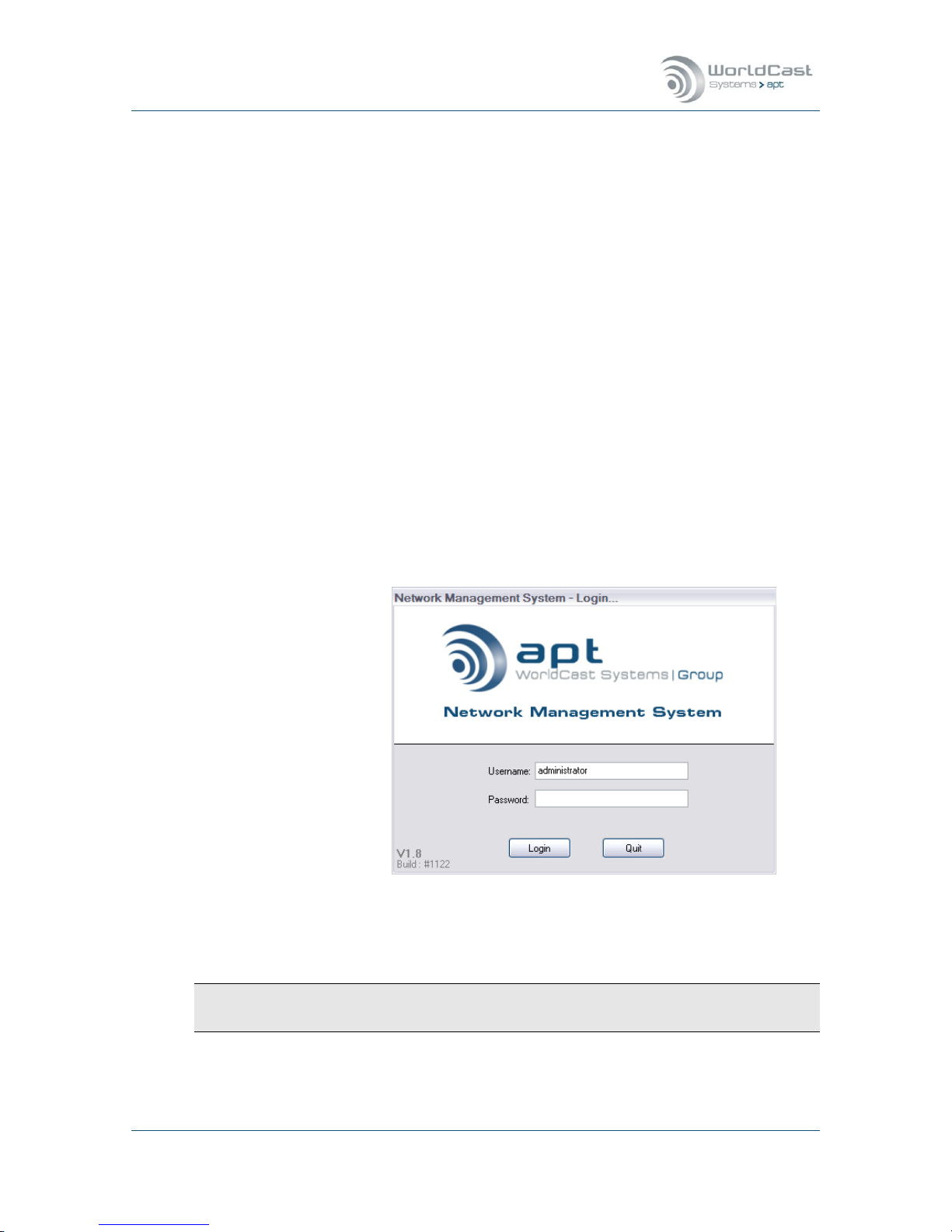
Launch the Management System application. You will find the program located in the Windows Start Menu under “Program WorldNet NMS”. Start the program and you will be
prompted to log in:
NMS Log-In:
There are three levels of
access to the WorldNet
Codec Management System:
All accounts, the “Administrator”, “Normal” and the “Read Only”, require Username and
Password login. When shipped only an Administrator account is configured with the default
login. We recommended that you change the Administrator login as soon as possible.
Default Username: administrator
Default Password: password
Do not forget to change the default password before connecting to an unprotected net-
work!

Silver Stream-In / Stream-Out - System Release 1.5.2 – April 2015
Page 20
Whiterock Business Park - 729 Springfield Road - Belfast BT12 7FP - Northern Ireland
Tel.: +44 28 9067 7200 | Fax: +44 28 9067 7201 | www.aptcodecs.com | contact@aptcodecs.com
Getting started (continued)
Once you have logged in successfully the Main Screen of the Network Management System
(the NMS Family Tree) will appear:
Figure 1-4: The NMS Front Page appears empty, when you log in for the first time
Note: When running the NMS for the first time, this main screen will not show any Codec
devices.
The manual of the WorldCast NMS system is provided with the software. You will find
the full documentation as help file: Click on the menu “Help->Help”

Silver Stream-In / Stream-Out - System Release 1.5.2 – April 2015
Page 21
Whiterock Business Park - 729 Springfield Road - Belfast BT12 7FP - Northern Ireland
Tel.: +44 28 9067 7200 | Fax: +44 28 9067 7201 | www.aptcodecs.com | contact@aptcodecs.com
1.8 IT Security Recommendations
1.8.1 IP Codecs – Network Connection
IP Codecs are network devices! Therefore they should be seen as such. An IP Codec must be
connected to the IP network via a switch or router providing sufficient firewall mechanisms in
order to protect the audio service and the connected network against external attacks. All
network related security rules are valid for an IP Codec as well.
The image below shows the principal of the network connection via the ETH port. The ETH
port must be used for management access and audio streaming. Therefore care must be
taken that the management UDP ports are inaccessible on the streaming network (the external network).
Figure 1-5: This figure shows the recommended network installation: Audio Codec connected to a switch
with firewall mechanism.
It is recommended that the port speed settings on the switch are set to auto negotiate.
Default IP address for LAN: 192.168.100.110 – DHCP disabled on default.

Silver Stream-In / Stream-Out - System Release 1.5.2 – April 2015
Page 22
Whiterock Business Park - 729 Springfield Road - Belfast BT12 7FP - Northern Ireland
Tel.: +44 28 9067 7200 | Fax: +44 28 9067 7201 | www.aptcodecs.com | contact@aptcodecs.com
1.8.2 Management Ports
The following table shows the TCP/UDP ports that should be protected if the Codec is connected to a public network.
Management Ports that should be closed on external connections
TCP 80
WEB Server access
TCP/UDP 111
RPC
UDP 161
SNMP
UDP 162
SNMP TRAP
UDP 2004
Internally used
UDP 5353
MDNS
UDP 5577
Internally used
UDP 7777
APT NMS communication
UDP 7778
APT NMS communication
1.8.3 Default LogIn and Services
Passwords
The Web GUI and the NMS are protected by a user login. The default passwords are trivial password only, like “admin” or “password”. It is obvious, that these passwords are insufficient for a regular use. Furthermore, it is a negligent behavior if this default login
was not changed before connecting to a network. Please refer to section 3.5.2 about how
to change the Web GUI logIn.
Never use the default login for regular operation in an unprotected network!
SNMP
The default names of the community strings must not be used for regular operation. The
default names of community strings, in particular of the Private Community, are widely
used and therefore commonly known. Because SNMPv2c does not support password pro-
tection of the strings, the recommendation is clearly to create the names as “cryptic” as
possible. Refer to section 3.5.7.1 about how to change the community string name.
The names of the SNMP community strings must be changed even if SNMP is not used!
FTP Account
The AoIP card provides an FTP account that is disabled on default. There is no risk from
this service as long as it is kept disabled. FTP service is only used by the ScriptEasy option when a new script is loaded to the unit. FTP must be switched off for normal operation because of security considerations. After a system reboot, the FTP is disabled on default. The FTP login cannot be managed by the user (system immanent). Also refer to
section 3.5.5 about how to control the FTP service.
Make sure that FTP is disabled before connecting the Codec to an unprotected network!

Silver Stream-In / Stream-Out - System Release 1.5.2 – April 2015
Page 23
Whiterock Business Park - 729 Springfield Road - Belfast BT12 7FP - Northern Ireland
Tel.: +44 28 9067 7200 | Fax: +44 28 9067 7201 | www.aptcodecs.com | contact@aptcodecs.com
Installation and Wiring 2.0
This chapter describes the general installation procedure and the wiring of the Silver unit’s
rear panel connectors. This section consists of two parts:
Preparing for installation of the Silver Stream-In/Stream-Out
Wiring power and signal connectors
2.1 Pre-Installation Notes
Always pre-test the system on the bench in its intended configuration prior to installation at
a remote site.
Avoid cable interconnection length in excess of 1 meter (3.3 feet) in strong RF environments
(i.e. on transmitter sites).
2.1.1 Tools and Cables Required
In addition to the content of the packing list, the following items are necessary to complete
the installation.
Network/Management connection cables
One CAT5 Ethernet cable to connect the Silver to a switch.
One CAT5 Ethernet cable to connect the PC to the switch
One CAT5 Ethernet cable to connect the switch to the network
Ethernet hub or switch:
Providing an Ethernet switch facilitate the audio IP link and the management connection
simultaneously (refer to Error! Reference source not found.)
Cables for each payload channel:
At least one standard audio cable equipped with RCA or XLR connectors (depends on the
version of Silver unit)
Power Adapter:
AC power adapter as supplied with the Silver unit

Silver Stream-In / Stream-Out - System Release 1.5.2 – April 2015
Page 24
Whiterock Business Park - 729 Springfield Road - Belfast BT12 7FP - Northern Ireland
Tel.: +44 28 9067 7200 | Fax: +44 28 9067 7201 | www.aptcodecs.com | contact@aptcodecs.com
2.1.2 Front panel Components
Figure 2-1: Silver Stream-In/Stream-Out front panel components
2.1.2.1 Monitoring
(1) The 6.3mm jack socket is provided for audio monitoring with a headset or active monitor
speaker. Depending on the type of Silver unit it is either the audio input (Stream-In) or the
audio output (Stream-Out). This monitor output has a fixed signal level and is not adjustable.
2.1.2.2 Power- Connection - and Alarm Status
(2) The blue Power indicator LED indicates that power is applied to the unit
The red Alarm indicator LED indicates that an alarm condition exists. There are a number of
alarm conditions which can be enabled on the Silver range.
The “Connected” LED shows the presence of a connection. The following table shows the different states of the LED.
Connected LED Color:
Off/Grey
Green
Red
No Stream enabled
X
Receiving & Transmitting ok
X
Connection Error
X
2.1.2.3 Reset Switch – Default IP Addresses
(2) Between the “Connected” and the “Power” LED there is a small hole in the front panel.
Behind this hole sits the IP Address Reset Switch. To change the IP Address of the Silver
units to the default addresses, insert a small tool until and press the switch. Hold it in place
until the Connected LEDs start to flash (about 5 seconds) – then remove it.
The unit will then have changed IP address; it does not need to reboot. It will take a short
while (~10sec) until the Web GUI will be accessible again on the default addresses.
The default IP address of the ETH is: 192.168.100.110

Silver Stream-In / Stream-Out - System Release 1.5.2 – April 2015
Page 25
Whiterock Business Park - 729 Springfield Road - Belfast BT12 7FP - Northern Ireland
Tel.: +44 28 9067 7200 | Fax: +44 28 9067 7201 | www.aptcodecs.com | contact@aptcodecs.com
2.2 Wiring Information
Stream-In/XLR
Figure 2-2: Silver Stream-In rear panel components
Stream-Out/XLR
Figure 2-3: Silver Stream-Out rear panel components
2.2.1 Power Adaptor – DC In
The Silver units are supplied with an external Mains power adaptor suitable to work between
100 VAC and 240 VAC. This power adaptor applies 12 VDC to the unit and has a self-locking
connector.
Do not use another type of AC adaptor than supplied with the unit
2.2.2 Ethernet Interface
This is a 10/100BaseT Ethernet connection with Auto MDI/MDI-X capability on a RJ45 connector.

Silver Stream-In / Stream-Out - System Release 1.5.2 – April 2015
Page 26
Whiterock Business Park - 729 Springfield Road - Belfast BT12 7FP - Northern Ireland
Tel.: +44 28 9067 7200 | Fax: +44 28 9067 7201 | www.aptcodecs.com | contact@aptcodecs.com
2.2.3 Audio Inputs and Outputs on XLR version
The audio inputs on the XLR version accept up to +24 dBu (clip level)
The audio outputs on the XLR version deliver up to +24 dBu (clip level)
Standard XLR-3 female
socket
Audio Input (analog)
Pin
Description
1
screen
2
hot (+ve)
3
cold (-ve)
Analog input levels can be adjusted via the Web GUI in increments of 0.1 dBu. The input impedance is selectable between 600 and >10 k via the Web GUI.
Standard XLR-3 male
socket
Audio Output (analog)
Pin
Description
1
Screen
2
hot (+ve)
3
cold (-ve)
Analog output levels via the Web GUI in increments of 0.1
dBu. The output impedance is selectable between 600 and
50 via the Web GUI.
2.2.4 Audio Inputs and Outputs on RCA version
The audio inputs on the RCA version accept up to +10 dBu (clip level). The input clip level
(internally referenced to digital full scale) can be adjusted in increments of 0.1 dBu from
0 dBu to +10 dBu.
The audio outputs on the RCA version deliver up to +10 dBu (clip level). The output clip level
(internally referenced to digital full scale) can be adjusted in increments of 0.1 dBu from
0 dBu to +10 dBu.

Silver Stream-In / Stream-Out - System Release 1.5.2 – April 2015
Page 27
Whiterock Business Park - 729 Springfield Road - Belfast BT12 7FP - Northern Ireland
Tel.: +44 28 9067 7200 | Fax: +44 28 9067 7201 | www.aptcodecs.com | contact@aptcodecs.com
2.2.5 Auxiliary Data Interface
9 pin female connector
contact view
This is a SELV connection
and must only be con-
nected to other SELV
ports.
RS-232 (DTE) Serial Inputs
Pin
Signal
Description
1
N-C
N.C.
2
Rx
RS-232 Receive
3
Tx
RS-232 Transmit
4
DTR
N.C.
5
GND
Ground
6
N-C
N.C.
7
N-C
N.C
8
N-C
N.C.
9
N-C
N.C
The RS232 auxiliary data channel of the Silver units offer
continuous data transfer rates from 1.200 to 115.200 Baud
(non-embedded on AUX IP-Streams).
An AUX DATA connection on the Silver units can be con-
figured for duplex operation (even that the audio is always simplex).
2.2.6 Ethernet Interface
10BaseT socket
wiring scheme
Ethernet Interface
Pin
Signal
Description
1
Tx +
transmit data +ve
2
Tx -
transmit data -ve
3
Rx -
receive data -ve
4
N-C
Not connected
5
N-C
Not connected
6
Rx +
Receive data +ve
This Ethernet interface is available for both connecting to a
PC running the WorldCast NMS (or WEB browser) and for
sending and receiving audio data.
This ETH port is auto MDI/X enabled. An Auto-MDI/X port
detects if the connection would require a crossover link, and
automatically chooses the MDI or MDIX configuration to
match the other end of the link properly.

Silver Stream-In / Stream-Out - System Release 1.5.2 – April 2015
Page 28
Whiterock Business Park - 729 Springfield Road - Belfast BT12 7FP - Northern Ireland
Tel.: +44 28 9067 7200 | Fax: +44 28 9067 7201 | www.aptcodecs.com | contact@aptcodecs.com
WorldCast/Silver WEB-Browser GUI 3.0
The WorldCast/Silver Web GUI is the control and monitoring tool which communicates with
the Silver units. All the next generation units, including the Silver range, run their own Webserver with can connect to standard Web Browsers or to the APT NMS. It is used to configure
the unit, create audio streams and to get status and alarm information.
This section outlines this application and provides a detailed description of all aspects of the
Silver configuration options.
3.1 The WorldCast WEB GUI - Overview
The Silver Web GUI allows you to view and control a single instance of the Silver IPStreamer. The application has an intuitive look and feel that is easy to understand by both
the experienced technician and the casual user. All configuration instructions described in
this section relate to the WEB GUI. This section provides detailed step-by-step instructions
on how to set up the Silver Stream-In/Stream-Out.
3.1.1 WEB GUI – Technical Requirements
The Web GUI can be run from a standard web browser such as:
1. Mozilla Firefox
2. Google Chrome
3. Safari
4. Internet Explorer v9 and higher
Recommended screen/window size: min. 1280px by 1024px
The GUI is based on a web application using inherent browser technologies only: Java Script,
Cookies and CSS (2.0). The application does not require installing any additional browser
Add-On. The Cookies are session Cookies and used as temporary memory for configuration
changes until they are uploaded to the hardware. A session Cookie expires after the actual
session was closed.
3.1.1.1 Browser Cache
The browser cache is used to hold mainly static parts of the web pages in the PC memory.
However, there are situations where the browser cache cannot be updated correctly and a
manual page refresh will be necessary (reload, ignoring cache).
After the following actions we recommend to re-fresh the web page manually:
1. After firmware update.
2. If any kind of page error appears (corrupted appearance).
3. If an IP address is reused for a Codec which was assigned to another Codec device
previously.

Silver Stream-In / Stream-Out - System Release 1.5.2 – April 2015
Page 29
Whiterock Business Park - 729 Springfield Road - Belfast BT12 7FP - Northern Ireland
Tel.: +44 28 9067 7200 | Fax: +44 28 9067 7201 | www.aptcodecs.com | contact@aptcodecs.com
3.1.2 WEB GUI - Default Network Settings
The Silver units provide a single IP interface for IP audio streaming and web browser control.
The default settings for accessing the web server are (port #80):
ETH
IP Address
Netmask
Gateway
192.168.100.110
255.255.255.0
192.168.100.1
3.2 WEB GUI - Getting Started
Open the preferred web browser and type in the IP address of the Codec you like to configure, and you will be prompted with the LogIn screen.
Figure 3-1: The WEB GUI LogIn screen
The entry field “Screen Name” has been added on system release 1.1.0. The entry of this
field appears as current user name on the inter-communication chat box.
Activating the tick box “Remember me” allows the browser to remember your last user name
for a new session.
3.2.1 WEB GUI - Default LogIn
By default the Administrator account is selected. The user management allows modifying this
account and it also allows setup a read-only account.
Default LogIn, User: Admin - Password: admin
A security alert will pop up as long as the default login has not been changed. This alert can
be remedied only by changing the login.
We strongly recommend changing the Default Account before commissioning!
Silver Stream-In / Stream-Out - System Release 1.5.2 – April 2015
Page 30
Whiterock Business Park - 729 Springfield Road - Belfast BT12 7FP - Northern Ireland
Tel.: +44 28 9067 7200 | Fax: +44 28 9067 7201 | www.aptcodecs.com | contact@aptcodecs.com
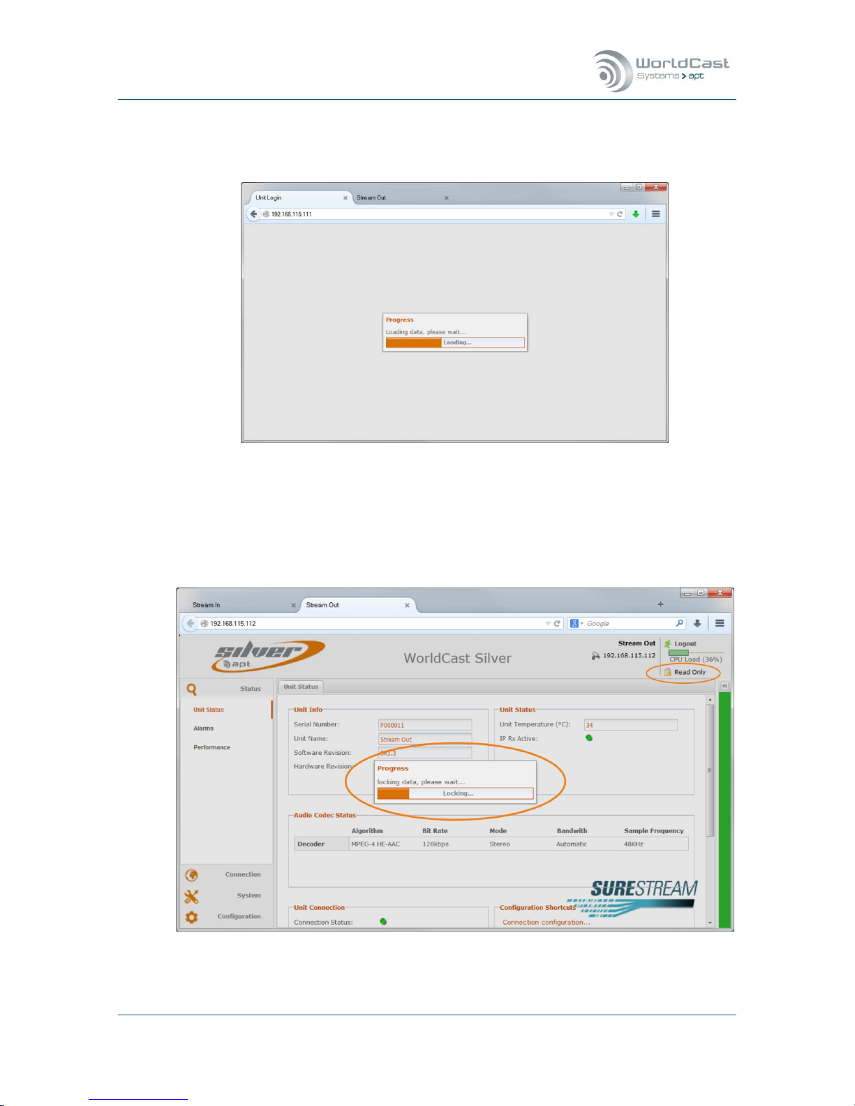
3.2.2 Loading and Locking
After you have submitted correctly the web browser starts loading the web application.
Figure 3-2: Loading the application data from the unit
For a full read/write access the GUI must lock the current session. Read/write is an exclusive
status and is applied to the first user who logs in. Any other user who tries to log in after will
be set to a read-only status. The read-only status is shown on the top right corner of the
window.
Figure 3-3: After loading the status page the GUI tries to lock the current session for read/write access
Silver Stream-In / Stream-Out - System Release 1.5.2 – April 2015
Page 31
Whiterock Business Park - 729 Springfield Road - Belfast BT12 7FP - Northern Ireland
Tel.: +44 28 9067 7200 | Fax: +44 28 9067 7201 | www.aptcodecs.com | contact@aptcodecs.com
3.2.3 Additional Status Indications
3.2.3.1 Activated Licenses
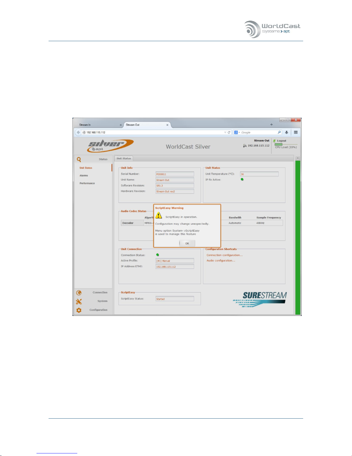
In dependence of already applied option licenses the unit may show additional warnings during loading the control interface. The image below shows a unit with the ScriptEasy license
enabled. If ScriptEasy is enabled the currently loaded control script will be activated during
start-up. An alert window indicates this status and asks the user to acknowledge. Clicking on
the “OK” button enables the normal access to the control interface.
Figure 3-4: Shows the ScriptEasy alert window during start-up
Note: Whenever a ScriptEasy script is loaded, this script is automatically active after
booting the unit! More information about the use of ScriptEasy is provided in section
3.5.8.1.
3.2.3.2 CPU Utilization
With this release a CPU utilization bar is added on the top right corner of the Main Page. This
indication provides information about the CPU load in real-time. In dependence of the number of IP streams and the selected audio algorithm the CPU load can vary significantly.
It is important not to overload the CPU!

Silver Stream-In / Stream-Out - System Release 1.5.2 – April 2015
Page 32
Whiterock Business Park - 729 Springfield Road - Belfast BT12 7FP - Northern Ireland
Tel.: +44 28 9067 7200 | Fax: +44 28 9067 7201 | www.aptcodecs.com | contact@aptcodecs.com
3.2.4 Status Page
Once the Web GUI has downloaded the application data from the Codec it will show the Status Page of the WEB application. The Status Page consists of three sections: The main menu
(1) on the left hand side, the main pages (2) in the middle and the “Current Status” frame
(3) on the right hand side which can be hidden and indicated by a colored bar (green, yellow
or red in dependence of current alarm events).
Figure 3-5: Shows the Unit Status page of a Stream-In unit with popped up "Current Status" frame
The default Main Page (2) is always the Unit Status page summarizing the status of the
hardware unit, the current Audio Codec settings and the Connection Status. The color of the
stylized LEDs indicates the current status condition (either green or red).
3.2.5 Session Close/Session Time Out
Each time the browser connects to the hardware in read/write mode (Admin account) a new
session will be opened. This session must be closed after a period of time in order to allow
another seat connecting to the Codec in read/write mode. A timer ensures that a session
cannot keep open accidently and closes the session after 70 minutes automatically, if no action takes place in this period of time. A session can be closed manually by using the “Logout” button, closing the browser or the browser tab or by forcing a reloading of the application data by pressing the F5 key
.

Silver Stream-In / Stream-Out - System Release 1.5.2 – April 2015
Page 33
Whiterock Business Park - 729 Springfield Road - Belfast BT12 7FP - Northern Ireland
Tel.: +44 28 9067 7200 | Fax: +44 28 9067 7201 | www.aptcodecs.com | contact@aptcodecs.com
3.2.6 Main Menu
The main menu is always present on the left hand side of the browser window. In dependence of the selected menu item it will expand and show related submenu items.
Figure 3-6: The Main Menu expands in dependence of the selected menu item. The “Current Status”
frame is hidden and actually indicated by the green bar on the right hand side (“good” condition).
The screen shot above shows the expanded main menu (1) with related sub menu entries of
the current main page. This figure also displays the hidden “Current Status” frame. This
frame is indicated by the currently green color (good condition). Clicking on this colored bar
pops up this frame.
A selected menu entry opens the corresponding page and the tool bar (4) on the bottom of
the browser window which provides related toolbar items
The “Current Status” bar changes its color in dependence of the current conditions. Pos-
sible colors are: GREEN (no error), ORANGE (minor error), RED (major error) and light
BLUE (no active configuration).

Silver Stream-In / Stream-Out - System Release 1.5.2 – April 2015
Page 34
Whiterock Business Park - 729 Springfield Road - Belfast BT12 7FP - Northern Ireland
Tel.: +44 28 9067 7200 | Fax: +44 28 9067 7201 | www.aptcodecs.com | contact@aptcodecs.com
3.3 Main Menu - Status
Starting the WEB application will always open the Main Menu “Unit Status” item with the Unit
Status page and the corresponding sub menu items loaded. The Unit Status page is organized in various sections.
Figure 3-7: Main Menu Status - Unit Status page
Browser Main Frame
The Browser window shows on the top right corner the IP address and the unit name
(“Stream Out”) which was applied to the unit (refer to sec. 3.5.12); it also provides information if the browser is connected in Read-Only Mode and presents the link for logging out from the unit.
Unit Info Section
This section displays the hardware and release version:
1. Serial Number
2. Unit Name (name can be entered on the “About” screen)
3. Firmware Revision
4. Hardware Revision

Silver Stream-In / Stream-Out - System Release 1.5.2 – April 2015
Page 35
Whiterock Business Park - 729 Springfield Road - Belfast BT12 7FP - Northern Ireland
Tel.: +44 28 9067 7200 | Fax: +44 28 9067 7201 | www.aptcodecs.com | contact@aptcodecs.com
Unit Status (continued)
Unit Status Section
1. Unit Temperature
This shows the current Engine temperature of the unit and is not the environmental temperature. This value can exceed 40°C without causing a critical situation. There are no
fans fitted as default for two reasons; the emitted noise, and fans are wear and tear
items which need to be replaced periodically.
2. IP Transport Error
This error indication is related to IP data stream. If a stream is enabled on the streams
table it broadcasts any IP error to this alarm indication.
Audio Codec Status
This section provides information about the currently active Codec settings for the Encoder (Stream-In) or the Decoder (Stream-Out).
Unit Connection
This section shows the currently active connection, i.e. the status, the name of the loaded profile and the unit’s IP address. The stylized LED indicates a physical “Loss of Con-
nection” on the IP interfaces if a stream is assigned to the interface (this is a copy of the
“Current Status” frame item).
Configuration Shortcut
This section provides direct links to:
1. Connection Configuration page (advanced configuration)
2. Audio Configuration Page
Optional Information
In dependence of applied options licenses this page also shows status information about
these options, e.g. for SureStream the SureStream logo, for ScriptEasy the current activity status, etc. SureStream is a standard feature and should appear all the time.
ScriptEasy activity status
3. “Unlicensed” – either no ScriptEasy license was applied OR no script was loaded
4. “Started” – Script loaded and active (running)
5. “Stopped” – Script loaded but temporarily stopped
Notes:
____________________________________________________________
____________________________________________________________
____________________________________________________________

Silver Stream-In / Stream-Out - System Release 1.5.2 – April 2015
Page 36
Whiterock Business Park - 729 Springfield Road - Belfast BT12 7FP - Northern Ireland
Tel.: +44 28 9067 7200 | Fax: +44 28 9067 7201 | www.aptcodecs.com | contact@aptcodecs.com
3.3.1 Current Status Frame
This “Current Status” frame allows a quick inspection of the current condition of a running
configuration. Clicking on the little arrows on top of the bar opens it as browser frame. In
this mode it is re-sizable and parameters can be changed (e.g. refreshment cycles). Clicking
on the colored bar opens this window as popup window with a fixed size and in read-only
mode.
Figure 3-8: Two methods to open the "Current Status" frame; re-sizable or in read-only mode.
The “Current Status” bar changes its color in dependence of the current conditions. Pos-
sible colors are: GREEN (no error), ORANGE (minor error), RED (major error) and BLUE
(no active configuration)
Date and Time (5)
Indicates the current system date and time. Date and
time settings are located in the “System” menu
Unit Connection (6)
The stylized LED indicates the IP connection status of
either of activated IP interfaces, i.e. if a stream is assigned to the interface.
Audio Levels (7)
These level bars are representing always the digital
signal domain reading as dBFS. The analog levels can
be adjusted on inputs and outputs defining the equivalence from the digital clip level of 0 dBFS. The refresh
period can be set from 500 milliseconds to 10 seconds.
Alarms (8)
This window shows current system or connection
alarms in real time. It indicated the level of severity
by LED colors (red and orange), the alarm name and
the alarm description.
Figure 3-9: Current Status frame on a
Stream-In unit

Silver Stream-In / Stream-Out - System Release 1.5.2 – April 2015
Page 37
Whiterock Business Park - 729 Springfield Road - Belfast BT12 7FP - Northern Ireland
Tel.: +44 28 9067 7200 | Fax: +44 28 9067 7201 | www.aptcodecs.com | contact@aptcodecs.com
3.3.2 Alarm Status
The following screen will appear, showing the alarm status. Note that a Red stylized LED
means the alarm has been raised. Green means everything is working normally and Grey
means this alarm is not enabled or not applicable.
Figure 3-10: Main Menu Status – Alarms page from a Stream Out (Decoder)
Note that any of the Transmit or Input Silence Detection alarms will not appear for the
Stream-Out Silver Product.
Audio Alarms Section
This section shows the status of the audio alarms. The alarms indicated in this section
are Silence Detection Alarms for Left and Right Input (A/B on Stream-In) or Output (C/D
on Stream-Out) and Sync alarm (on Stream-Out only).
1. Audio Alarms (Silence Detection)
The Audio signal has decreased below the threshold and timeout specified in the audio
configuration menu. This alarm will be flagged if silence occurs on the inputs (Stream-In)
or on the outputs (Stream-Out) for any reason.

Silver Stream-In / Stream-Out - System Release 1.5.2 – April 2015
Page 38
Whiterock Business Park - 729 Springfield Road - Belfast BT12 7FP - Northern Ireland
Tel.: +44 28 9067 7200 | Fax: +44 28 9067 7201 | www.aptcodecs.com | contact@aptcodecs.com
Alarms Page (continued)
2. Sync Failure (AutoSync Alarm) – Stream-Out only
This Alarm indicates a general sync failure in situation where an excessive amount of
packets were dropped or out-of-sequence that results in a gap to the audio stream significant enough to generate the Sync alarm. The different audio algorithms or linear PCM
have their specific sync-failure sensitivity.
For Enhanced apt-X this alarm corresponds to the AutoSync Alarm. AutoSync is a bit pattern sent embedded in the Enhanced apt-X audio stream that allows a very rapid resumption of decoding after a gap in the bit stream. This alarm will be flagged if the following conditions occur (for network faults, usually along with other network specific
alarms too):
- Mismatch of audio algorithms on Transmit and Receive units
- Connection or transport errors
- A Call being dropped by the Transmit unit
Dynamic DNS Alarm
This alarm indicates the loss of connection to the Dynamic DNS service. The Dynamic
DNS service configuration is located on the Network/DynDNS configuration page (system
menu).
Transport Alarms
This section covers IP alarms only such as IP Rx or Tx errors and audio mismatch.
1. IP Tx Error – Stream-In
The packets from the Tx unit have not been confirmed as hitting the Rx unit – either the
Rx unit is stating in its RTCP stream that there has been no packets, the RTCP port has
been blocked, or there is another form of network fault resulting in no line of sight to the
Rx codec.
2. IP Rx Error – Stream-Out
Packets are not arriving to the Decoder, and it is expecting to see traffic. This can be
caused by stream being dropped on the Encoder, a network fault or mismatch in audio
algorithm settings.
3. Audio Mismatch
This is likely to be raised if the algorithm and packet size do not match on both sides of
the link.
Loss of physical Connection (ETH)
Physical loss of connection to network directly (lead pulled)

Silver Stream-In / Stream-Out - System Release 1.5.2 – April 2015
Page 39
Whiterock Business Park - 729 Springfield Road - Belfast BT12 7FP - Northern Ireland
Tel.: +44 28 9067 7200 | Fax: +44 28 9067 7201 | www.aptcodecs.com | contact@aptcodecs.com
3.3.3 Performance Monitor
The Performance Monitor is for all active transmit or receive streams. Clicking on an individual stream in the Stream Performance Table will display the performance details below the
table. The time interval for the data update is set to 1 second as default, but it is user selectable down to 500 ms and up to 10 seconds. The Buffer Level Display is the graphical
equivalence of the current receive buffer condition (shown on receive routes only).
Clicking on the “Reset” button resets the IP statistics. A shortcut allows the direct navigation
to the stream configuration page “Connection Configuration”.
Figure 3-11: Main Menu Status - Performance Monitor page on the Decoder (Stream-Out)
Stream Table (1)
The Stream Table shows all active and inactive streams. On a Decoder (Stream-Out) it is always a single audio stream and a single AUX Data stream, while on the Encoder (Stream-In)
many streams can be shown on this table.
Rx or Tx IP Statistics (2)
This section displays the dynamic IP stream parameter as well as the static information like
the Source IP address and the Source IP port (on Stream-Out only).
Buffer Level (3)
This colored scale represents the actual de-jitter buffer status. This scale shows in intervals
the actual buffer level (on Stream-Out only).

Silver Stream-In / Stream-Out - System Release 1.5.2 – April 2015
Page 40
Whiterock Business Park - 729 Springfield Road - Belfast BT12 7FP - Northern Ireland
Tel.: +44 28 9067 7200 | Fax: +44 28 9067 7201 | www.aptcodecs.com | contact@aptcodecs.com
3.3.3.1 IP Statistics – Details
This section shows the IP statistics (2) & (3) on figure 3-11 of a selected stream when an active connection is in progress, the table below provides the description of each of the statistics (for Encoder or Decoder).
Statistic
Description
Stream Name
Shows the name of the analyzed stream
Rx or Tx Packet Interval
Shows the packet time (p-time in msec.) and the packet rate
per second
Rx or Tx Packet Size
Size of received or transmitted packet in Bytes
Rx or Tx kB Count
Kilo Bytes received or transmitted
Rx or Tx Bit Rate
Bit rate of receive or transmit stream (data & IP overhead)
Rx or Tx Packet Count
Number of packets received or transmitted
Rx Source IP Address
IP Address of the transmitting Codec
Rx Source IP Port
IP Port on which the transmitting Codec is sending the stream
Rx Dropped Packets
Count
Number of dropped packets
Rx Duplicated Packets
Count
Number of duplicated packets arrived on the Rx stream.
Rx Re-Sequenced
Packets Count
Number of packets that reached the de-jitter buffer out of sequence (indicates also the level of re-sequencer activities)
Rx Flooded Buffer
Count
The Buffer has detected above 180%. Buffer level has been
normalized to mid-point by the engine
Loss of Connection
Loss of connection, the buffer has dropped to less than 10% and
the receiver has reset the buffer
Statistic records can be reset by clicking on the “Reset” button (refer to Figure 3-11:
Main Menu Status - Performance Monitor page on the Decoder (Stream-Out)
3.3.3.2 IP Statistics – Receive Buffer Level
This Buffer Level display is the graphical equivalence of the current receive buffer condition
(shown on receive routes only). This example
shows a buffer which is set to 150 ms nominal.
In dependency on the delay jitter behavior of the
network the actual level marker will swing
around the nominal value. As long as the maker
stays in the green area the buffer management
can cope with this amount of deflection.
A high value of deflection indicates that the nominal buffer level is set too low. Increasing the
value keeps the marker closer to the mid-point.
A high deflection of the level marker indicates that the nominal buffer level may be too
low. Increasing the nominal level reduces these deflections.

Silver Stream-In / Stream-Out - System Release 1.5.2 – April 2015
Page 41
Whiterock Business Park - 729 Springfield Road - Belfast BT12 7FP - Northern Ireland
Tel.: +44 28 9067 7200 | Fax: +44 28 9067 7201 | www.aptcodecs.com | contact@aptcodecs.com
3.3.3.3 About Stream Tables (general)
In general, a Stream Table (1) is a list of IP-Stream configurations organized in a table. In
dependence on where a stream table is accessed it will appear as read-only table, like on the
performance monitor page, or the table can be directly accessed for changing values and entries.
Figure 3-12: Shows Stream Tables from the Encoder and the Decoder
Streams Table Exposure Options
The exposure options of the Stream Table are flexible and can be widely controlled by the
user. Clicking on the little arrow on each of the columns (on mouse over) opens a context
menu and allows sorting the table ascending or descending. Another submenu provides tick
boxes for controlling the columns visibility. In general the stream table exposure also depends on the size of the current browser window. The width of the columns can be adjusted
by clicking between the columns and drag the border as appropriated.
Figure 3-13: Exposure options on the Streams Table
Silver Stream-In / Stream-Out - System Release 1.5.2 – April 2015
Page 42
Whiterock Business Park - 729 Springfield Road - Belfast BT12 7FP - Northern Ireland
Tel.: +44 28 9067 7200 | Fax: +44 28 9067 7201 | www.aptcodecs.com | contact@aptcodecs.com
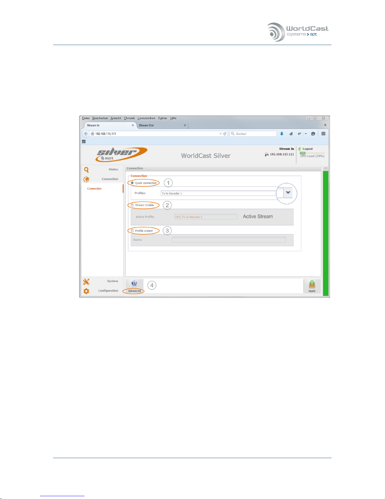
3.4 Main Menu – Connection
The connection page is the page where Connection Profiles can be created and IP streams
can be enabled or disabled. This page also provides a Profile Wizard for a step-by-step procedure.
A connection profile is a set of configuration parameters related to IP connections. A profile
stores audio Codec settings and IP stream configurations
Figure 3-14: Shows the Connection Page of the Stream-In unit
The WEB GUI offers four ways to create, manage and to apply a Configuration Profile:
1. Quick Connection - loads an existing profile (1)
2. Stream Enable – allows enabling and disabling of streams of the current profile (2)
3. Profile Wizard – provides a step-by-step procedure (3)
4. Advanced Configuration - manual stream configuration procedure (4)
Note: All changes made on the WEB GUI can be reverted and will not become active un-
til it was applied to the Codec hardware!
Silver Stream-In / Stream-Out - System Release 1.5.2 – April 2015
Page 43
Whiterock Business Park - 729 Springfield Road - Belfast BT12 7FP - Northern Ireland
Tel.: +44 28 9067 7200 | Fax: +44 28 9067 7201 | www.aptcodecs.com | contact@aptcodecs.com
Connection Page (continued)
Quick Connection (1)
A “Quick Connection” is basically a pre-configured and previously stored profile. This profile was created and merged from an audio mode configuration and an IP stream setup.
Before a Quick Connection can be used, a profile must have been created first.
Clicking on the little arrow opens a list with available profiles. Once the required profile
was selected it can be applied seamlessly to the Codec by clicking the “Apply” button on
the bottom right corner.
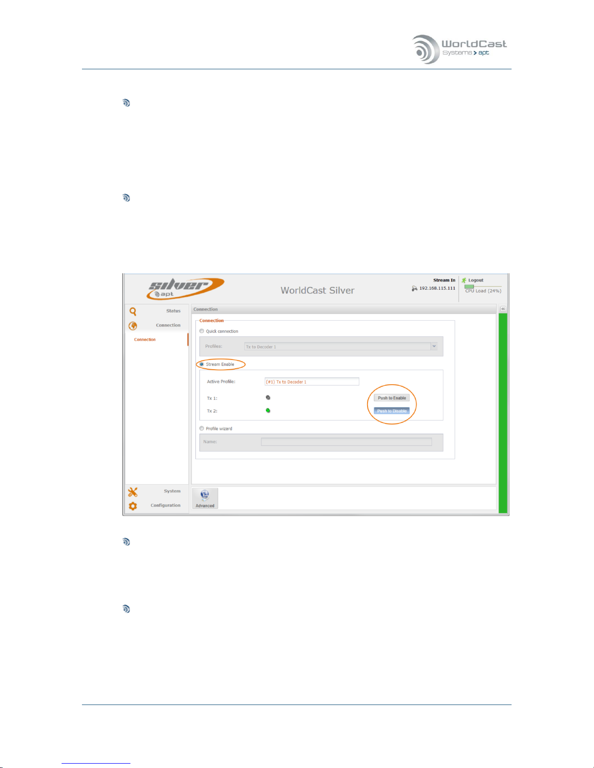
Stream Enable (2)
This section allows enabling or disabling each single stream of a loaded profile. The profile on the screen shot below has two Tx streams. The stream labelled as Tx1 is disabled.
Clicking on the “Push to Enable” button will enable this stream immediately. It is not
necessary to confirm this change. The “Apply” button disappears for this function.
Profile Wizard (3)
The “Configuration Wizard” guides to a step-by-step procedure creating a profile. It
prompts for audio settings and for IP settings. Finally it creates a profile by merging both
components. Once a profile was created it appears on the Quick Connection drop down
list.
Advanced Configuration (4)
The “Advanced” configuration procedure provides all configuration and management options on a single page. Other than the Configuration Wizard the “Advanced” configuration
allows modifications on the currently applied profile and configuration. It also provides
options and tools to edit already created profiles.

Silver Stream-In / Stream-Out - System Release 1.5.2 – April 2015
Page 44
Whiterock Business Park - 729 Springfield Road - Belfast BT12 7FP - Northern Ireland
Tel.: +44 28 9067 7200 | Fax: +44 28 9067 7201 | www.aptcodecs.com | contact@aptcodecs.com
3.4.1 Profile Wizard - Creating a Profile
Profile Wizard – Profile Name
Selecting the radio box “Connection Wizard” on the connection page starts the Wizard. Firstly
a profile name must be entered in the Name field. Once a name is entered the “Next” button
becomes active. Clicking on this button opens the next page prompting the audio Codec settings.
Figure 3-15: Shows the Connection Wizard's first page
Notes:
____________________________________________________________
____________________________________________________________
____________________________________________________________
____________________________________________________________
____________________________________________________________
____________________________________________________________
____________________________________________________________
____________________________________________________________
____________________________________________________________
____________________________________________________________

Silver Stream-In / Stream-Out - System Release 1.5.2 – April 2015
Page 45
Whiterock Business Park - 729 Springfield Road - Belfast BT12 7FP - Northern Ireland
Tel.: +44 28 9067 7200 | Fax: +44 28 9067 7201 | www.aptcodecs.com | contact@aptcodecs.com
3.4.2 Profile Wizard – Encoder Settings
The next page guides to the Audio mode settings. The Silver units provide similar pages for
the Encoder and the Decoder depending on the type of unit, hence the Encoder configuration
is provided on the Stream-In unit and the Decoder configuration on the Stream-Out.
Figure 3-16: Shows the Encoder configuration page (Stream-In)
Algorithm
Clicking on the “Algorithm” field opens the drop down list offering the available audio co-
dec formats.. Select the desired format then click on the “Bit Rate” field.
Bit Rate
Corresponding to the chosen audio format this drop down list presents the available bit
rates. After selecting the bit rate, the “Mode” field entry may be filled automatically in
dependence of the audio mode and chosen bit rate.
Audio Mode
Audio Mode means either Mono or Stereo. If this field is not computed automatically,
chose the desired mode. Finally the “Bandwidth” field displays the resulting audio bandwidth and the sample frequency.
Silver Stream-In / Stream-Out - System Release 1.5.2 – April 2015
Page 46
Whiterock Business Park - 729 Springfield Road - Belfast BT12 7FP - Northern Ireland
Tel.: +44 28 9067 7200 | Fax: +44 28 9067 7201 | www.aptcodecs.com | contact@aptcodecs.com
Codec Settings (continued)
3.4.2.1 Embedded AUX Data (Using Serial Port)
For the majority of audio algorithms (except Liner PCM) auxiliary data can be embedded
into the audio stream. Once a suitable audio algorithm is selected and configured, the
Serial Port drop down list becomes active. The embedded data channel accepts RS232
data up to 9.600Baud. Audio algorithms have baud rate constraints in dependence of the
selected audio bit rate
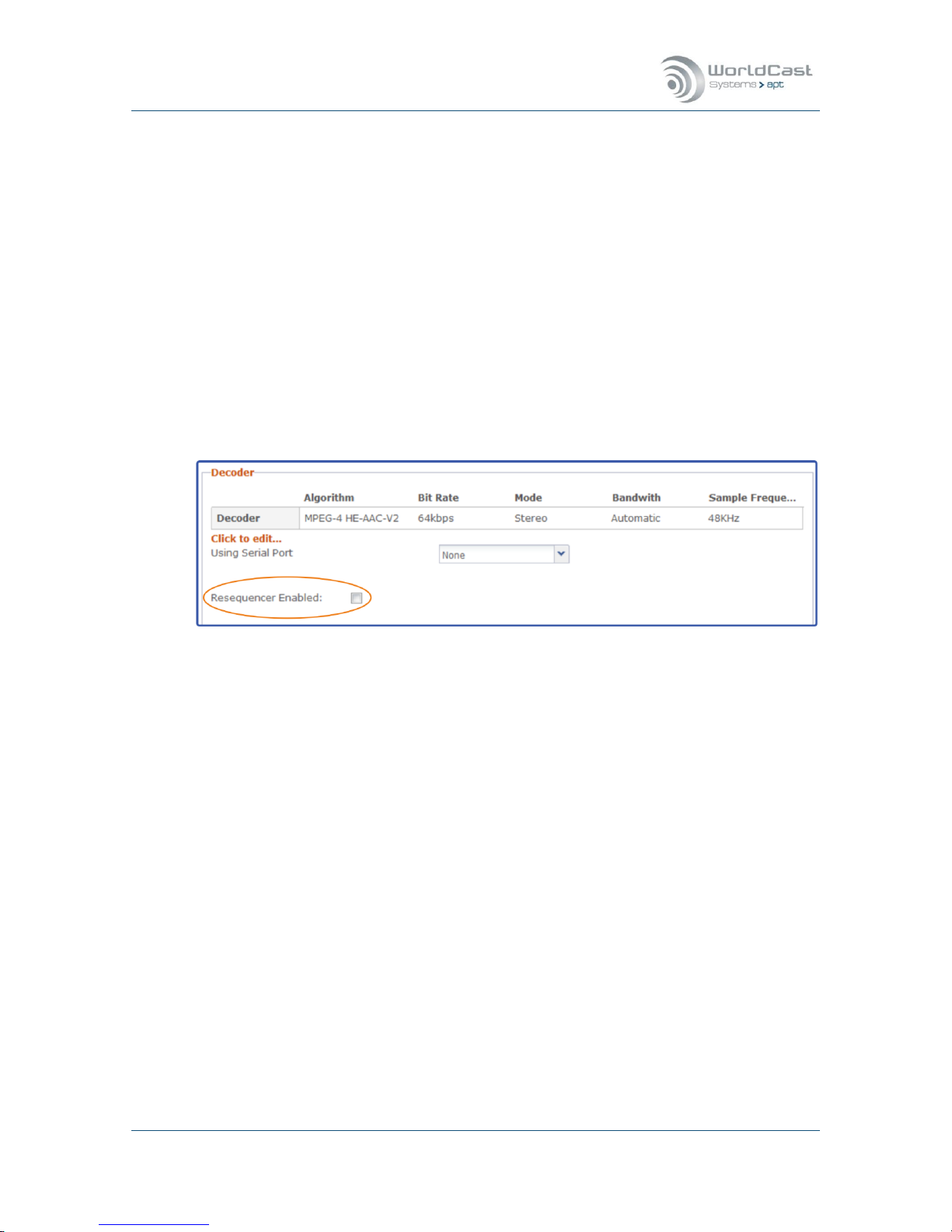
3.4.2.2 Decoder Settings
The principal of the Encoder and Decoder configuration is almost identical. But there is one
important setting option on the Decoder page: The Re-Sequencer check box – keep this enabled! This ensures that packets arriving out of order can be re-ordered inside the de-jitter
buffer.
Decoder Packet Re-Sequencer
The Decoder can utilize the Packet Re-Sequencer to keep arriving packets in the right order
even if they arrive in the wrong sequence because of the network delay jitter behavior. The
Re-Sequencer needs a minimum number of packets in the buffer for performing efficiently.
This value is set to a minimum of six (6) packets and cannot be changed. In consequence
the de-jitter buffer size must be chosen in accordance with the packet size. The validation
engine prompts you to modify this setting whenever a mismatch of packet size and buffer
size is identified (also refer to section 3.4.8).
After completing the Encoder or Decoder settings, click on the “Next” button to enter the IP
Stream configuration page.
For an ultra-low delay application in a managed network (nearly 0 ms delay jitter) the
re-sequencer might be disabled in order to allow a minimum buffer size of three (3) IP
packets

Silver Stream-In / Stream-Out - System Release 1.5.2 – April 2015
Page 47
Whiterock Business Park - 729 Springfield Road - Belfast BT12 7FP - Northern Ireland
Tel.: +44 28 9067 7200 | Fax: +44 28 9067 7201 | www.aptcodecs.com | contact@aptcodecs.com
3.4.3 Connection Wizard – IP Streams Configuration
Reaching this window within the Connection Wizard implies that your Codec settings are
completed. The audio settings can be changed using the “Advanced” configuration option,
but not within the Connection Wizard.
Figure 3-17: Shows the IP Stream configuration page on the Encoder with the stream setup window
Adding a Stream
Clicking on the “Stream Management” button (1) provides all options for creating and ed-
iting IP streams. Clicking on “Add” opens the Stream Configuration window (2). This
Window provides all setting options for the desired IP connection. Once the first stream is
completed a second or more streams can be added by clicking on the “Add” button again.
Each stream gets a unique ID assigned by the system. This ID cannot be modified by users.
As long as the profile is not yet created a stream can be edited by double clicking on the
stream or can be deleted by using the “Remove” function. The “Copy” function allows
copying a selected stream.
If the “Cancel” button is clicked, all configurations will be deleted including the audio
settings and the profile name.

Silver Stream-In / Stream-Out - System Release 1.5.2 – April 2015
Page 48
Whiterock Business Park - 729 Springfield Road - Belfast BT12 7FP - Northern Ireland
Tel.: +44 28 9067 7200 | Fax: +44 28 9067 7201 | www.aptcodecs.com | contact@aptcodecs.com
3.4.4 Profile Wizard – Saving a Profile
After all streams are created they appear on the Streams Table. The little blue marker on the
table fields indicate that the stream was not yet saved in a profile and can be modified.
Finally the streams must be enabled before they can be merged into a profile. The most
left column on the stream table presents the “Enable” checkbox.
Figure 3-18: Shows two streams ready for being merged into a profile
Clicking on the “Create” button (3) now merges the audio settings with the IP stream config-
uration into the new profile. This completes the Connection Wizard and opens the “Ad-
vanced” configuration window.
Notes:
____________________________________________________________
____________________________________________________________
____________________________________________________________
____________________________________________________________
____________________________________________________________
____________________________________________________________
____________________________________________________________

Silver Stream-In / Stream-Out - System Release 1.5.2 – April 2015
Page 49
Whiterock Business Park - 729 Springfield Road - Belfast BT12 7FP - Northern Ireland
Tel.: +44 28 9067 7200 | Fax: +44 28 9067 7201 | www.aptcodecs.com | contact@aptcodecs.com
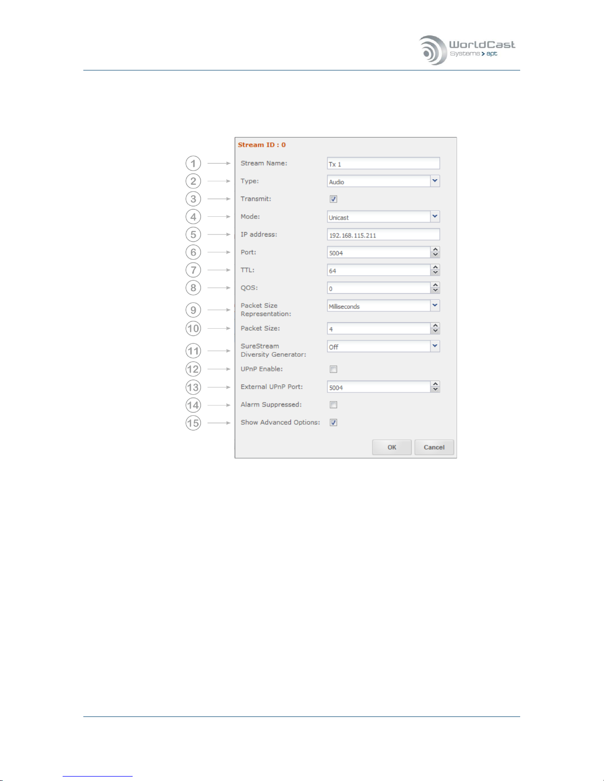
3.4.5 IP Stream Configuration – general
The stream configuration window can provide many options for different stream types and
operational modes. Adding a new stream shows the configuration window with basic options
only. The default values of the advanced configuration window suit for many applications.
However, if these must be inspected or changed the “Show Advanced Options” tick box allows access to all parameters.
Figure 3-19: Shows the basic configuration options for Audio Tx
Figure 3-20: Shows the basic configuration options for Audio Rx
Enabling the “Show Advanced Options” tick box expands the window offering all configuration options. The following sections discuss the complete configuration.
Note: In dependence of the selected stream type, the options provided are different.

Silver Stream-In / Stream-Out - System Release 1.5.2 – April 2015
Page 50
Whiterock Business Park - 729 Springfield Road - Belfast BT12 7FP - Northern Ireland
Tel.: +44 28 9067 7200 | Fax: +44 28 9067 7201 | www.aptcodecs.com | contact@aptcodecs.com
3.4.5.1 About Stream Types
Figure 3-21: Shows the stream type selection menu
Audio Stream
An Audio stream is send via RTP/UPD. The possible streaming mode is:
1. Simplex only, Transmit on Stream-In and Receive on Stream-Out
AUX Data Stream
An AUX data stream is send via UDP datagrams only. This is different from the RTP/UDP
mode and is not treated by the RTP engine at all. In consequence an AUX stream does
not pass the de-jitter buffer on the receiving side. As a result, an AUX data stream is not
synchronized with the audio content – it is always faster than the audio by the amount of
the de-jitter buffer size.
1. Transmit or Receive on both Streamer types
IP Packet Forwarding
The IP packet forwarding mode is data agnostic and can consist of UDP or RTP/UDP payload (in dependence of the received and forwarded stream type).
The possible streaming modes are:
1. Transmit or Receive on both Streamer types
Silver Stream-In / Stream-Out - System Release 1.5.2 – April 2015
Page 51
Whiterock Business Park - 729 Springfield Road - Belfast BT12 7FP - Northern Ireland
Tel.: +44 28 9067 7200 | Fax: +44 28 9067 7201 | www.aptcodecs.com | contact@aptcodecs.com
3.4.6 Audio Stream Configuration
3.4.6.1 Transmit (Tx) Stream-In
Figure 3-22: The IP Stream configuration window showing the available transmit options (Audio)
In dependence of the selected stream type: Audio, AUX or IP Forwarding and the
streaming mode: Transmit, Receive or bidirectional, the available options will change.
Notes:
____________________________________________________________
____________________________________________________________
____________________________________________________________
____________________________________________________________
____________________________________________________________
____________________________________________________________
____________________________________________________________

Silver Stream-In / Stream-Out - System Release 1.5.2 – April 2015
Page 52
Whiterock Business Park - 729 Springfield Road - Belfast BT12 7FP - Northern Ireland
Tel.: +44 28 9067 7200 | Fax: +44 28 9067 7201 | www.aptcodecs.com | contact@aptcodecs.com
Audio Streams Configuration (continued)
1. Name: Enter the name for this stream
2. Type: Select Stream Type: Audio
3. Enable “Transmit”
4. Casting Mode: Unicast is a point-to-point connection. The stream can be sent to one de-
coder only. Multicast allows point-to-multi point streaming and uses the IGMP protocol
for managing multicast joins and leaves.
5. IP-Address: Enter the destination IP address or the hostname of the remote unit.
For unicast: This is the unique IP address of the remote receiver or the gateway.
For unicast: Entering a hostname requires active Dynamic DNS (refer to section 3.5.3.2).
For multicast: Enter the multicast group address.
6. Port: This is the IP port number of the remote Codec (destination IP port). The number
selected here means, that the stream must be received at the remote site on this port
number. Each stream must use a separate port number. UDP/RTP port numbers are defined as even numbers in the 5000 range (5004/5006/5008 and so on); the odd numbers are reserved for the RTCP protocol and should not be used.
7. TTL: Time to live describes the number of network hops the packet can pass. Each
passed hop reduces the TTL number by 1. If the TTL value becomes 0 and has not
reached the destination, it will be deleted. This avoids flooding the network with “blind”
packets.
8. QoS: Quality of Service: If the network supports QoS mechanisms (not the Internet), the
here entered values (DSCP / DiffServ) can be evaluated by the QoS enabled routers. QoS
defines a mechanism for prioritizing this IP stream against other IP traffic in the network.
Note, QoS is a network feature, the Codec allows the QoS tagging of the stream only.
The range is from 0 (off) to 63 (highest priority). It is important to know about the QoS
implementation of the network, before entering a value – not all values will be accepted
by the network router.
9. Packet Size Representation: A packet size can be described in Bytes/Packet or in
Time/Packet (packet time, p-time). The option “Full Frame” is required for all framed algorithms. Framed algorithms are all MPEG formats; these formats define the packet size
in accordance with the algorithm settings. The “Auto” mode configures 4ms packet size
for unframed algorithms (Eapt-X and linear PCM).
10. Packet Size: Packet size describes the size of the payload in the UDP packet. It can be
selected in bytes per packet or time per packet for all non-MPEG algorithms. For MPEG
algorithms, use “Full Frame”. If p-time is the representation mode, the value in milliseconds describes the amount of audio in a packet. The recommendation is 4ms or higher –
also less than 4ms is possible. Refer to the description below.
11. SureStream Diversity Generator: This allows setting the diversity generator level for
SureStream component streams in Encoder Mode (Tx). On the Silver Encoder (StreamIn) it is recommended to enable the Diversity Generator on all component streams except the first one. This setting ensures that the stream diversity between the component
streams is maintained on the single ETH port connection (refer to section: 4.2.1).
12. UPnP Enable: This check box enables the UPnP IGD feature (refer to section 3.5.3.3).

Silver Stream-In / Stream-Out - System Release 1.5.2 – April 2015
Page 53
Whiterock Business Park - 729 Springfield Road - Belfast BT12 7FP - Northern Ireland
Tel.: +44 28 9067 7200 | Fax: +44 28 9067 7201 | www.aptcodecs.com | contact@aptcodecs.com
Audio Streams Configuration (continued)
13. External UPnP Port: If UPnP is enabled, on default the internal port equals the external
port. This is a 1:1 port mapping performed in the router. In some cases it might be necessary reconfiguring this. This setting allows an individual port mapping. It is recommended not to change the 1:1 assignment without good reason.
14. Alarms Suppressed : Enabling this check box suppresses all alarms generated by this
stream. Sometimes it is useful suppressing alarms on a stream which are not applicable
in the particular situation. This can be set for each stream individually.
15. Show Advanced Options: Allows changing from “Basic Options” to “Advanced Options”.
This tick box expands the configuration window.
3.4.6.2 About Packet Sizes
A small packet size allows a lower latency transmission, but adds significant packet overhead
into the network. A large packet size need more time to get “loaded” with payload and adds
latency into the link. The packet overhead is significant lower. It depends on the network
which packet size can be used. A lower performing network may require a larger packet size,
while a high performance network can cope with very small packets. The Codec engine can
create a number of unicast streams. Streams with a small packet size require more engine
power as larger packet sizes. The CPU utilization bar on the top frame of the GUI gives an
indication about the available performance.
Notes
____________________________________________________________
____________________________________________________________
____________________________________________________________
____________________________________________________________
____________________________________________________________
____________________________________________________________
____________________________________________________________

Silver Stream-In / Stream-Out - System Release 1.5.2 – April 2015
Page 54
Whiterock Business Park - 729 Springfield Road - Belfast BT12 7FP - Northern Ireland
Tel.: +44 28 9067 7200 | Fax: +44 28 9067 7201 | www.aptcodecs.com | contact@aptcodecs.com
3.4.6.3 Receive (Rx) Stream-Out
The image below shows the additional receiver options on the Stream-Out.
Figure 3-23: The IP Stream configuration window showing the available receive options (Audio)
16. Type: Select Stream Type: Audio
17. Channel Number: This selection is for IP Forwarding.
On Receive Streams: If the selected stream type is set to “Audio” (pos. 16) the stream
received from the selected IP port (e.g. 5004) is decoded as audio. If a channel number
is selected, the stream is also “copied” to this channel and available for forwarding on a
transmit stream (stream type: IP Forward on pos. 16).
18. RX Latency: This is the setting of the de-jitter buffer in Decoder Mode (Rx). It describes
the buffer size in time. The required buffer size depends on the network performance and
the packet size. The goal is to have an appropriate timing window able to cope with the
delay jitter in the network and maintaining the minimum number of packets required for
reliable operation. The minimum number of packets is set to 6 packets (with resequencer enabled). If the packet size is represented as p-time, the calculation is obvious. For low latency: 6 packets at 4ms = 24ms plus delay jitter of the network ends up
in approx. 30-40ms in a good managed network

Silver Stream-In / Stream-Out - System Release 1.5.2 – April 2015
Page 55
Whiterock Business Park - 729 Springfield Road - Belfast BT12 7FP - Northern Ireland
Tel.: +44 28 9067 7200 | Fax: +44 28 9067 7201 | www.aptcodecs.com | contact@aptcodecs.com
3.4.6.4 AUX data Stream Configuration (Tx)
Creating an AUX follows the same principal as described for the audio stream. An Aux data
stream is an UDP stream for transmit or receive the RS232 data..
The AUX data stream directions are Transmit or Receive on both Streamer units! So AUX
data can be configured as duplex link.
Figure 3-24: Shows the configuration options for AUX data streams
Notes
____________________________________________________________
____________________________________________________________
____________________________________________________________
____________________________________________________________
____________________________________________________________
____________________________________________________________
____________________________________________________________

Silver Stream-In / Stream-Out - System Release 1.5.2 – April 2015
Page 56
Whiterock Business Park - 729 Springfield Road - Belfast BT12 7FP - Northern Ireland
Tel.: +44 28 9067 7200 | Fax: +44 28 9067 7201 | www.aptcodecs.com | contact@aptcodecs.com
AUX data Stream Configuration (Tx) (continued)
1. Name: Enter the name for this stream
2. Type: Select Stream Type: AUX (UDP/IP Stream)
3. Select: Transmit or Receive (both available on Encoder and Decoder)
4. Casting Mode: Unicast is a point-to-point connection. The stream can be received from
one decoder only. Multicast allows point-to-multi point streaming and uses the IGMP protocol for managing multicast joins and leaves.
5. IP-Address: Enter the destination IP address or the hostname of the remote unit.
For unicast: This is the unique IP address of the remote receiver or the gateway.
For unicast: Entering a hostname requires active Dynamic DNS (refer to section 3.5.3.2).
For multicast: Enter the multicast group address.
6. Port: This is the IP port number of the remote Codec (destination IP port). The number
selected here means, that the stream must be received at the remote site on this port
number. Each stream must use a separate port number. UDP port numbers are defaulted
by the GUI as even numbers in the 4000 range (4004/4006/4008 and so on). The odd
numbers can be used for UDP streams if necessary; the GUI allows overwriting the default numbers.
7. TTL: Time to live describes the number of network hops the packet can pass. Each pass-
es hop reduces the TTL number by 1. If the TTL value becomes 0 and has not reached
the destination, it will be deleted. This avoids flooding the network with “blind” packets.
8. QoS: Quality of Service: If the network supports QoS mechanisms (not the Internet), the
here entered values (DSCP / DiffServ) can be evaluated by the QoS enabled routers. QoS
defines a mechanism for prioritizing this IP stream against other IP traffic in the network.
Note, QoS is a network feature, the Codec allows the QoS tagging of the stream only.
The range is from 0 (off) to 63 (highest priority). It is important to know about the QoS
implementation of the network, before entering a value – not all values will be accepted
by the network router.
9. UPnP Enable: This check box enables the UPnP IGD feature (refer to section 3.5.3.3)
10. External UPnP Port: If UPnP is enabled, on default the internal port equals the external
port. This is a 1:1 port mapping performed in the router. In some cases it might be necessary reconfiguring this. This setting allows an individual port mapping. It is recommended not to change the 1:1 assignment without good reason.
11. Alarms Suppressed: Enabling this check box suppresses all alarms generated by this
stream. Sometimes it is useful suppressing alarms on a stream which are not applicable
in the particular situation. This can be enabled for each stream individually.
12. Show Advanced Options: Allows changing from “Basic Options” to “Advanced Options”.
This tick box expands the configuration window.

Silver Stream-In / Stream-Out - System Release 1.5.2 – April 2015
Page 57
Whiterock Business Park - 729 Springfield Road - Belfast BT12 7FP - Northern Ireland
Tel.: +44 28 9067 7200 | Fax: +44 28 9067 7201 | www.aptcodecs.com | contact@aptcodecs.com
3.4.6.5 About Packet Size of AUX Data Streams
Serial (Aux) data packet size is set automatically by the unit – this is not a configurable value. It is read from each serial port to a maximum block size of 1400 bytes (UDP MTU) and is
sent in UDP packets with a maximum interval of approximately 16 ms.
For example, a constant 9600 baud serial stream will send approximately 16 bytes per pack-
et on an aux data stream in UDP. For higher bitrates, this average number of bytes per
packet increases.
3.4.6.6 IP Forwarding
About IP Forwarding
IP Forwarding is payload agnostic.
It allows forwarding and simultaneous decoding a received audio stream to another destination via the streams table (RTP/UDP). In a common situation a received stream will
be decoded as audio and forwarded to another destination which is configured in the
streams table.
Also any UDP stream which contains non-audio data can be received by the Codec and
will forwarded to the final destination device which can be any type of equipment.
Stream characteristics
In IP Forward mode, the forwarding device does not manipulate the received stream. The
stream configuration is done on the sender site (packet size, payload format etc.).
Operational Modes:
2. Receive Audio Stream – decode and forward (Rx)
3. Forward Audio Stream (Tx)
4. Receive non-Audio Stream (PAD data or others) – forward to end device
Notes:
____________________________________________________________
____________________________________________________________
____________________________________________________________
____________________________________________________________
____________________________________________________________
____________________________________________________________
____________________________________________________________
____________________________________________________________

Silver Stream-In / Stream-Out - System Release 1.5.2 – April 2015
Page 58
Whiterock Business Park - 729 Springfield Road - Belfast BT12 7FP - Northern Ireland
Tel.: +44 28 9067 7200 | Fax: +44 28 9067 7201 | www.aptcodecs.com | contact@aptcodecs.com
3.4.6.7 Receive Audio Stream, Decode and Forward
With this configuration an audio stream is received and decoded. Simultaneously it is made
available in Channel Number 1 for IP forwarding.
The Silver Stream-Out Decoder allows forwarding (Tx) of incoming IP streams!
Figure 3-25: Shows the configuration options for Decode and Forward
With the configuration above an audio stream is received on UDP port 5004 and decoded to
audio. Simultaneously the stream is copied into the selected channel number (i.e. channel
#1). The data channels make a stream available for the Tx path of the forwarding feature. A
decoder provides six data channels.

Silver Stream-In / Stream-Out - System Release 1.5.2 – April 2015
Page 59
Whiterock Business Park - 729 Springfield Road - Belfast BT12 7FP - Northern Ireland
Tel.: +44 28 9067 7200 | Fax: +44 28 9067 7201 | www.aptcodecs.com | contact@aptcodecs.com
Receive Audio Stream, Decode and Forward (continued)
1. Name: Enter the name for this stream
2. Type: Select Stream Type: Audio
3. Select: Receive (Stream-Out only)
4. Channel Number: Six data channels are provided for stream forwarding. A channel rep-
resents the forwarding destination of a received stream or the data source for a transmit
stream (in IP forward mode). – Select a channel number into which the received stream
should be copied.
5. Casting Mode: Unicast is a point-to-point connection. The stream can be received from
one decoder only. Multicast allows point-to-multi point streaming and uses the IGMP protocol for managing multicast joins and leaves.
6. Port: Select a port number on which the stream must be received (defined on the send-
er). For audio stream this will be a port in the 5000 range (refer to section 3.4.6).
7. RX Latency: This is the setting of the de-jitter buffer in Decoder Mode (Rx). It describes
the buffer size in time. The required buffer size depends on the network performance and
the packet size. The goal is to have an appropriate timing window able to cope with the
delay jitter in the network and maintaining the minimum number of packets required for
reliable operation. The minimum number of packets is set to 6 packets (with resequencer enabled). If the packet size is represented as p-time, the calculation is obvious. For low latency: 6 packets at 4ms = 24ms plus delay jitter of the network ends up
in approx. 30-40ms in a good managed network.
8. UPnP Enable: This check box enables the UPnP IGD feature (refer to section 3.5.3.3)
9. External UPnP Port: If UPnP is enabled, on default the internal port equals the external
port. This is a 1:1 port mapping performed in the router. In some cases it might be necessary reconfiguring this. This setting allows an individual port mapping. It is recommended not to change the 1:1 assignment without good reason.
10. Alarms Suppressed: Enabling this check box suppresses all alarms generated by this
stream. Sometimes it is useful suppressing alarms on a stream which are not applicable
in the particular situation. This can be enabled for each stream individually.
11. Show Advanced Options: Allows changing from “Basic Options” to “Advanced Options”.
This tick box expands the configuration window.
Notes:
____________________________________________________________
____________________________________________________________
____________________________________________________________
____________________________________________________________
____________________________________________________________
____________________________________________________________
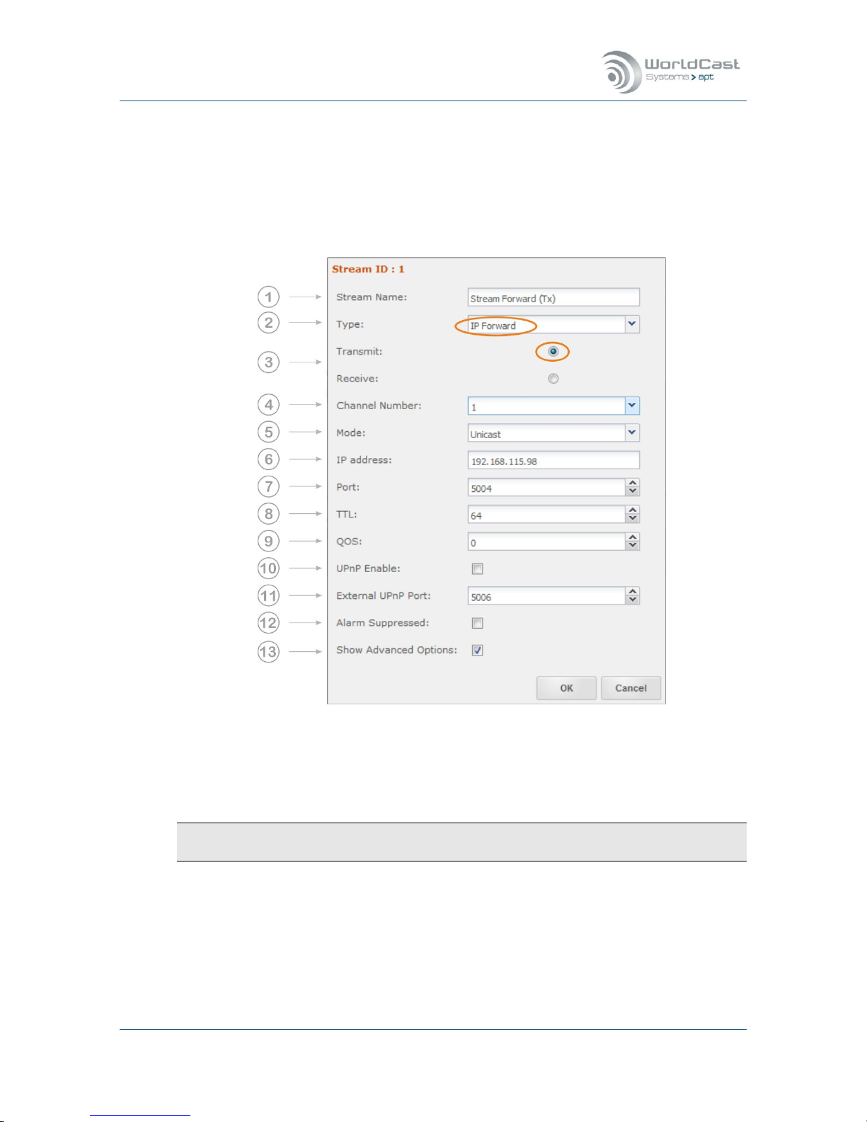
Silver Stream-In / Stream-Out - System Release 1.5.2 – April 2015
Page 60
Whiterock Business Park - 729 Springfield Road - Belfast BT12 7FP - Northern Ireland
Tel.: +44 28 9067 7200 | Fax: +44 28 9067 7201 | www.aptcodecs.com | contact@aptcodecs.com
3.4.6.8 Forwarding an IP Stream (Tx)
A forwarded stream must have been received and made available first (refer to section
3.4.6.7). With this configuration an already received stream is forwarded to the next or final
destination. The IP Forwarding option is data agnostic. The configuration for audio or nonaudio data is the same.
Figure 3-26: Shows the configuration options for IP Forwarding
For “IP Forward” the data source is the “Channel Number”! The example above reads
from channel 1 and forward the IP stream.
IP Forwarding is available on both, on the Stream-In (Encoder Tx) and on the Stream-Out
(Decoder Rx)!

Silver Stream-In / Stream-Out - System Release 1.5.2 – April 2015
Page 61
Whiterock Business Park - 729 Springfield Road - Belfast BT12 7FP - Northern Ireland
Tel.: +44 28 9067 7200 | Fax: +44 28 9067 7201 | www.aptcodecs.com | contact@aptcodecs.com
Forwarding an IP Stream (Tx) (continued)
1. Name: Enter the name for this stream
2. Type: Select Stream Type: IP Forward
3. Select: Transmit (available on Stream-In and Stream-Out)
4. Channel Number: Six data channels are provided for stream forwarding. A channel rep-
resents the forwarding destination of a received stream or the data source for a transmit
stream (in IP forward mode). – Select a channel from which the stream should be forwarded (this is the content source).
5. Casting Mode: Unicast is a point-to-point connection. The stream can be received from
one device or transmitted to one device only. Multicast allows point-to-multi point
streaming (Tx) and uses the IGMP protocol for managing multicast joins and leaves.
6. IP-Address: Enter the destination IP address or the hostname of the remote unit.
For unicast: This is the unique IP address of the remote receiver or the gateway.
For unicast: Entering a hostname requires active Dynamic DNS (refer to section 3.5.3.2).
For multicast: Enter the multicast group address.
7. Port: This is the IP port number of the remote Codec (destination IP port). For audio
stream this will be a port in the 5000 range (refer to section 3.4.6 pos. 8). For non-audio
data it should be in the 4000 range (refer to section 3.4.6.4 pos. 6)
8. TTL: Time to live describes the number of network hops the packet can pass. Each pass-
es hop reduces the TTL number by 1. If the TTL value becomes 0 and has not reached
the destination, it will be deleted. This avoids flooding the network with “blind” packets.
9. QoS: Quality of Service: If the network supports QoS mechanisms (not the Internet), the
here entered values (DiffServ) can be evaluated by the QoS enabled routers. QoS defines
a mechanism for prioritizing this IP stream against other IP traffic in the network.
Note, QoS is a network feature, the Codec allows the QoS tagging of the stream only.
The range is from 0 (off) to 63 (highest priority). It is important to know about the QoS
implementation of the network, before entering a value – not all values will be accepted
by the network router.
10. UPnP Enable: This check box enables the UPnP IGD feature (refer to section 3.5.3.3)
11. External UPnP Port: If UPnP is enabled, on default the internal port equals the external
port. This is a 1:1 port mapping performed in the router. In some cases it might be necessary reconfiguring this. This setting allows an individual port mapping. It is recommended not to change the 1:1 assignment without good reason.
12. Alarms Suppressed: Enabling this check box suppresses all alarms generated by this
stream. Sometimes it is useful suppressing alarms on a stream which are not applicable
in the particular situation. This can be enabled for each stream individually.
13. Show Advanced Options: Allows changing from “Basic Options” to “Advanced Options”.
This tick box expands the configuration window.
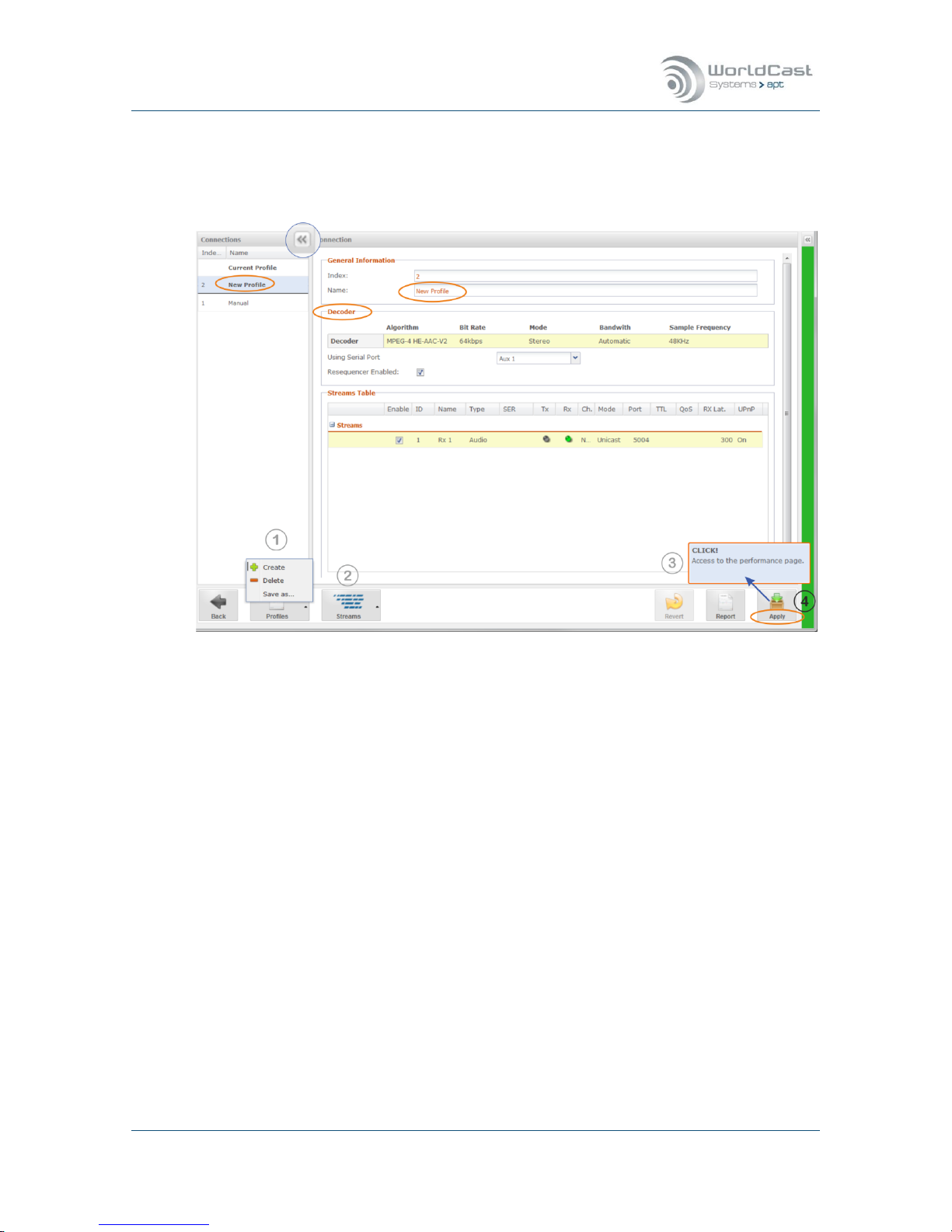
Silver Stream-In / Stream-Out - System Release 1.5.2 – April 2015
Page 62
Whiterock Business Park - 729 Springfield Road - Belfast BT12 7FP - Northern Ireland
Tel.: +44 28 9067 7200 | Fax: +44 28 9067 7201 | www.aptcodecs.com | contact@aptcodecs.com
3.4.7 Connection – Advanced Configuration
The “Advanced” configuration page can be opened directly from the Connection Page, or after the Configuration Wizard procedure was completed.
Figure 3-27: Shows the Advanced configuration window
The Connection Wizard as described earlier has created the “New Profile” from the audio set-
tings and the IP stream configurations. The “New Profile” now appears in the list of profiles
on the left hand side (Connections). This list of profiles is also accessible with the “Quick
Connection” tool. A click on the little arrow opens or closes the profile list.
The Advanced configuration page offers all options for creating new profiles or modifying an
existing one or deleting profiles from the list. It also allows changing the currently applied
(and active) configuration on the fly.

Silver Stream-In / Stream-Out - System Release 1.5.2 – April 2015
Page 63
Whiterock Business Park - 729 Springfield Road - Belfast BT12 7FP - Northern Ireland
Tel.: +44 28 9067 7200 | Fax: +44 28 9067 7201 | www.aptcodecs.com | contact@aptcodecs.com
Current Profile
“Current Profile” shows the currently active profile name. On the example above the cur-
rent profile is “New Profile”. Clicking on the headline “Current Profile” shows the currently
loaded profile on the configuration page in read-only mode. This cannot be changed at
this stage. Clicking on “New Profile” in this section loads the configuration of this profile
on the configuration page and can be edited but not deleted! If this profile was edited it
MUST be applied to the unit in order to save it. Saving the “Current” profile without ap-
plying it to the hardware is not possible, but it can be copied by using the “Save as…”
function (1).
Note: Applying a modified “Current” profile interrupts or disturbs an active transmission.
Editing Profile
Clicking on any other than “Current” profile in the list loads the configuration into the
main Connection Page. At this stage the profile can be modified (2) and saved by a click
on the “Save” button on the tool bar (3). This action does not affect the currently running
profile. The modified profile is now stored and can be applied to the hardware by clicking
on the Apply button (4).
Creating and Deleting a new Profile
Clicking on the “Create” button (1) creates a new and empty profile. A new configuration
can now be merged and saved to a new profile. Clicking the “Delete” button deletes a se-
lected profile from the list.
Copying a Profile
After a profile was selected from the list and loaded into the Connection Page it can be
copied by using the “Save as…” function (1). A new name must be applied to this profile.
Applying a Profile to the Codec
Clicking on a profile in the profile list loads the configuration into the Connection Page.
Clicking the “Apply” button (4) loads the profile to the Codec hardware and appears as
“Current Profile” in the list. This action always interrupts the IP transport.
After a profile was applied to the hardware a popup alert (3) appears providing a short
cut link to the Performance Page. This popup alert stays for several seconds and will disappear after a time out.

Silver Stream-In / Stream-Out - System Release 1.5.2 – April 2015
Page 64
Whiterock Business Park - 729 Springfield Road - Belfast BT12 7FP - Northern Ireland
Tel.: +44 28 9067 7200 | Fax: +44 28 9067 7201 | www.aptcodecs.com | contact@aptcodecs.com
3.4.8 Validation Engine
The Validation (Valex) Engine protects the user against incorrect inputs and obvious configuration mistakes. It validates IP stream configurations made on the local unit in terms of consistency and correctness.
The Valex Engine cannot judge e.g. wrong destination IP addresses, or inconsistent configurations on a local encoder compared with a remote decoder.
The image below shows and example about how the Valex Engine intervenes and how it presents information about mistakes on the GUI.
Figure 3-28: Shows how the Validation Engine presents error conditions and warnings
The detected mistake on this example is the disabled Decoder while an Rx stream is enabled
and assigned to an ETH port. The Valex Engine highlights the mistake as error on all affected
instances; i.e., on the “Codec disabled” setting and on the enabled Rx stream on the table. A
mouse over event pops up a clear error description.
Whenever a mistake is detected the validation report appears automatically and lists all instances where the mistake takes effect.

Silver Stream-In / Stream-Out - System Release 1.5.2 – April 2015
Page 65
Whiterock Business Park - 729 Springfield Road - Belfast BT12 7FP - Northern Ireland
Tel.: +44 28 9067 7200 | Fax: +44 28 9067 7201 | www.aptcodecs.com | contact@aptcodecs.com
Validation Engine (continued)
The image below shows another example about how the validation engine warns for critical
configurations.
Figure 3-29: Shows a yellow warning from the Validation Engine
The Validation Engine identified a problem on this profile configuration. On this configuration
example the de-jitter buffer was set to 200 ms. The Valex Engine has calculated 42.67 ms of
audio in a packet and indicates that the buffer must take at least 6 packets in order to get
the full performance from the re-sequencer. Either the buffer size must be set to 257 ms (6x
42.67 ms = 256.02 ms) or the re-sequencer should be disabled (not recommended).
This is a “Yellow” warning and not a critical alarm. The validation report does not pop up automatically, but with a mouse over on the highlighted fields the warning will be presented.
Due to the nature of the Validation Engine, it cannot foresee a misconfiguration especially on
a Rx stream before the configuration was applied and becomes active. On the example above
the Valex Engine must firstly receive packets before the required buffer size can be calculated.

Silver Stream-In / Stream-Out - System Release 1.5.2 – April 2015
Page 66
Whiterock Business Park - 729 Springfield Road - Belfast BT12 7FP - Northern Ireland
Tel.: +44 28 9067 7200 | Fax: +44 28 9067 7201 | www.aptcodecs.com | contact@aptcodecs.com
3.5 Main Menu – System
This section provides the general system setup items and sub menus.
3.5.1 Date and Time
The Silver Streamer runs its own internal timing reference. This reference is always UTC.
This UTC reference can be set either manually or via the NTP Client. The System Time
where all timing related actions are referring to is derived from this UTC timing reference
taking into account the Time Zone shift.
System current date and time
This section is read only and shows the current system date and time calculated from the
selected timing references below.
Set Date and Time
Date and Time entered here set the System Time in reference to the selected Time Zone:
Manually entered time +/- Time Zone = UTC timing reference
UTC +/- Time Zone = System Time
Set System Time Zone
Select the time zone where the unit is installed.
The Time Zone setting influences the local System Time. The System Time is calculated
from the UTC and the Time Zone shift. If the Time Zone is set correctly, the Date/Time
entry re-sets the UTC timing reference correctly. If the Time Zone is set wrong, then the
UTC time is calculated accordingly: NTP time = UTC timing reference
UTC timing reference +/- Time Zone = System Time
NTP Client Settings
This entry allows enabling/disabling the NTP client (Network Time Protocol) as well as entering the NTP server IP address.
If the NTP Client is enabled (“Yes”) the internal timing reference will be synchronized
with the NTP time reference (always UTC). This synchronization action is a single process
whenever the client is enabled. The NTP Client starts the synchronization process after a
randomly configured delay. Once the NTP reference was applied to the internal timing
reference the NTP protocol does not periodically re-synchronize the internal time. It rather adjusts the system clock to stay in sync with the NTP reference. In cases where the
timing is totally out of sync from the NTP reference, a re-synchronization can be forced
be disabling and re-enabling the NTP Client.
It is important to set the Time Zone correctly; otherwise the NTP Client (when enabled)
may change the System time unintended:
Any setting on this page must be saved before it becomes active on the hardware.

Silver Stream-In / Stream-Out - System Release 1.5.2 – April 2015
Page 67
Whiterock Business Park - 729 Springfield Road - Belfast BT12 7FP - Northern Ireland
Tel.: +44 28 9067 7200 | Fax: +44 28 9067 7201 | www.aptcodecs.com | contact@aptcodecs.com
3.5.2 User Management
Web Accounts
The user management offers a two-level hierarchy. The Administrator account allows full
access to the entire system, while the Read-Only Account (Guest) may be used for monitoring purposes only.
Do not forget to change the default password before connecting to an unprotected net-
work!
The user management allows only one Admin user being logged in. If another Admin user
tries to connect from another seat while the first Admin user is logged in, this second
LogIn attempt will be treated like a Guest user (read only)
3.5.3 Network Settings
This section consists of three pages organized by three tabs on the top:
Network settings
Dynamic DNS
UPnP configuration.
3.5.3.1 Network Page
This page shows the manually entered network configuration and the current network settings provided by a DHCP server, if enabled.
Figure 3-30: Shows the options on the Network configuration page
Text entries in grey are read-write; text in orange is read-only and set by the system

Silver Stream-In / Stream-Out - System Release 1.5.2 – April 2015
Page 68
Whiterock Business Park - 729 Springfield Road - Belfast BT12 7FP - Northern Ireland
Tel.: +44 28 9067 7200 | Fax: +44 28 9067 7201 | www.aptcodecs.com | contact@aptcodecs.com
Network Page (continued)
(1) Ethernet Configuration Mode
For IP interface ETH0 the mode can be chosen:
1. Static Mode for manual IP address settings
2. DHCP Mode that takes the IP settings from a DHCP server
Sections (2 & 3) show the “Current” Status and the “Static Configurations” for the ETH ports.
In dependence of the configuration mode the “Current Status” shows either the static configuration (manually edited) or the configuration applied by a DHCP server while keeping the
static settings in memory.
(2) Static configuration for ETH0
1. IP Address – this is the static (non-DHCP) IP address for your unit
2. Netmask – a static Netmask in accordance with your network configuration
3. Gateway – necessary if a gateway is configured in the network
4. MAC address displayed (read only)
(2) Current Status for ETH0
These currently valid values are set by either the DHCP server (in DHCP mode) or taken
from the static configuration values in static mode. If the DHCP client is active, the static
configuration stays available and must not be entered again when the mode has changed
to “Static”.
(3) DNS Server Status
5. Primary DNS from static or DHCP mode
6. Secondary DNS from static or DHCP mode
On static IP address settings, these DNS addresses must be entered manually. In DHCP
mode it will read from the DHCP server and displayed.
Notes:
____________________________________________________________
____________________________________________________________
____________________________________________________________
____________________________________________________________
____________________________________________________________
____________________________________________________________
____________________________________________________________
____________________________________________________________
____________________________________________________________

Silver Stream-In / Stream-Out - System Release 1.5.2 – April 2015
Page 69
Whiterock Business Park - 729 Springfield Road - Belfast BT12 7FP - Northern Ireland
Tel.: +44 28 9067 7200 | Fax: +44 28 9067 7201 | www.aptcodecs.com | contact@aptcodecs.com
3.5.3.2 Dynamic DNS
Dynamic DNS is a method of automatically updating a name server in the Domain Name
System (DNS) with the active DNS configuration of a configured hostname, address or other
information.
The NextGen Codec devices offer an integrated Dynamic DNS client allowing communication
with the most popular Dynamic DNS service providers. With this service enabled, each network interface of the audio codec can be addressed (in a WAN environment) independently
of its allocated numeric IP WAN address. Each interface should be configured with a unique
hostname that can be used instead of a destination IP address for WAN-based audio streaming.
Usually on xDSL lines, the DSL router receives an allocation of IP address by the Internet
service provider. The assigned address may either be fixed (static), or may change from time
to time (dynamic).
Once a hostname is registered and applied to an interface this hostname can be used on
the streams table as destination address. Regardless of where the unit is globally connected, the stream will find this Codec automatically.
The screen shot below shows the Dynamic DNS configuration page. Before this DDNS client
can be used, at least one hostname must have been registered on one of the DDNS services
provided on the drop down list (1).
Figure 3-31: shows the Dynamic DNS client settings and status information

Silver Stream-In / Stream-Out - System Release 1.5.2 – April 2015
Page 70
Whiterock Business Park - 729 Springfield Road - Belfast BT12 7FP - Northern Ireland
Tel.: +44 28 9067 7200 | Fax: +44 28 9067 7201 | www.aptcodecs.com | contact@aptcodecs.com
Dynamic DNS (continued)
The example above uses the No-IP service (www.noip.com). With the user name and the
password the client connects to this DDNS service provider if the “Enable” checkbox is ticked
on the ETH port and the entries were saved.
The registered hostname for the Codec interface for this example is: wcs-I000011
The full hostname entry for the No-IP account is: wcs-P000011.no-ip.org.
Once DDNS is enabled, the software client automatically enters the external IP address of
the current Link in the “NAT Address” field (2) – this is for information only (read-only field).
Further the status field presents messages from the DDNS provider if applicable. This can be
error messages or other information.
The stylized LED on top of this field indicates the status of the DDNS service:
Green: active and ok
Red: active but not ok
Grey: inactive (not enabled)
Example of an error message from the status field:
Figure 3-32: Shows an error message of the DDNS status
This error message was caused by having no DNS server information entered in the network
configuration page. The messages are almost in clear words and guide to the current misconfiguration.

Silver Stream-In / Stream-Out - System Release 1.5.2 – April 2015
Page 71
Whiterock Business Park - 729 Springfield Road - Belfast BT12 7FP - Northern Ireland
Tel.: +44 28 9067 7200 | Fax: +44 28 9067 7201 | www.aptcodecs.com | contact@aptcodecs.com
3.5.3.3 NAT Traversal Mode – UPnP
The NAT traversal mode enables the codec to request port mappings from an Internet Gateway device using a sub-section of the UPnP protocol (Universal Plug and Play) called the Internet Gateway Device Protocol (IGD Protocol).
IGD is the only part of the UPnP protocol which is used in the Codec device.
When enabled in a router, this allows an UPnP-enabled device to request port mappings to
be added and removed automatically without the need to maintain a configuration on the
router itself - allowing for ease of maintenance and a single device for configuration. Router
configurations do not need to be backed up or transferred etc.
IGD protocol, provided by UPnP, ensures that port mapping operations are “hidden” from the
user and allows a seamless plug and play operation. No server assistance or specific network
infrastructure is required
On the WEB GUI, there are two instances requiring entries from the user for UPnP. For audio
streaming, the configuration has to be done on the stream configuration window (refer to
section 3.4.5). For general settings the UPnP page provides the controls as shown on the
screen shot below.
Figure 3-33: shows the general UPnP port settings
This page allows the manual port mapping of common services utilized by the Codec.
At least forwarding of port 80 must be enabled for a Codec access from the WAN (from
external). Each Codec connected to the same Gateway must be configured individually.
A unique port number must be assigned to each device only. E.g., for port 80:
Single Codec - 80/80 (external port 80 is forwarded to the internal port 80)
Multiple Codecs - A: 80/8080 B: 80/8081 and so on. On the WEB browser any other port
than port 80 must be added to the external IP address: e.g. 217.117.10.10:8080.
This rule is the same for all ports listed on the screen shot above.

Silver Stream-In / Stream-Out - System Release 1.5.2 – April 2015
Page 72
Whiterock Business Park - 729 Springfield Road - Belfast BT12 7FP - Northern Ireland
Tel.: +44 28 9067 7200 | Fax: +44 28 9067 7201 | www.aptcodecs.com | contact@aptcodecs.com
3.5.4 mDNS Server – Look Up
DNS look up allows the connection to the unit in a local LAN without knowing the current IP
address! Using mDNS requires Zeroconf installed on the PC. The Easiest solution for this is to
install Apple's implementation of Zeroconf for Windows (Bonjour Service). In the case that
DHCP must be used in order to get a network access, the DNS look up feature may help to
identify the current IP address of the unit that was dynamically applied. With DNS look up
the unit can be accessed by using the mDNS name for the browser navigation.
Your management PC must be connected to the same network as your codec unit and
“Zeroconf” must be installed on your PC.
For the Silver Streamer the mDNS name has this format:
For System Release 1.0.4:
wcsphoenixSerialNumber.local – e.g. for a Silver Stream-In with serial number I000011:
http://wcsphoenixI000011.local
Since System Release 1.1.0:
The syntax has been changed on SR 1.1.0
wcs-SerialNumber.local – e.g. for a Silver Stream-In with serial number I000011:
http://wcs-I000011.local
The serial number is available on all production units on a label at the rear of the units.
The “.local” domain is the standard domain of your PC.
3.5.5 Diagnostic Page
Restart
This forces a unit Reboot – the unit will reboot without configuration changes.
Default Configuration
Resets the System and sets all Configurations to factory defaults but keeps the IP address settings.
The “Reset System to Default Configuration” action deletes all profiles ScriptEasy Scripts
(save first!) and all other user configurations BUT NOT the IP address!
FTP Service
This is an administrator function – FTP should be off all the time due to security considerations. FTP is only required when ScriptEasy (optional) uploads a script to the Codec.
After a reboot of the system the FTP service will be disabled on default.
Please ensure that FTP is disabled for normal operation!

Silver Stream-In / Stream-Out - System Release 1.5.2 – April 2015
Page 73
Whiterock Business Park - 729 Springfield Road - Belfast BT12 7FP - Northern Ireland
Tel.: +44 28 9067 7200 | Fax: +44 28 9067 7201 | www.aptcodecs.com | contact@aptcodecs.com
3.5.6 SMTP (Mail Setup)
The Silver Streamer supports email alerts on pre-configured operational conditions. E.g. any
alarm condition can send an email message to one or more addresses.
Figure 3-34: Shows the SMTP (email) configuration page
Basically this configuration page follows a standard procedure for setting up an email account. Once this configuration is completed and tested the mail alert feature can be used on
the alarm configurations. This page provides an option for sending a test mail. The content of
an alert email consist of system variables that cannot be changed. A variable is inside a curly
bracket. All other content can be changed or added if desired.
E.g.: {NAME} ({DESCRIPTION}) can also be: (My {NAME}) (unit type: {DESCRIPTION})
Standard System Variables:
7. {NAME}: Unit name which was applied to the unit
8. {FIRSTALARM}: Alarm Status (Alarm active / Alarm cleared)
9. {DESCRIPTION}: Information about unit Type i.e., Stream In or Stream Out
10. {SERIALNUMBER}: Serial number of alarming unit
11. {LOCALADDRESS}: IP address of alarming unit
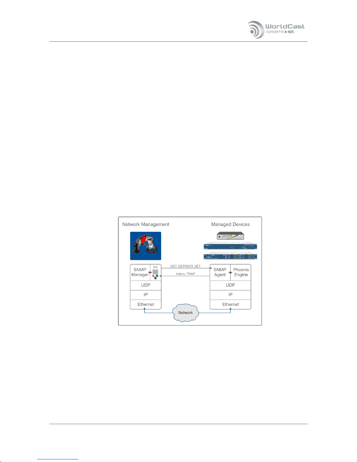
Silver Stream-In / Stream-Out - System Release 1.5.2 – April 2015
Page 74
Whiterock Business Park - 729 Springfield Road - Belfast BT12 7FP - Northern Ireland
Tel.: +44 28 9067 7200 | Fax: +44 28 9067 7201 | www.aptcodecs.com | contact@aptcodecs.com
3.5.7 SNMP
SNMP has been enabled as standard on all NextGen Codecs. WorldCast Systems’ SNMP implementation supports both SNMPv1 and SNMPv2c.
SNMP (Simple Network Management Protocol) is an interface used to control and to monitor
network elements. The Simple Network Management Protocol (SNMP) is an application layer
protocol that facilitates the exchange of management information between network devices.
It is part of the Transmission Control Protocol/Internet Protocol (TCP/IP) protocol suite.
The GET, GETNEXT and SET operations used in SNMPv1 are exactly the same as those used
in SNMPv2. However, SNMPv2 adds and enhances some protocol operations. The SNMPv2
Trap operation, for example, serves the same function as that used in SNMPv1, but it uses a
different message format and is designed to replace the SNMPv1 Trap.
The WorldCast Systems MIB files comply with the SNMPv2c-SMI (Structure of Management
Information) and preliminary allow polling for status and alarm conditions and to SET configuration profiles. The philosophy is that SNMP is used to manage alarm conditions and to reconfigure a unit by loading pre-configured profiles via SET commands.
The configuration of the audio Codecs is preferred and better suited to the Codec Management WEB GUI. Therefore the SNMP implementation is mainly designed for alarm and error
management.
Two MIB files are delivered with the firmware release. The common company MIB that must
be mandatorily loaded to the SNMP manager and the particular unit MIB file.
Figure 3-35: Shows the principal of SNMP communication
SNMP RFC compliances
- RFC 1901 Introduction to Community-based SNMPv2c
- RFC 1905 (replaced 1448) Protocol Operations for version 2 of SNMP (SNMPv2c)
- RFC 1213 Management Information Base for TCP/IP based networks: MIB-II
- RFC 1215 Convention for defining traps for use with the SNMP
- RFC 1442 Structure of Information for SNMPvc2 (SMI)
- RFC 2579 Textual Conventions for SMIv2

Silver Stream-In / Stream-Out - System Release 1.5.2 – April 2015
Page 75
Whiterock Business Park - 729 Springfield Road - Belfast BT12 7FP - Northern Ireland
Tel.: +44 28 9067 7200 | Fax: +44 28 9067 7201 | www.aptcodecs.com | contact@aptcodecs.com
3.5.7.1 SNMP Agent
This page will be presented from the Main Menu and provides the configuration options of the
inbuilt SNMP agent. These are the basic settings to get the SNMP protocol connected to the
SNMP manager. The Trap configuration page and the notification management are accessible
from page tabs.
Figure 3-36: Shows the SNMP-Agent configuration page
SNMP options on this page
1. SNMP Manager IP address: this is the IP address where Traps will be sent (port 162)
2. Optional Mirror 1-3: these are entry fields for more trap destination IP addresses
3. Community Get: this is the public community; any name can be entered here (con-
nect to port 161)
4. Community SET: this is the private community; any name can be entered here (con-
nect to port 161)
5. SNMP Master – check box
6. Life Sign Trap: this is keep-alive trap (heart beat) and can be enabled, disabled and
managed here.
For security reasons it is strongly recommended NOT to use the default names of com-
munity strings! Enter some more cryptic names instead!

Silver Stream-In / Stream-Out - System Release 1.5.2 – April 2015
Page 76
Whiterock Business Park - 729 Springfield Road - Belfast BT12 7FP - Northern Ireland
Tel.: +44 28 9067 7200 | Fax: +44 28 9067 7201 | www.aptcodecs.com | contact@aptcodecs.com
SNMP Agent (continued)
SNMP Traps
1. Notification Type: this can be TRAPs SNMPv1, SNMPv2c or Inform notification
SNMPv2c (sent on port 162)
2. Trap community: some SNMP manager offer a selection of trap communities
3. Trap sending test: clicking on this button sends an empty trap for connectivity test.
3.5.7.2 SNMP Trap Management
This page allows a precise trap management for each individual alarm condition. The list of
traps represents all available alarms of the system. Clicking on the little arrow beside the
name of traps opens the individual configuration options.
Figure 3-37: Shows the trap management page.
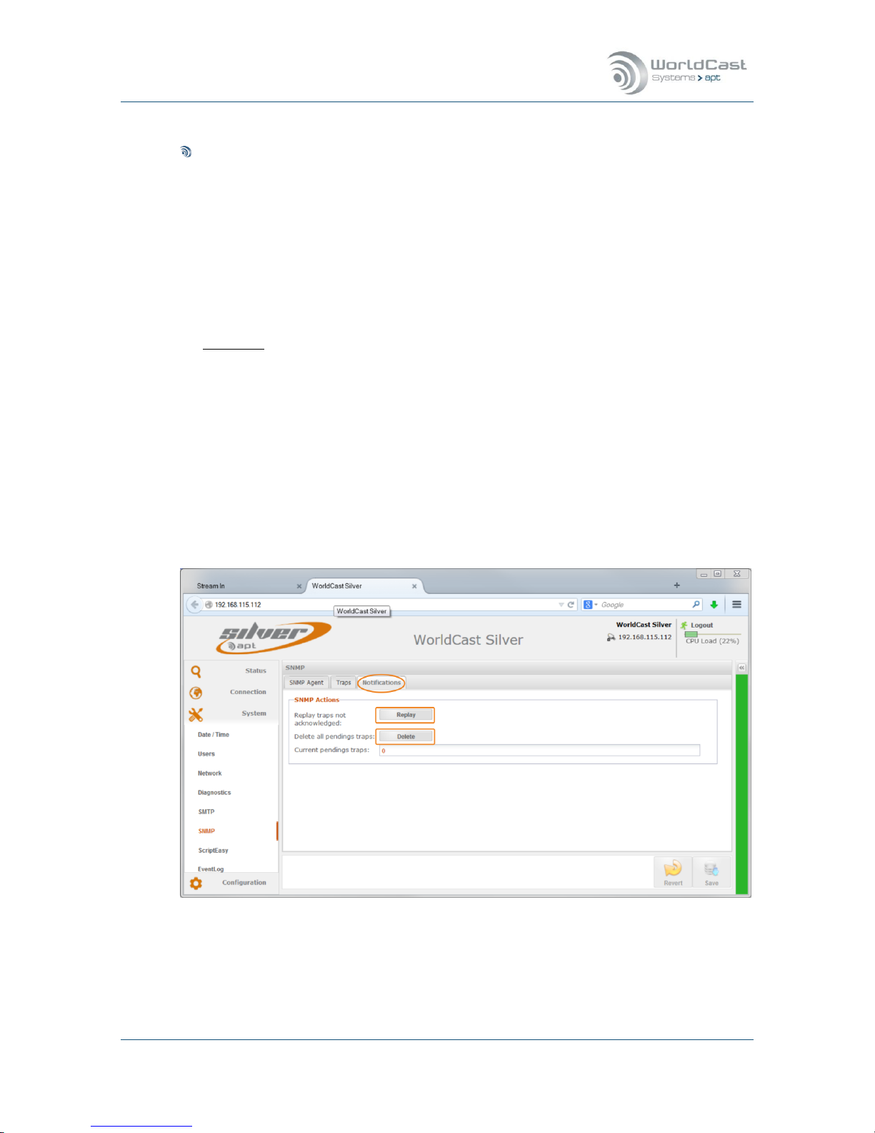
Silver Stream-In / Stream-Out - System Release 1.5.2 – April 2015
Page 77
Whiterock Business Park - 729 Springfield Road - Belfast BT12 7FP - Northern Ireland
Tel.: +44 28 9067 7200 | Fax: +44 28 9067 7201 | www.aptcodecs.com | contact@aptcodecs.com
SNMP Trap Management (continued)
For each alarm the trap sending behavior can be controlled:
1. Send and Forget: this option sends a trap once and expect no acknowledgement
from the SNMP Manager
2. Resend until acknowledged: this option expects an acknowledgement from the SNMP
Manager (for SNMPv2 only).
- Ack Timeout: defines the time window in which an acknowledgement must arrive
- Max. Attempts: defines the number of sending attempts if the acknowledgement
was not received within the pre-configured time window.
Important: “Resend until acknowledged” is a feature of SNMPv2 only! If this is selected
make sure that the SNMP manager can cope with acknowledgement requests. Be aware
that the number of Traps re-sent without acknowledgement may overload the memory!
This page allows controlling the general sending behavior of a trap, if a particular alarm
notification (TRAP) should be sent or not must be configured on the alarm configuration
page (refer to section 3.6.4).
3.5.7.3 SNMP Notifications Management
The third tab on the SNMP page allows control of the SNMP pending actions. A pending action is a non-acknowledged trap. This trap is stored in the unit until it was deleted on this
page.
Figure 3-38: Shows the Notifications management page
This page provides information of pending traps which were not acknowledged since they
were sent in accordance with the trap sending configuration (no. of attempts and timeout).
These traps can be deleted or re-sent.
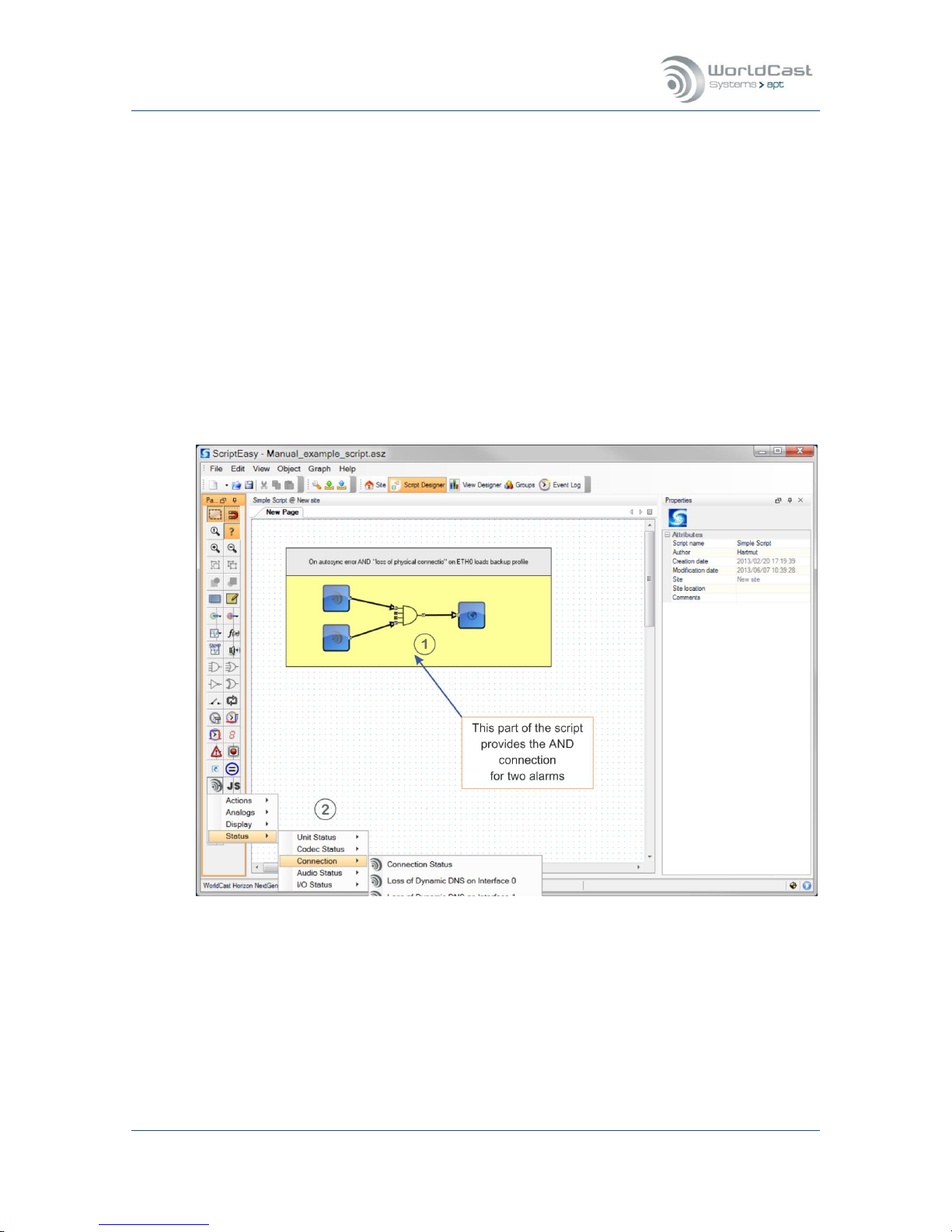
Silver Stream-In / Stream-Out - System Release 1.5.2 – April 2015
Page 78
Whiterock Business Park - 729 Springfield Road - Belfast BT12 7FP - Northern Ireland
Tel.: +44 28 9067 7200 | Fax: +44 28 9067 7201 | www.aptcodecs.com | contact@aptcodecs.com
3.5.8 System – ScriptEasy
3.5.8.1 About ScriptEasy
Since system release 1.1.0 all NextGen Codecs can be controlled by WorldCast Systems’
powerful scripting language “ScriptEasy”. ScriptEasy must be licensed and doesn’t come as a
standard feature. With the license the full user/developer manual is provided.
ScriptEasy enables the user to setup a precise Codec behavior dependent of pre-defined
conditions. It allows to link and combine features to operational conditions, e.g. a combination of alarm conditions can re-configure the unit (1), etc. etc.
ScriptEasy comes with as a separate PC application and consists of a graphical script designer and the MasterView dashboard viewer. The IDE (Integrated Development Environment)
allows to create the logic of a script and the view designer is used to design individual dashboards. A dashboard can be used, but it is not mandatory. The following screen shot shows a
little example about how ScriptEasy can be used on a Silver Streamer.
Figure 3-39: Shows the ScriptEasy IDE with a sample script
The figure above shows a single script. The script resides on the Codec hardware and can be
controlled and monitored by a dashboard or from the unit conditions. The following section
discusses the sample script as shown above.
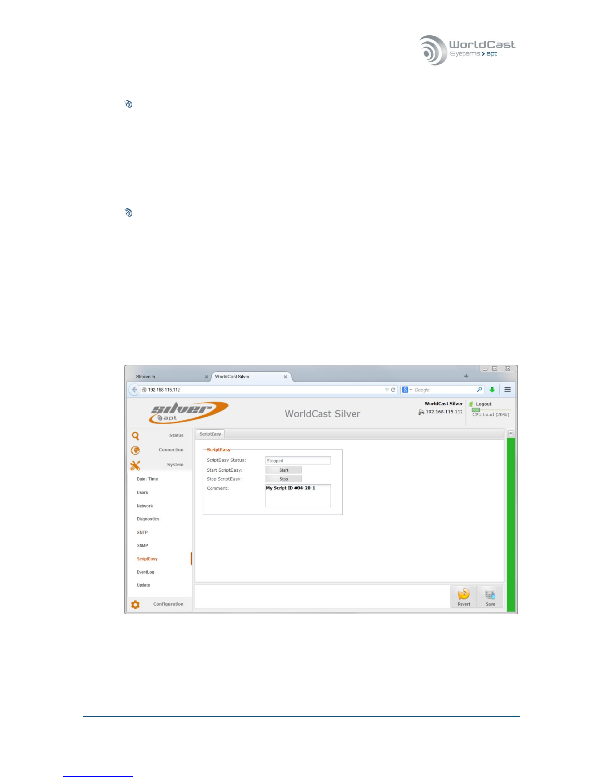
Silver Stream-In / Stream-Out - System Release 1.5.2 – April 2015
Page 79
Whiterock Business Park - 729 Springfield Road - Belfast BT12 7FP - Northern Ireland
Tel.: +44 28 9067 7200 | Fax: +44 28 9067 7201 | www.aptcodecs.com | contact@aptcodecs.com
3.5.8.2 ScriptEasy – Script Example
Example Script (1)
This part consists of four objects, the alarm status object for “Loss of physical connec-
tion”, an object for “AutoSync failure alarm”, the AND logic component and the “load pro-
file n” action object.
The AND connection avoids that the “AutoSync” alarm on its own changes to a particular
configuration. Only if both alarms occur then the new profile will be loaded which reroutes the IP streams to another source port (UDP port). AutoSync on its own can occur
for many reasons and must not necessarily point to an IP connectivity problem.
ScriptEasy Codec Objects (2)
The IDE provides a number of special objects used for the audio Codecs organized as status objects, input and output objects, action (set) objects for value manipulation and also
SNMP GET, SET and TRAP objects for external communication.
With the ScriptEasy license the full user/developer manual is provided.
3.5.8.3 ScriptEasy – Configuration
The ScriptEasy page in the system menu offers the controls for the loaded script.
Figure 3-40: Shows the ScriptEasy controls

Silver Stream-In / Stream-Out - System Release 1.5.2 – April 2015
Page 80
Whiterock Business Park - 729 Springfield Road - Belfast BT12 7FP - Northern Ireland
Tel.: +44 28 9067 7200 | Fax: +44 28 9067 7201 | www.aptcodecs.com | contact@aptcodecs.com
ScriptEasy – Configuration (continued)
The ScriptEasy page is used to start and to stop a loaded script. It shows the current status
and allows entering a comment that describes the script.
Once uploaded to the Codec the script becomes “invisible”. It starts whenever the units is
booted and can be stopped temporarily. If a script is loaded the WEB GUI shows a warning
when a user logs in. A script may overwrite user actions on its own!
A script becomes automatically active after system boot-up.
Only one script can be loaded.
A script can be stopped – but only temporarily. It becomes active again after re-boot!
ScriptEasy requires the FTP service for the initial script upload – make sure that FTP is
enabled (FTP is disabled on default).
3.5.8.4 ScriptEasy – Remove a Script
Once a script was uploaded to a unit it cannot be deleted again. In order to permanently deactivating a script, it must be overwritten by an empty script (a script without content).
Notes:
____________________________________________________________
____________________________________________________________
____________________________________________________________
____________________________________________________________
____________________________________________________________
____________________________________________________________
____________________________________________________________
____________________________________________________________
____________________________________________________________

Silver Stream-In / Stream-Out - System Release 1.5.2 – April 2015
Page 81
Whiterock Business Park - 729 Springfield Road - Belfast BT12 7FP - Northern Ireland
Tel.: +44 28 9067 7200 | Fax: +44 28 9067 7201 | www.aptcodecs.com | contact@aptcodecs.com
3.5.9 Event Log
A basic logging system is provided since system release 1.1.0. It records all events on a single log file that can be inspected, exported and deleted. A history page allows searching for
events in a defined time frame in order to limit the maximal shown log entries.
Figure 3-41: Shows Event Logs in the real time
This page shows the system event in real-time. It also provides a page tab for the history
search as well as the controls for deleting and exporting the log entries.
Notes:
____________________________________________________________
____________________________________________________________
____________________________________________________________
____________________________________________________________
____________________________________________________________
____________________________________________________________
____________________________________________________________
____________________________________________________________
____________________________________________________________
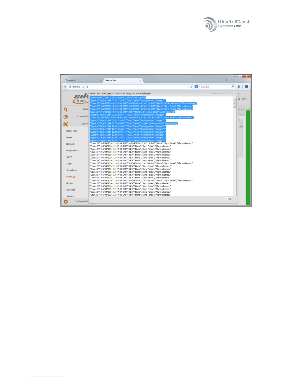
Silver Stream-In / Stream-Out - System Release 1.5.2 – April 2015
Page 82
Whiterock Business Park - 729 Springfield Road - Belfast BT12 7FP - Northern Ireland
Tel.: +44 28 9067 7200 | Fax: +44 28 9067 7201 | www.aptcodecs.com | contact@aptcodecs.com
3.5.9.1 Event Log Export
Clicking on the “Export in CSV” button opens a second window with all log entries. The content is formatted as a CSV file and can be exported to any spread sheet application by copy
and paste.
Figure 3-42: Shows the CSV formatted log file entries
Notes:
____________________________________________________________
____________________________________________________________
____________________________________________________________
____________________________________________________________
____________________________________________________________
____________________________________________________________
____________________________________________________________
____________________________________________________________
____________________________________________________________

Silver Stream-In / Stream-Out - System Release 1.5.2 – April 2015
Page 83
Whiterock Business Park - 729 Springfield Road - Belfast BT12 7FP - Northern Ireland
Tel.: +44 28 9067 7200 | Fax: +44 28 9067 7201 | www.aptcodecs.com | contact@aptcodecs.com
3.5.9.2 Event Log History
Clicking on the “History” tab opens a page that allows searching for entries in a defined period of time. Opening this page the first time it will present an empty page. Enabling the “Filter” check box opens the retrieval options.
Figure 3-43: Shows the history retrieval options
The search options allow the definition of a time period and the number of records that will
be presented. Clicking on the “Search” button starts the retrieval process. All records of the
specified time frame will be presented but limited by the previously chosen number of records.

Silver Stream-In / Stream-Out - System Release 1.5.2 – April 2015
Page 84
Whiterock Business Park - 729 Springfield Road - Belfast BT12 7FP - Northern Ireland
Tel.: +44 28 9067 7200 | Fax: +44 28 9067 7201 | www.aptcodecs.com | contact@aptcodecs.com
3.5.10 (Firmware) – Update
For a Firmware Update, section 5 MUST be consulted!
3.5.11 Licenses
This page provides the Unit Details necessary for creating and applying an option license. A
license options is e.g. ScriptEasy. A License which is already purchased and applied to the
unit will be displayed on this page.
For getting an option license key, the details displayed on this page must be forwarded to
the responsible sales office (MAC address and serial number). This can be done efficiently by
email. Clicking on the link “Request a ScriptEasy License” opens the standard email client of
the PC with the email address and MAC address already filled in. On the screen shot below,
both a ScriptEasy and a SureStream license are applied to the unit already.
Figure 3-44: Shows the unit parameter for getting an options license
Once the Unit Details are forwarded to the sales office, a Key-Code will be delivered. By
clicking on the “Add” button the “Add License” window appears where the Key-Code must be
entered and applied.
This Key is dedicated to the particular unit and cannot be transferred to any other unit. Once
the license key was applied, it cannot be removed and will not be overwritten by a firmware
update.

Silver Stream-In / Stream-Out - System Release 1.5.2 – April 2015
Page 85
Whiterock Business Park - 729 Springfield Road - Belfast BT12 7FP - Northern Ireland
Tel.: +44 28 9067 7200 | Fax: +44 28 9067 7201 | www.aptcodecs.com | contact@aptcodecs.com
3.5.12 System
On the “System” page the current unit hard- and software versions are shown
The entry field “Unit Name” allows entering an individual name for this particular unit. This
name appears on the browser tab as well as on the unit’s status page.
It also provides a little chat box that allows sending short messages to other actually logged
in users.
Figure 3-45: shows the "About" page of the System menu with Chat Box open
The chat box shows all currently logged in users regardless of the user status (Admin or
Guest). A message can be sent to any user by selecting the user first and typing a text in the
text area. The message will be sent after confirming with “Enter”.
On the receiving end the chat box pops up and presents the text message and the source
where this message comes from (see on next page).
The chat box uses UDP datagrams for sending these messages.
The user name which appears on the chat box is the “Screen Name” entered in the Log
In window.

Silver Stream-In / Stream-Out - System Release 1.5.2 – April 2015
Page 86
Whiterock Business Park - 729 Springfield Road - Belfast BT12 7FP - Northern Ireland
Tel.: +44 28 9067 7200 | Fax: +44 28 9067 7201 | www.aptcodecs.com | contact@aptcodecs.com
3.5.12.1 Chat Box
If a message is received the chat box pops up on any page which is currently open.
Figure 3-46: The chat box pops up when a message is received

Silver Stream-In / Stream-Out - System Release 1.5.2 – April 2015
Page 87
Whiterock Business Park - 729 Springfield Road - Belfast BT12 7FP - Northern Ireland
Tel.: +44 28 9067 7200 | Fax: +44 28 9067 7201 | www.aptcodecs.com | contact@aptcodecs.com
3.6 Main Menu – Configuration
The configuration menu provides four submenu items, the Audio Configuration page, Network Alarms, the AUX Data page and the alarm configuration page. These are basic configurations controlling operational modes and system behaviors
3.6.1 Audio Configurations
Stream-In – Encoder
Figure 3-47: Shows the Audio Configuration page in the Encoder (Stream-In RCA version)
All settings can be reverted or saved by clicking on either of the buttons as shows above.
The screenshot above shows the audio configuration page of a Stream-In Encoder with RCA
connectors. The XLR version allows changing the Input or Output impedance in addition. The
table below outlines the configuration options on both versions.
Notes:
__________________________________________________________________________
__________________________________________________________________________
__________________________________________________________________________
__________________________________________________________________________
_______________________________________________________________________

Silver Stream-In / Stream-Out - System Release 1.5.2 – April 2015
Page 88
Whiterock Business Park - 729 Springfield Road - Belfast BT12 7FP - Northern Ireland
Tel.: +44 28 9067 7200 | Fax: +44 28 9067 7201 | www.aptcodecs.com | contact@aptcodecs.com
Stream-Out – Decoder (only)
Figure 3-48: Shows the Audio Configuration page in the Decoder (Stream-Out RCA version)
All settings can be reverted or saved by clicking on either of the buttons as shows above.
The screenshot above shows the audio configuration page of a Stream-Out Decoder with RCA
connectors. The XLR version allows changing the Input or Output impedance in addition. The
table below outlines the configuration options on both versions.
Notes:
__________________________________________________________________________
__________________________________________________________________________
__________________________________________________________________________
__________________________________________________________________________
_______________________________________________________________________

Silver Stream-In / Stream-Out - System Release 1.5.2 – April 2015
Page 89
Whiterock Business Park - 729 Springfield Road - Belfast BT12 7FP - Northern Ireland
Tel.: +44 28 9067 7200 | Fax: +44 28 9067 7201 | www.aptcodecs.com | contact@aptcodecs.com
3.6.1.1 Audio Configuration Options
This section provides the following configuration options:
Configuration
Options
Description
RCA version:
Input Clip Level (dBu)
(Stream-In)
Values 0-10 dBu
Adjusts the analog Input level in reference
to the digital dBFS in increments of 0.1 dB
RCA version:
Output Clip Level (dBu)
(Stream-Out)
Values 0-10 dBu
Adjusts the analog Output level in reference
to the digital dBFS in increments of 0.1 dB
XLR version:
Input Clip Level (dBu)
(Stream-In)
Values 0-24 dBu
Adjusts the analog Input level in reference
to the digital dBFS in increments of 0.1 dB
XLR version:
Output Clip Level (dBu)
(Stream-Out)
Values 0-24 dBu
Adjusts the analog Output level in reference
to the digital dBFS in increments of 0.1 dB
XLR version:
Input Impedance
(Stream-In)
High
600 Ω
Analog Input impedance
In: >10 kΩ
Sets the Input impedance to 600 Ω
XLR version:
Output Impedance
(Stream-Out)
Low
600 Ω
Analog Output impedance
In: <50 Ω
Sets the Output impedance to 600 Ω
Mono Source Selection
(Stream-In)
Left Channel
only
Mono Sum
((L+R)/2)
This describes the signal source (input) for a
mono mode of an audio algorithm.
This selection takes both signals (left &
right) and divides it by 2 (-3 dB)
Mono Output Mode
(Stream-Out)
Mono Output
MonoFill 1)
Output on left channel only
MonoFill copies the signal also to the idle
channel; mono output on L & R connectors
Audio Alarm Input channel A/B
(Stream-In)
Enable/Disable
Threshold Level
Ticking the boxes enable Silence alarms
Level setting from -3 dBFS to -42 dBFS in in-
crements of 3 dB
Audio Alarm Output
channel C/D
(Stream-Out)
Enable/Disable
Threshold Level
Ticking the boxes enable Silence alarms
Level setting from -3 dBFS to -42 dBFS in increments of 3 dB
Timeout
(Stream-In/Out)
Value
This setting defines the period of time the
signal has to be below the threshold level
before the audio alarm is flagged.
1)
MonoFill cannot be used together with the advanced routing option as the two features
stay in a conflict.

Silver Stream-In / Stream-Out - System Release 1.5.2 – April 2015
Page 90
Whiterock Business Park - 729 Springfield Road - Belfast BT12 7FP - Northern Ireland
Tel.: +44 28 9067 7200 | Fax: +44 28 9067 7201 | www.aptcodecs.com | contact@aptcodecs.com
Analog Configuration (continued)
Analog I/O Clip Levels (XLR)
These settings allow adjusting the analog levels in reference to the digital level:
All level readings are internally referenced to the digital domain where 0 dBFS=24 dBu.
For example, if the analog level of +6 dBu shall internally equal -9 dBFS then the analog
clip level must be set to +15 dBu (0 dBFS =15 dBu hence -9 dBFS=+6 dBu).
Low Latency Mode
This “Low Latency Mode” effects the analog signal processing and improves the system
latency by approx. -1.5 ms. This mode disables and bypasses the input Sample Rate
Converter which is obsolete in these modes (Stream-In only):
- Linear PCM at F
s
= 48 kHz (any linear PCM mode that uses 48 kHz Sample Frequency)
- Eapt-X
®
at Fs = 48 kHz (any Eapt-X® mode that uses 48 kHz Sample Frequency)
Configuration
Options
Description
Low Latency Mode
Enable/Disable
Ticking this box enables the low latency
mode
Note: This latency improvement takes place on audio formats (as listed above) that run
at 48 kHz sampling frequency. Whenever another mode is selected, e.g. Linear PCM with
up to 15 kHz frequency response (equals Fs = 32kHz) then this mode is automatically
deactivated regardless of the enable/disable status on this configuration page. As long
as this mode is enabled it automatically takes place if an audio mode at 48 kHz is selected
.
Encoder Mono Mode
The Encoder mono setting takes effect only if a mono algorithm is selected. The mono
setting is ignored if a stereo algorithm is selected.
Encoder Source Selection:
- Left channel only
- Mono Sum ((L+R)/2)
Decoder Mono Output
The Decoder mono setting takes effect only if a mono algorithm is chosen (mono
stream). The mono setting is ignored if a stereo algorithm is selected.
- Mono Output (mono signal on left channel)
- Monofill (mono signal copy to Idle Channel)

Silver Stream-In / Stream-Out - System Release 1.5.2 – April 2015
Page 91
Whiterock Business Park - 729 Springfield Road - Belfast BT12 7FP - Northern Ireland
Tel.: +44 28 9067 7200 | Fax: +44 28 9067 7201 | www.aptcodecs.com | contact@aptcodecs.com
3.6.1.2 Advanced Routing & Decoder Mono Mode
With system release 1.4.0 the Decoder options (Stream-Out) are extended by two features
combined in the section “Advanced Routing”
1. Creation of Mono signals from incoming stereo IP streams
2. Advanced Routing of the output signal
Figure 3-49: Shows the principle of this feature of the Decoder
Decoder Mono Mode
This feature allows to create a mono signal (mono sum) from an incoming stereo stream.
The mono sum is performed in the Decoder section and does not affect the stereo IP stream.
Other than the mono sum option on the Encoder, the mono sum on the Decoder is algorithm
agnostic. In a distribution network, the same stereo program can be decoded as stereo feed
for e.g. FM supply and as a mono feed for an AM supply – the mono/stereo signal is generated from the same stereo stream.
Advanced Routing
This feature allows the routing of the decoded PCM signal from the DSP output to the physical output connectors on the rear panel of the Codec or Decoder. By default and if the advanced routing feature is disabled, the signals are routed 1:1. For more details refer to the
section below.
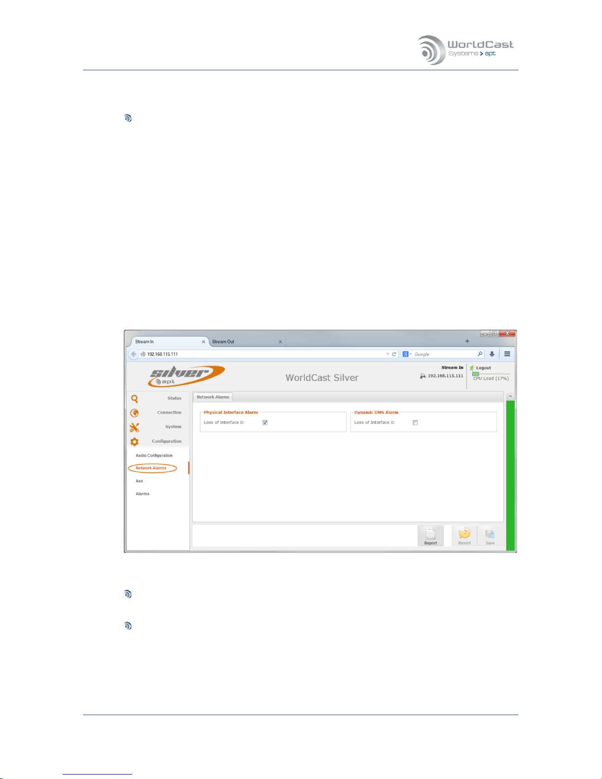
Silver Stream-In / Stream-Out - System Release 1.5.2 – April 2015
Page 92
Whiterock Business Park - 729 Springfield Road - Belfast BT12 7FP - Northern Ireland
Tel.: +44 28 9067 7200 | Fax: +44 28 9067 7201 | www.aptcodecs.com | contact@aptcodecs.com
Audio Configuration (continued)
Advanced Routing & Decoder Mono Mode
Advanced Routing must be enabled to become active by clicking the check box “Ad-
vanced Routing” and on “Save” on the bottom of the page.
“Output Signal C” and “Output Signal D” describe the physical outputs on the rear of the
codec (XLR L/R outputs).
The drop down list shows the available signals:
“Mono Sum – CD” this is the mono sum from the equation ((C+D)/2).
Signal “C” and “D” represent the signals L/R from the received stereo stream.
If enabled, the advanced routing and mono mode feature offers the mono signal on both
outputs C and D.
3.6.2 Network Alarms
This page provides the alarm options of the Ethernet interfaces and Dynamic DNS.
Figure 3-50: Alarm configuration options of Ethernet ports
Enable/Disable alarms for physical loss of connections.
If this alarm disabled, a physical loss of connection will not be recognized as alarm
Enable/Disable alarms of Dynamic DNS connection
If this alarm is disabled, a loss of connection to the dynamic DNS service will not be recognized as alarm; this option is disabled on default.
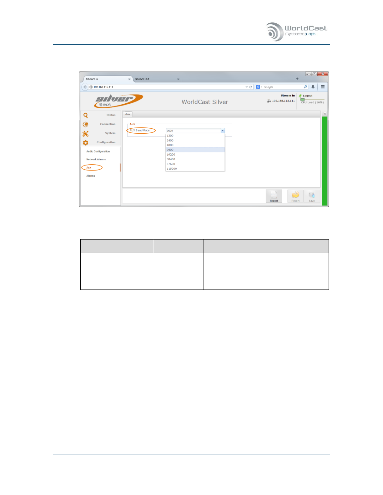
Silver Stream-In / Stream-Out - System Release 1.5.2 – April 2015
Page 93
Whiterock Business Park - 729 Springfield Road - Belfast BT12 7FP - Northern Ireland
Tel.: +44 28 9067 7200 | Fax: +44 28 9067 7201 | www.aptcodecs.com | contact@aptcodecs.com
3.6.3 AUX Data Configuration
Figure 3-51: Shows the AUX Data configuration
Configuration
Options
Description
AUX Data Baud Rate
(Stream-In/Out)
Value
The drop down list provides baud rate setting from 1.200 to 115.200 Baud (non-
embedded)
Embedded: up to 9600 Baud
The AUX data connection can be configured as duplex connection on the Stream Table.
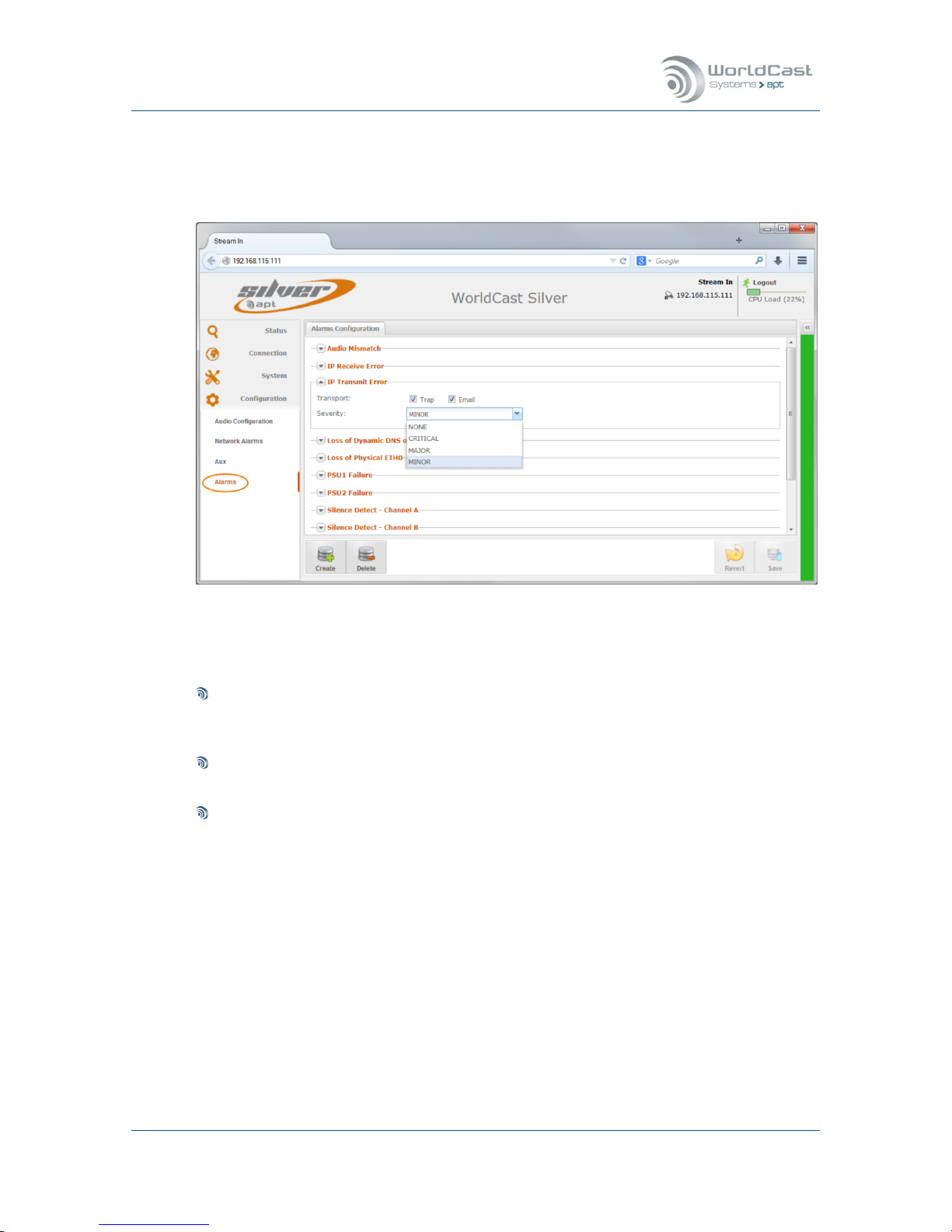
Silver Stream-In / Stream-Out - System Release 1.5.2 – April 2015
Page 94
Whiterock Business Park - 729 Springfield Road - Belfast BT12 7FP - Northern Ireland
Tel.: +44 28 9067 7200 | Fax: +44 28 9067 7201 | www.aptcodecs.com | contact@aptcodecs.com
3.6.4 Alarms Configuration
Since system release 1.1.0 all system alarms are configurable individually. The alarm configuration page shows all available alarms and provides option to control the alarm behavior.
Figure 3-52: Shows the Alarms Configuration page
All system alarms are listed here. Clicking on the little arrow beside each alarm opens the
configuration options. These options are:
Sending a SNMP trap
If this check box is enabled this alarm sends a trap to the SNMP manager. The trap management can be found on the SNMP page.
Sending an email alert
If this check box is enabled this alarm sends an email alert.
Severity
This drop down list presents the severity levels. The alarms will be presented on all instances in accordance with these settings.
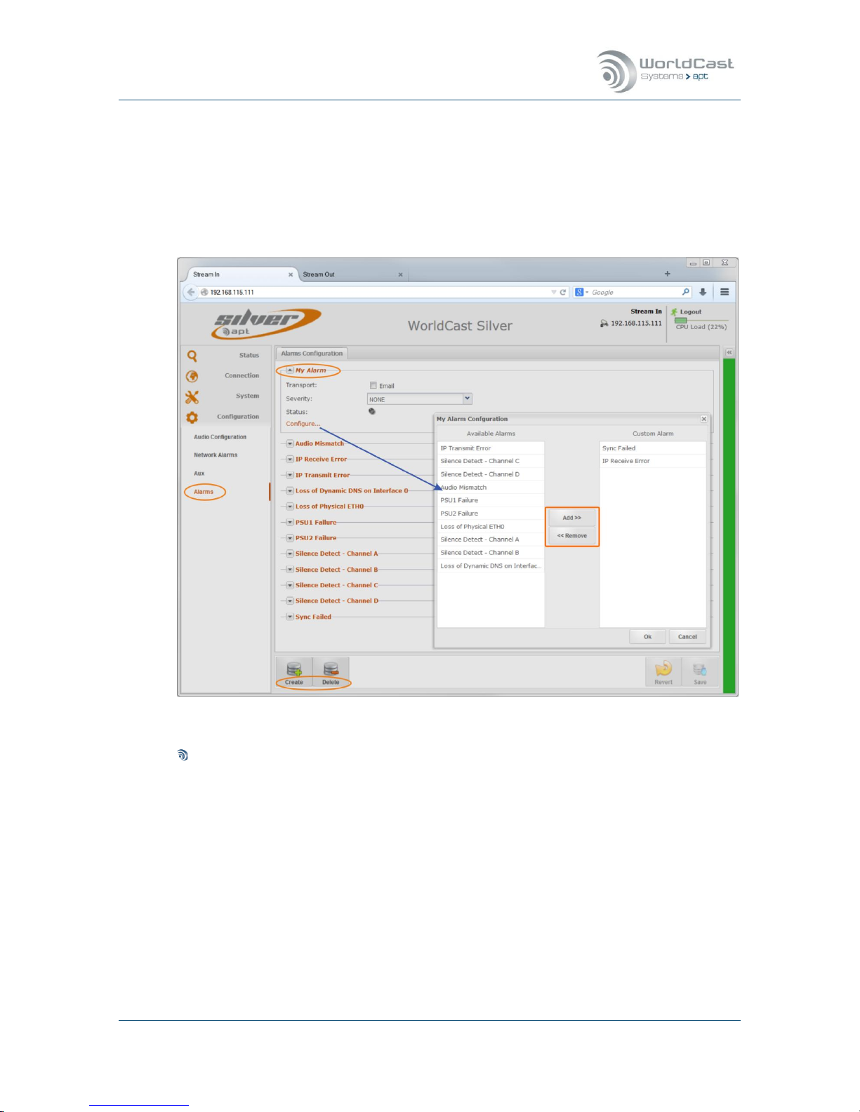
Silver Stream-In / Stream-Out - System Release 1.5.2 – April 2015
Page 95
Whiterock Business Park - 729 Springfield Road - Belfast BT12 7FP - Northern Ireland
Tel.: +44 28 9067 7200 | Fax: +44 28 9067 7201 | www.aptcodecs.com | contact@aptcodecs.com
3.6.5 Alarms - Customer Alarms
Creating an individual alarm allows to create groups of alarms which will be treated as a single alarm (OR logic). The advantage of this option is that a group of alarms (created here)
can be assigned to a single relay.
The alarm configuration page offers the option for creating and managing customer’s alarm
groups. The figure below shows an example for “My Alarm”.
Figure 3-53: Shows how to create an alarm group
How to create an Alarm group
1. Clicking on the “Create” button prompts you to enter a name for the alarm group
(My Alarms). After applying the name, this setting must be saved first before the
group can be configured.
2. After saving the “My Alarms” group, this alarm appears on the bottom of the list of
alarms. As many groups as required can be created.
3. Clicking on the little arrow beside opens the alarm options and the “Configure…” link.
4. Following the configuration link opens the Alarm configuration window. This window
shows all available alarms on the left hand side. Alarms can be added to the group
on the right hand side by selecting the desired alarms and clicking on the “Add” button.
5. Once this alarm group is created the email alert can be enabled, and this group can
be assigned to a relay.

Silver Stream-In / Stream-Out - System Release 1.5.2 – April 2015
Page 96
Whiterock Business Park - 729 Springfield Road - Belfast BT12 7FP - Northern Ireland
Tel.: +44 28 9067 7200 | Fax: +44 28 9067 7201 | www.aptcodecs.com | contact@aptcodecs.com
SureStream 4.0
SureStream Technology is a standard feature of the Silver IP Streamer range.
Figure 4-1: Shows the Status Page with SureStream enabled
4.1 About SureStream
SureStream Technology is a revolutionary innovation from APT that enables broadcasters to
use inexpensive IP links and still maintain professional broadcast-grade audio quality and reliability. It delivers the audio quality and reliability known from a synchronized TDM based
link at a fraction of the associated cost.
The technology approach of SureStream is based on redundant streaming. SureStream replicates a single program audio stream and passes it through the Statistical Diversity Generator. Following this process the redundant program streams appear on the network as unique
streams generated from different or the same source.
In practice a single stream will be duplicated on the IP port as SureStream component
streams. This feature works on a single physical port (like on the Silver Streamer Range) as
well as on Codec systems equipped with dual IP ports.
SureStream is highly efficient on potentially lossy networks like the public Internet. It can also be used for permanent redundant streaming on managed networks.
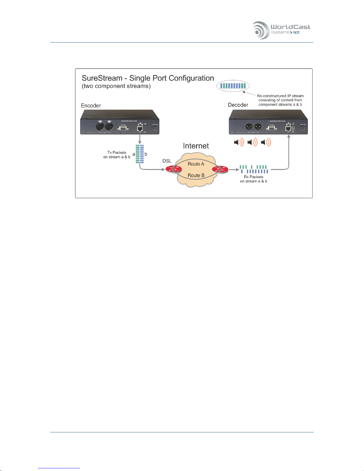
Silver Stream-In / Stream-Out - System Release 1.5.2 – April 2015
Page 97
Whiterock Business Park - 729 Springfield Road - Belfast BT12 7FP - Northern Ireland
Tel.: +44 28 9067 7200 | Fax: +44 28 9067 7201 | www.aptcodecs.com | contact@aptcodecs.com
About SureStream (continued)
Figure 4-2: Shows a typical configuration running SureStream on a single IP port
The configuration example above shows a typical SureStream configuration using two
SureStream component streams. This example uses the Internet with standard xDSL access
services. Diverse streaming on the internet has the effect, that the access routers treat each
SureStream component stream individually by passing it randomly on different paths to the
destination IP address.
On the receiving end, the Enhanced Re-Sequencer generates from all component streams
the single packet stream on a first-in-first-out packet basis. All duplicated/redundant packets
will be dropped. The number of component streams is not limited by the SureStream technology.
SureStream is a powerful algorithm that protects an IP link against packet losses and Loss of
Connection errors. The latter protection can be achieved only if the Codec device uses dual
IP ports for streaming out the component streams.
On a single IP port device, like the Stream-In and Stream-Out, SureStream cannot pro-
tect the IP link against Loss of Connection errors.

Silver Stream-In / Stream-Out - System Release 1.5.2 – April 2015
Page 98
Whiterock Business Park - 729 Springfield Road - Belfast BT12 7FP - Northern Ireland
Tel.: +44 28 9067 7200 | Fax: +44 28 9067 7201 | www.aptcodecs.com | contact@aptcodecs.com
About SureStream (continued)
4.1.1 SureStream Encoder
On the Encoder side the heart of SureStream is the Statistical Diversity Generator. This generator ensures that the component streams appear on the network as diverse as possible.
This generator runs an algorithm that can be set up with three different sets of parameters
(called “levels”) allowing the use of more than one component stream while keeping each
stream divers from each other.
4.1.2 SureStream Decoder
Once SureStream has generated duplicated streams with the same payload intended to
reach the same receiver, the Decoder on the receiving end must cope with a massive
amount of redundant packets arriving from a single or different networks. Allowing the Decoder to cope with duplicated packets it must run the complementary algorithm as on the
Encoder side; this is the Enhanced Packet Re-Sequencer Engine.
Notes:
____________________________________________________________
____________________________________________________________
____________________________________________________________
____________________________________________________________
____________________________________________________________
____________________________________________________________
____________________________________________________________

Silver Stream-In / Stream-Out - System Release 1.5.2 – April 2015
Page 99
Whiterock Business Park - 729 Springfield Road - Belfast BT12 7FP - Northern Ireland
Tel.: +44 28 9067 7200 | Fax: +44 28 9067 7201 | www.aptcodecs.com | contact@aptcodecs.com
4.2 SureStream – Encoder Configuration
Creating a SureStream component stream follows basically the same procedure as a normal
stream configuration. A set of component streams will be identified as part of a SureStream
group by the equal packet size. This is an important indication, because within a set of redundant streams the packet sizes must be equal. If a set of component streams are configured correctly, the connection page will indicate this by grouping the corresponding streams
(SureStream group). If the packet size is not equal on all component streams, the streams
will be treated separately and no SureStream group will be generated.
Figure 4-3: Shows a SureStream configuration on the Encoder
A SureStream group (i.e. SureStream 1) will be displayed only if the packet sizes on ALL
component streams are equal!
The figure above shows a working Encoder configuration in principal with two streams are
assigned to the same destination IP address, hence they are received on a single port at the
Decoder end. This implies that both streams are going out on the same ETH port on the Encoder into a single network. – In a real world application this configuration will protect the IP
link against packet losses very efficiently as explained above.
The next section outlines the recommended and mandatory settings for a group of component streams.

Silver Stream-In / Stream-Out - System Release 1.5.2 – April 2015
Page 100
Whiterock Business Park - 729 Springfield Road - Belfast BT12 7FP - Northern Ireland
Tel.: +44 28 9067 7200 | Fax: +44 28 9067 7201 | www.aptcodecs.com | contact@aptcodecs.com
SureStream – Encoder Configuration (continued)
Once the SureStream license was applied to the unit the Diversity Generator option appear
on the stream configuration window. Again, creating a group of component streams follows
the normal procedure.
Figure 4-4: Shows the Diversity Generator options on the stream configuration window
4.2.1 About Diversity Generator Levels
The SureStream Diversity Generator can be either disabled or set from “Level I” to “Level
III”. A “Level” does not indicate the level of severity of SureStream. A “Level” is a set of pa-
rameters used by the Diversity Generator to ensure the stream diversity. All three “Levels”
work on the same level of severity but differently from each other.
Having three sets of parameters allows to configuring more than one redundant stream and
keeping all streams processed individually by the Diversity Generator. It has been seen
sometimes that a particular “Level” delivers better results than another.
Therefore it is worthwhile to trying out what Level delivers the best results in a particular
network environment.
Whenever a set of SureStream component streams are created, one of them should
have the Diversity Generator Level set to off. All other component streams should run
on a different level (I-III).
 Loading...