


WORKSWELL
WIRIS 2
USER MANUAL
FW Version: 2.0.0
Release date: 24thJanuary, 2017
Revision : 1.0 EN

Contents
1. Introducon 3
1.1 Legal Disclaimer . . . . . . . . . . . . . . . . . . . . . . . . . . . . . . . . . . . . . . . . . . . 4
1.2 Copyright . . . . . . . . . . . . . . . . . . . . . . . . . . . . . . . . . . . . . . . . . . . . . . 4
2. Help and FAQ 5
2.1 General Instrucons . . . . . . . . . . . . . . . . . . . . . . . . . . . . . . . . . . . . . . . . . 5
3. User Informaon 6
3.1 Typographic Convenons . . . . . . . . . . . . . . . . . . . . . . . . . . . . . . . . . . . . . . 6
3.2 Help and Community Forum . . . . . . . . . . . . . . . . . . . . . . . . . . . . . . . . . . . . 6
3.3 Updates . . . . . . . . . . . . . . . . . . . . . . . . . . . . . . . . . . . . . . . . . . . . . . . 6
3.4 Firmware . . . . . . . . . . . . . . . . . . . . . . . . . . . . . . . . . . . . . . . . . . . . . . 6
4. Warning and Cauons 7
4.1 Warnings . . . . . . . . . . . . . . . . . . . . . . . . . . . . . . . . . . . . . . . . . . . . . . 7
4.2 Noficaons . . . . . . . . . . . . . . . . . . . . . . . . . . . . . . . . . . . . . . . . . . . . . 7
5. Revision History 8
6. System assembly 9
6.1 General Descripon . . . . . . . . . . . . . . . . . . . . . . . . . . . . . . . . . . . . . . . . . 9
6.2 Connecng the system to a wireless video link or display . . . . . . . . . . . . . . . . . . . . . 10
6.3 Connecng the system to a standard RC receiver . . . . . . . . . . . . . . . . . . . . . . . . . 10
6.4 USB 2.0 Keyboard . . . . . . . . . . . . . . . . . . . . . . . . . . . . . . . . . . . . . . . . . . 11
6.5 Connecng the power supply . . . . . . . . . . . . . . . . . . . . . . . . . . . . . . . . . . . . 11
6.6 Turning the system OFF . . . . . . . . . . . . . . . . . . . . . . . . . . . . . . . . . . . . . . . 12
6.7 Focusing the infrared camera . . . . . . . . . . . . . . . . . . . . . . . . . . . . . . . . . . . . 13
6.8 Mounng the system . . . . . . . . . . . . . . . . . . . . . . . . . . . . . . . . . . . . . . . . 14
6.9 GPS . . . . . . . . . . . . . . . . . . . . . . . . . . . . . . . . . . . . . . . . . . . . . . . . . 15
7. Digital IO Ports 17
7.1 General Descripon . . . . . . . . . . . . . . . . . . . . . . . . . . . . . . . . . . . . . . . . . 17
7.2 Hardware compability . . . . . . . . . . . . . . . . . . . . . . . . . . . . . . . . . . . . . . . 17
7.3 Digital Inputs . . . . . . . . . . . . . . . . . . . . . . . . . . . . . . . . . . . . . . . . . . . . 18
7.3.1 PWM mode . . . . . . . . . . . . . . . . . . . . . . . . . . . . . . . . . . . . . . . . . 18
7.3.2 Trigger mode . . . . . . . . . . . . . . . . . . . . . . . . . . . . . . . . . . . . . . . . 19
7.4 Digital Outputs . . . . . . . . . . . . . . . . . . . . . . . . . . . . . . . . . . . . . . . . . . . 19
8. System appearance 20
8.1 General Descripon . . . . . . . . . . . . . . . . . . . . . . . . . . . . . . . . . . . . . . . . . 20
9. System Menu (Sengs) 24
9.1 General Descripon . . . . . . . . . . . . . . . . . . . . . . . . . . . . . . . . . . . . . . . . . 24
9.2 Range . . . . . . . . . . . . . . . . . . . . . . . . . . . . . . . . . . . . . . . . . . . . . . . . 25
9.3 Isotherms . . . . . . . . . . . . . . . . . . . . . . . . . . . . . . . . . . . . . . . . . . . . . . 27
1

9.4 Funcons . . . . . . . . . . . . . . . . . . . . . . . . . . . . . . . . . . . . . . . . . . . . . . 30
9.5 Palee . . . . . . . . . . . . . . . . . . . . . . . . . . . . . . . . . . . . . . . . . . . . . . . . 31
9.6 Advanced . . . . . . . . . . . . . . . . . . . . . . . . . . . . . . . . . . . . . . . . . . . . . . 32
9.6.1 Measurement . . . . . . . . . . . . . . . . . . . . . . . . . . . . . . . . . . . . . . . . 33
9.6.2 Display . . . . . . . . . . . . . . . . . . . . . . . . . . . . . . . . . . . . . . . . . . . 33
9.6.3 Save Images . . . . . . . . . . . . . . . . . . . . . . . . . . . . . . . . . . . . . . . . . 35
9.6.4 Isotherms . . . . . . . . . . . . . . . . . . . . . . . . . . . . . . . . . . . . . . . . . . 36
9.6.5 Communicaon Interface . . . . . . . . . . . . . . . . . . . . . . . . . . . . . . . . . . 37
9.6.6 Memory . . . . . . . . . . . . . . . . . . . . . . . . . . . . . . . . . . . . . . . . . . . 39
9.6.7 System . . . . . . . . . . . . . . . . . . . . . . . . . . . . . . . . . . . . . . . . . . . 40
9.6.8 Plugins . . . . . . . . . . . . . . . . . . . . . . . . . . . . . . . . . . . . . . . . . . . 41
9.6.9 Info . . . . . . . . . . . . . . . . . . . . . . . . . . . . . . . . . . . . . . . . . . . . . 42
10. USB flash drive menu 43
10.1 General Descripon . . . . . . . . . . . . . . . . . . . . . . . . . . . . . . . . . . . . . . . . . 43
11. Data Transfer 44
11.1 General Descripon . . . . . . . . . . . . . . . . . . . . . . . . . . . . . . . . . . . . . . . . . 44
12. Firmware update 46
12.1 General Descripon . . . . . . . . . . . . . . . . . . . . . . . . . . . . . . . . . . . . . . . . . 46
12.2 Update key copy . . . . . . . . . . . . . . . . . . . . . . . . . . . . . . . . . . . . . . . . . . . 46
12.3 Update key upload . . . . . . . . . . . . . . . . . . . . . . . . . . . . . . . . . . . . . . . . . 47
12.4 Firmware update process . . . . . . . . . . . . . . . . . . . . . . . . . . . . . . . . . . . . . . 48
13. Workswell CorePlayer 49
13.1 General Descripon . . . . . . . . . . . . . . . . . . . . . . . . . . . . . . . . . . . . . . . . . 49
14. Environment Condions 50
14.1 Environment Condions . . . . . . . . . . . . . . . . . . . . . . . . . . . . . . . . . . . . . . 50
15. Infrared camera behaviour 51
15.1 Infrared camera warm-up . . . . . . . . . . . . . . . . . . . . . . . . . . . . . . . . . . . . . . 51
15.2 Non-uniformity correcon . . . . . . . . . . . . . . . . . . . . . . . . . . . . . . . . . . . . . 51
16. Maintanance 52
16.1 Cleaning the WIRIS head and cables . . . . . . . . . . . . . . . . . . . . . . . . . . . . . . . . 52
16.2 Cleaning the infrared lens . . . . . . . . . . . . . . . . . . . . . . . . . . . . . . . . . . . . . . 52
17. Troubleshoot 53
17.1 Turning ON . . . . . . . . . . . . . . . . . . . . . . . . . . . . . . . . . . . . . . . . . . . . . 53
17.2 Safe mode . . . . . . . . . . . . . . . . . . . . . . . . . . . . . . . . . . . . . . . . . . . . . . 53
17.3 Black screen . . . . . . . . . . . . . . . . . . . . . . . . . . . . . . . . . . . . . . . . . . . . . 54
17.4 Remote control . . . . . . . . . . . . . . . . . . . . . . . . . . . . . . . . . . . . . . . . . . . 54
17.5 System Update . . . . . . . . . . . . . . . . . . . . . . . . . . . . . . . . . . . . . . . . . . . 54
E-mail and Web
support@workswell.eu
www.workswell.eu
Mobile:
+420 725 877 063
ID:
Reg. No.: 29048575
VAT No.: CZ29048575
Headquarters
Libocka 653/51b
Prague, Czech Republic
Revision 1.0 EN, 24thJan, 2017
All pictures are only for illustraon.
Real values may vary.
2

1. INTRODUCTION
1 Introducon
Workswell WIRIS is the thermal imaging system for unmanned aerial vehicles (UAVs, drones). It is a lightweight
all-in-one system equipped with a thermal imaging camera and a visible spectrum camera. The aim of the whole
system is the simple transfer, storage and processing of radiometric (temperature) data directly from an unmanned aerial vehicle (drone) and displaying the data on the screen of the UAV remote controller in real me.
The system also offers a variety of measurement funcons, colour palees or alarm (security) modes, which can
be combined with a visible spectrum camera.
Figure 1.1 – Workswell WIRIS connected to a standard FPV monitor (monitor not included)
Workswell WIRIS is designed in order to allow controlling all its funcons during a flight. The system has eight
digital inputs, which are fully compable with standard RC receivers. Two inputs serve as navigaon buons in
the menu, the rest are shortcuts for the selected funcons (image capturing, video recording, palee switching,
zoom and many others).
The system supports a wireless video recording from a thermal imaging camera and a wireless image making
from both, thermal imaging camera and visible spectrum camera. Data (video or individual images) can be saved
E-mail and Web
support@workswell.eu
www.workswell.eu
Mobile:
+420 725 877 063
ID:
Reg. No.: 29048575
VAT No.: CZ29048575
Headquarters
Libocka 653/51b
Prague, Czech Republic
Revision 1.0 EN, 24thJan, 2017
All pictures are only for illustraon.
Real values may vary.
3

1. INTRODUCTION
directly using the UAV remote controller via the digital input ports on a control unit.
The system offers a digital video output with 16:9 or 4:3 raos. In 16:9 rao, there is enough space for both live
streams (thermal imaging camera stream and visible spectrum camera stream) on screen at one me.
1.1 Legal Disclaimer
All products (soware, hardware or firmware) manufactured by Workswell s.r.o. are warranted against defecve
materials and workmanship for a period of twelve (12) months, provided such products have been under normal
storage and use in accordance with herein instrucons.
The warranty extends only to the original purchaser and is not transferable. It is not applicable to any product
which has been subjected to misuse, neglect, accident or abnormal condions of operaon.
In the case of a defect in a product covered by this warranty the product must not be further used in order to
prevent addional damage. The purchaser shall promptly report any defect to Workswell s.r.o. or its authorized
distributor or this warranty will not apply.
Workswell s.r.o. will, at its opon, repair or replace any such defecve product free of charge if, upon inspecon,
it proves to be defecve in material or workmanship and provided that it is returned to Workswell within the
said twelve-month period.
Nobody but Workswell s.r.o. is allowed to open or modify such product.
Workswell s.r.o. has no other obligaon or liability for defects than those set forth above. No other warranty
is expressed or implied. Workswell s.r.o. shall not be liable for any direct, indirect, special, incidental or consequenal loss or damage, whether based on contract, tort or any other legal theory.
1.2 Copyright
© Workswell s.r.o. All rights reserved worldwide. No parts of the soware including source code may be reproduced, transmied, transcribed or translated into any language or computer language in any form or by any
means, electronic, magnec, opcal, manual or otherwise, without the prior wrien permission of Workswell
s.r.o.
Names and marks appearing on the productshereinare either registeredtrademarks or trademarks of Workswell
s.r.o. All other trademarks, trade names or company names referenced herein are used for idenficaon only
and are the property of their respecve owners.
E-mail and Web
support@workswell.eu
www.workswell.eu
Mobile:
+420 725 877 063
ID:
Reg. No.: 29048575
VAT No.: CZ29048575
Headquarters
Libocka 653/51b
Prague, Czech Republic
Revision 1.0 EN, 24thJan, 2017
All pictures are only for illustraon.
Real values may vary.
4

2. HELP AND FAQ
2 Help and FAQ
2.1 General Instrucons
While looking for a soluon of any technical problem we recommend following these steps:
try to find an answer by searching this User Manual
contact your dealer
search Workswell s.r.o. website at www.drone-thermal-camera.com
send an email to support@workswell.eu
E-mail and Web
support@workswell.eu
www.workswell.eu
Mobile:
+420 725 877 063
ID:
Reg. No.: 29048575
VAT No.: CZ29048575
Headquarters
Libocka 653/51b
Prague, Czech Republic
Revision 1.0 EN, 24thJan, 2017
All pictures are only for illustraon.
Real values may vary.
5

3. USER INFORMATION
3 User Informaon
3.1 Typographic Convenons
Following typographic convenons are used in this User Manual:
UPPER CASE is used for the names of keys, buons and menu items
COURIER is used for filenames and paths
Italic is used for important informaon and document names
bold is used for the links to other secons, for funcon names or internet sites
3.2 Help and Community Forum
For technical quesons that were not answered in this User Manual feel free to contact your dealer or visit the
product website at www.drone-thermal-camera.com. Try to find an answer by searching the Community Forum
and if there is not such answer please send an email on support@workswell.eu.
3.3 Updates
The primary aim of Workswell s.r.o. company is to supply their products in a way to meet the current needs of
its users and at the same me to remove all the weaknesses that were found in their use as soon as possible.
For this reason, Workswell s.r.o. regularly releases updates for all their products.
3.4 Firmware
Firmware is the „internal“ control program of the device. From the user’spoint of view, only the official firmware
released by Workswell s.r.o. company can be used for update of the device.
E-mail and Web
support@workswell.eu
www.workswell.eu
Mobile:
+420 725 877 063
ID:
Reg. No.: 29048575
VAT No.: CZ29048575
Headquarters
Libocka 653/51b
Prague, Czech Republic
Revision 1.0 EN, 24thJan, 2017
All pictures are only for illustraon.
Real values may vary.
6

4. WARNING AND CAUTIONS
4 Warning and Cauons
4.1 Warnings
Before using the product, please check that there is no visible damage or malfuncon. If there are any visible
signs of damage or other defect on the device, then on no account should it be installed or put into operaon.
Any interference and non-cerfied service operaons into the product leads to an automac loss of warranty.
4.2 Noficaons
Do not use or store the device in conflict with the storage and operang condions laid down in this manual
(only for hardware).
Do not point the infrared camera (with or without the lens cover) at strong energy sources, for example,
devices that cause laser radiaon, or the sun. This can have an unwanted effect on the accuracy of the
camera. It can also cause damage to the detector in the camera.
Plug the camera to its own power source. Do not plug the camera into the same power source as drone’s
motors.
Do not plug any power to the GPS/Mavlink power pin.
Do not use the Workswell WIRIS system in temperatures higher than +50◦C (+122◦F). High temperatures
can cause damage to the camera.
Do not use the Workswell WIRIS system in temperatures lower than -15◦C (+5◦F). Low temperatures can
cause damage to the camera.
Do not apply solvents or equivalent liquids to the cameras, the cables, or other items. Damage to the items
can occur.
Be careful when you clean the infrared lens. The lens has an an-reflecve coang which is easily damaged.
Do not use too much force to clean the infrared lens. This can cause damage to the an-reflecve coang.
The encapsulaon rang is only applicable when all the openings on the all components of the system are
sealed with their correct covers, hatches, or caps.
E-mail and Web
support@workswell.eu
www.workswell.eu
Mobile:
+420 725 877 063
ID:
Reg. No.: 29048575
VAT No.: CZ29048575
Headquarters
Libocka 653/51b
Prague, Czech Republic
Revision 1.0 EN, 24thJan, 2017
All pictures are only for illustraon.
Real values may vary.
7

5. REVISION HISTORY
5 Revision History
2.0.0
Digital Outputs possibility
SBUS compability added
DJI CAN bus possibility
400◦C - 1500◦C temperature range possibility
TIFF image format
E-mail and Web
support@workswell.eu
www.workswell.eu
Mobile:
+420 725 877 063
ID:
Reg. No.: 29048575
VAT No.: CZ29048575
Headquarters
Libocka 653/51b
Prague, Czech Republic
Revision 1.0 EN, 24thJan, 2017
All pictures are only for illustraon.
Real values may vary.
8

6. SYSTEM ASSEMBLY
6 System assembly
6.1 General Descripon
Follow these steps to commission the system:
1) Connect the system to a wireless video link or a display using
HDMI cable (included).
2) Connect the system to a standard RC receiver using at least 2
servo cables (included) or using
SBUS. Use input 1 and 2 in order to control the main funcons.
System can be controlled also via
USB2.0 keyboard.
3) Connect the power supply
using power supply cable (included). Red wire is +6 to +36
VDC, black wire is GND.
4) Press the on/off buon.
The system will start in about 15
seconds.
E-mail and Web
support@workswell.eu
www.workswell.eu
Mobile:
+420 725 877 063
ID:
Reg. No.: 29048575
VAT No.: CZ29048575
Headquarters
Libocka 653/51b
Prague, Czech Republic
Revision 1.0 EN, 24thJan, 2017
All pictures are only for illustraon.
Real values may vary.
9

6. SYSTEM ASSEMBLY
6.2 Connecng the system to a wireless video link or display
The WorkswellWIRIS system is equipped with a standard HDMI video output. It can be connected to any wireless
video link or a display with HDMI input that supports WIRIS resoluon. It is recommended to use a display with
16:9 aspect rao. For addional informaon about resoluon sengs, please see the subsecon 9.6.2 Display.
Figure 6.1 – Connex wireless video link and DJI Lightbridge (not included)
The system can be connected to a wireless video link or a display using supplied lightweight HDMI cable.
6.3 Connecng the system to a standard RC receiver
The Workswell WIRIS system is equipped with 7 digital inputs (standard servo male connectors). These inputs
allow user to control the system remotely during the flight.
The first two digital inputs serve as a navigaon buons in the menu. These two inputs are necessary for controlling the whole system. The rest five digital inputs are customizable and can be used as a shortcut to selected
funcons of the system such as zoom, video recording, image capturing, etc.
It is recommended to use a joysck for navigaon in system menu. If connected as recommended, then the
behavior of the joysck is as shown on the following image.
More informaon about digital inputs can be found in secon 7 Digital IO Ports.
E-mail and Web
support@workswell.eu
www.workswell.eu
Mobile:
+420 725 877 063
ID:
Reg. No.: 29048575
VAT No.: CZ29048575
Headquarters
Libocka 653/51b
Prague, Czech Republic
Revision 1.0 EN, 24thJan, 2017
All pictures are only for illustraon.
Real values may vary.
10

6. SYSTEM ASSEMBLY
Digital Input Funcon
1 Up/Down
2 OK/Cancel
3-7 Oponal (shorcuts)
6.4 USB 2.0 Keyboard
Besides the digital inputs, the Workswell WIRIS system can be controlled also via standard USB 2.0 keyboard.
Once the keyboard is connected, it can be used for navigaon in system menu, for image capturing, video recording, mode switching, zoom or seng numerical values.
The following table shows the behavior of connected keyboard
Key Funcon
Up Up
Down Down
Enter OK/Menu
Escape Cancel
F4 System shut down
F5 Mode switching
F6 Image capturing
F7 Video recording
F8 Calibraon
6.5 Connecng the power supply
The Workswell WIRIS system can be powered through a 6-36 VDC connector on the back panel. The back panel
DC connector is compable with a 5.5 mm/OD (outer diameter) and 2.5 mm/ID (inner diameter) plug, where the
E-mail and Web
support@workswell.eu
www.workswell.eu
Mobile:
+420 725 877 063
ID:
Reg. No.: 29048575
VAT No.: CZ29048575
Headquarters
Libocka 653/51b
Prague, Czech Republic
Revision 1.0 EN, 24thJan, 2017
All pictures are only for illustraon.
Real values may vary.
11

6. SYSTEM ASSEMBLY
inner contact is +6-36 VDC and the shell is GND.
Figure 6.2 – Inner power supply contact.
The standard package contains appropriate 5.5x2.5mm coaxial connector with a cable (length of 80 cm).
Figure 6.3 – Power supply cable - GND (Black wire) - VCC (Red wire).
Warning: Failure to follow these instrucons could damage the system
6.6 Turning the system OFF
In order to turning off the system, the on/off buon must be pressed for at least 3 seconds. Aer that, the on/off
buon will start blinking with the period of one second, which signalizes the ongoing shutdown. Aer releasing
the buon, the system will turn off in about 10 seconds. Do not unplug the power supply during that me, it
may cause the data losses. Once the white LED of the on/off buon turns off, the system is successfully off and
the power supply can be unplugged.
If you hold the on/off buon longer than 10 seconds, the on/off buon will start blinking with the period of half
a second, which signalizes the ongoing reset. Aer releasing the buon, the system will reset its resoluon to
1024x600 px and reboots itself.
E-mail and Web
support@workswell.eu
www.workswell.eu
Mobile:
+420 725 877 063
ID:
Reg. No.: 29048575
VAT No.: CZ29048575
Headquarters
Libocka 653/51b
Prague, Czech Republic
Revision 1.0 EN, 24thJan, 2017
All pictures are only for illustraon.
Real values may vary.
12

6. SYSTEM ASSEMBLY
Figure 6.4 – Press the buon for 3 seconds for turning the system OFF.
6.7 Focusing the infrared camera
The infrared camera has adjustable focus. The focus can be set using the focus tool.
Figure 6.5 – Short distance - rotate the lens counter-clockwise. Long distance - rotate the lens clockwise
In order to focus on short distance gently rotate the lens counter-clockwise. During this movement, the lens
extends from the camera body. If the lens can rotate too easily, you probably get on the edge of the focus range.
Trying to rotate the lens more may cause the lens to fall out.
In order to focus on long distance (or infinity) gently rotate the lens clockwise. During this movement, the lens
retracts to the camera body. If the lens can rotate too hard, you probably get on the edge of the focus range.
Trying to rotate the lens more may cause the lens to damage. Infinity focus is recommended for most of the
applicaons.
E-mail and Web
support@workswell.eu
www.workswell.eu
Mobile:
+420 725 877 063
ID:
Reg. No.: 29048575
VAT No.: CZ29048575
Headquarters
Libocka 653/51b
Prague, Czech Republic
Revision 1.0 EN, 24thJan, 2017
All pictures are only for illustraon.
Real values may vary.
13

6. SYSTEM ASSEMBLY
6.8 Mounng the system
The Workswell WIRIS system can be mounted to a drone using the 1/4-20 UNC thread (two mes on boom or
top side) or by M3 threads (four mes mes on boom or top side).
6
9
m
m
135mm
77mm
6
9
m
m
E-mail and Web
support@workswell.eu
www.workswell.eu
Mobile:
+420 725 877 063
ID:
Reg. No.: 29048575
VAT No.: CZ29048575
Headquarters
Libocka 653/51b
Prague, Czech Republic
Revision 1.0 EN, 24thJan, 2017
All pictures are only for illustraon.
Real values may vary.
14

6. SYSTEM ASSEMBLY
6.9 GPS
The Workswell WIRIS system is equipped with GPS/MAVLink/CAN interface. Compable GPS can be connected
directly or via device that supports MAVLink or CAN bus.
As for the physical layer, the Workswell WIRIS system is designed for operang voltage of 5 V, although it is
tolerant to 3.3 V. The ‘Plus’ pin is a power output and serves for powering the GPS.
GPS
Supports standard NMEA protocol at baud rate 115200 bps
GPS connected to the GPS connector is indicated by the GPS icon in the Status bar
This external GPS has the highest priority when mulple GPS devices connected
Figure 6.6 – GPS icon in the Status bar.
MAVLink
Supports GPS (posion) messages at baud rate 9600 bps
You can find more informaon about the processed MAVLink messages at
hps://pixhawk.ethz.ch/mavlink/#GPS_RAW_INT
Do not plug any power to the GPS/MAVLink ‘Plus’ power output pin
You can turn ON or OFF the power of the MAVLink power output pin in the 9.6.5 Communicaon Interface
Maximum current which can be drained from the MAVLink Power pin is 300mA
MAVLink GPS connected to the MAVLink connector is indicated by the MAVLink icon in the Status bar
Figure 6.7 – MAVLink icon in the Status bar.
PIXHAWK
In order to connect Pixhawk to Workswell WIRIS system, connect TELEM1 or TELEM2 to GPS/MAVLink
interface.
Use Mission Planner to set MAVlink messages
Tested with Mission Planner version 1.3.35 which you can download at
hp://firmware.eu.ardupilot.org/Tools/MissionPlanner/archive/
E-mail and Web
support@workswell.eu
www.workswell.eu
Mobile:
+420 725 877 063
ID:
Reg. No.: 29048575
VAT No.: CZ29048575
Headquarters
Libocka 653/51b
Prague, Czech Republic
Revision 1.0 EN, 24thJan, 2017
All pictures are only for illustraon.
Real values may vary.
15

6. SYSTEM ASSEMBLY
Figure 6.8 – Mission Planner sengs.
Figure 6.9 – Mission Planner sengs.
CAN
You can get informaon about the GPS from your CAN bus
CAN bus is compable with the A2 and A3 DJI autopilots
You have to acvate this opon as plugin
CAN GPS connected to the CAN connector is indicated by the CAN icon in the Status bar
Figure 6.10 – CAN icon in the Status bar.
E-mail and Web
support@workswell.eu
www.workswell.eu
Mobile:
+420 725 877 063
ID:
Reg. No.: 29048575
VAT No.: CZ29048575
Headquarters
Libocka 653/51b
Prague, Czech Republic
Revision 1.0 EN, 24thJan, 2017
All pictures are only for illustraon.
Real values may vary.
16

7. DIGITAL IO PORTS
7 Digital IO Ports
7.1 General Descripon
The Workswell WIRIS system is equipped with 7 digital IO ports. Each of these IO ports can be set as input and
allow user to control the system remotely via standard RC system or control unit of the UAV. Also, it can be set
as output and indicate some system states, i.e. the moment when an image was taken.
By default, all Digital IO Ports are set as digital inputs for controlling the system. First 2 digital inputs are fixed
and serve as a navigaon in system menu. These 2 inputs work in so called PWM mode, which means, that PWM
input from standard RC receiver is expected. More informaon about PWM mode can be found in subsecon
7.3.1 PWM mode.
The rest 5 digital IO ports are fully customizable by user. These inputs can work in PWM mode or in trigger mode
(see secon 7.3.2 Trigger mode). User can select the mode - Input PWM, Input Trigger or Output - as well as its
funcon via the system menu.
7.2 Hardware compability
Each digital IO port consists of 3 pins. These 3 pins are ground (GND), power supply (+) and control signal (S).
The Workswell WIRIS system comes with 2 servo cables that can be used for connecng the system to standard
RC receiver.
Figure 7.1 – Servo connector example.
Note: Power supply is not required, GND and control signal are necessary.
E-mail and Web
support@workswell.eu
www.workswell.eu
Mobile:
+420 725 877 063
ID:
Reg. No.: 29048575
VAT No.: CZ29048575
Headquarters
Libocka 653/51b
Prague, Czech Republic
Revision 1.0 EN, 24thJan, 2017
All pictures are only for illustraon.
Real values may vary.
17

7. DIGITAL IO PORTS
7.3 Digital Inputs
7.3.1 PWM mode
PWM mode is the default mode for each digital IO port. It means that PWM signal is expected on the input pin.
PWM signal from standard RC receiver has the following parameters:
Figure 7.2 – PWM signal example. Pulse length 0.7-2.3ms, period 20ms
In PWM mode 3 types of control elements are disnguished:
2 state element – on/off switch, buon
• ACTIVATED for pulse length > 1.5 ms
• DEACTIVATED for pulse length < 1.5 ms
3 state element - 3 state switch
• STATE 1 for pulse length < 1.25 ms
• STATE 2 for 1.25 ms < pulse length < 1.75 ms
• STATE 3 for pulse length > 1.75 ms
Proporonal element - joysck, potenometer
• LEVEL is current pulse length. Allows user to control some funcons proporonally.
Instead of 7 standard digital PWM inputs you can use the SBUS input port. In case that your RC controller is
equipped with the SBUS funcon, you can use this opon to control the system with only one cable. All of the
funcons and PWM modes are the same as with the standard PWM input pins.
Note: Do not use voltage higher than 5V.
E-mail and Web
support@workswell.eu
www.workswell.eu
Mobile:
+420 725 877 063
ID:
Reg. No.: 29048575
VAT No.: CZ29048575
Headquarters
Libocka 653/51b
Prague, Czech Republic
Revision 1.0 EN, 24thJan, 2017
All pictures are only for illustraon.
Real values may vary.
18

7. DIGITAL IO PORTS
7.3.2 Trigger mode
If any digital input is in the trigger mode, the funcon is acvated on every falling edge or connecng to the GND.
This can be used for controlling the Workswell WIRIS system directly from UAV control unit. There are several
funcons available such as capturing images and recording video, which you can select in the advanced menu.
Figure 7.3 – Trigger signal example.
Note: Do not use voltage higher than 5V.
7.4 Digital Outputs
Each of the five addional digital IO ports can be selected as digital output (the first two IO ports are reserved
for controlling the system). There are several funcons available such as indicaon of the captured image or
calibraon, which you can select in the advanced menu.
The default (OFF) state of each digital output is 0V. When the selected funcon is performed, i.e. image is captured, +5V is set to the digital output for the me of 100ms. Aer that, 0V is set again.
Figure 7.4 – Output signal example.
Note: Do not drain current higher than 30mA per each digital IO port.
E-mail and Web
support@workswell.eu
www.workswell.eu
Mobile:
+420 725 877 063
ID:
Reg. No.: 29048575
VAT No.: CZ29048575
Headquarters
Libocka 653/51b
Prague, Czech Republic
Revision 1.0 EN, 24thJan, 2017
All pictures are only for illustraon.
Real values may vary.
19

8. SYSTEM APPEARANCE
8 System appearance
8.1 General Descripon
The Workswell WIRIS system will start in several seconds aer pressing the on/off buon. Once the system is
loaded, following screen appears.
Figure 8.1 – Main screen.
This screen consists of the following parts
MAIN CAMERA WINDOW - live stream from the selected camera
CAMERA PREVIEW WINDOW - addional live stream camera window
TEMPERATURES WINDOW - temperature informaon
STATUS BAR - system informaon
E-mail and Web
support@workswell.eu
www.workswell.eu
Mobile:
+420 725 877 063
ID:
Reg. No.: 29048575
VAT No.: CZ29048575
Headquarters
Libocka 653/51b
Prague, Czech Republic
Revision 1.0 EN, 24thJan, 2017
All pictures are only for illustraon.
Real values may vary.
20

8. SYSTEM APPEARANCE
Figure 8.2 – Main camera window.
MAIN CAMERA WINDOW shows live stream from the selected camera (infrared or visible spectrum). In case
of infrared camera, the image from the camera with applied color palee complements the temperature scale
(legend). It is possible to switch between infrared and visible spectrum camera during the flight.
Figure 8.3 – Camera preview window.
CAMERA PREVIEW WINDOW is addional live stream camera window. This window shows live stream from the
camera that is not set as a main camera (shown in MAIN CAMERA WINDOW). In case of infrared camera, the
E-mail and Web
support@workswell.eu
www.workswell.eu
Mobile:
+420 725 877 063
ID:
Reg. No.: 29048575
VAT No.: CZ29048575
Headquarters
Libocka 653/51b
Prague, Czech Republic
Revision 1.0 EN, 24thJan, 2017
All pictures are only for illustraon.
Real values may vary.
21

8. SYSTEM APPEARANCE
image does not complement temperature scale (legend). The min/max and center crosses are not shown in
CAMERA PREVIEW WINDOW.
Figure 8.4 – Temperatures window.
TEMPERATURES WINDOW shows the most important temperature informaon during the whole flight. It shows
the maximum temperature in the scene, the minimum temperature in the scene and also the temperature of
center spot. In addion, the maximum/minimum temperature in several last seconds is shown.
Figure 8.5 – Status bar.
E-mail and Web
support@workswell.eu
www.workswell.eu
Mobile:
+420 725 877 063
ID:
Reg. No.: 29048575
VAT No.: CZ29048575
Headquarters
Libocka 653/51b
Prague, Czech Republic
Revision 1.0 EN, 24thJan, 2017
All pictures are only for illustraon.
Real values may vary.
22

8. SYSTEM APPEARANCE
STATUS BAR contains all the important informaon about the running system such as zoom factor (and the corresponding image resoluon), me to next calibraon (NUC), GPS informaon (when GPS connected), temperature
range, number of captured images and minutes of recorded video and remaining free disc space.
E-mail and Web
support@workswell.eu
www.workswell.eu
Mobile:
+420 725 877 063
ID:
Reg. No.: 29048575
VAT No.: CZ29048575
Headquarters
Libocka 653/51b
Prague, Czech Republic
Revision 1.0 EN, 24thJan, 2017
All pictures are only for illustraon.
Real values may vary.
23

9. SYSTEM MENU (SETTINGS)
9 System Menu (Sengs)
9.1 General Descripon
The Workswell WIRIS system offers many opons of customizaon. All the configuraon can be done using the
SYSTEM MENU. SYSTEM MENU can be opened by moving the joysck to the right side (if connected as recommended) or by clicking ENTER buon (if standard USB keyboard connected). The MAIN MENU will appear on
the le side of MAIN CAMERA WINDOW.
Figure 9.1 – Main menu.
The SYSTEM MENU is divided into 5 categories:
RANGE - Automac or manual temperature range, temperature limits
ISOTHERMS - Isotherm mode, isotherm limits
FUNCTIONS - Capture, record, switch mode, zoom, min/max/center cross
PALETTE - 18 different color palees
ADVANCED - Measurement, Display, Save Images, Isotherms, Communicaon Interface, Memory, System,
Plugins and Info
E-mail and Web
support@workswell.eu
www.workswell.eu
Mobile:
+420 725 877 063
ID:
Reg. No.: 29048575
VAT No.: CZ29048575
Headquarters
Libocka 653/51b
Prague, Czech Republic
Revision 1.0 EN, 24thJan, 2017
All pictures are only for illustraon.
Real values may vary.
24

9. SYSTEM MENU (SETTINGS)
9.2 Range
RANGE category allows user to choose between automac and manual temperature range. In case of manual
temperature range, it is also possible to set both, upper and lower limits to required temperature.
RANGE menu consists of the following items:
RANGE - AUTOMATIC or MANUAL
MAX - Manual temperature range maximum. Available only when MANUAL range selected
MIN - Manual temperature range minimum. Available only when MANUAL range selected
TEMPERATURE RANGE - LOW (-25◦C to +150◦C) and HIGH (-40◦C to +550◦C)
Note: When switching to manual temperaturerange, MAX and MIN values are set to last maximum and minimum
values of automac temperature range.
AUTOMATIC temperature range sets the color palee with regards to minimum and maximum temperaturemeasured in the scene. Automac range is indicated by the A leer shown above the temperature legend.
Figure 9.2 – Range sengs – AUTOMATIC.
Changes are shown in real me. The changes can be confirmed by selecng OK or canceled by selecng Cancel.
MANUAL temperature range distributes the colors of the selected color palee linearly between minimum (MIN)
and maximum (MAX) limits that were set by user. Manual range is indicated by the M leer shown above the
temperature legend.
E-mail and Web
support@workswell.eu
www.workswell.eu
Mobile:
+420 725 877 063
ID:
Reg. No.: 29048575
VAT No.: CZ29048575
Headquarters
Libocka 653/51b
Prague, Czech Republic
Revision 1.0 EN, 24thJan, 2017
All pictures are only for illustraon.
Real values may vary.
25

9. SYSTEM MENU (SETTINGS)
Figure 9.3 – Range sengs – MANUAL.
When the manual maximum is set lower than the maximum measured temperature in the scene or the manual
minimum is set higher than the minimal measured temperature in the scene, some of the values are saturated.
This is indicated by the red maximum sign and/or by the blue minimum sign in the temperature legend.
Figure 9.4 – Range sengs – saturated values.
E-mail and Web
support@workswell.eu
www.workswell.eu
Mobile:
+420 725 877 063
ID:
Reg. No.: 29048575
VAT No.: CZ29048575
Headquarters
Libocka 653/51b
Prague, Czech Republic
Revision 1.0 EN, 24thJan, 2017
All pictures are only for illustraon.
Real values may vary.
26
9. SYSTEM MENU (SETTINGS)
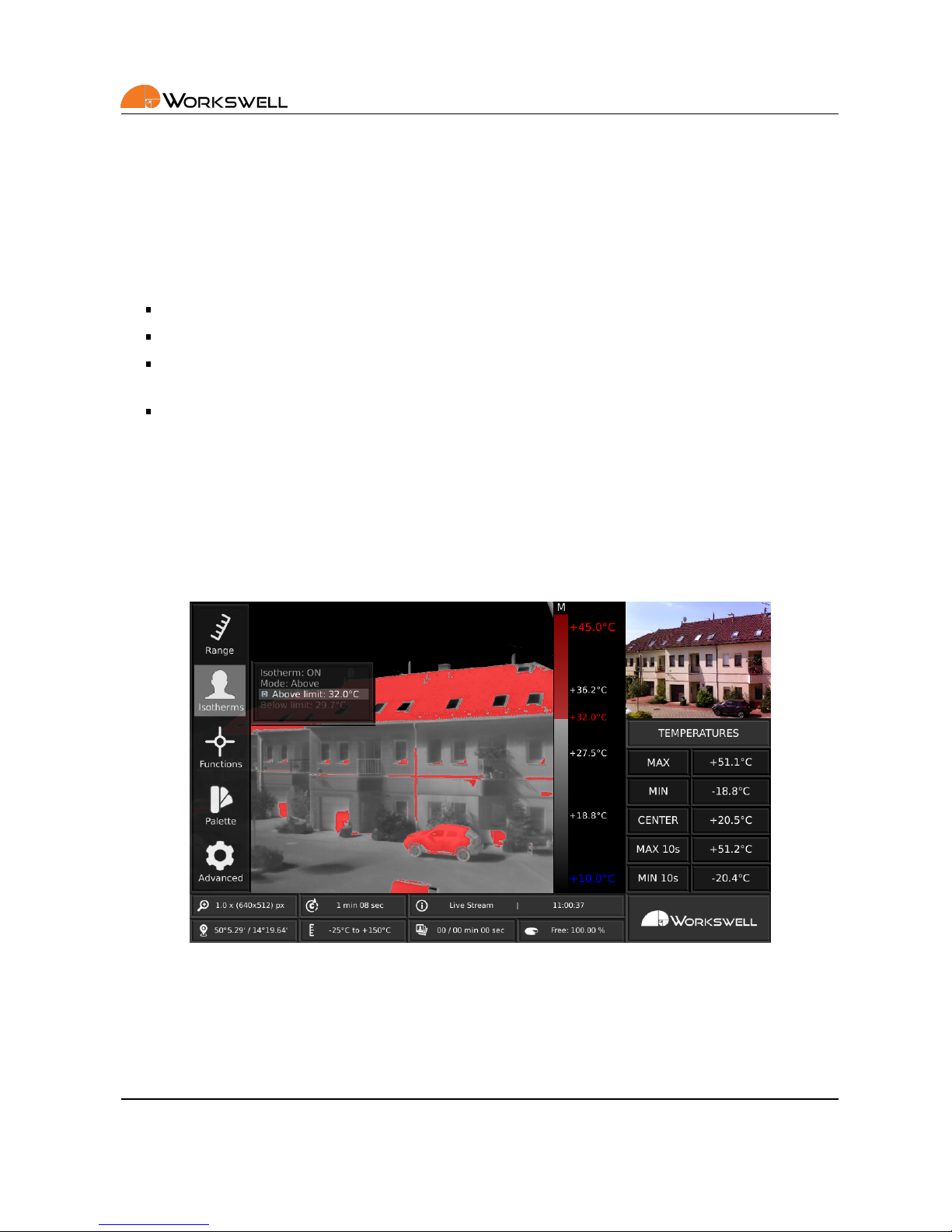
9.3 Isotherms
ISOTHERMS category allows user to select type of isotherm funcon (Below,Above, Between and Above & Below)
and also set the temperature limits.
ISOTHERMS menu consists of the following items:
ISOTHERM - ON or OFF
MODE - BELOW, ABOVE, BETWEEN or ABOVE & BELOW. Available only when Isotherm is set to ON.
ABOVE LIMIT - Above limit for mode ABOVE, BETWEEN and ABOVE & BELOW. Available only when one of
these modes is selected.
BELOW LIMIT - Below limit for mode BELOW, BETWEEN and ABOVE & BELOW. Available only when one of
these modes is selected
Note: When isotherms are turned on, the color palee is changed to grayscale palee by default. In order to
keep the color palee that was set by user, opon in Advanced menu is available.
Below is the descripon for each isotherms mode.
ABOVE mode marks all the areas that have higher temperature than ABOVE LIMIT set by user.
Figure 9.5 – Isotherms sengs – ABOVE.
BELOW mode marks all the areas that have lower temperature than BELOW LIMIT set by user.
E-mail and Web
support@workswell.eu
www.workswell.eu
Mobile:
+420 725 877 063
ID:
Reg. No.: 29048575
VAT No.: CZ29048575
Headquarters
Libocka 653/51b
Prague, Czech Republic
Revision 1.0 EN, 24thJan, 2017
All pictures are only for illustraon.
Real values may vary.
27

9. SYSTEM MENU (SETTINGS)
Figure 9.6 – Isotherms sengs – BELOW.
BETWEEN mode marks all the areas that have higher temperature than BELOW LIMIT and lower temperature
than ABOVE LIMIT.
Figure 9.7 – Isotherms sengs – BETWEEN.
ABOVE & BELOW mode marks all the areas that have higher temperaturethan ABOVE LIMIT or lower temperature
than BELOW LIMIT.
E-mail and Web
support@workswell.eu
www.workswell.eu
Mobile:
+420 725 877 063
ID:
Reg. No.: 29048575
VAT No.: CZ29048575
Headquarters
Libocka 653/51b
Prague, Czech Republic
Revision 1.0 EN, 24thJan, 2017
All pictures are only for illustraon.
Real values may vary.
28

9. SYSTEM MENU (SETTINGS)
Figure 9.8 – Isotherms sengs – ABOVE & BELOW.
The colors of marked areas can be set in Advanced menu. Default colors are red for Above mode, blue for Below
mode, green for Between mode and red and blue color for Above & Below mode.
The currently set isotherm limit is shown in the temperature legend. If the isotherm above limit is set higher
than the temperature maximum or the isotherm below limit is set lower than the temperature minimum, it is
indicated by the red or blue signs in the temperature legend.
Figure 9.9 – Isotherm sengs – limits exceed temperature range.
E-mail and Web
support@workswell.eu
www.workswell.eu
Mobile:
+420 725 877 063
ID:
Reg. No.: 29048575
VAT No.: CZ29048575
Headquarters
Libocka 653/51b
Prague, Czech Republic
Revision 1.0 EN, 24thJan, 2017
All pictures are only for illustraon.
Real values may vary.
29

9. SYSTEM MENU (SETTINGS)
9.4 Funcons
FUNCTIONS category allows user to capture images, record video, zoom camera that is currently in main camera
window, switch between infrared and visible spectrum camera and also use measurement funcons such as
maximum and minimum detecon (including crosses in image) and set the center spot temperature detecon.
Figure 9.10 – Funcons sengs.
FUNCTIONS menu consists of following items:
CAPTURE - Captures set of images that were specified in ADVANCED menu
RECORD - Starts and stops recording of radiometric video
ZOOM - Applies zoom to camera in MAIN CAMERA WINDOW
CHANGE MODE - Switches camera in MAIN CAMERA WINDOW
CROSS MAX, CROSS MIN, CROSS CENTER - Displays max, min or center cross in infrared camera image
DISPLAY TEMP - Displays temperatures of the crosses
E-mail and Web
support@workswell.eu
www.workswell.eu
Mobile:
+420 725 877 063
ID:
Reg. No.: 29048575
VAT No.: CZ29048575
Headquarters
Libocka 653/51b
Prague, Czech Republic
Revision 1.0 EN, 24thJan, 2017
All pictures are only for illustraon.
Real values may vary.
30

9. SYSTEM MENU (SETTINGS)
9.5 Palee
PALETTE category includes set of eighteen color palees that can be applied on the infrared image.
Figure 9.11 – Palee sengs.
E-mail and Web
support@workswell.eu
www.workswell.eu
Mobile:
+420 725 877 063
ID:
Reg. No.: 29048575
VAT No.: CZ29048575
Headquarters
Libocka 653/51b
Prague, Czech Republic
Revision 1.0 EN, 24thJan, 2017
All pictures are only for illustraon.
Real values may vary.
31

9. SYSTEM MENU (SETTINGS)
9.6 Advanced
ADVANCED category allows user to set advanced behavior of the applicaon. It is divided into nine more categories – MEASUREMENT, DISPLAY, SAVE IMAGES, ISOTHERMS, COMMUNICATION INTERFACE, MEMORY, SYSTEM, PLUGINS and INFO.
Figure 9.12 – Advanced sengs.
ADVANCED MENU consists of the following categories:
MEASUREMENT - Emissivity, Reflected temperature, Atmospheric temperature, Lens, Default values
DISPLAY - Temperature units, Language, Resoluon, Time to calibraon, Hold me, GPS info
SAVE IMAGES - Radiometric JPEG, Radiometric TIFF, Non-radiometric JPEG, Digital camera JPEG, Periodic
capture
ISOTHERMS - Palee, Above, Below and Between isotherm color, Isotherm intensity
COMMUNICATION INTERFACE - Digital IO Port 1 – 7 behavior, MAVLink power
MEMORY - Erase memory, Internal memory, Copy log files
SYSTEM - Current me and date, Erase memory, Default sengs, Reboot
PLUGINS - CWSI, MulMax, CAN, Ethernet
INFO
E-mail and Web
support@workswell.eu
www.workswell.eu
Mobile:
+420 725 877 063
ID:
Reg. No.: 29048575
VAT No.: CZ29048575
Headquarters
Libocka 653/51b
Prague, Czech Republic
Revision 1.0 EN, 24thJan, 2017
All pictures are only for illustraon.
Real values may vary.
32

9. SYSTEM MENU (SETTINGS)
9.6.1 Measurement
MEASUREMENT category contains sengs of measurement parameters such as emissivity, background and atmospheric temperature. You can also switch the calibraon tables for different lenses if you are using more
than one of them. In case of geng lost, there is also DEFAULT opon which sets the default measurement
parameters.
Figure 9.13 – Measurement menu.
MEASUREMENT menu consists of the following items:
EMISSIVITY - Emissivity of measured surface
REFL TEMP - Background temperature reflected by the scene
ATM TEMP - Temperature of the atmosphere
LENS - Select appropriate lens from the list aer physically changing your lens. This opon is available only
with mulple lenses.
DEFAULT - Sets default measurement parameters
9.6.2 Display
DISPLAY category contains sengs of what should be displayed on the screen. It allows user to choose temperature units, set the period of infrared camera calibraon and choose which GPS informaon will be available in
status bar. Also, four different resoluons and five languages can be set.
The nave resoluon of the WIRIS is 1024 x 600 so it is recommended to use when possible. In case that you have
set resoluon that is not supported by your monitor, press and hold the on/off buon for at least 10 seconds.
Aer than, WRIRS will reboot to the 1024x600 resoluon.
E-mail and Web
support@workswell.eu
www.workswell.eu
Mobile:
+420 725 877 063
ID:
Reg. No.: 29048575
VAT No.: CZ29048575
Headquarters
Libocka 653/51b
Prague, Czech Republic
Revision 1.0 EN, 24thJan, 2017
All pictures are only for illustraon.
Real values may vary.
33

9. SYSTEM MENU (SETTINGS)
The 720p resoluon is recommended to use with DJI Lightbridge, the 800 x 600 resoluon is recommended to
use with analogue Video converters. This resoluon also shows only one main camera without the addional
temperatures informaon. The system must reboot when changing the resoluon.
Figure 9.14 – Display menu.
Note: Do not unplug the power supply during the resoluon change.
DISPLAY MENU consists of following items:
UNITS - CELSIUS, FAHRENHEIT or KELVIN
LANGUAGES - ENGLISH, CZECH, FRENCH, GERMAN, SPANISH
RESOLUTION - 1280x720, 1024x768, 1024x600, 800x600
TIME TO CALIB - Period of infrared camera calibraon
HOLD TIME - Time for which the max and min temperature will be held
GPS INFO - POSITION, ALTITUDE, RELATIVE ALTITUDE, SATELLITES, SPEED
E-mail and Web
support@workswell.eu
www.workswell.eu
Mobile:
+420 725 877 063
ID:
Reg. No.: 29048575
VAT No.: CZ29048575
Headquarters
Libocka 653/51b
Prague, Czech Republic
Revision 1.0 EN, 24thJan, 2017
All pictures are only for illustraon.
Real values may vary.
34

9. SYSTEM MENU (SETTINGS)
9.6.3 Save Images
SAVE IMAGES category allows user to set which images will be saved, when CAPTURE funcon is acvated. It
also allows user to set periodic capturing. Also, the total me needed for saving selected images is shown.
Figure 9.15 – Save Images menu.
SAVE IMAGES menu consists of following items:
RADIOMETRIC RAW JPEG - Includes temperature data (Workswell CorePlayer compable)
RADIOMETRIC RAW TIFF - Includes temperature data (Pix4D, Agiso compable)
NON-RADIOMETRIC JPEG - Standard JPEG without temperature informaon
DIGITAL CAMERA - Standard JPEG from visible camera
PERIODIC CAPTURE - Captures selected images periodically with the interval set by user. Periodic capturing
begins when CAPTURE funcon is acvated and ends when CAPTURE funcons is acvated again.
E-mail and Web
support@workswell.eu
www.workswell.eu
Mobile:
+420 725 877 063
ID:
Reg. No.: 29048575
VAT No.: CZ29048575
Headquarters
Libocka 653/51b
Prague, Czech Republic
Revision 1.0 EN, 24thJan, 2017
All pictures are only for illustraon.
Real values may vary.
35

9. SYSTEM MENU (SETTINGS)
9.6.4 Isotherms
ISOTHERMS category contains isotherm palee sengs, isotherm colors sengs and also isotherm intensity
sengs.
Figure 9.16 – Isotherms menu.
ISOTHERM menu consists of the following items:
ISO PALETTE - GREY palee when isotherms acvated or NO CHANGE in palee
ISO ABOVE - Color of above isotherm
ISO BELOW - Color of below isotherm
ISO BETWEEN - Color of between isotherm
ISO INTENSITY - Opacity of isotherms
E-mail and Web
support@workswell.eu
www.workswell.eu
Mobile:
+420 725 877 063
ID:
Reg. No.: 29048575
VAT No.: CZ29048575
Headquarters
Libocka 653/51b
Prague, Czech Republic
Revision 1.0 EN, 24thJan, 2017
All pictures are only for illustraon.
Real values may vary.
36

9. SYSTEM MENU (SETTINGS)
9.6.5 Communicaon Interface
COMMUNICATION INTERFACE category allows user to set behavior of digital IO ports. For more informaon
about digital IO ports connecon please see the secon 7 Digital IO Ports.
Figure 9.17 – Communicaon Interface menu.
COMMUNICATION INTERFACE menu consists of the following items:
IO 1, IO 2 - Not available, fixed to menu control
IO 3 – IO 7 - Behavior of each digital input can be set independently
MAVLink 5V - Sets the +5V or 0V to the MAVLink power output pin
In the first step, PWM, TRIGGER or OUTPUT mode needs to be selected. For more informaon about PWM,
TRIGGER and OUTPUT mode please see the secon 7 Digital IO Ports.
E-mail and Web
support@workswell.eu
www.workswell.eu
Mobile:
+420 725 877 063
ID:
Reg. No.: 29048575
VAT No.: CZ29048575
Headquarters
Libocka 653/51b
Prague, Czech Republic
Revision 1.0 EN, 24thJan, 2017
All pictures are only for illustraon.
Real values may vary.
37

9. SYSTEM MENU (SETTINGS)
For each of the digital IO ports 3-7, you can select one of the following funcons:
PWM mode:
• Change mode - switch thermal or visible cameras shown in the main and preview windows.
• Capture - capture selected images
• Record - start/stop recording video
• Zoom - zoom camera shown in the main window
• Palee - change palee of the radiometric image
• Isotherm ON/OFF - toggle isotherm ON or OFF
• Man Range ON/OFF - toggle manual range ON or OFF
• Range Max - set the manual range maximum limit
• Range Min - set the manual range minimum limit
• Isotherm Above - set the isotherm above limit
• Isotherm Below - set the isotherm below limit
• Temperature Range - toggle the temperature range LOW/HIGH
• Hide Overlays - hide all crosses and signs shown in the main window
• Calibraon - do the thermal image calibraon
Trigger mode:
• Capture - capture selected images
• Record - start/stop recording video
• Calibraon - do the thermal image calibraon
Output mode:
• Capture Start - set output to +5V at the moment of capturing image for the me of 100ms
• Capture Finish - set output to +5V when all of the selected images are saved to the internal memory
of Flash Drive for the me of 100ms
• Calibraon - set output to +5V during the image calibraon
E-mail and Web
support@workswell.eu
www.workswell.eu
Mobile:
+420 725 877 063
ID:
Reg. No.: 29048575
VAT No.: CZ29048575
Headquarters
Libocka 653/51b
Prague, Czech Republic
Revision 1.0 EN, 24thJan, 2017
All pictures are only for illustraon.
Real values may vary.
38

9. SYSTEM MENU (SETTINGS)
9.6.6 Memory
MEMORY category allows user to erase memory, set internal memory as main storage an copy log files to flash
drive in case of facing any problems.
Figure 9.18 – Memory menu.
MEMORY menu consists of the following items:
ERASE MEMORY - Delete selected folders with images and recordings
INTERNAL MEMORY - Sets the internal memory as the main storage. (Available only when the external
Flash drive is set as the main storage)
COPY LOGS - Select ON to copy log files when connecng a flash drive
E-mail and Web
support@workswell.eu
www.workswell.eu
Mobile:
+420 725 877 063
ID:
Reg. No.: 29048575
VAT No.: CZ29048575
Headquarters
Libocka 653/51b
Prague, Czech Republic
Revision 1.0 EN, 24thJan, 2017
All pictures are only for illustraon.
Real values may vary.
39

9. SYSTEM MENU (SETTINGS)
9.6.7 System
SYSTEM category allows user to set the current me and date, set default sengs, reboot system and set start
system opon.
Figure 9.19 – System menu.
SYSTEM menu consists of the following items:
CURRENT TIME - Current me to be added to images and video
CURRENT DATE - Current date to be added to images and video
SET DEFAULT SETTINGS - Sets the system to factory default sengs
REBOOT SYSTEM - Reboots whole system for the fresh start
SYSTEM START - System can start by pressing the ON/OFF buon or immediately aer the power supply is
plugged in
E-mail and Web
support@workswell.eu
www.workswell.eu
Mobile:
+420 725 877 063
ID:
Reg. No.: 29048575
VAT No.: CZ29048575
Headquarters
Libocka 653/51b
Prague, Czech Republic
Revision 1.0 EN, 24thJan, 2017
All pictures are only for illustraon.
Real values may vary.
40

9. SYSTEM MENU (SETTINGS)
9.6.8 Plugins
PLUGINS category shows user all available plugins. When you click on the selected Plugin, you can see its descripon.
Figure 9.20 – Plugins menu.
PLUGINS menu consists of the following items:
CWSI - visualize the Crop (Crical) Water Stress Index and calculate real-me water stress values for precise
soil/crop agriculture evaluaon.
MulMax - special real-me mulple maximum evaluaon tool. The Max crosses automacally detect
local hotspot problems and show the crical pixels.
CAN - communicaon for DJI devices (A2, A3, etc.) for direct GPS metadata saving and camera control
funcons. Special internal HW module required.
Ethernet - TCP/IP communicaon for external camera control and image streaming capabilies. Special
internal HW module required.
For acvang any plugin, please follow the same procedure as with updang your system version, which is described in the 12 Firmware update secon.
E-mail and Web
support@workswell.eu
www.workswell.eu
Mobile:
+420 725 877 063
ID:
Reg. No.: 29048575
VAT No.: CZ29048575
Headquarters
Libocka 653/51b
Prague, Czech Republic
Revision 1.0 EN, 24thJan, 2017
All pictures are only for illustraon.
Real values may vary.
41

9. SYSTEM MENU (SETTINGS)
9.6.9 Info
INFO category displays informaon about system such as firmware version, device temperature and informaon
about Workswell s.r.o. company.
Figure 9.21 – Info menu.
E-mail and Web
support@workswell.eu
www.workswell.eu
Mobile:
+420 725 877 063
ID:
Reg. No.: 29048575
VAT No.: CZ29048575
Headquarters
Libocka 653/51b
Prague, Czech Republic
Revision 1.0 EN, 24thJan, 2017
All pictures are only for illustraon.
Real values may vary.
42

10. USB FLASH DRIVE MENU
10 USB flash drive menu
10.1 General Descripon
USB DRIVE MENU allows user to copy images and videos from internal memory to USB flash drive (supplied),
update firmware of the system, format USB flash drive and use USB flash drive as main storage memory. Once
the USB flash drive is connected, the USB FLASH DRIVE MENU appears.
Figure 10.1 – USB flash drive menu.
USB FLASH DRIVE MENU contains following items:
COPY - Copies selected images and videos from internal storage to connected USB flash drive.
MOVE - Moves selected images and videos from internal storage to connected USB flash drive. Moved
images and videos are available no more on internal storage.
UPDATE - Updates firmware of the system if update file is available on the connected USB flash drive.
FORMAT - Formats USB flash drive. All data on the drive will be lost.
MEMORY - Choose connected flash drive as main memory for storing images and videos.
Note: Due to slow data transfer speed of the USB 2.0 interface, lost of some frames in the radiometric
video can occur.
CANCEL - Return back to the applicaon.
E-mail and Web
support@workswell.eu
www.workswell.eu
Mobile:
+420 725 877 063
ID:
Reg. No.: 29048575
VAT No.: CZ29048575
Headquarters
Libocka 653/51b
Prague, Czech Republic
Revision 1.0 EN, 24thJan, 2017
All pictures are only for illustraon.
Real values may vary.
43

11. DATA TRANSFER
11 Data Transfer
11.1 General Descripon
Workswell WIRIS system is equipped with internal storage for captured images and recorded video. In order to
download these data from Workswell WIRIS system, supplied USB flash drive has to be connected to USB port
of Workswell WIRIS system. Once the USB flash drive is connected, the USB FLASH DRIVE MENU appears.
Figure 11.1 – USB flash drive menu.
We highly recommend using the supplied USB flash drive that is already formaed. In case of using other than
supplied USB flash drive, the user may be asked to format the drive. This can be done directly from USB FLASH
DRIVE menu by using FORMAT menu. Once the USB flash drive is formaed, the data can be transferred to it.
There are two ways of transferring the data to from the system internal storage to connected USB flash drive.
COPY - Copies selected images and videos from internal storage to connected USB flash drive. Files are not
deleted from internal storage.
MOVE - Moves selected images and videos from internal storage to connected USB flash drive. Moved
images and videos are no more available in internal storage.
Once the COPY or MOVE opon is selected, user is asked to choose which folders should be copied or moved.
Folder is created on every start of Workswell WIRIS system.
E-mail and Web
support@workswell.eu
www.workswell.eu
Mobile:
+420 725 877 063
ID:
Reg. No.: 29048575
VAT No.: CZ29048575
Headquarters
Libocka 653/51b
Prague, Czech Republic
Revision 1.0 EN, 24thJan, 2017
All pictures are only for illustraon.
Real values may vary.
44

11. DATA TRANSFER
Figure 11.2 – Folders to be copied.
The copy/move process starts when the user clicks COPY/MOVE SELECTED.
Warning: Do not unplug power supply or USB flash drive during copy/move process. The data lost may occur.
E-mail and Web
support@workswell.eu
www.workswell.eu
Mobile:
+420 725 877 063
ID:
Reg. No.: 29048575
VAT No.: CZ29048575
Headquarters
Libocka 653/51b
Prague, Czech Republic
Revision 1.0 EN, 24thJan, 2017
All pictures are only for illustraon.
Real values may vary.
45

12. FIRMWARE UPDATE
12 Firmware update
12.1 General Descripon
Workswell WIRIS system is supplied with the latest firmware. As me goes on, newer firmware will appear in
order to bring the user new funcons, improve the old ones or fixing bugs. For this purpose, the system allows
the user update the firmware using USB flash drive. The process of updang firmware consists of four steps.
1. Copy UPDATE KEY file to USB flash drive.
2. Upload UPDATE KEY file to hp://www.workswell.eu/firmware-update/.
3. Copy the generated update file to USB flash drive.
4. Update the system using USB flash drive with update file.
12.2 Update key copy
In order to copy update key to a USB flash drive, user has to select UPDATE opon in USB flash drive menu. If
there is no update file available, the update key is generated once the user confirms the UPDATE acon.
Figure 12.1 – Update menu – copy update key.
E-mail and Web
support@workswell.eu
www.workswell.eu
Mobile:
+420 725 877 063
ID:
Reg. No.: 29048575
VAT No.: CZ29048575
Headquarters
Libocka 653/51b
Prague, Czech Republic
Revision 1.0 EN, 24thJan, 2017
All pictures are only for illustraon.
Real values may vary.
46

12. FIRMWARE UPDATE
12.3 Update key upload
The user should upload the update key to the Workswell firmware update website within 24 hours. The update
file may not be generated if older update key is used.
Figure 12.2 – Update key upload – website form.
E-mail and Web
support@workswell.eu
www.workswell.eu
Mobile:
+420 725 877 063
ID:
Reg. No.: 29048575
VAT No.: CZ29048575
Headquarters
Libocka 653/51b
Prague, Czech Republic
Revision 1.0 EN, 24thJan, 2017
All pictures are only for illustraon.
Real values may vary.
47

12. FIRMWARE UPDATE
12.4 Firmware update process
If there is update file available on a USB flash drive, the user is offered to update the firmware. Firmware update
process will start when the user confirms the UPDATE acon and can take several minutes.
Figure 12.3 – Update menu – firmware update.
Warning: Do not turn off the system and do not unplug the power supply during the firmware update process.
Otherwise the damage to the system may occur.
E-mail and Web
support@workswell.eu
www.workswell.eu
Mobile:
+420 725 877 063
ID:
Reg. No.: 29048575
VAT No.: CZ29048575
Headquarters
Libocka 653/51b
Prague, Czech Republic
Revision 1.0 EN, 24thJan, 2017
All pictures are only for illustraon.
Real values may vary.
48

13. WORKSWELL COREPLAYER
13 Workswell CorePlayer
13.1 General Descripon
The Workswell WIRIS system can capture radiometric images and record radiometric video compable with
WorkswellCorePlayer (supplied with Workswell WIRIS system). Workswell CorePlayer offers the user many funcons for eding and processing radiometric images and videos.
Workswell CorePlayer is available at hp://www.workswell.eu/CorePlayer
Figure 13.1 – Workswell CorePlayer.
Workswell CorePlayer allows the user to
Change measurement parameters (emissivity, …)
Change temperature range, colour palee
Use mulple isotherms
Use measurement funcons in mulple ROIs (region of interest)
Export images
Export .avi video
Generate PDF reports
And much more…
E-mail and Web
support@workswell.eu
www.workswell.eu
Mobile:
+420 725 877 063
ID:
Reg. No.: 29048575
VAT No.: CZ29048575
Headquarters
Libocka 653/51b
Prague, Czech Republic
Revision 1.0 EN, 24thJan, 2017
All pictures are only for illustraon.
Real values may vary.
49

14. ENVIRONMENT CONDITIONS
14 Environment Condions
14.1 Environment Condions
You should follow these storage and operang condions for proper funcon of the Workswell WIRIS system:
Operaon temperature range from -15◦C to +50◦C
Storage temperature range from -30◦C to +60◦C
Humidity 5-95%, noncondensing
Maximum irradiance 100W/cm
2
If you use the product in conflict with these condions, damage to the Workswell WIRIS system can occur.
E-mail and Web
support@workswell.eu
www.workswell.eu
Mobile:
+420 725 877 063
ID:
Reg. No.: 29048575
VAT No.: CZ29048575
Headquarters
Libocka 653/51b
Prague, Czech Republic
Revision 1.0 EN, 24thJan, 2017
All pictures are only for illustraon.
Real values may vary.
50

15. INFRARED CAMERA BEHAVIOUR
15 Infrared camera behaviour
15.1 Infrared camera warm-up
Modern infrared cameras are based on a sensor (microbolometer array) that needs to be warmed-up to the
working temperature before it can be used. The sensor starts warming-up automacally when the user turns
Workswell WIRIS system on. The infrared camera is usually ready in less than 5 minutes.
During the warm-up process the accuracy of the measured temperature data is lower and various defects can
appear in the thermal image. Therefore, we recommend to let the infrared camera warm before using it.
15.2 Non-uniformity correcon
Infrared camera needs to be periodically calibrated in order to get reasonable measurement accuracy. This process is called Non-uniformity correcon (NUC) and is done automacally. The user can set calibraon period in
ADVANCED MENU → DISPLAY → TIME TO CALIB. Time to next calibraon is shown in STATUS BAR.
It is recommended to use shorter periods (2 – 5 minutes) during camera warm-up process and longer periods
(10 – 30 minutes) when the camera is already warmed-up.
Warning: Using only short periods (2 – 5 minutes) for a long me can cause early camera damage.
E-mail and Web
support@workswell.eu
www.workswell.eu
Mobile:
+420 725 877 063
ID:
Reg. No.: 29048575
VAT No.: CZ29048575
Headquarters
Libocka 653/51b
Prague, Czech Republic
Revision 1.0 EN, 24thJan, 2017
All pictures are only for illustraon.
Real values may vary.
51

16. MAINTANANCE
16 Maintanance
16.1 Cleaning the WIRIS head and cables
Liquids: Use one of these liquids:
Warm water
A weak detergent soluon
Equipment:
A so cloth
Procedure:
1. Soak the cloth in the liquid.
2. Twist the cloth to remove excess liquid.
3. Clean the part with the cloth.
16.2 Cleaning the infrared lens
Liquids: Use one of these liquids:
A commercial lens cleaning liquid with more than 30% isopropyl alcohol.
96% ethyl alcohol (C2H5OH)
DEE (= ”ether” = diethylether, C4H10O)
50% acetone (= dimethylketone, (CH3)2CO)) + 50% ethyl alcohol (by volume). This liquid prevents drying
marks on the lens.
Equipment:
Coon wool
Procedure:
1. Soak the coon wool in the liquid.
2. Twist the coon wool to remove excess liquid.
3. Clean the lens one me only and discard the coon wool.
Warning: Make sure that you read all applicable MSDS (Material Safety Data Sheets) and warning labels on
containers before you use a liquid: the liquids can be dangerous.
Cauon:
Be careful when you clean the infrared lens. The lens has a delicate an-reflecve coang.
Do not clean the infrared lens too vigorously. This can damage an-reflecve coang. Re-applying anreflecve coang is not possible and is required to change the lens.
E-mail and Web
support@workswell.eu
www.workswell.eu
Mobile:
+420 725 877 063
ID:
Reg. No.: 29048575
VAT No.: CZ29048575
Headquarters
Libocka 653/51b
Prague, Czech Republic
Revision 1.0 EN, 24thJan, 2017
All pictures are only for illustraon.
Real values may vary.
52

17. TROUBLESHOOT
17 Troubleshoot
17.1 Turning ON
When the ON/OFF buon is pressed in order to start the WIRIS and nothing happens, please check you power
supply. A stable power supply is essenal for correct WIRIS behavior.
17.2 Safe mode
When the camera internal firmware does not terminate regularly three mes in a row, the WIRIS boots into the
Safe mode. In this case, please contact the Workswell support center support@workswell.eu and report the
issue.
Figure 17.1 – Safe mode.
In the Safe mode, you can choose several opons:
Reboot and connue with standard applicaon
• Choose this opon when first observing the safe mode.
Copy log files to connected flash drive
• Choose this opon to copy log files for faster solving of the issue.
• Please, send these log files to Workswell support center with informaon about the issue.
Restore to Factory defaults
E-mail and Web
support@workswell.eu
www.workswell.eu
Mobile:
+420 725 877 063
ID:
Reg. No.: 29048575
VAT No.: CZ29048575
Headquarters
Libocka 653/51b
Prague, Czech Republic
Revision 1.0 EN, 24thJan, 2017
All pictures are only for illustraon.
Real values may vary.
53

17. TROUBLESHOOT
• Choose this opon to restore the system to its Factory defaults. All of the applied updates will be
removed.
• A stable power supply has to be maintained during the Factory Default!
17.3 Black screen
When the WIRIS resoluon is changed, the WIRIS reboots and starts with the new one. If you see only a
black screen, it is possible that your monitor does not support this new resoluon. For restoring the default
1024x600px resoluon, press and hold the on/off buon for at least 10 seconds. Aer that, WIRIS will reboot to
its default resoluon. Please, check your monitor’s supported resoluons before changing the WIRIS resoluon.
17.4 Remote control
When selecng the TRIGGER mode for a digital input, make sure that the selected input is not connected to your
remote controller with PWM output. Otherwise, the TRIGGER input will not behave as expected.
17.5 System Update
Makesure that your WIRIS version is up to date. Youcan find informaon about the current version on hp://www.dronethermal-camera.com/firmware-update/
E-mail and Web
support@workswell.eu
www.workswell.eu
Mobile:
+420 725 877 063
ID:
Reg. No.: 29048575
VAT No.: CZ29048575
Headquarters
Libocka 653/51b
Prague, Czech Republic
Revision 1.0 EN, 24thJan, 2017
All pictures are only for illustraon.
Real values may vary.
54

Contacts
Sales Department
Adam Švestka, MSc., MBA
Mobile: +420 725 955 464
E-mail: adam.svestka@workswell.cz
Headquarters
Libocka 653/51b
160 00, Prague6
Czech Republic
Branches
Meziricska 100
756 61, Roznov p. R.
Czech Republic
Company contact details
Mobile: +420 725 877 063
E-mail: info@workswell.eu
Web: www.drone-thermal-camera.com
Univerzitni 1
010 08, Zilina
Slovak Republic
 Loading...