

Page 1
CAUTION
OWNER’S
. to improve its products
where it is possible and
. reserves the right to make
changes or improvements in
design and construction at any
time without incurring the
obligation to make these
changes on previously
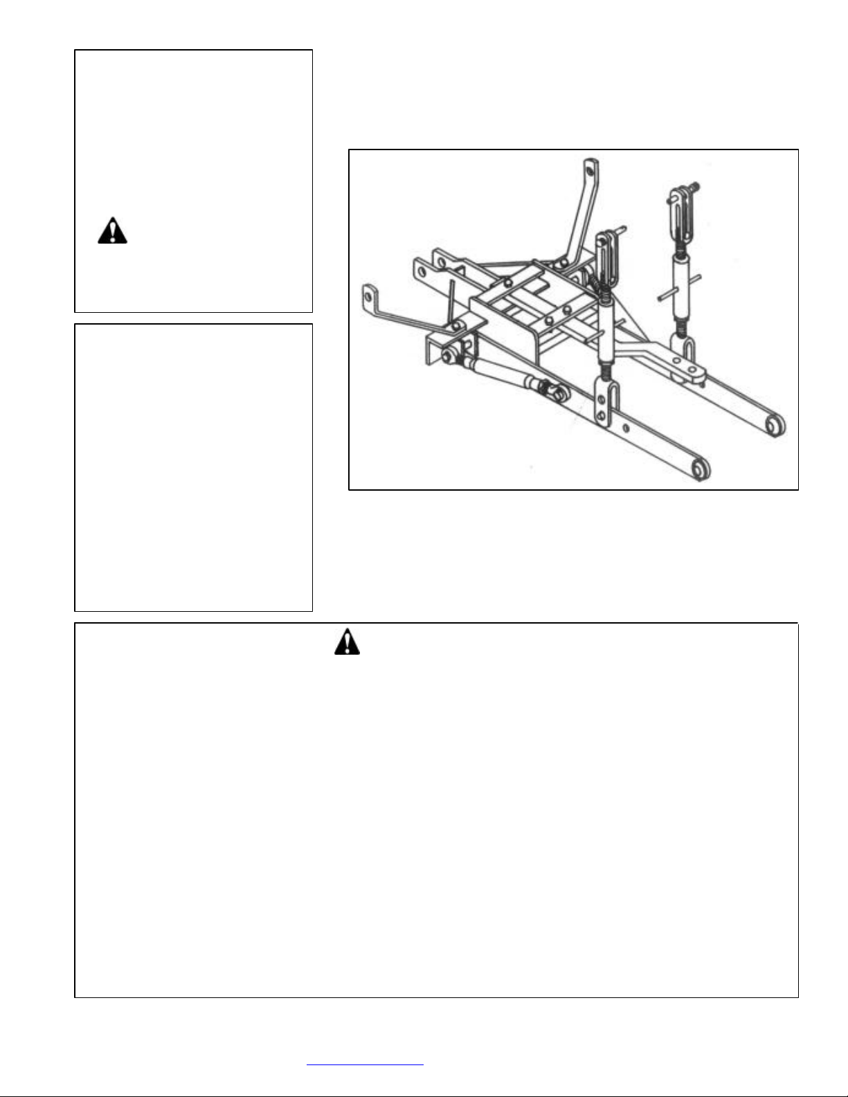
3 PT. HITCH ADAPTER KIT
1. Select an area for assembly that is clean and free
of any debris, which might cause persons
Do not lift heavy parts or assemblies. Use crane,
jack, tackle, fork trucks or other mechanical
Preview the assembly instructions in your
If the assembly instructions call for parts or
assemblies to be blocked up, use only blocking
material that is in good condition and is capable
of handling the weight of the assembly to be
blocked. Also insure that the blocking material is
Never put hands, or any other part of body under
blocked up assemblies if at all possible.
6. After completing assembly, thoroughly inspect
the machine to be sure that all nuts, bolts,
hydraulic fittings or any other fastened
Before operating the machine, thoroughly read
the operation section of your operator’s
Before operation, read the maintenance section
of your operator’s manual to be sure that any
as gearboxes
Before operating equipment. If you have
any questions regarding the proper
assembly or operation, contact your
WORKSAVER, INC.
MANUAL
Packing
Assembly & Mounting
Operating Instructions
MODEL NO.
HK-307
CAUTION
For Operation
Read Rules And
Instructions Carefully
STATEMENT
OF POLICY
It is the policy of Worksaver,
Inc
practical to do so. Worksaver,
Inc
Maintenance
Repair Parts
manufactured units.
THE FOLLOWING SAFETY PRECAUTIONS SHOULD BE THOROUGHLY UNDERSTOOD
BEFORE ATTEMPTING TO BEGIN ASSEMBLING THIS MACHINE .
working on the assembly to trip.
2.
devices.
3.
operator’s manual before proc eeding further.
4.
on a clean, dry surface.
5.
P.O BOX 100, LITCHFIELD, IL. 62056-100
Phone: 217-324-5973 Fax: 217-324-3356
E -Mail: [email protected] Web Site: www.worksaver.com
HK-307
For Allis-Chalmers
Model CA Tractors
assemblies have been thoroughly tightened.
7.
manual.
8.
parts requiring lubrication such
are full to avoid any possible damage.
9.
Worksaver dealer or representative.
Page 2

To the Owner/Operator/Dealer
All implements with moving parts are potentially hazardous. There is no substitute for a cautious, safe-
minded operator who
facturer has designed this implement to be used
Instructions
The Model HK-307 hitch adapter kit is designed for
This kit uses the existing hydraulic lift on the tractor
pped in knocked down condition
so as to command the lowest freight rates. Shipment
Before installing the adapter kit, it is necessary to
Check the threaded holes that go into the tractor
housing and make sure the threads are in good condition
es are
Be sure tires and rims are in good condition. Inflate
Check the tractor’s hydraulic system. Refer to your
for any adjustments
necessary to put the hydraulic system in good working
order. (I&T shop manuals will list most specifications
available from most farm
e sure
it is in good condition and bolted securely to the tractor.
Purchase a new shield if old shield is damaged or
missing. (You may have to use a tractor salvage yard for
ver Protection
Structure) be installed on all tractors. Contact your local
In order to mount this kit, it will first be necessary to
remove the swinging drawbar and mounting brackets
1/2” draw pin,
attach the main frame to support arm on the underside of
Slide the mainframe braces over the outside pins
n
on the parts drawing and capture them with the hairpins
frame braces. Tighten these bolts securely.
Pin the pivoting ends of the lift arm leveling
th the 5/8” top
hand ends
of the hitch main frame, start the ends of the pull pins
(Ref. #5) through the outer pull bracket ears. Position
hole goes to the
As soon as the end of the pull pin passes through the
first outer pull bracket ear, slide the pull pin spacer
(Ref #6) on the pin so that it is located between the first
and second pull bracket ears. Slide the pull pin in
further until the end is just entering the second pull
Then place the forward end of the lift arm between
the large side plate on the main hitch frame and the
second pull bracket. Slide the pull pin in further so that
ball end of the lift arm and enters
Rotate the pull pin so that the holes in the pin are
horizontal. Slide the spacer tube and adjust the pull pin
so that a large (5/16”) hairpin clip can be inserted
ter hole of the pull pin. This locks the
Raise the lift arms, sliding them between the clevis
ends of the lift arm leveling assemblies, and pin them
Install the stabilizer stub pins (Ref #19) in the
ard holes of each lift arm. Have the large (7/8”)
diameter of the stub pin to the outside of the lift arm
Do not use a lock
. Place a screwdriver or small
the nut on the
Place one end of the stabilizer bars (Ref #17) over
the ends of the pull pins on the outer ends of the frame
The stabilizer bars have threaded ends and can be
urning the center
barrel. Adjust the stabilizer bars, then slide the other
end over the stabilizer stub pins in the lift arms. Secure
When connection the hitch to an implement, it
end of the
stabilizer bar from the lift arm. This allows the lift arm
Continued on page 2
recognizes the potential hazards and follows reasonable safety practices. The manu
with all its safety equipment properly attached, to minimize the chance of accidents.
BEFORE YOU START!! Read the safety messages on the implement and shown in your manual. Observe the rules of safety
the Allis Chalmers Model CA tractors.
to raise and lower the 3-pt. Hitch.
PACKING
The adapter kit is shi
consists of 1 cartons and 1 frame assembly.
TRACTOR PREPARATION
remove the existing swinging drawbar assembly.
and that the holes are clean.
CAUTION! If an air hose is used to blow any
loose rust or dirt from the holes, be sure safety glass
used to prevent particles from entering an eye.
tires to the proper recommended air pressure.
tractor operator’s manual or dealer
and adjustment instructions –
equipment dealers.)
Check the shield over the PTO stub shaft. Mak
replacement parts on older tractors.)
It is recommended that a ROPS (Roll-O
and common sense!
assemblies to the tractor lift brackets wi
link pins and linchpins provided.
On both the outer left-hand and the right-
the pull pin so that the end with NO
inside.
bracket ear.
it goes through the
the hole in the large side plate.
through the cen
pull pin in place on each side.
in place.
forw
and the threaded nut to the inside.
washer under the nut
bar through the linchpin hole and tighten
stub pin.
dealer for a ROPS for your tractor.
ASSEMBLY
from your tractor. Using the 7/8” x 6-
the tractor and secure it with the hairclip pin provided.
mounted in the rear axle housings in the position show
provided. Pivot the rear of the main frame to the main
and secure with linchpins.
adjusted to the correct length by t
in place with linchpins.
NOTE:
will be necessary to remove the lift arm
to swing out and be installed on the pull pin of the
Page 3

Instructions (Continued from page 1)
the stabilizer bars need to be reconnected and adjusted
op link bracket from the top link and
attach the top link to the top link bracket, and
tighten the bolt securely. Place the top link clamps,
one on each side of the top link bracket and tighten
NOTE: The top link should be placed at the
Two (2) holes are provided on the lift arms to
the greatest lifting
range for the ball ends of the lift arms. The rear holes
The adjustable screw type leveling assemblies will
provide additional adjustment in the lifting height of
1/4” OF THREAD ON EACH END IS ENGAGED
INTO THE THREADED BARREL OF THE
The adjustable screw type top link can also be
shortened or lengthened to adapt different implements
ous degrees of pitch on
way ball sockets on the end of the lift arms
will allow you to connect to either Category I or
Category II implements. If the drawbar or implement
, then make
sure the balls are turned so that the 7/8” dia., holes are
1/8” dia., holes
are used with the smaller 7/8” dia., pins, the
ball holes will wear rapidly in an uneven
pattern and make the entire ball socket
The stabilizer bars should be used whenever
possible, as they provide rigidity and stability to the
plus added strength. The stabilizer bars have
threaded stubs so their length can be adjusted so the
be increased or decreased to
accommodate the different width of Category I and
This kit is designed to lift up to 1600 lbs., but, of
course, lifting capacity is dependent on the pressure
tem. You
will also find that the closer the load is kept to the
Be sure your tractor is in good
condition and properly equipped with counterweights.
sure all
tractor operators are familiar with the safety rules of
pt. hitch rear
blade in a reverse position (bulldozing), use extra care.
DO NOT RAM BLADE into dirt or packed snow
ft arms and the blade are not built to
take high impact loads in this position. RAMMING
backwards can also dislodge operator from seat and/or
tractor controls, resulting in possible serious injury or
may be
necessary to reposition and take less “bite” on the
Watch for and avoid hidden obstructions, i.e.,
buried pipes, rocks, concrete piers, uneven concrete
slabs, stumps, etc., when operation. This is especially
ü Keep children away from danger all day,
safety and that of your family and fellow
citizens.
implement.
After the lift arms are connected to the implement,
so that the implement is centered behind the tractor.
Remove the t
place it around the rocker shaft of the tractor.
Re-
them securely.
approximate center of the tractor rocker shaft.
OPERATION
connect to the lower ends of the leveling assemblies.
The forward holes will provide
will allow heavier loads to be handled by the hitch.
the hitch. NOTE: BE SURE THAT AT LEAST 1-
LEVELING ASSEMBLIES.
and can be used to obtain vari
the implements you are using.
The 2-
you mount has Category I (7/8” dia.) pins
used.
IMPORTANT: If the larger 1-
unit –
spread of the lift arms can
Category II tools.
eventu ally unusable.
and condition of the tractors hydraulic sys
tractor, the more you will be able to lift.
CAUTION!
Read all the safety precautions and make
tractor operation.
CAUTION! When using a 3-
piles! Tractor li
death.
Always ease the tractor into the load. It
material to move it safely.
of concern when removing snow.
MAINTENANCE
Check all bolts and nuts to be sure they are tight.
Periodically oil the following:
a. Top link (upper 3rd link) threads
b. Cylinder pins
c. Ball sockets
d. Leveling assembly threads
e. Stabilizer bar threads
every day.
ü Equip tractors with rollover protection
(ROPS) and keep all machinery guards
in place.
ü Please work, drive, play, and live each
day with care and concern for your
Page 2
Page 4
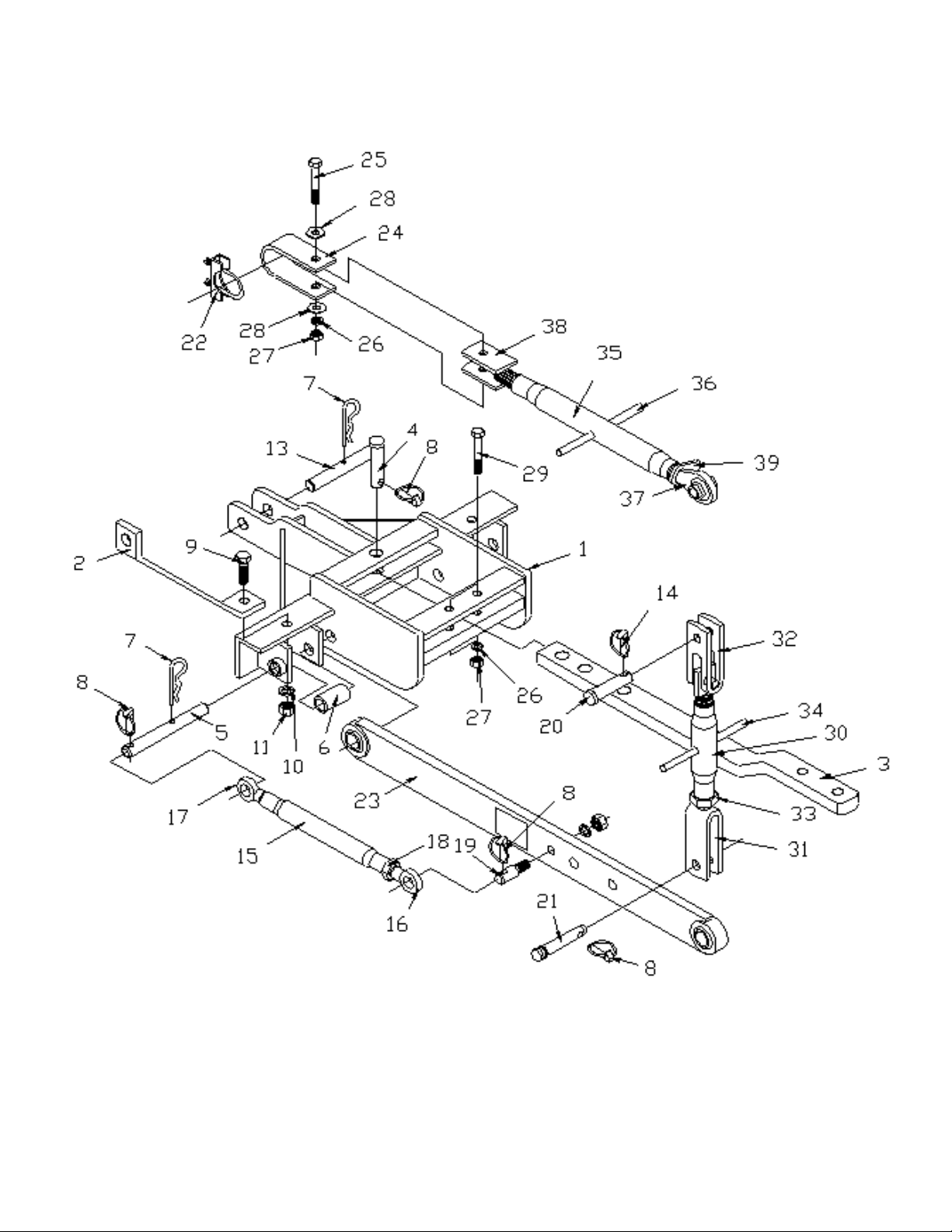
EXPLODED PARTS VIEW OF
FOR HK-307
Obey All
Safety Warnings
Page 3
Page 5

REPAIR PARTS FOR
2
862610
Main Frame Mount
2
3
590038
Swinging Drawbar (AK-67)
14860107
Upper Lift Pin
1
6
865339
Pin Lock Tube
27590014
Hair Clip Pin (AK-36)
38590006
Linch Pin, 7/16" (AK-14)
7
10
2502007
Washer, 5/8" Spring Lock
2112500013
Nut, 5/8"-11 NC Full Hex
212590097
Hair Clip Pin, (SC-175)
2
14
590034
Linch Pin. 1/4" (AK-61)
2
590317
Stabilizer Assembly (Parts 15-18)
215590406
Barrel, 7/8"-14NF
2
16
590407
Stabilizer End, RH
2
17
590318
Stabilizer End, LH
2182500018
Nut, 7/8"-14NF Jam Hex
2
20
590121
Top Link Pin, Cat. 0 (AK-800)
2
21
590001
Top Link Pin, Cat. I (AK-8)
2222504115
Top Link Clamp, (1-3/4" Std. Muffler Clamp)
2
24
860106
Top Link Clamp
1252503012
Bolt, 1/2"-13NC x 3" Hex Head
1262502002
Washer, 1/2" Spring Lock
3
28
2501003
Wahser, 1/2" Flat
2292503109
Bolt, 1/2"-13NC x 3-1/2" Hex Head
2
590074
Adjustable Lift Arm Leveling Assembly (Parts 30-34)
2
31
861136
Lower Lift Bracket
232590008
Upper Lift Bracket
2332500024
Nut, 1-1/8"-7NC Jam Hex
2
34
590145
Knock-In Handle
2
862616
Top Link Cat. I Complete (Parts 35-39)
135590116
Barrel, Top Link
1
37
590004
Top Link Repair End (AK-12F)
1
38
862618
Top Link End
139590128
Top Link Barrel Lock
1
N/S
101082
Safety Sign - Warning (Pull from Drawbar)
1
HK-307
3-PT. Hitch Adapter Kit
Ref. No Part No. Description
1 865302 Main Frame Weldment 1
5 865338 Pull Bracket Pin 2
9 2503048 Bolt, 5/8"-11NC x 2" Hex Head 2
13 862611 Rear Drawpin 1
19 590069 Stabilizer Stub Pin, (AK-378) 2
No.
Req'd
23 865014 Lift Arm Weldment 2
27 2500003 Nut, 1/2"-13NC Full Hex 3
30 590278 Leveling Barrel (1-7/8"-7NC) Swaged 2
36 590145 Knock-In Handle 1
N/S 101039 Safety Sign - Caution (Stay Clear of Arms) 2
Page 4
Page 6
SAFETY PRECAUTIONS
• Machinery should be operated only by those
Stop the engine, lower all equipment, lock the
key before
Never stand between tractor and implement
Loose fitting clothing should not be worn, to
Detach implement in area where children
When performing adjustments or maintenance
on an implement, first lower it to the ground or
Only a qualified operator should be permitted
e is in the clear before
starting tractor or raising or lowering
Operate the tractor and implement only while
Reduce speed when transporting mounted
implement to avoid bouncing and momentary
• A heavy load can cause instability of the
tractor. Use extreme care during road travel.
Slow down on turns and watch out for bumps.
weights to
ves so there is
Avoid driving too close to the edge of ditches
Do not transport implement on public toads
without reflectors and slow moving vehicle
emblem in daylight and with approved
iods of
Due to the width of some implements, use
extra caution on highways, farm roads, and
Always be sure the implement is in the proper
Keep alert and watch the front as well as the
OWNER’S
WORKSAVER LIMITED WARRANTY
warrants its implements, parts and accessories to be free from defects in
materials and workmanship for a period of six (6) months from the date of purchase. Upon
will repair or exchange without charge any part, which upon
This does not apply to (1) parts that have worn out in normal use, (2) parts broken because
mproper assembly or operation by the customer, (3) parts accidentally damaged, (4) failure
of parts traceable to improper care, (5) parts failing through use of implement for purposes
and the limitations expressed herein are in lieu of
WORKSAVER, INC
Please work, play, and live each day with care and
your family and
MOST ACCIDENTS OCCUR BECAUSE OF NEGLECT OR CARELESSNESS, AVOID NEEDLESS
ACCIDENTS BY FOLLOWING ALL OF THE SAFETY PRECAUTIONS LISTED BELOW.
who are responsible and are authorized to do so.
•
brakes, and remove the ignition
dismounting from the tractor.
•
while tractor is being backed to hitch.
•
avoid catching on various parts.
•
normally do not play.
•
block it securely at a workable height.
•
on tractor when in operation; no riders allowed.
• Make certain everyon
equipment.
•
seated in the driver’s seat.
•
Tractor may need front countercounter-balance the weight of the implement.
• Reduce speed on hillsides or cur
no danger of tipping.
•
or creeks.
•
warning lights at night and other per
poor visibility.
•
when approaching gates.
•
position for transport.
•
rear when working with the implement.
loss of steering control.
concern for your safety and that of
MANUAL
MODEL NO.
HK-307
WHEN ORDERING
REPAIR PARTS, ALWAYS
GIVE THE FOLLOWING
INFORMATION:
1. PART NUMBER
2. PART DESCRIPTION
3. MODEL NUMBER
4. NAME OF ITEM
MARCH 2001
fellow citizens.
3 PT. HITCH ADAPTER KIT
HK-307 – For A.C. Model CA Tractors
Worksaver
written approval, Worksaver
examination by Worksaver or its authorized agent, shall disclose to be defective.
of i
other than those for which it was designed.
The obligations assumed by Worksaver
all other warranties expressed or implied.
P.O. BOX 100, LITCHFIELD, IL. 62056-0100
Web Site: www.worksaver.com E-Mail: [email protected]
Phone: 1-217-324-5973 Fax: 1-217-324-3356
.
 Loading...