

Worksaver HK-305 User Manual
CAUTION
OWNER’S
. to improve its products
where it is possible and
. reserves the right to make
changes or improvements in
design and construction at any
time without incurring the
obligation to make these
changes on previously
3 PT. HITCH ADAPTER KIT
1. Select an area for assembly that is clean and free
of any debris, which might cause persons
Do not lift heavy parts or assemblies. Use crane,
jack, tackle, fork trucks or other mechanical
Preview the assembly instructions in your
If the assembly instructions call for parts or
assemblies to be blocked up, use only blocking
material that is in good condition and is capable
of handling the weight of the assembly to be
blocked. Also insure that the blocking material is
Never put hands, or any other part of body under
blocked up assemblies if at all possible.
6. After completing assembly, thoroughly inspect
the machine to be sure that all nuts, bolts,
hydraulic fittings or any other fastened
Before operating the machine, thoroughly read
the operation section of your operator’s
Before operation, read the maintenance section
of your operator’s manual to be sure that any
s gearboxes
Before operating equipment. If you have
any questions regarding the proper
assembly or operation, contact your
WORKSAVER, INC.
MANUAL
Packing
Assembly & Mounting
Operating Instructions
MODEL NO.
HK-305
CAUTION
For Operation
Read Rules And
Instructions Carefully
STATEMENT
OF POLICY
It is the policy of Worksaver,
Inc
practical to do so. Worksaver,
Inc
Maintenance
Repair Parts
manufactured units.
THE FOLLOWING SAFETY PRECAUTIONS SHOULD BE THOROUGHLY UNDERSTOOD
BEFORE ATTEMPTING TO BEGIN ASSEMBLING THIS MACHINE .
working on the assembly to trip.
2.
devices.
3.
operator’s manual before proceeding further.
4.
on a clean, dry surface.
5.
P.O BOX 100, LITCHFIELD, IL. 62056-100
Phone: 217-324-5973 Fax: 217-324-3356
E -Mail: sales@worksaver.com Web Site: www.worksaver.com
HK-305
For A.C. Models
WD & WD45 Tractors
assemblies have been thoroughly tightened.
7.
manual.
8.
parts requiring lubrication such a
are full to avoid any possible damage.
9.
Worksaver dealer or representative.

To the Owner/Operator/Dealer
All implements with moving parts are potentially hazardous. There is no substitute for a cautious, safe-
minded operator who
facturer has designed this implement to be used
Instructions
The Model HK-305 hitch adapter kit is designed for
This kit uses the existing hydraulic lift on the tractor
it is shipped in knocked down condition
so as to command the lowest freight rates. Shipment
Before installing the adapter kit, it is necessary to
he threaded holes that go into the tractor
housing and make sure the threads are in good condition
Be sure tires and rims are in good condition. Inflate
Check the tractor’s hydraulic system. Refer to your
stments
necessary to put the hydraulic system in good working
order. (I&T shop manuals will list most specifications
available from most farm
Check the shield over the PTO stub shaft. Make sure
in good condition and bolted securely to the tractor.
Purchase a new shield if old shield is damaged or
missing. (You may have to use a tractor salvage yard for
on
Structure) be installed on all tractors. Contact your local
In order to mount this kit, it will first be necessary to
remove the swinging drawbar and mounting brackets
x 2 hex head bolts,
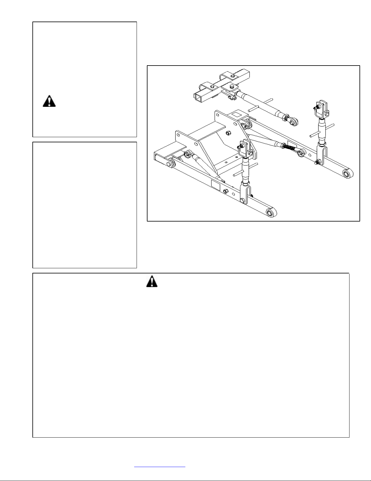
attach the main frame of the kit to the swinging drawbar
mount. (NOTE: Use the two holes in the swinging
drawbar mount that are parallel.) Tighten these bolts
lift arm-leveling assemblies into the snap couplers, and
hand ends
of the hitch main frame, start the ends of the pull pins
(ref. #5) through the outer pull bracket ears. Position
hole goes to the
As soon as the end of the pull pin passes through the
first outer pull bracket ear, slide the pull pin spacer (ref
#6) on the pin so that it is located between the first and
rs. Slide the pull pin in further
until the end is just entering the second pull bracket
Then place the forward end of the lift arm between
the large side plate on the main hitch frame and the
so that
it goes through the ball end of the lift arm and enters
Rotate the pull pin so that the holes in the pin are
horizontal. Slide the spacer tube and adjust the pull pin
be inserted
through the center hole of the pull pin. This locks the
Raise the lift arms, sliding them between the clevis
ends of the lift arm leveling assemblies, and pin them
pins (ref #34) in the
forward holes of each lift arm. Have the large (7/8”)
diameter of the stub pin to the outside of the lift arm
Do not use a lock
. Place a screwdriver or small
linchpin hole and tighten the nut on the
Place one end of the stabilizer bars (ref #21) over
the ends of the pull pins on the outer ends of the frame
The stabilizer bars have threaded ends and can be
to the correct length by turning the center
barrel. Adjust the stabilizer bars, then slide the other
end over the stabilizer stub pins in the lift arms. Secure
When connection the hitch to an implement, it
ary to remove the lift arm end of the
stabilizer bar from the lift arm. This allows the lift arm
to swing out and be installed on the pull pin of the
Continued on page 2
Page 1
recognizes the potential hazards and follows reasonable safety practices. The manu
with all its safety equipment properly attached, to minimize the chance of accidents.
BEFORE YOU START!! Read the safety messages on the implement and shown in your manual. Observe the rules of safety
the Allis Chalmers Model WD and WD45 tractors.
to raise and lower the 3-pt. Hitch.
PACKING
The adapter k
and common sense!
then snap them back down.
On both the outer left-hand and the right-
the pull pin so that the end with NO
inside.
consists of 3 cartons.
TRACTOR PREPARATION
remove the existing swinging drawbar assembly.
Check t
and that the holes are clean.
CAUTION! If an air hose is used to blow
any loose rust or dirt from the holes, be sure safety
glasses are used to prevent particles from entering an eye.
tires to the proper recommended air pressure.
tractor operator’s manual or dealer for any adju
and adjustment instructions –
equipment dealers.)
it is
replacement parts on older tractors.)
It is recommended that a ROPS (Roll-Over Protecti
dealer for a ROPS for your tractor.
ASSEMBLY
from your tractor. Using the ¾”
securely.
Open the snap couplers on your tractor, and place the
second pull bracket ea
ear.
second pull bracket. Slide the pull pin in further
the hole in the large side plate.
so that a large (5/16”) hairpin clip can
pull pin in place on each side.
in place.
Install the stabilizer stub
and the threaded nut to the inside.
washer under the nut
bar through the
stub pin.
and secure with linchpins.
adjusted
in place with linchpins.
NOTE:
will be necess
implement.
After the lift arms are connected to the implement,
 Loading...