

Page 1
WillowTM Dual-Wide Assembly Instructions
M4 8mm Screw M4 12mm Screw
M4 16mm Screw Spacer
M4 8mm Screw M4 12mm Screw
M4 16mm Screw Spacer
Important Safety Instructions
Read and understand all these safety instructions before using the product.
Do not mount the Desk Base of the Willow Arm on an unstable surface or any surface that could not mount the Desk
Base rmly.
During installation, beware of the recoil of the Willow Arm body when attaching or detaching the monitor to the Willow
Arm. To prevent damage or injury when changing the monitor, always raise the Arm to its highest position before the
monitor is detached. The Willow Arm can support monitors from 1 to 14 pounds.
Do not attempt to disassemble, service or modify the product.
Use only a slightly damp cloth to clean the Willow Arm surface. Never use ammable solvents like alcohol, benzene,
thinner, etc. on the product.
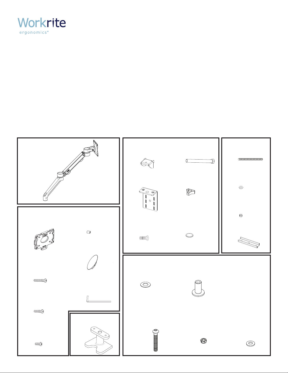
Parts grouped by carton
Willow Arm Assembly
A
Qty: 2
Quick Release
B
Bracket
Qty: 2
M4x18 Phillips
C
Screws
Qty: 8
M4x12 Phillips
D
Screws
Qty: 8
M4x8 Phillips
E
Screws
Qty: 8
10mm Plastic
F
Spacers
Qty: 8
Pivot Cover Cap
G
Qty: 2
3/16" Allen
H
Wrench
Qty: 1
Desk Base
I
Qty: 1
Upper Clamp
J
Bracket
Qty: 1
Lower Clamp
K
Bracket
Qty: 1
¼" x 20 x ⅜"
L
Phillip Flat
Head Screws
Qty: 2
Plastic
T
Pivot
Washer
Qty: 2
⅜"x16x2½" Button
V
Head Allen Cap
Screw
Qty: 2
⅜" x 16 x 3½"
M
Hex Bolt
Qty: 1
Plastic
N
Clamp Knob
Qty: 1
Plastic
O
Clamp Pad
Qty: 1
Flange
U
W
OR
Pin
Qty: 2
⅜"x16
Lock Nut
Qty: 2
WA2000-G-S only WA2000-C-S only
⅜” x 16 x 4½"
P
Threaded Stud
Qty: 1
⅜" Steel
Q
Washer
Qty: 1
⅜" x 16
R
Hex Nut
Qty: 1
U-Bracket
S
Qty: 1
⅜" ID
X
Belleville
Spring
Washer
Qty: 2
#1500181 - Rev A
Page 2
Verify that you have all the hardware and tools needed for the assembly
Check your packages against the parts list
on page 1 to verify that you have all the
parts needed.
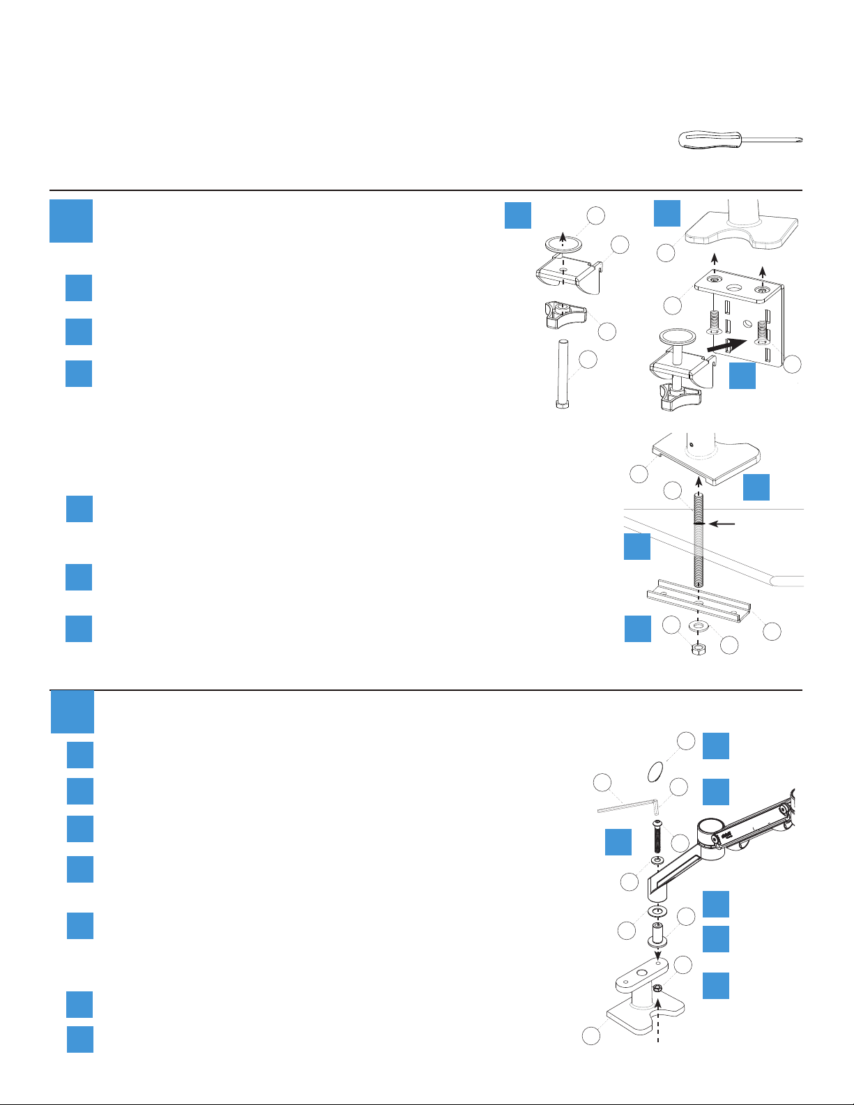
Assemble Base
You will also need the following tools:
#3 tip Phillips screwdriver
1
Clamp Mount: WA2000-C-S only
Assemble Clamp - Thread Hex Bolt (M) through Knob (N)
and Upper Clamp Bracket (J) and tighten securely. Press
a
the Plastic Clamp Pad (O) onto the end of the Bolt.
Mount Lower Clamp Bracket (K) to Desk Base with
b
Screws (L) and tighten using a #3 Phillips Screw Driver.
Put Desk Base (I) onto work surface then slide teeth of
c
Clamp into Bracket slots. Use the highest slots possible
for best clamping. Turn knob to tighten.
OR
Grommet Mount: WA2000-G-S only
Drill bolting hole in worksurface if needed. Put Desk Base (I)
a
directly on the bolting hole of worksurface and insert and tighten
the ⅜" x 16 x 4½" threaded Stud (P).
Place the U-Bracket (S) onto the Threaded Stud with the at bottom
b
of the U facing down.
a
O
J
N
M
b
I
K
L
c
I
P
a
Bolting
hole >⅜"
b
Place the ⅜" Steel Washer (Q) followed by the ⅜" x 16 Hex Nut (R)
c
onto the Threaded Stud and tighten securely.
Attach Willow Arms to Desk Base
2
Place the Plastic Washer (T) to go onto the Flange Pin (U).
a
Insert the Flange Pin into the bottom of the arm.
b
Place the Screw (V) and Belleville Washer (X) into the arm
c
from the top.
Thread the screw into the Desk Base (I). Tighten until the
d
arm is rm but spins with light friction with the 3/16" Allen
wrench (H).
Place the Lock Nut (W) onto the screw extending trough
e
the Desk Base. While holding the screw with the 3/16" Allen
wrench to keep it from turning and loosening, tighten the
lock nut rmly to keep the screw from loosening during use.
Snap Pivot Cover Cap (G) into top of Arm Assembly.
f
Repeat for second Willow Arm.
g
R
c
G
H
c
X
T
U
V
U
Q
f
d
a
S
b
W
e
I
Page 3

Attach Monitors
3
Important Note
It is strongly recommended to use the mounting screws provided by the monitor
manufacturer if possible. If longer screws are needed, use either part (C) 18mm long,
(D) 12mm long, or (E) 8mm long. NOTE: Always use the shortest screws possible to
avoid damage to the monitor.
Quick Release Option:
Attach the Quick Release Bracket (B) to the VESA mount holes on your monitor. Use the screws
a
from your monitor if possible. The tab on the bracket should be on the bottom.
For Recessed Mounts:
For monitors with recessed mount where the
Quick Release Bracket will not t into the
mounting location,10mm Plastic Spacers (F)
have been supplied. Install these between
the monitor and the Quick Release Bracket as
shown with the shortest M4 screws possible.
F
Use (F) for
recessed
!
mounts only
Attach the Willow Arm to the monitor by sliding
b
the Quick Release Bracket over the mounting
plate.
Note: Your Quick Release Bracket has
convenient storage on its sides for the 3/16"
Allen Wrench (H).
H
OR
Direct/Secure Mount Option:
Attach the Willow Arm VESA mount to the
a
VESA mount holes on your monitor. Use the
screws from your monitor if possible. The
clip on the bracket should be on the bottom.
Tab on bottom
F
b
!
Use (F) for
recessed
mounts only
B
a
For Recessed Mounts:
For monitors with recessed area where the
VESA mount will not t into the mounting
location,10mm Plastic Spacers (F) have been
supplied. Install these between the monitor
and the VESA mount as shown with the
shortest M4 screws possible.
Note: Keep your Quick Release Bracket (B)
for possible future use.
Workrite Ergonomics 800.959.9675 www.workriteergo.com 3
a
Page 4

Cable Management
!
4
Upper arm: Insert cables into the recessed area under the
a
upper arm by spreading the clips apart.
Lower arm: Pull cover off the underside of the extension, place
b
cables into recess, then snap cover back on.
a
Desk Base: If using the Grommet
c
Mount, you can thread cables
into the grommet hole using the
indentation in the base.
Adjust the Monitor Tilt Action
5
Depending on the size of your monitor, it may be necessary to adjust
the tilt setting.
If the monitor doesn’t hold its tilt position or is too hard to tilt, adjust
the screw directly behind the monitor on the side of the arm. Use
the 3/16" Allen Wrench (H) (clockwise to tighten, counter-clockwise to
loosen). Check the monitor, and adjust again as necessary.
c
Grommet mount only
b
pull
off
snap
back
H
Tilt Adjustment Screw
Adjust the Monitor Vertical Movement
6
The Willow Arm is preset to balance a 6-pound monitor. If your monitor weighs more or less than
this, it may be necessary to adjust the friction of the arm. Test the friction by raising the arm all
the way up, waiting to see if it moves, and then lowering the arm all the way down. If the arm
drops from the top or rises off the bottom, you will need to adjust the friction.
Use the 3/16" Allen Wrench (H) to make small adjustments in the arm friction by turning the
screws in each end of the upper arm. Always turn both screws the same amount in small steps,
until the arm no longer rises or falls. Do not overtighten or the arm will be too stiff to make easy
adjustments in monitor position.
Adjust both screws in small, equal steps
To increase friction turn screw clockwise
To decrease friction turn screw counter-clockwise
H
Friction Adjustment
4 Workrite Ergonomics 800.959.9675 www.workriteergo.com
 Loading...